


GSK980TDc

This user manual describes all items concerning the operation of
the system in detail as much as possible. However, it is impractical to give
particular descriptions of all unnecessary and/or unavailable operations of
the system due to the manual content limit, product specific operations and
other causes. Therefore, the operations not specified herein shall be
considered impossible or unallowable.
This user manual is the property of GSK CNC Equipment Co.,
Ltd. All rights are reserved. It is against the law for any organization or
individual to publish or reprint this manual without the express written
permission of GSK and the latter reserves the right to ascertain their legal
liability.

GSK980TDc Turning CNC System User Manual
FOREWORD
Dear user,
We are really grateful for your patronage and purchase of this GSK980TDc Turning
CNC system made by GSK CNC Equipment Co., Ltd.
The user manual describes the programming, operation, installation and connection
of this GSK980TDc Turning CNC system. Please read it carefully before operation in
order to get the safe and effective working.
Warning
This system can only be operated by authorized and qualified personnel as
improper operations may cause accidents.
Please carefully read this user manual before use!
Note: The power supply installed on (in) the cabinet is exclusive to GSK’S CNC
systems.
The power supply form is forbidden to be used for other purposes.
Otherwise, there may be extreme danger!
This user manual shall be kept by final user.
II

Notes
■ Delivery and storage
z Packing box over 6 layers in pile is unallowed.
z Never climb the packing box, neither stand on it, nor place heavy objects on it.
z Do not move or drag the product by the cables connected with it.
z Forbid collision or scratch to the panel and displayer.
z Packing box should be protected from damping, insolation and raining.
■ Open packing box to check
z Ensure things in packing box are the required ones.
z Ensure the product is not damaged in delivery.
z Ensure the parts in packing box are in accordance to the order.
z Contact us in time if the product type is inconsistent with the order, there is short of
Notes
accessories, or product damage in delivery.
■ Connection
z Only qualified persons can connect the system or check the connection.
z The system must be earthed, its resistance must be less than 4 Ω and the ground wire
cannot be replaced by zero wire.
z Connection must be correct and firm to avoid the product to be damaged or other
unexpected result.
z Connect with surge diode in the specified direction to avoid the damage to the system.
z Switch off power supply before pulling out plug or opening electric cabinet.
■ Troubleshooting
z Switch off power supply before troubleshooting or changing components.
z Troubleshoot and then startup the system when there is short circuit or overload.
z Do not switch on or off it frequently and an interval is 1 minute at least after the system is
powered on again.
III

GSK980TDc Turning CNC System User Manual
z This manual describes various items as much as possible. However,
operations allowable or unallowable can not be explained one by one due to
so many possibilities that may involve with, so the contents that are not
specially stated in this manual shall be considered to be unavailable.
z Please read this user manual and a manual from machine builder completely
before installation, programming and operation; do operate the system and
machine according to user manuals, otherwise it may damage the system,
machine, workpiece and even injure the operator.
z Functions, technical indexes described in this user manual are only for the
system. Actual functions and technical performance of machine tool with this
CNC system are determined by machine builder’s design, so refer to its user
manual.
z The system is employed with integrated machine control panel and the keys
on machine control panel are defined by PLC program. Functions of keys in
this user manual are for standard PLC program. Please notice it!
z Refer to user manual from machine manufacturer about functions and
meanings of keys on machine control panel.
Announcement!
Warning!
Cautions!
All specification and designs are subject to change without further notice.
IV

Summary
Ⅰ Programming
GSK980TDc CNC Technical Specification, Product
Type, Command and Program Format
Ⅱ Operation
GSK980TDc CNC Operation Use
Ⅲ Installation and Connection
GSK980TDc CNC Installation, Connection and Setting
Appendix
CNC Ladder Function Allocation, Alarm Message Table
V

GSK980TDc Turning CNC System User Manual
Safety Responsibility
Manufacturer’s safety responsibility
——The manufacturer should be responsible for the cleared or the controlled safety in the design
and the structure of the CNC system and the accessories.
——The manufacturer should be responsible for the CNC system and the accessories.
——The manufacturer should be responsible for the message and the suggestion for the user.
User’s safety responsibility
——The user should study and train the system safety operation, master the safety operation
content.
——The user should be responsible for the danger caused by increasing, changing or modifying
the CNC system, the accessories by itself.
——The user should be responsible for the danger because of the mistaken operation, regulation,
maintenance, installation and storage.
VI

CONTENTS
Contents
Ⅰ Programming
CHAPTER 1 PROGRAMMING .......................................................................................................... 1
1.1 GSK980TDc Introduction ....................................................................................................... 1
1.1.1 Product introduction ..................................................................................................... 1
1.1.2 Technical specification ................................................................................................. 2
1.1.3 Environment and conditions ......................................................................................... 4
1.1.4 Power supply ................................................................................................................ 5
1.1.5 Guard ........................................................................................................................... 5
1.2 CNC System of Machine Tools and CNC Machine Tools ...................................................... 5
1.3 Programming Fundamentals .................................................................................................. 7
1.3.1 Coordinates definition .................................................................................................. 7
1.3.2 Machine coordinate system, Machine Zero and machine reference point .................. 7
1.3.3 Workpiece coordinate system and Program Zero ....................................................... 8
1.3.4 Interpolation function .................................................................................................... 9
1.3.5 Absolute programming and incremental programming ............................................. 10
1.3.6 Diameter programming and radius programming ...................................................... 10
1.4 Structure of an NC Program ................................................................................................. 11
1.4.1 General structure of a program .................................................................................. 11
1.4.2 Main program and subprogram ................................................................................. 15
1.5 Program Run ........................................................................................................................ 15
1.5.1 Sequence of program run .......................................................................................... 15
1.5.2 Execution sequence of word ...................................................................................... 16
1.6 Basic Axis Incremental System ............................................................................................ 17
1.6.1 Incremental system speed of basic axis .................................................................... 17
1.6.2 Incremental system unit of basic axis ........................................................................ 17
1.6.3 Incremental system data range of basic axis............................................................. 18
1.6.4 Incremental system data range and unit of basic axis............................................... 18
1.6.5 Program address value unit and range of incremental system of basic axis ............ 20
1.7 Additional Axis Incremental System ..................................................................................... 21
1.7.1 Additional axis being the current incremental system ............................................... 21
1.7.2 Additional axis being IS-A incremental system .......................................................... 21
CHAPTER 2 MSTF COMMAND ....................................................................................................... 22
2.1 M (Miscellaneous Function) ................................................................................................. 22
End of program M02 ........................................................................................................... 22
End of program run M30 ..................................................................................................... 22
Subprogram call M98 .......................................................................................................... 23
Return from subprogram M99 ............................................................................................. 23
Macro program call M9000~M9999................................................................................... 24
M commands defined by standard PLC ladder diagram ....................................................... 24
Program stop M00 ............................................................................................................... 25
Program optional stop M01.................................................................................................... 25
Spindle CW, CCW and stop control M03, M04, M05 ............................................................ 26
Cooling control M08, M09 ................................................................................................... 26
Tailstock control M10, M11 .................................................................................................. 26
I

GSK980TDc Turning CNC System User Manual
Chuck control M12, M13 ..................................................................................................... 26
Spindle position/speed control switch M14, M15 .................................................................. 26
Spindle clamped/released M20, M21 .................................................................................... 27
The 2nd spindle position/speed switch M24, M25 ................................................................ 27
Lubricating control M32, M33 ................................................................................................ 27
Spindle automatic gear change M41, M42, M43, M44 .......................................................... 27
Spindle 8-point orientation M50~M58 .................................................................................. 27
The 2nd spindle rotation CCW, rotation CW , stop M63, M64, M65 ..................................... 27
2.2 Spindle Function ................................................................................................................... 28
2.2.1 Spindle speed switching value control ....................................................................... 28
2.2.2 Spindle speed analog voltage control ........................................................................ 28
2.2.3 Constant surface speed control G96, constant rotational speed control G97 ........... 29
2.2.4 Spindle override ......................................................................................................... 31
2.2.5 Multiple spindle control function ................................................................................. 32
2.2.6 Cs contour control funciton ........................................................................................ 33
2.3 Tool Function ........................................................................................................................ 33
2.3.1 Tool control ................................................................................................................. 33
2.3.2 Tool life management ................................................................................................. 37
CHAPTER 3 G COMMANDS ........................................................................................................... 46
3.1 Commands ........................................................................................................................... 46
3.1.1 Modal, non-modal and initial mode ............................................................................ 47
3.1.2 Omitting words ........................................................................................................... 48
3.1.3 Related definitions...................................................................................................... 49
3.2 Rapid Traverse Movement G00 ......................................................................................... 49
3.3 Linear Interpolation G01 .................................................................................................... 50
3.4 Circular Interpolation G02, G03 ......................................................................................... 51
3.5 Three-point Circular Interpolation G05 .............................................................................. 54
3.6 Ellipse Interpolation G6.2, G6.3 ........................................................................................... 56
3.7 Parabola Interpolation G7.2, G7.3 ..................................................................................... 59
3.8 Plane Selection G17~G19 .................................................................................................. 61
3.9 Polar Coordinate Interpolation G12.1, G13.1....................................................................... 62
3.10 Cylindrical Interpolation G7.1 ............................................................................................. 65
3.11 Chamfering Function .......................................................................................................... 68
3.11.1 Linear chamfering ..................................................................................................... 68
3.11.2 Circular chamfering .................................................................................................. 70
3.11.3 Special cases ........................................................................................................... 72
3.12 Dwell G04 ........................................................................................................................ 74
3.13 Machine Zero Function....................................................................................................... 74
3.13.1 Machine 1st reference point G28 .......................................................................... 74
3.13.2 Machine 2nd, 3rd, 4th reference point G30 .......................................................... 75
3.14 Skip Interpolation G31 ..................................................................................................... 77
3.15 Automatic Tool Offset G36, G37 ...................................................................................... 79
3.16 Workpiece Coordinate System G50 ................................................................................ 81
3.17 Local Coordinate System ................................................................................................... 82
3.18 Workpiece Coordinate System G54~
G59 ........................................................................ 84
3.19 Fixed Cycle Command ....................................................................................................... 87
3.19.1 Axial cutting cycle G90 .......................................................................................... 87
3.19.2 Radial cutting cycle G94........................................................................................ 90
II

Contents
3.19.3 Caution of fixed cycle commands ............................................................................ 92
3.20 Multiple Cycle Commands ................................................................................................. 93
3.20.1 Axial roughing cycle G71 ......................................................................................... 93
3.20.2 Radial roughing cycle G72 ....................................................................................... 99
3.20.3 Closed cutting cycle G73 ..................................................................................... 10 3
3.20.4 Finishing cycle G70 ................................................................................................ 107
3.20.5 Axial grooving multiple cycle G74 ....................................................................... 108
3.20.6 Radial grooving multiple cycle G75 ....................................................................... 111
3.21 Thread Cutting Commands .............................................................................................. 114
3.21.1 Thread cutting with constant lead G32 .................................................................. 115
3.21.2 Rigid thread cutting G32.1 ..................................................................................... 117
3.21.3 Thread cutting with variable lead G34................................................................. 119
3.21.4 Z thread cutting G33 ............................................................................................ 121
3.21.5 Rigid tapping G84, G88 ......................................................................................... 122
3.21.6 Thread cutting cycle G92 ....................................................................................... 125
3.21.7 Multiple thread cutting cycle G76 ........................................................................... 128
3.22 Constant Surface Speed Control G96, Constant Rotational Speed Control G97 ...... 132
3.23 Feedrate per Minute G98, Feedrate per Rev G99 ........................................................... 133
3.24. Additional Axis Function .................................................................................................. 135
3.24.1 Additional axis start ................................................................................................ 135
3.24.2 Motion of additional axis ........................................................................................ 135
3.24.3 Additional axis coordinates display ........................................................................ 135
3.25 Macro Commands ............................................................................................................ 135
3.25.1 MACRO variables .................................................................................................. 136
3.25.2 Operation and jump command G65 .................................................................... 140
3.25.3 Program example with macro command ............................................................... 143
3.26 Statement Macro Command............................................................................................. 146
3.26.1 Arithmetic and logic operation ............................................................................... 146
3.26.2 Transfer and cycle .................................................................................................. 147
3.27 Metric/Inch Switch ............................................................................................................ 150
CHAPTER 4 TOOL NOSE RADIUS COMPENSATION (G41, G42) ............................................. 152
4.1 Application .......................................................................................................................... 152
4.1.1 Overview .................................................................................................................. 152
4.1.2 Imaginary tool nose direction ................................................................................... 152
4.1.3 Compensation value setting ..................................................................................... 156
4.1.4 Command format ..................................................................................................... 157
4.1.5 Compensation direction ........................................................................................... 157
4.1.6 Notes ........................................................................................................................ 159
4.1.7 Application ................................................................................................................ 160
4.2 Tool Nose Radius Compensation Offset Path .................................................................... 16 1
4.2.1 Inner and outer side ................................................................................................. 161
4.2.2 Tool traversing when starting tool ............................................................................ 162
4.2.3 Tool traversing in Offset mode ................................................................................. 163
4.2.4 Tool traversing in Offset canceling mode ................................................................. 167
4.2.5 Tool interference check ............................................................................................ 168
4.2.6 Commands for canceling compensation vector temporarily.................................... 170
III

GSK980TDc Turning CNC System User Manual
Ⅱ Operation
CHAPTER 1 OPERATION MODE AND DISPLAY INTERFACE .................................................... 173
1.1 Panel Divi sion .................................................................................................................... 173
1.1.1 State indication ........................................................................................................ 174
1.1.2 Edit keypad.............................................................................................................. 174
1.1.3 Menu display ........................................................................................................... 175
1.1.4 Machine panel ......................................................................................................... 176
1.2 Summary of Operation Mode ............................................................................................ 179
1.3 Display Interface ................................................................................................................ 179
1.3.1 POS interface .......................................................................................................... 179
1.3.2 PRG interface .......................................................................................................... 184
1.3.3 TOOL OFFSET Interface ........................................................................................ 189
1.3.4 ALARM interface ..................................................................................................... 193
1.3.5 Setting interface ...................................................................................................... 194
1.3.6 PARAMETER Interfaces ......................................................................................... 196
1.3.7 Diagnosis Interface ................................................................................................. 198
1.3.8 Graph Interface ....................................................................................................... 199
1.3.9 Ladder Interface ...................................................................................................... 200
CHAPTER 2 POWER ON/OFF AND PROTECTION ..................................................................... 205
2.1 System Power-on .............................................................................................................. 205
2.2 System Power-off .............................................................................................................. 205
2.3 Overtravel Protection ......................................................................................................... 206
2.3.1 Hardware overtravel protection ............................................................................... 206
2.3.2 Software Overtravel Protection ............................................................................... 206
2.4 Emergency Operation ....................................................................................................... 207
2.4.1 Reset ....................................................................................................................... 207
2.4.2 Emergency stop ...................................................................................................... 207
2.4.3 Feed hold ................................................................................................................ 207
2.4.4 Power-off ................................................................................................................. 207
CHAPTER 3 MANUAL OPERATION ............................................................................................. 209
3.1 Coordinate Axis Move ....................................................................................................... 209
3.1.1 Manual feed ............................................................................................................ 209
3.1.2 Manual rapid traverse ............................................................................................. 209
3.1.3 Speed tune .............................................................................................................. 210
3.2 Other Manual Operations ................................................................................................... 211
3.2.1 Spindle CCW, CW, stop control ............................................................................... 211
3.2.2 Spindle jog ................................................................................................................ 211
3.2.3 Cooling control ........................................................................................................ 212
3.2.4 Lubricating control ................................................................................................... 212
3.2.5 Chuck control .......................................................................................................... 212
3.2.6 Tailstock control ....................................................................................................... 213
3.2.7 Hydraulic control ..................................................................................................... 213
3.2.8 Manual tool change ................................................................................................. 213
3.2.9 Spindle override ...................................................................................................... 214
CHAPTER 4 MPG/STEP OPERATION .......................................................................................... 215
4.1 Step Feed .......................................................................................................................... 215
IV

Contents
4.1.1 Increment selection ................................................................................................. 215
4.1.2 Moving direction selection ....................................................................................... 216
4.2 MPG(handwheel) Feed ..................................................................................................... 216
4.2.1 Increment selection ................................................................................................. 217
4.2.2 Moving axis and direction selection ........................................................................ 217
4.2.3 Other operations ..................................................................................................... 218
4.2.4 Explanation items .................................................................................................... 219
CHAPTER 5 MDI OPERATION ...................................................................................................... 220
5.1 Block Input ......................................................................................................................... 220
5.2 Block Execution ................................................................................................................. 221
5.3 Parameter Setting.............................................................................................................. 221
5.4 Data Alteration ................................................................................................................... 222
5.5 Other Operations ............................................................................................................... 222
CHAPTER 6 PROGRAM EDIT AND MANAGEMENT ................................................................... 223
6.1 Program Creation .............................................................................................................. 223
6.1.1 Creating a block number ......................................................................................... 223
6.1.2 Inputting a program ................................................................................................. 223
6.1.3 Searching a character ............................................................................................. 226
6.1.4 Inserting a character ............................................................................................... 229
6.1.5 Deleting a character ................................................................................................ 230
6.1.6 Altering a character ................................................................................................. 230
6.1.7 Deleting a single block ............................................................................................ 231
6.1.8 Copying and pasting a block ................................................................................... 232
6.1.9 Canceling and recovering a program ...................................................................... 233
6.1.10 Program save ........................................................................................................ 233
6.1.11 Macro program edit ............................................................................................... 234
6.1.12 Creating and modifying a program annotation ..................................................... 234
6.2 Deleting Programs ............................................................................................................. 235
6.2.1 Deleting a program .................................................................................................. 235
6.2.2 Deleting all programs .............................................................................................. 237
6.3 Selecting a Program .......................................................................................................... 238
6.3.1 Searching ................................................................................................................ 238
6.3.2 Scanning ................................................................................................................. 239
6.3.3 Direct confirmation .................................................................................................. 239
6.4 Executing a Program ......................................................................................................... 240
6.5 Renaming a Program ........................................................................................................ 241
6.6 Copying a Program ........................................................................................................... 242
6.7 Program Management ....................................................................................................... 244
6.7.1 Program list ................................................................................................................ 244
6.8 Other Operations Available in Edit Mode .......................................................................... 244
CHAPTER 7 TOOL OFFSET AND SETTING ................................................................................ 246
7.1 Tool Positioning Setting ..................................................................................................... 246
7.2 Trial Toolsetting .................................................................................................................. 247
7.3 Toolsetting by Machine Zero Return ................................................................................. 248
7.4 Coordinates Record .......................................................................................................... 251
7.5 Setting and Altering the Offset Value ................................................................................ 252
7.5.1 Offset setting ........................................................................................................... 252
V

GSK980TDc Turning CNC System User Manual
7.5.2 Offset alteration ....................................................................................................... 252
7.5.3 Offset alteration in communication mode ............................................................... 253
7.5.4 Clearing the offset values ....................................................................................... 253
7.5.5 Setting and altering the tool wear ........................................................................... 253
7.5.6 Locking and unlocking the offset value ................................................................... 254
7.5.7 No.0 tool offset moving workpiece coordinate system ........................................... 254
CHAPTER 8 AUTO OPERATION .................................................................................................. 256
8.1 Automatic Run ................................................................................................................... 256
8.1.1 Selection of a program running ............................................................................... 256
8.1.2 Start of automatic run .............................................................................................. 256
8.1.3 Stop of automatic run .............................................................................................. 256
8.1.4 Automatic run from an arbitrary block ..................................................................... 257
8.1.5 Adjustment of the feedrate, rapid rate .................................................................... 258
8.1.6 Spindle speed adjustment ....................................................................................... 258
8.2 Running State .................................................................................................................... 259
8.2.1 Single block execution ............................................................................................ 259
8.2.2 Dry run ..................................................................................................................... 259
8.2.3 Machine lock ........................................................................................................... 259
8.2.4 MST lock ................................................................................................................. 260
8.2.5 Block skip ................................................................................................................ 260
8.3 MPG Trial-cut ..................................................................................................................... 260
8.3.1 Switching MPG trial-cut mode................................................................................. 260
8.3.2 Command speed in MPG trial-cut mode ................................................................ 261
8.3.3 Notes in MPG trial-cut mode ................................................................................... 262
8.3.4 Temporarily invalid in MPG trial-cut mode .............................................................. 262
8.4 Other Operations ............................................................................................................... 263
CHAPTER 9 ZERO RETURN OPERATION .................................................................................. 264
9.1 Program Zero Return ........................................................................................................ 264
9.1.1 Program Zero .......................................................................................................... 264
9.1.2 Program zero return steps ...................................................................................... 264
9.2 Machine Zero Return ......................................................................................................... 265
9.2.1 Machine Zero .......................................................................................................... 265
9.2.2 Machine Zero return steps ...................................................................................... 265
9.3 Other Operations in Zero Return ....................................................................................... 266
CHAPTER 10 DATA SETTING ....................................................................................................... 267
10.1 Data Setting ..................................................................................................................... 267
10.1.1 Switch setting ........................................................................................................ 267
10.1.2 Level setting .......................................................................................................... 267
10.1.3 Parameter operation ............................................................................................. 270
10.2 Clock Setting ................................................................................................................... 271
10.3 Graphic Display ............................................................................................................... 272
10.4 Parameter Setting ........................................................................................................... 275
10.4.1 State parameter ..................................................................................................... 275
10.4.2 Data parameter, pitch compensation .................................................................... 278
10.4.3 Often used parameters ......................................................................................... 280
CHAPTER 11 U OPERATION FUNCTION .................................................................................... 283
11.1 File Management Function Introduction .......................................................................... 283
VI

Contents
11.2 Often Used File Operation Function Introduction ............................................................ 283
11.2.1 File extension and return ....................................................................................... 283
11.2.2 File selection and cancellation of file selection ..................................................... 284
11.2.3 File copy ................................................................................................................ 286
11.3 Data Copy and Resume .................................................................................................. 286
11.3.1 Entering backup/resume page .............................................................................. 286
11.3.2 Backup/resume operation ..................................................................................... 287
11.3.3 Operation path selection ....................................................................................... 287
11.3.4 Format of data backup/resume file........................................................................ 288
11.3.5 Level explanation of data backup/resume operation ............................................ 289
11.4 Notes ................................................................................................................................ 289
CHAPTER 12 COMMUNICATION ................................................................................................. 290
12.1 GSK980TDc Communication Software GSKComm ....................................................... 290
12.1.1 GSKComm’s system (PC) requirements .............................................................. 290
12.1.2 Software interface ................................................................................................. 290
12.1.3 Receiving files (CNC→PC) ................................................................................... 291
12.1.4 Sending files (CNC→PC) ...................................................................................... 293
12.1.5 Part program management ................................................................................... 295
12.2 Preparatory before Communication ................................................................................ 296
12.2.1 Communication cable connection ......................................................................... 296
12.2.2 Communication setting baud rate ......................................................................... 296
CHAPTER 13 MACHINING EXAMPLES ....................................................................................... 298
13.1 Programming ................................................................................................................... 299
13.2 Program Input .................................................................................................................. 301
13.2.1 View a saved program .......................................................................................... 301
13.2.2 Creating a new program ....................................................................................... 301
13.3 Checkout a Program .......................................................................................................... 302
13.3.1 Graphic setting ......................................................................................................... 302
13.3.2 Program check ...................................................................................................... 302
13.4 Toolsetting and Running .................................................................................................. 303
III Connection
CHAPTER 1 NSTALLATION LAYOUT ........................................................................................... 307
1.1 GK980TDc System Connection ........................................................................................ 307
1.1.1 GK980TDc, GSK980TDc-V rear cover interface layout .......................................... 308
1.1.2 Interface explanation ................................................................................................ 308
1.2 GSK980TDc Installation .................................................................................................... 308
1.2.1 GSK980TDc external dimensions ............................................................................ 308
1.2.2 Preconditions of the cabinet installation .................................................................. 308
1.2.3 Measures against interference ................................................................................ 308
CHAPTER 2 DEFINITION & CONNECTION OF INTERFACE SIGNALS ..................................... 310
2.1 Connection to Drive Unit ................................................................................................... 310
2.1.1 Drive interface definition .......................................................................................... 310
2.1.2 Code pulse and direction signals ............................................................................. 310
2.1.3 Drive unit alarm signal nALM ................................................................................... 310
VII

GSK980TDc Turning CNC System User Manual
2.1.4 Axis enable signal nEN ............................................................................................ 311
2.1.5 Pulse disable signal nSET ....................................................................................... 311
2.1.6 Zero signal nPC ....................................................................................................... 311
2.1.7 Connection to a drive unit ........................................................................................ 313
2.2 Being Connected with Spindle Encoder ............................................................................ 314
2.2.1 Spindle encoder interface definition ......................................................................... 314
2.2.2 Signal explanation .................................................................................................... 314
2.2.3 Being connected with spindle encoder interface ..................................................... 314
2.3 Being Connected with MPG (Manual Pulse Generator) ................................................... 315
2.3.1 MPG interface definition ........................................................................................... 315
2.3.2 Signal explanation .................................................................................................... 315
2.4 Spindle Interface ................................................................................................................ 316
2.4.1 Spindle interface definition ....................................................................................... 316
2.4.2 Connection to inverter .............................................................................................. 317
2.5 GSK980TDc/GSK980TDc-V being Connected with PC ................................................ 317
2.5.1 Communication interface definition ............................................................................ 317
2.5.2 Communication interface connection....................................................................... 317
2.6 Power Interface Connection .............................................................................................. 318
2.7 I/O Interface Definition ....................................................................................................... 318
2.7.1 Input signal ............................................................................................................... 320
2.7.2 Output signal ............................................................................................................ 321
2.8 I/O Function and Connection ............................................................................................ 323
2.8.1 Stroke limit and emergency stop .............................................................................. 3 23
2.8.2 Tool change control .................................................................................................. 325
2.8.3 Machine zero return ................................................................................................. 331
2.8.4 Spindle control .......................................................................................................... 337
2.8.5 Spindle switching volume control ............................................................................. 340
2.8.6 Spindle automatic gearing control ............................................................................ 341
2.8.7 Spindle eight-point orientation function .................................................................... 343
2.8.8 Spindle Cs axis control function ............................................................................... 346
2.8.9 Multiple spindle function ........................................................................................... 349
2.8.10 Rigid tapping function ............................................................................................ 353
2.8.11 External cycle start and feed hold .......................................................................... 354
2.8.12 Cooling control ....................................................................................................... 355
2.8.13 Lubricating control .................................................................................................. 356
2.8.14 Chuck control ......................................................................................................... 357
2.8.15 Tailstock control ...................................................................................................... 360
2.8.16 Low pressure detection .......................................................................................... 361
2.8.17 Hydraulic control (only applied to 980TDc-V) ........................................................ 362
2.8.18 Safety door detection ............................................................................................. 362
2.8.19 CNC macro variables ............................................................................................. 363
2.8.20 External override .................................................................................................... 363
2.8.21 External MPG ......................................................................................................... 364
2.8.22 Tri-color Lamp ........................................................................................................ 365
2.8.23 Gear/tool number display (only applied to 980TDc-V) .......................................... 365
2.9 Commonly Use Symbol of Electricity Drawing .................................................................. 366
CHAPTER 3 PARAMETERS............................................................................................................. 367
3.1 Parameter Description (by sequence) .............................................................................. 367
3.1.1 Bit parameter ..........................................................................................................
VIII
.. 376

Contents
3.1.2 Data parameter ........................................................................................................ 390
3.1.3 PLC parameters(standard PLC definition) .......................................................... 390
3.2 Parameter Description (by function sequence) ................................................................. 394
3.2.1 X, Z, Y, 4
3.2.2 Acceleration & deceleration control ......................................................................... 396
3.2.3 Precision compensation ........................................................................................... 397
3.2.4 Machine protection ................................................................................................... 399
3.2.5 Machine zero return ................................................................................................. 400
3.2.6 Threading function ................................................................................................... 403
3.2.7 Spindle control .......................................................................................................... 40 4
3.2.8 Tool compensation ................................................................................................... 406
3.2.9 Tool life management function ................................................................................. 406
3.2.10 Tool wear parameter .............................................................................................. 407
3.2.11 Edit and display ...................................................................................................... 407
3.2.12 Communication setting .......................................................................................... 408
3.2.13 MPG Parameters ................................................................................................... 408
3.2.14 PLC axis control function ....................................................................................... 408
3.2.15 Skip function ........................................................................................................... 409
3.2.16 Automatic tool setting function ............................................................................... 409
3.2.17 Input and output function in metric and inch system ............................................. 410
3.2.18 Parameters related to arc turning .......................................................................... 410
3.2.19 Parameters related to the additional ...................................................................... 410
th,5th
axis control logic ................................................................................ 394
CHAPTER 4 MACHINE DEBUGGING METHODS AND MODES ................................................. 412
4.1 Emergency Stop and Limit ................................................................................................ 412
4.2 Drive Unit Configuration .................................................................................................... 412
4.3 Gear Ratio Adjustment ...................................................................................................... 412
4.4 ACC&DEC Characteristic Adjustment ............................................................................... 413
4.5 Mechanical (Machine) Zero Adjustment ............................................................................ 414
4.6 Spindle Adjustment ............................................................................................................ 416
4.6.1 Spindle encoder ....................................................................................................... 416
4.6.2 Spindle brake ........................................................................................................... 416
4.6.3 Switch volume control of spindle speed................................................................... 417
4.6.4 Analog voltage control of spindle speed .................................................................. 418
4.7 Backlash Offset ................................................................................................................. 417
4.8 Tool Post Debugging ......................................................................................................... 418
4.9 Step/MPG Adjustment ....................................................................................................... 418
CHAPTER 5 DIAGNOSIS MESSAGE............................................................................................ 420
5.1 CNC Diagnosis .................................................................................................................. 420
5.1.1 I/O status and data diagnosis message ................................................................... 420
5.1.2 CNC motion state and data diagnosis message ..................................................... 420
5.1.3 Diagnosis keys ......................................................................................................... 421
5.1.4 Others ....................................................................................................................... 422
5.2 PLC State .......................................................................................................................... 422
5.2.1 X address (machine→PLC , defined by standard PLC ladders) ............................. 422
5.2.2 Y address (PLC→machine, defined by standard PLC ladders) .............................. 424
5.2.3 Machine panel .......................................................................................................... 426
5.2.4 F address(CNC→PLC) ............................................................................................ 428
5.2.5 G address (PLC→CNC) ........................................................................................... 432
IX

GSK980TDc Turning CNC System User Manual
5.2.6 Address A (message display requiery signal, defined by standard PLC ladders) ... 437
5.2.7 K address(K parameter, standard PLC definition) .............................................. 438
5.3 PLC Data ........................................................................................................................... 440
5.3.1 Timer address T(defined by standard PLC ladders) ................................................ 440
5.3.2 Counter address C(Defined by standard PLC Ladders) .......................................... 44 1
5.3.3 Timer presetting address DT(Defined by standard PLC ladders) ........................... 441
5.3.4 Counter presetting address DC ............................................................................... 442
CHAPTER 6 MEMORIZING PITCH ERROR COMPENSATION ................................................... 443
6.1 Function Description .......................................................................................................... 443
6.2 Specification ...................................................................................................................... 443
6.3 Parameter Setting ............................................................................................................. 443
6.3.1 Pitch compensation .................................................................................................. 443
6.3.2 Pitch error compensation number ............................................................................ 443
6.3.3 Pitch error compensation interval ............................................................................ 444
6.3.4 Offset value .............................................................................................................. 444
6.4 Notes of Offset Setting ...................................................................................................... 444
6.5 Setting Examples of Offset Parameters ............................................................................ 444
X

I Programming

GSK980TDc Turning CNC System User Manual
CHAPTER 1 PROGRAMMING
1.1 GSK980TDc Introduction
Chapter 1 Programming
1.1.1 Product introduction
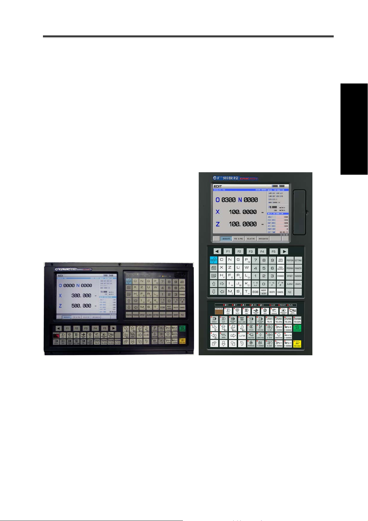
GSK980TDc is a new upgraded software, its software, hardware based on GSK980TDb, its
structure horizontal and vertical, matched with 8.4 inch color LCD, with 5 feed axes (including C axis),
2 analog spindles, least input increment 0.1μm. It uses the graphic interface, friendly human-machine
operation window. It can realize the PLC on-line display, real-time monitoring and MPG trial-cut
function.
Being upgraded product of GSK980TDb, GSK980TDc CNC turning is the better choice.
Ⅰ Programming
.
GSK980TDc GSK980TDc-V
X, Z, Y, 4
2ms interpolation period, control precision 1μm, 0.1μm
Max. speed 60m/min(up to 24m/min in 0.1μm)
Adapting to the servo spindle to realize the spindle continuously positioning, rigid tapping, and
the rigid thread machining
Built-in multi PLC programs, and the PLC program currently running can be selected
G71 supporting flute contour cycle cutting
Statement macro command programming, macro program call with parameter
Metric/inch programming, automatic toolsetting, automatic chamfer, tool life management
function
Chinese, English, Spanish, Russian display can be selected by parameters.
USB interface, U disc file operation, system configuration and software
th
, 5th ; axis name and axis type of Y, 4th, 5th can be defined
1

2-channel 0V~10V analog voltage output, two-spindle control
1-channel MPG input, MPG function
41 input signals and 36 output signals
Appearance installation dimension and command system are compatible with those of
GSK980TDb, GSK980TDa
Ⅰ Programming
1.1.2 Technical specification
Controllable axes
Controllable axes: 5(X, Z, Y , 4
Link axes:3
PLC controllable axes:3(X, Z, Y, 4
Feed axis function
Least input increment: 0.001mm(0.0001inch)and 0.0001mm(0.00001inch)
Least command increment:0.001mm(0.0001inch)and 0.0001mm(0.00001inch)
Position command range: ±99999999× least command unit
Rapid traverse speed:max. speed 60m/min in 0.001mm command unit, max. speed
24m/min in 0.0001mm command unit
Rapid override: F0, 25%, 50%, 100%
Feedrate override: 0~150% 16 grades to tune
Interpolation mode: linear interpolation, arc interpolation(three-point arc interpolation),
thread interpolation, ellipse interpolation, parabola interpolation and rigid tapping
Automatic chamfer function
GSK980TDc Turning CNC System User Manual
th,5th
)
th,5th
)
Thread function
General thread(following spindle)/rigid thread
Single/multi metric, inch straight thread, taper thread, end face thread, constant pitch
thread and variable pitch thread
Thread run-out length, angle, speed characteristics can be set
Thread pitch: 0.01mm~500mm or 0.06 tooth/inch~2540 tooth/inch
Acceleration/deceleration function
Cutting feed: linear
Rapid traverse: linear, S
Thread cutting: linear, exponential
Initial speed, termination speed, time of acceleration/deceleration can be set by
parameters
Spindle function
2-channel 0V~10V analog voltage output, two-spindle control
1-channel spindle encoder feedback, spindle encoder line can be set(100p/r~5000p/r)
Transmission ratio between encoder and spindle:(1~255):(1~255)
Spindle speed: it is set by S or PLC, and speed range: 0r/min~9999r/min
Spindle override: 50%~120% 8 grades tune
Spindle constant surface speed control
Rigid tapping
Tool function
2

Chapter 1 Programming
Tool length compensation
Tool nose radius compensation(C)
Tool wear compensation
Tool life management
Toolsetting mode: fixed-point toolsetting, trial-cut toolsetting, reference point return
toolsetting, automatic toolsetting
Tool offset execution mode: modifying coordinate mode, tool traverse mode
Precision compensation
Backlash compensation
Memory pitch error compensation
PLC function
Two-level PLC program,up to 5000 steps,the 1st program refresh period 8ms
PLC program communication download
PLC warning and PLC alarm
Many PLC programs(up to 16PCS), the PLC program currently running can be
selected
Basic I/O:41 input signals /36 output signals
Ⅰ Programming
Man-machine interface
8.4″ wide screen LCD,resolution: 640×480
Chinese, English, Spanish, Russian display
Planar tool path display
Real-time clock
Operation management
Operation mode: edit, auto, MDI, machine zero return, MPG/single, manual, program
zero return
Multi-level operation privilege management
Alarm record
Program edit
Program capacity: 40MB,384 programs(including subprograms and macro programs)
Edit function: program/block word search, modification, deletion
Program format: ISO command, statement macro command programming, relative
coordinate, absolute coordinate and compound coordinate programming
Program call: macro program call with parameter, 4-level program built-in
Communication function
RS232:two-way transmitting part programs and parameters, PLC program, system
software serial upgrade
USB:U file operation, U file directly machining, PLC program, system software U
upgrade
Safety function
Emergency stop
Hardware travel limit
Software travel check
Data backup and recovery
3
GSK980TDc Turning CNC System User Manual
d
d
A
G command table
Command Function Command Function Command Function
n
G00 Rapid traverse
(positioning)
Ⅰ Programming
G01
G02
G03
G04
G05
G6.2
G6.3
G7.2
G7.3
G12.1
G7.1
G15
G16
G17
G18
G19
G10
G11
G20
G21
G28
Linear interpolation
CW arc interpolation
CCW arc interpolation
Dwell, exact stop
Three-point arc
interpolation
Ellipse interpolation
(CW)
Ellipse interpolation
(CCW)
Parabola interpolation
(CW)
Parabola interpolation
(CCW)
Polar coordinate
interpolation
Cylinder interpolation
Polar coordinate
command cancel
Polar coordinate
command
Plane selection
command
Plane selection
command
Plane selection
command
Data input ON
Data input OFF
Input in inch
Input in metric
Reference point return
G30
G31
G32
G32.1
G33
G34 Thread cutting with variable
G36
G37
G40 Tool nose radius compensation
G41 Tool nose radius compensation
G42 Tool nose radius compensation
G50 Workpiece coordinate system
G52 Local workpiece coordinate
G54
G55
G56 Workpiece coordinate system 3
G57 Workpiece coordinate system 4
G58 Workpiece coordinate system 5
G59 Workpiece coordinate system 6
G65 Macro command non-modal
G66 Macro program modal call
G67 Macro program modal call
Automatic tool compensation X
Automatic tool compensation Z
r
2
, 3
, 4th reference point
return
Skip function
Constant pitch thread cutting
Rigid thread cutting
Z tapping cycle
lead
cancel
left
right
setting
system
Workpiece coordinate system 1
Workpiece coordinate system 2
call
cancel
G71
G72
G73
G70
G74
G75
G76
G80
G84
G88
G90
G92
G94
G96
G97
G98
G99
xial roughing cycle
(flute cycle)
Radial roughing cycle
Closed cutting cycle
Finishing cycle
Axial grooving cycle
Radial grooving cycle
Multiple thread cutting
cycle
Rigid tapping state
cancel
Axial rigid tapping
Radial rigid tapping
Axial cutting cycle
Thread cutting cycle
Radial cutting cycle
Constant surface speed
control
Constant surface speed
control cancel
Feed per minute
Feed per revolution
1.1.3 Environment and conditions
GSK980TDc storage delivery, working environment as follows:
Item Working conditions Storage delivery conditions
Ambient temperature
Ambient humidity ≤90%(no freezing) ≤95%(40 )℃
Atmosphere pressure
Altitude ≤1000m ≤1000m
4
0℃~45℃ -40℃~+70℃
86 kPa~106 kPa 86 kPa~106 kPa

1.1.4 Power supply
GSK980TDc can normally run in the following AC input power supply.
Voltage: within(0.85~1.1)×200V (rated AC input voltage);
Frequency: 49Hz~51Hz continuously changing
Chapter 1 Programming
1.1.5 Guard
GSK980TDc guard level is not less than IP20.
1.2 CNC System of Machine Tools and CNC Machine Tools
CNC machine tool is an electro-mechanical integrated product, composed of Numerical Control
Systems of Machine Tools, machines, electric control components, hydraulic components, pneumatic
components, lubricant, cooling and other subsystems (components), and CNC systems of machine
tools are control cores of CNC machine tools. CNC systems of machine tools are made up of
computerized numerical control(CNC), servo (stepper) motor drive devices, servo (or stepper) motor
etc.
Operational principles of CNC machine tools: according to requirements of machining
technology, edit user programs and input them to CNC, then CNC outputs motion control commands
to the servo (stepper) motor drive devices, and last the servo (or stepper) motor completes the cutting
feed of machine tool by mechanical driving device; logic control commands in user programs to
control spindle start/stop, tool selections, cooling ON/OFF, lubricant ON/OFF are output to electric
control systems of machine tools from CNC, and then the electric control systems control output
components including buttons, switches, indicators, relays, contactors and so on. Presently, the
electric control systems are employed with Programmable Logic Controller (PLC) with characteristics
of compact, convenience and high reliance. Thereof, the motion control systems and logic control
systems are the main of CNC machine tools.
GSK980TDc Turning Machine CNC system has simultaneously motion control and logic control
function to control two axes of CNC machine tool to move, and has nested PLC function. Edit PLC
programs (ladder diagram) according to requirements of input and output control of machine tool and
then download them to GSK980TDc Turning Machine CNC system, which realizes the required
electric control requirements of machine tool, is convenient to electric design of machine tool and
reduces cost of CNC machine tool.
Software used to control GSK980TDc Turning Machine CNC system is divided into system
software (NC for short) and PLC software (PLC for short). NC system is used to control the display,
communication, edit, decoding, interpolation and acceleration/deceleration, and PLC system for
controlling explanations, executions, inputs and outputs of ladder diagrams.
Standard PLC programs are loaded (except for the special order) when GSK980TDc Turning
Machine CNC System is delivered, concerned PLC control functions in following functions and
operations are described according to control logics of standard PLC programs, marking with
“Standard PLC functions” in GSK980TDc Turning CNC System User Manual. Refer to Operation
Manual of machine manufacturer about functions and operations of PLC control because the
machine manufacturer may modify or edit PLC programs again.
Ⅰ Programming
5

GSK980TDc Turning CNC System User Manual
Ⅰ Programming
Fig. 1-1
Programming is a course of workpiece contours, machining technologies, technology
parameters and tool parameters being edit into part programs according to special CNC
programming G codes. CNC machining is a course of CNC controlling a machine tool to complete
machining of workpiece according requirements of part programs.
Technical flow of CNC machining is as following Fig. 1-2.
Analyse workpiece drawings and confirm
machining processing
O0001;
G00 X3.76 Z0;
Edit part programs and record into CNC
Test part programs and execute trial run
G01 Z-1.28 F50;
…
M30;
%
Execute toolsetting and set tool offsets and
coordinates
Run part programs and machine workpiece
Check part dimension and modify part
programs and compensations
The machining ends and the workpiece is
formed
Fig. 1-2
6
Chapter 1 Programming
1.3 Programming Fundamentals
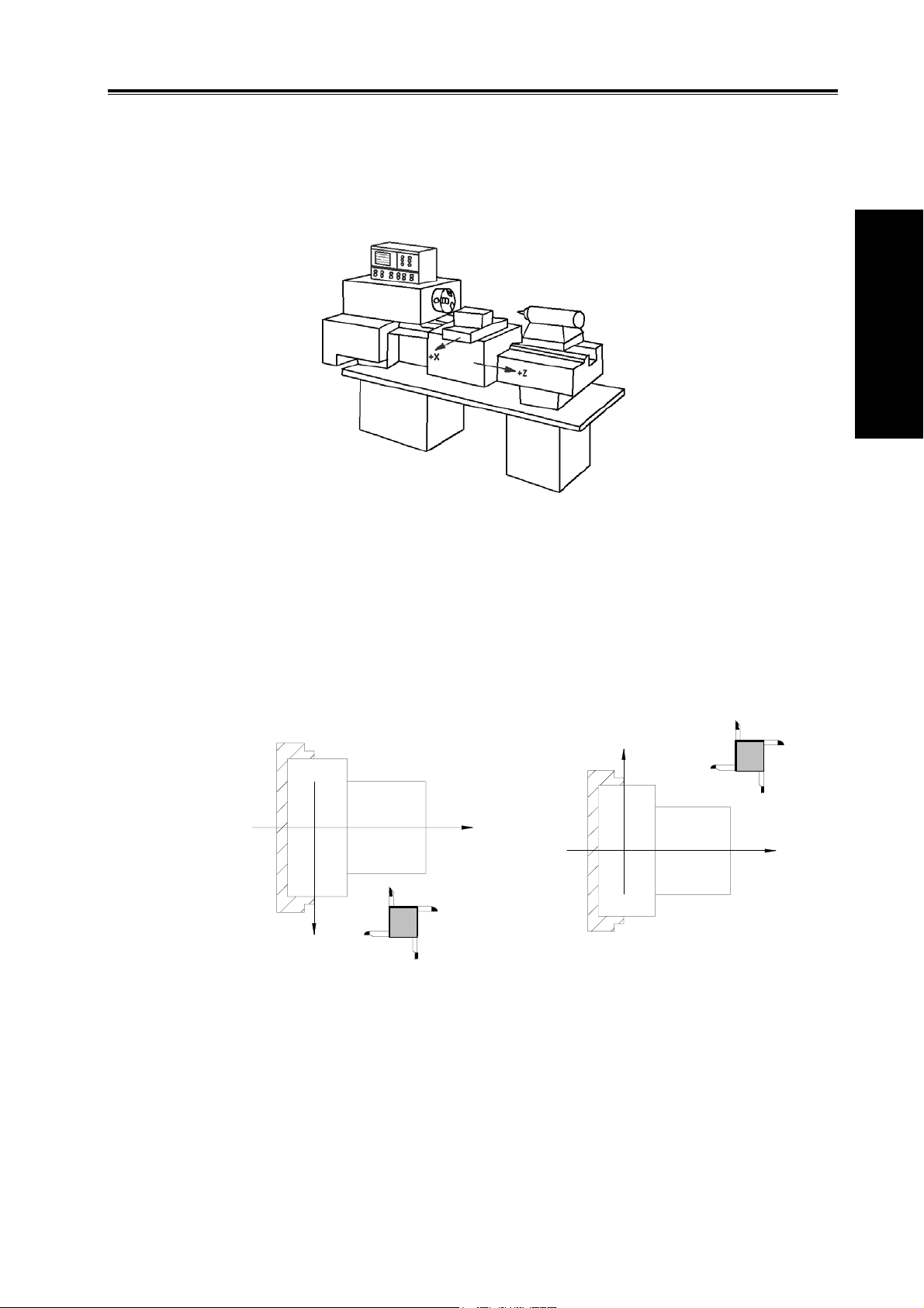
1.3.1 Coordinates definition
Sketch map of CNC turning machine is as follows:
Fig. 1-3
GSK980TDc uses a rectangular coordinate system composed of X, Z axis. X axis is
perpendicular with axes of spindle and Z axis is parallel with axes of spindle; negative directions of
them approach to the workpiece and positive ones are away from it.
There is a front tool post and a rear tool post of NC turning machine according to their relative
position between the tool post and the spindle, Fig. 1-4 is a coordinate system of the front tool post
and Fig. 1-5 is a rear tool post one. It shows exactly the opposite of X axes, but the same of Z axes
from figures. In the manual, it will introduce programming application with the front tool post
coordinate system in the following figures and examples.
Ⅰ Programming
X
Z
Z
X
Fig.1-4 Front tool post coordinate system Fig.1-5 Rear tool post coordinate system
1.3.2 Machine coordinate system, Machine Zero and machine reference point
Machine tool coordinate system is a benchmark one used for CNC counting coordinates and a
fixed one on the machine tool. Machine tool zero is a fixed point which position is specified by zero
switch or zero return switch on the machine tool. Usually, the zero return switch is installed on max.
stroke in X, Z positive direction. Machine reference point is located at the position at which the
machine zero value adding the data parameter No.114/No.115 value. When No.114/No.115 value is 0,
the machine reference point coincides with the machine zero. The coordinates of machine reference
7
GSK980TDc Turning CNC System User Manual
point is the No.120/No.121 value. Machine zero return/G28 zero return is to execute the machine
reference point return. After the machine zero return/machine reference point return is completed,
GSK980TDc machine coordinate system which takes No.120 value as the reference point, which is
referred to I Programming, Section 3.13.
Note: Do not execute the machine reference point return without the reference point switch installed on the
machine tool, otherwise, the motion exceeds the travel limit and the machine to be damaged.
Ⅰ Programming
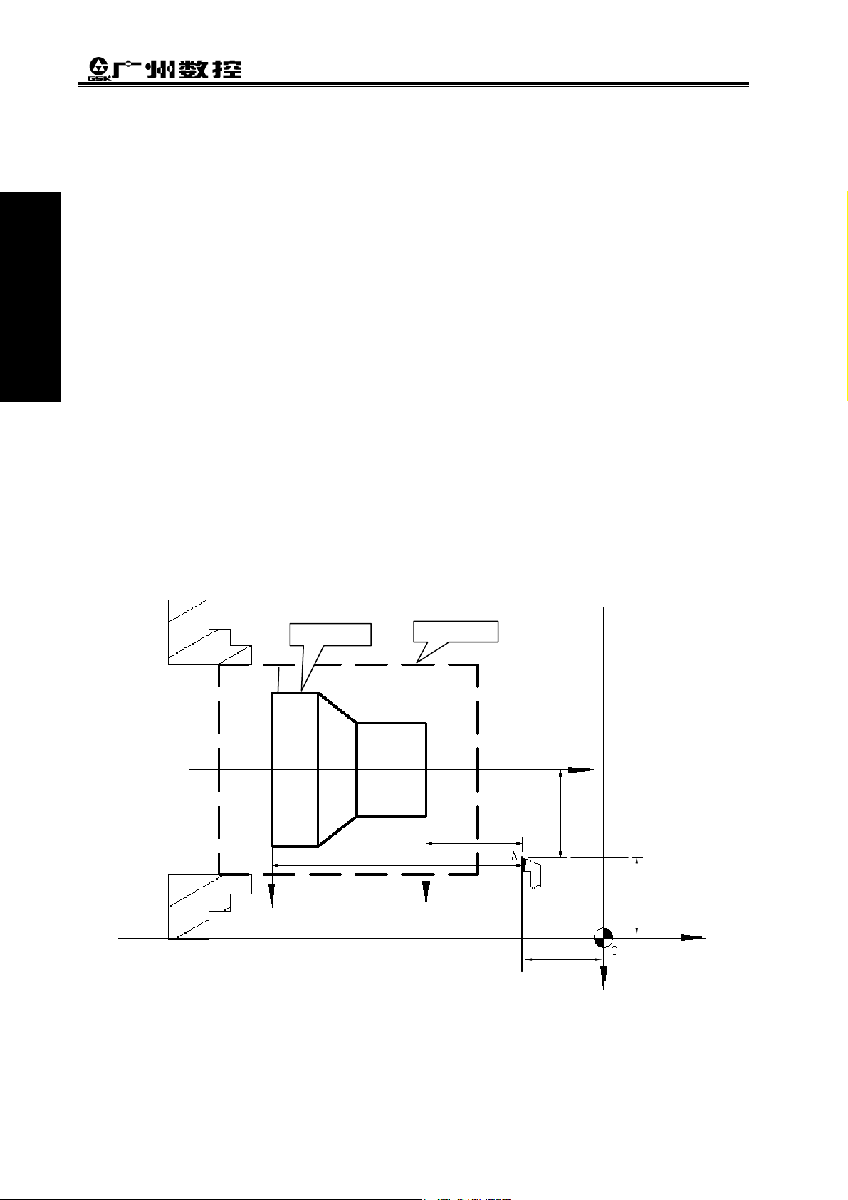
1.3.3 Workpiece coordinate system and Program Zero
The workpiece coordinate system is a rectangular coordinate system based on the part drawing,
also called floating coordinate system. After the workpiece is installed on the machine, the absolute
coordinates of tool’s current position is set by G50 according to the workpiece’s measure, and so the
workpiece coordinate system is established in CNC. Generally, Z axis of the workpiece coordinate
system coincides with the spindle axis. The established workpiece is valid till it is replaced by a new
one. The system can set 6 workpiece coordinate systems G54~G59 in advance. Refer to I
Programming, Section 3.18 about the details of workpiece coordinate system.
A sub workpiece coordinate system is created in a workpiece coordinate system, which is called
as a local coordinate system. Refer to I Programming, Section 3.17 about the details of the local
coordinate system.
The current position of workpiece coordinate system set by G50 is the program zero.
Note: Do not execute the machine reference point return without using G50 to set the workpiece coordinate
system after power on, otherwise, the alarm occurs.
Workpiece
O2
z
2
Rod
O
1
Z1 (Z2)
x
/2 (x2/2)
1
z
1
(x,z)
X2
X
1
(x
1,z1
2,z2
)
X/2
(x
)
Z
(0,0)
Z
Fig. 1-6
In the above figure, XOZ is the coordinate system of machine tool, X
coordinate system of X axis located at the heading of workpiece, X
is the one of X axis located
2O2Z2
at the ending of workpiece, O point is the machine reference point, A point is the tool nose and
X
is the workpiece
1O1Z1
8
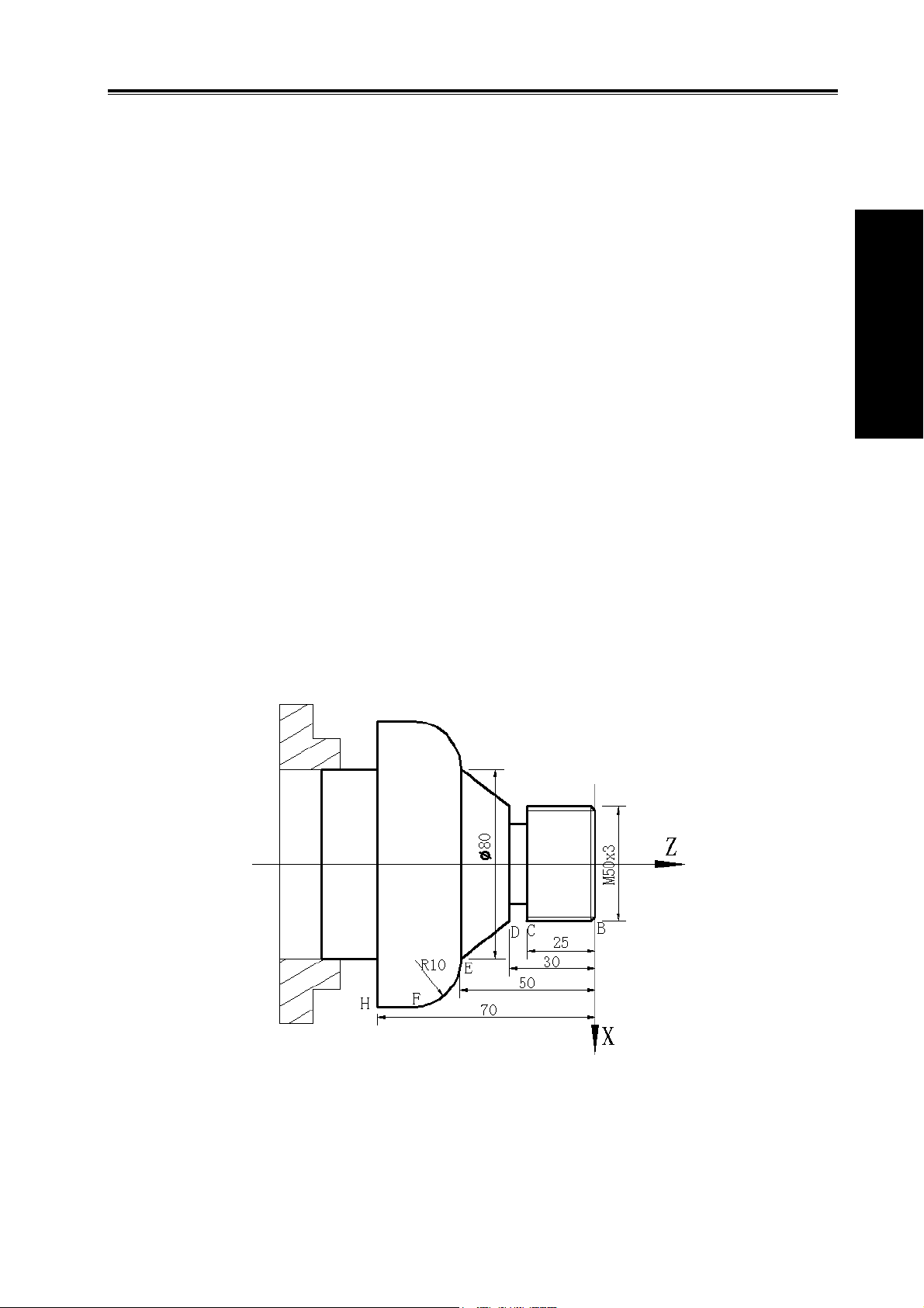
Chapter 1 Programming
coordinates of A point in the above-mentioned coordinate systems is as follows:
A point in the machine tool coordinate system: (x,z);
A point in X
A point in X
coordinate system: (x1,z1);
1O1Z1
coordinate system: (x2,z2).
2O2Z2
1.3.4 Interpolation function
Interpolation is defined as a planar or three dimensional contour formed by path of 2 or multiple
axes moving at the same time, also called Contour control. The controlled moving axis is called link
axis when the interpolation is executed. The moving distance, direction and speed of it are controlled
synchronously in the course of running to form the required Composite motion path. Positioning
control is defined that motion end point of one axis or multiple axes instead of the motion path in the
course of running is controlled.
GSK980TDc X and Z axis are link axes and 2 axes link CNC system. The system possesses
linear, circular and thread interpolation function.
Linear interpolation: Composite motion path of X, Z axis is a straight line from starting point to
end point.
Circular interpolation: Composite motion path of X, Z axis is arc radius defined by R or the circle
center (I, K) from starting point to end point.
Thread interpolation: Moving distance of X or Z axis or X and Z axis is defined by rotation angle
of spindle to form spiral cutting path on the workpiece surface to realize the
thread cutting. For thread interpolation, the feed axis rotates along with the
spindle, the long axis moves one pitch when the spindle rotates one rev,
and the short axis and the long axis directly interpolate.
Example:
Ⅰ Programming
Fig. 1-7
…
G32 W-27 F3; (B→C; thread interpolation)
G1 X50 Z-30 F100;
G1 X80 Z-50; (D→E; linear interpolation)
G3 X100 W-10 R10; (E→F; circular interpolation)
9
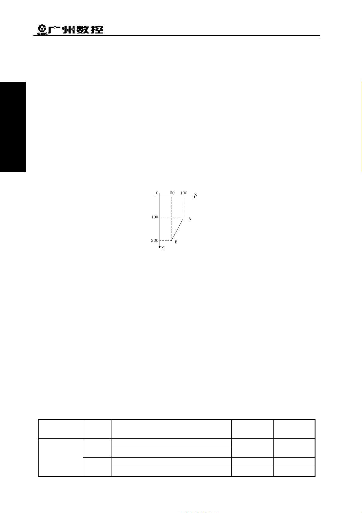
GSK980TDc Turning CNC System User Manual
…
M30;
1.3.5 Absolute programming and incremental programming
Ⅰ Programming
Specify coordinate values of path’s end point or target position in programming and there are 3
kinds of programming method according to coordinate values in programming: absolute programming,
incremental programming and compound programming.
Programming with X/Z axis absolute coordinate value to program (present with X, Z) is defined to
be the absolute programming;
Programming with X/Z axis incremental movement (present with U, W) is defined to be the
incremental programming;
In the system, X, Z axis separately uses the absolute programming and incremental program,
which is called the compound programming.
Example: A→B linear interpolation
Fig.1-8
Absolute programming: G01 X200 Z50;
Incremental programming: G01 U100 W-50;
Compound programming: G01 X200 W-50; or G01 U100 Z50
Note: When there are command address X/ U or Z/ W at the same time, X/Z command value is valid.
Example: G50 X10 Z20;
G01 X20 W30 U20 Z30; 【End point of the block (X20, Z30)】
1.3.6 Diameter programming and radius programming
Programming methods of X coordinate values are divided into: diameter programming and
radius programming.
Diameter programming: when NO.001 Bit2 is 0, X input command value is in diameter and X
coordinate is in diameter at the moment;
Radius programming: when NO.001 Bit2 is 1, X input command value is in radius and X
coordinate is in radius at the moment.
Addresses relevant to diameter or radius programming
Addresses
relevant to
diameter or
radius
10
Address Explanation
X
U
X coordinate
G50 setting X coordinate
X increment In diameter In radius
X finishing allowance in G71, G72, G73 In diameter In radius
Diameter
programming
In diameter In radius
Radius
programming
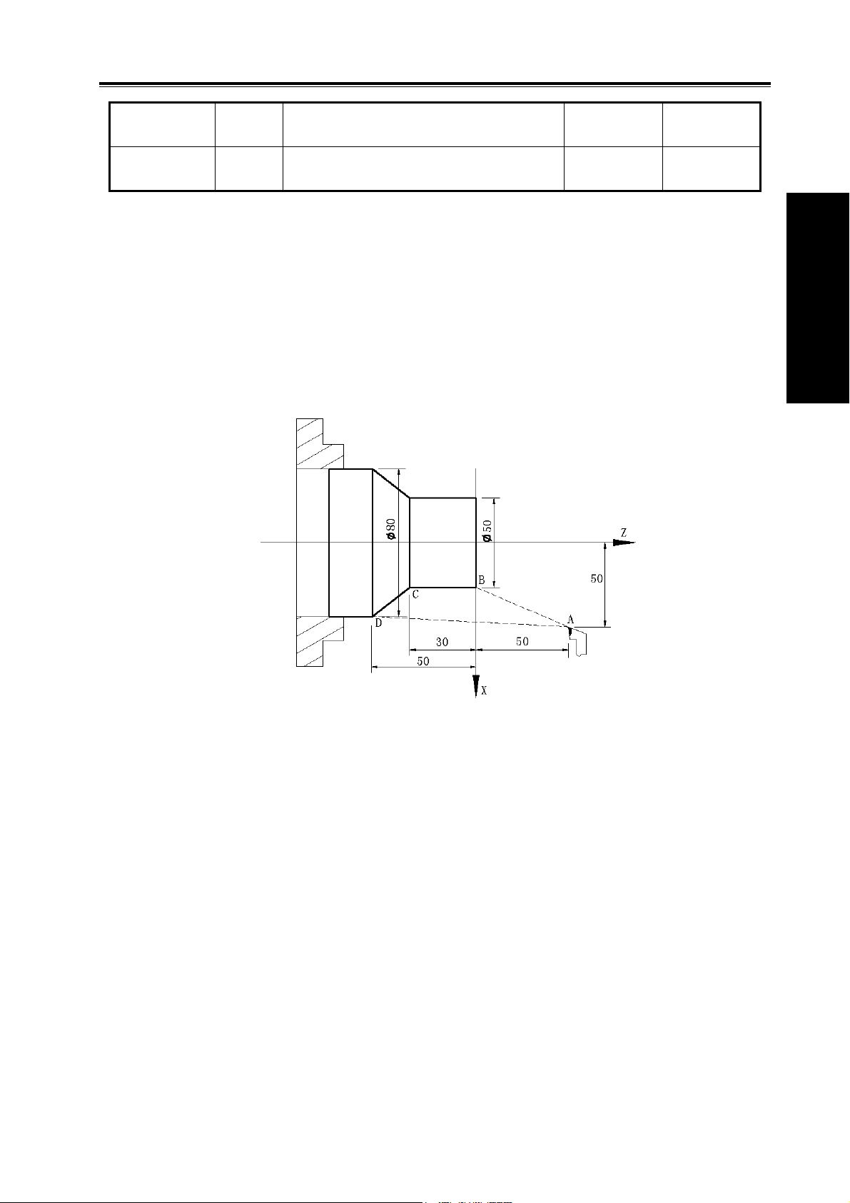
Chapter 1 Programming
programming Moving distance of tool retraction when
Except for addresses and data in Table 1-1, others (arc radius, taper in G90) are unrelated to
diameter or radius programming, and their input values in X direction are defined by the radius.
Note: The diameter programming is used except for the special description in the following explanation.
Address Explanation
cutting to the end point in G74
Diameter
programming
In diameter In radius
Radius
programming
1.4 Structure of an NC Program
User needs to compile part programs (called program) according to command formats of CNC
system. CNC system executes programs to control the machine tool movement, the spindle
starting/stopping, the cooling and the lubricant ON/OFF to complete the machine of workpiece.
Program example:
Ⅰ Programming
Fig. 1-9
The tool leaves the path of A→B→C→D→A after the above-mentioned programs are executed.
1.4.1 General structure of a program
A program consists of blocks. A block begins with a block number (it can be omitted) and several
words ending with “;”. General structure of a program is shown in Fig.1-10:
11
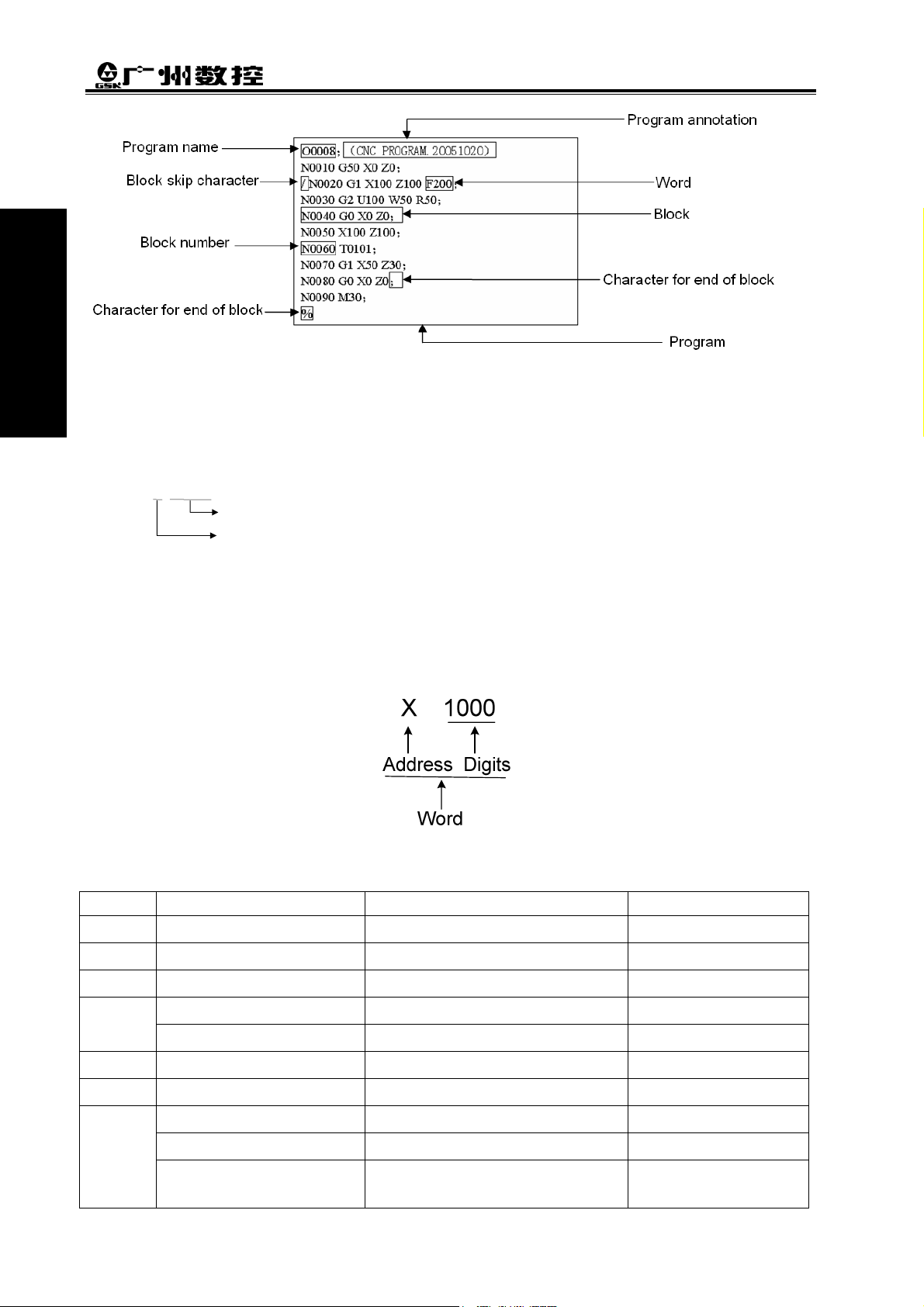
GSK980TDc Turning CNC System User Manual
Ⅰ Programming
Fig. 1-10 Structure of a program
Program name
There are most 384 programs stored in GSK980TDc. To identify it, each program has only one
program name (there is no the same program name) beginning with command address O and the
following 4 digits.
○ □□□□
Word
composed of an English letter (called command address) and the following number (operation
command with/without sign). The command address describes the meaning of its following operation
command and there may be different meaning in the same command address when the different
words are combined together. All words of GSK980TDc are in Table 1-2.
A word is the basic command unit to command CNC system to complete the control function,
Program number (0000~9999, the leading zero can be omitted)
Address O
Table 1-2 Word table
Address Command value range Function meaning Unit
12
O
N
G
X
Z
Y
U
-99999999~99999999 X coordinate Relevant to IS-B, IS-C
-99999999~99999999 Z coordinate Relevant to IS-B, IS-C
-99999999~99999999 Y coordinate Relevant to IS-B, IS-C
-99999999~99999999 X increment Relevant to IS-B, IS-C
0~9999 Program name
0~9999 Block number
00~99 Preparatory function
0~99999.999(s) Pause time
0~99999.999(s) Pause time
-99999~99999
X finishing allowance in G71,G72,
G73
Relevant to IS-B, IS-C
 Loading...