


 This user manual describes all items concerning the operation of this CNC system in detail. However, it is impossible to give particular descriptions for all unnecessary or unallowable operations due to length limitation and products application conditions Therefore, the items not presented herein should be considered impractical or unallowable.
 Copyright is reserved to GSK CNC Equipment Co., Ltd. It is illegal for any organization or individual to publish or reprint this manual. GSK CNC Equipment Co., Ltd. reserves the right to ascertain their legal liability.

DAT Series AC Servo Drive Unit User Manual
Preface
Your Excellency,
We are honored by your purchase of products from GSK CNC Equipment Co., Ltd. This manual introduces property, installation, connection, debugging, operation and maintenance of DAT Series AC Servo Driver in detail. To ensure safe and efficient work,
please read this manual carefully before installation and operation.
New products of DAT Series AC Servo Drive Unit include DAT2030, DAT2050,
DAT2075, DAT2100 and bus-type ones such as DAT2030C, DAT2050C, DAT2075C and DAT2100C.
This manual applies to the software version: V1.05 of DAT2000 series and V1.05 of DAT2000C series.
Please read the manual carefully before installation and using the product to ensure it works safely, normally and efficiently.
To avoid operator and other personal injury and machine damage, please pay special attention to the following warning label while you read the manual.
|
Danger |
If the motor operates incorrectly, it will cause damage or death. |
|
|
|
|
|
If the motor operates incorrectly, it will cause medium or slight |
|
|
|
|
|
|
|
Caution |
injury, even property loss. |
|
|
|
|
|
If this label is not noticed, unexpected result and situation will |
|
|
|
|
|
|
|
Note |
occur. |
|
|
|
|
|
|
Remind important requirements and instructions to user during the operation.
It indicates prohibition (mustn’t do)
It indicates forced execution (must do)
II

Cautions
Danger
III
DAT Series AC Servo Drive Unit User Manual
 Note
Note
The drive unit may startup when the power is recovered, the user don’t operate the shaft device of the servo motor.
If the user does not obey the instruction, it will cause personal injury.
Don’t put the cable on sharp edge. Don’t make the cable bear heavy load or tension.
If the user does not obey the instruction, it will cause electric shock, trouble or damage.
Don’t prevent heat diffusion or put object on radiator fan or radiator.
If the user does not obey the instruction, it will cause damage or a fire.
When removing the cover on the terminal board, the user don’t operate drive device
during power is on.
If the user does not obey the instruction, it will cause electric shock.
 Caution
IV

Cautions
 Caution
V

DAT Series AC Servo Drive Unit User Manual
Safety responsibility
Manufacturer Responsibility
——Be responsible for the danger which should be eliminated and/or controlled on design and configuration of the provided servo unit and accessories.
——Be responsible for the safety of the provided servo unit and accessories.
——Be responsible for the provided information and advice for the users.
User Responsibility
——Be trained with the safety operation of servo unit and familiar with the safety operation procedures.
——Be responsible for the dangers caused by adding, changing or altering to the original servo unit and the accessories.
——Be responsible for the failure to observe the provisions for operation, adjustment, maintenance, installation and storage in the manual.
This manual is kept by final user.
We are full of heartfelt gratitude to you for supporting us in the use of GSK’s products.
VI
|
|
|
Contents |
|
|
|
|
|
|
contents |
|
CHAPTER 1 PRODUCT INTRODUCTION ......................................................................................... |
1 |
||
1.1 |
Basic Knowledge ................................................................................................................. |
1 |
|
1.2 |
Confirmation of the Arrived Goods....................................................................................... |
6 |
|
|
1.2.1 Instruction of Servo Motor Model ............................................................................... |
6 |
|
|
1.2.2 Instruction of Servo Motor Models Unit...................................................................... |
7 |
|
|
1.2.3 Appearance of servo unit........................................................................................... |
8 |
|
1.3 |
Technical Specifications .................................................................................................. |
10 |
|
|
1.3.1 Servo motor technical specifications........................................................................ |
10 |
|
|
1.3.2 Technical Specification of Servo Unit ...................................................................... |
13 |
|
1.4 |
Order instruction .............................................................................................................. |
15 |
|
|
1.4.1 |
Order model example .............................................................................................. |
15 |
|
1.4.2 |
Standard Products Accessories............................................................................... |
17 |
CHAPTER 2 |
INSTALLATION ........................................................................................................ |
19 |
|
2.1 |
Servo Motor ....................................................................................................................... |
19 |
|
|
2.1.1 Mounting Dimension of the Servo Motor.................................................................. |
19 |
|
|
2.1.2 |
Servo Motor Installation ........................................................................................... |
21 |
2.2 |
Servo Unit .......................................................................................................................... |
22 |
|
|
2.2.1 |
Installation Dimension.............................................................................................. |
23 |
|
2.2.2 |
Mounting Interval ..................................................................................................... |
24 |
Chapter 3 CONNECTION................................................................................................................. |
25 |
||
3.1 |
Connection of Peripherals.................................................................................................. |
26 |
|
3.2 |
Terminal Connection of Main Circuit ................................................................................... |
30 |
|
|
3.2.1 Terminal Connection of Servo Unit .......................................................................... |
30 |
|
|
3.2.2 Instructions for Servo Motor Interface...................................................................... |
32 |
|
3.3 |
Connection of Control Signal ............................................................................................. |
33 |
|
|
3.3.1 Definition of Pin CN1 of DAT Series Products ......................................................... |
33 |
|
|
3.3.2 Input of Speed Command........................................................................................ |
35 |
|
|
3.3.3 Input of Position Command...................................................................................... |
36 |
|
|
3.3.4 |
Switching Value Input .............................................................................................. |
39 |
|
3.3.5 Output of Switch Value ............................................................................................ |
41 |
|
3.4 |
Connection of Feedback Signal ......................................................................................... |
44 |
|
|
3.4.1 Introductions for CN2 of DAT2000........................................................................... |
44 |
|
|
3.4.2 Introductions for CN2 OF DAT2000C ...................................................................... |
45 |
|
|
3.4.3 Connection to Encoder Signal of the Motor ............................................................. |
46 |
|
3.5 |
GSKLink Communication Function .................................................................................... |
48 |
|
3.6 |
Examples for Different Working Mode ............................................................................... |
50 |
|
|
3.6.1 Speed Mode Wiring of DAT2000 Series Products ................................................... |
50 |
|
|
3.6.2 Position Mode Connection of DAT2000 Series Products......................................... |
51 |
|
|
3.6.3 Speed Mode Connection of DAT2000C Series Products ........................................ |
52 |
|
|
3.6.4 Position Mode Connection of DAT2000C Series Products ...................................... |
53 |
|
CHAPTER 4 DISPLAY AND OPERATION....................................................................................... |
54 |
||
VII

DAT Series AC Servo Drive Unit User Manual
4.1 |
Operation Panel................................................................................................................. |
54 |
|
4.2 |
Display Menu..................................................................................................................... |
54 |
|
4.3 |
State Monitoring................................................................................................................. |
55 |
|
4.4 |
Parameter Setting.............................................................................................................. |
59 |
|
4.5 |
Parameter Management .................................................................................................... |
60 |
|
CHAPTER 5 DEBUGGING AND OPERATION ............................................................................. |
62 |
||
5.1 |
Manual and Jog operation ................................................................................................. |
63 |
|
|
5.1.1 |
Manual Operation .................................................................................................... |
64 |
|
5.1.2 |
Jog Operation .......................................................................................................... |
65 |
5.2 |
Speed mode operation ...................................................................................................... |
66 |
|
|
5.2.1 External analog voltage command .......................................................................... |
66 |
|
|
5.2.2 |
Internal digital command.......................................................................................... |
69 |
5.3 |
Position Mode Operation ................................................................................................... |
71 |
|
Chapter 6 FUNCTION DEBUGGING............................................................................................. |
73 |
||
6.1 |
Fundamental performance parameter debugging illustration............................................. |
73 |
|
6.2 |
Application of brake releasing signal ................................................................................. |
75 |
|
6.3 |
The switchover of motor rotating direction ......................................................................... |
79 |
|
6.4 |
Output of position feedback signal..................................................................................... |
80 |
|
6.5 |
Function Debugging of Position Mode ............................................................................... |
82 |
|
|
6.5.1 Position Command E-gear Ratio ............................................................................. |
82 |
|
|
6.5.2 |
Position arrival signal COIN ............................................................................. |
83 |
|
6.5.3 Pulse deviation zero clearing CLE ..................................................................... |
84 |
|
|
6.5.4 |
Pulse command inhibition INH ......................................................................... |
84 |
6.6 |
Function debugging under speed mode ............................................................................ |
84 |
|
|
6.6.1 Adjustment of analog command .............................................................................. |
84 |
|
|
6.6.2 |
Speed arrival signal COIN ................................................................................. |
85 |
|
6.6.3 |
Zero speed clamping ZSL ................................................................................. |
86 |
CHAPTER 7 |
PARAMETERS ......................................................................................................... |
87 |
|
7.1 |
Parameter List...................................................................................................................... |
87 |
|
7.2 |
Parameter Description.......................................................................................................... |
89 |
|
CHAPTER 8 ABNORMALITIES AND REMEDIES ........................................................................ |
98 |
||
8.1 |
Abnormalities Caused by Misuse ......................................................................................... |
98 |
|
8.2 |
Alarms and Remedies ........................................................................................................ |
100 |
|
8.3 |
Inspection and Maintenance .............................................................................................. |
105 |
|
APPENDIX A MODEL CODE PARAMETERS AND FEED SERVO MOTOR TABLE................. |
106 |
||
APPENDIX B |
PERIPHERAL EQUIPMENTS ............................................................................... |
108 |
|
B. 1 External Braking Resistor (Optional)................................................................................. |
108 |
||
B. 2 Circuit Breaker and Contactor (Necessary) ...................................................................... |
109 |
||
B.3 Three-Phase AC Filter (Recommended)............................................................................ |
110 |
||
B.4 Isolation Transformer (Necessary)..................................................................................... |
110 |
||
APPENDIX C VERSION UPGRADE INSTRUCTION ..................................................................... |
114 |
||
VIII
Chapter 1 Product Introduction
CHAPTER 1 PRODUCT INTRODUCTION
1.1Basic Knowledge
¾Basic principle of AC servo drive device
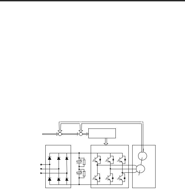
The AC servo drive unit consists of AC servo unit and AC servo motor (three-phase permanent magnet synchronous servo motor, hereafter referred to as the servo motor). Approximate sine wave current with 120° phase difference (namely: DC—AC) are generated in three-phase stator winding of the servo motor through controlling on/off of the power switch tube after three-phase alternating current is rectified to direct current by the servo unit (namely: AC—DC). Rotary magnetic field is formed by the sine wave current and the rotor of the servo motor is made of rare earth permanent materials that with fine anti-degaussing property, therefore, the interaction between the field of motor rotor and rotary field generates electromagnetic torque to rotate the rotor. The higher the current frequency flowing through the motor winding is, the faster speed will be. The bigger the current amplitude flowing through the motor winding is, the bigger the output torque (Torque=force × arm length of the force) will be.
The diagram of main return current, see Fig. 1-1, PG in the figure represents encoder.
Fig.1-1 Main return current diagram of the AC servo drive unit
¾Basic configuration of AC servo drive device
The servo unit receives the speed (or position) command from a control unit PC like
computerized numerical control system (CNC) to control the frequency and magnitude of the motor winding current, and make the speed (or rotor angle) of motor rotor approach to the speed (or position) command value. The deviation between the actual value of motor rotor speed (or rotor angle) and the command value is obtained through the feedback signal from the encoder. In addition, the servo unit constantly adjusts frequency and magnitude of the motor winding current to make the deviation between the actual value of motor speed (or rotor anger) and the command value within a required range. The basic configuration of the servo system is shown in Fig 1-2.
1

DAT Series AC Servo Drive Unit User Manual
setting
CNC |
|
Control |
Power drive unit |
Motor |
Driving |
|
|||||
equipment |
|
unit |
machine |
||
|
|
|
|||
|
|
|
|
|
|
Feedback check
Spindle servo drive equipment
Fig.1-2 Basic configuration of AC servo drive device
¾General concept of control
¾Control: The process of making the property (eg. Speed) of the object (eg. Servo motor) get or close to the predicted value is called control. The forementioned object is called controlled object. Controlled quantity (Variable): The property of the controlled object. Control unit (controller): The device to achieve control. Setting: The predicted value (command value) of the controlled quantity that is received by the control unit. Feedback: The controlled quantity is taken as input of the controller to affect itself. Feedback device: The device to detect the controlled quantity. According to the vary direction of controlled quantity and setting to the controller output, the feedback is divided into positive feedback (the same direction) and negative feedback (opposite direction). Control system consists of the controller used to achieve the controlled quantity control, the controlled object and the feedback device. The drive device is divided into closed-loop control and open-loop control according to the presence and absence of feedback device, and the position of feedback unit .The closed loop introduced in this manual are all closed loop of negative feedback.
In the AC servo drive unit introduced by this manual, servo unit is a controller, the servo motor is controlled object, the motor speed (or rotor angle) is a controlled quantity, the encoder of the servo motor is a feedback device. The actual speed is detected by the encoder and it is used to speed control to achieve speed feedback. Therefore, the AC servo drive unit belongs to closed loop control system.
z Open loop control: There is no feedback device in the control system, and the actual value of the controlled quantity does not affect the controller output. Example: Drive unit of step motor. After output current phase sequence of servo unit of step motor is changed, the rotation of rotor of the step motor should vary with it. Because the step motor are not usually installed speed or position feedback device, the rotation of motor rotor may not vary accurately with the changing of the current phase sequence, which causes so-called “step out”.
Open loop control is shown in Fig. 1-3.
Fig. 1-3 Open loop control
2
Chapter 1 Product Introduction
z Closed loop control: The controlled quantity of the control system is detected by feedback device and is output to the controller. This process affects the output of the controller and then changes the controlled quantity. According to the detection point of the feedback device, the closed loop control id divided into entirely closed loop control and semi closed loop control. Entirely closed loop control (Fig. 1-4): The controlled quantity is detected directly by the feedback device and it is used for feedback. Mechanical position is used as controlled quantity, grating ruler fixed on the machine as position feedback device, and the encoder of the servo motor is taken as a speed feedback device, realizing the entirely closed loop control of machine position. If the grating ruler is not fixed, the encoder of the servo motor is used as speed feedback device (Fig. 1-5), therefore, this is a semi-closed loop control of a mechanical position.
Fig. 1-4 Full-closed loop control
Fig. 1-5 semi-closed loop control
z PID Control: also called PID adjustment, is a common algorithm the controller adopted to mathematically deal with input data (setting, feedback). P stands for proportional, which means the input of the controller is to be linearly proportional to the output, the larger the adjustment coefficient is, the more sensitive the system will react and smaller the error is (can not completely eliminated), however, over larger adjustment coefficient will result in system oscillation and instability. I stands for integral, means time integral of system input affects the output (input gradually affects output), the larger the integration time constant is, the more stable the system will be, which can eliminate steady-state error but slows system response at the same time. D stands for differential, which means input differential (slope of input change) affects output, differential control may predict deviation and produce advanced correction action to decrease tracking error and improve dynamic performance; while over large differential coefficient will also result in system oscillation and instability. Along with the adjustment of PID control coefficient at specific control system, the proportional, integral and differential adjustment are mutually affected to make a balance between system reaction speed, control accuracy and stability. As differential adjustment is prone to produce impact and oscillation, the servo system introduced in this manual adopts PI adjustment, that is, proportional and differential adjustment.
3
DAT Series AC Servo Drive Unit User Manual
¾Concepts of servo control
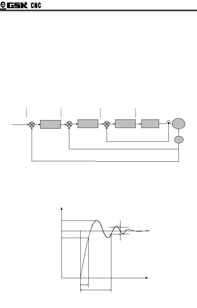
There are three basic control models in servo system: location control, speed control and
torque control. The system chart is shown in Fig. 1-6.
zPosition control: set the direction and angle of motor rotation through digital pulse or data communication, the motor rotor controlled by servo unit will rotate to the corresponding angle in accordance with the preset direction. The rotary angle (position) and speed are both controllable.
zSpeed control: set the direction and angle of motor rotation through analog voltage or data communication, the motor rotor controlled by servo unit will rotate in accordance with the set direction and speed.
zTorque control: set the value and direction of the motor output torque through analog voltage or data communication, the servo unit controls the motor rotor’s rotation direction and the value of output torque.
The servo device introduced in this manual does not receive signals set by torque at present and the torque control operational mode is not available for the time being.
|
Position |
|
Speed |
|
Current |
|
|
|
|
controller |
|
controller |
|
controller |
|
|
|
|
|
Position |
|
Speed |
|
Current |
Power |
Motor |
|
|
adjustment |
|
adjustment |
|
adjustment |
amplification |
|
Command |
|
|
|
|
||||
|
Position |
|
|
|
|
|
|
|
position |
|
|
Speed feedback |
|
Current feedback |
|
|
|
|
feedback signal |
|
signal |
|
signal |
|
PG |
|
|
|
|
|
|
|
|||
Fig. 1-6 Three-loop control diagram
¾Servo performance index
Servo dynamic reaction characteristics: refers to the reaction speed, dynamic control error and stable control error of the servo system with set signal or load change. Fig. 1-7 indicates reaction characteristics of the servo system set with step signals (solid line represents the setting signal and dashed line represents the output signal of the servo system).
Fig. 1-7 Servo dynamic reaction curve
4
Chapter 1 Product Introduction
Rise time tr: the length of time of the speed quantity rise for the first time from zero to 90% of a stable value R (t), which shows the rapidity of dynamic reaction.
Adjustment time ts The minimum time needed to make the reaction curve reach but not exceed error interval which is used to measure the whole adjustment tempo of the device. The allowed interval refers to plus or minus 5% of the stable value proximal to the step reaction curve stable value R (t).
Overshoot σ The ratio between the maximum D-value that the rotation output quantity overpasses the stable value Rmax(t)- R (t) and the stable value R (t), which reflects the relative stability of the servo device and expressed as percentages, i.e.:
σ(%) = Rmax (t) − R(t) ×100%
R(t)
Steady-state error: the difference between the expected output steady-state value and the practical output value after the system rotation speed turned into stable.
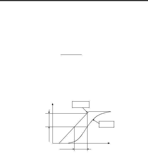
Servo static performance: Stability is the most important issue of the servo control system. Servo static performance index, mainly the position accuracy, refers to deviation degree between the practical state and expected state when the system transient process comes to cease. Not only errors from the position measurement device and from the system will affect servo steady-state accuracy, but the internal structure and parameters of the system can also matter. Fig.1-8 shows the position servo static curve.
Fig. 1-8 Position servo static curves
Tracking error: The difference between the movable position of the workbench requested by the command signals (commanding position) and the practical movable position, i.e., tracking error equals to the value of commanding position minus the value of practical position.
Servo rigidity: servo system’s capability to resist the position deviation resulted from load interference.
5
DAT Series AC Servo Drive Unit User Manual
1.2Confirmation of the Arrived Goods
Please promptly inspect the received goods in accordance with the following items, any question, please feel free to contact suppliers or our company.
Inspected Items |
Notes |
|
|
|
|
Check and confirm if the servo units |
Please check by the nameplates on the servo units |
|
and servo motors are the ordered. |
and servo motors |
|
|
|
|
Accessories complete or not |
Please check accessories according to packing list, |
|
any unmatched ones, refer to order instruction 1.4. |
||
|
||
|
|
|
Damaged or not in transport |
Check the general appearance of goods to ensure |
|
products intact and with no damage. |
||
|
||
|
|
|
Screw loose or not |
Please check if there is any screw loose with |
|
screwdrivers. |
||
|
||
|
|
1. Damaged AC servo unit or the ones without integrated parts can not be installed.
2.AC servo unit should be matched with servo motor with proper property.
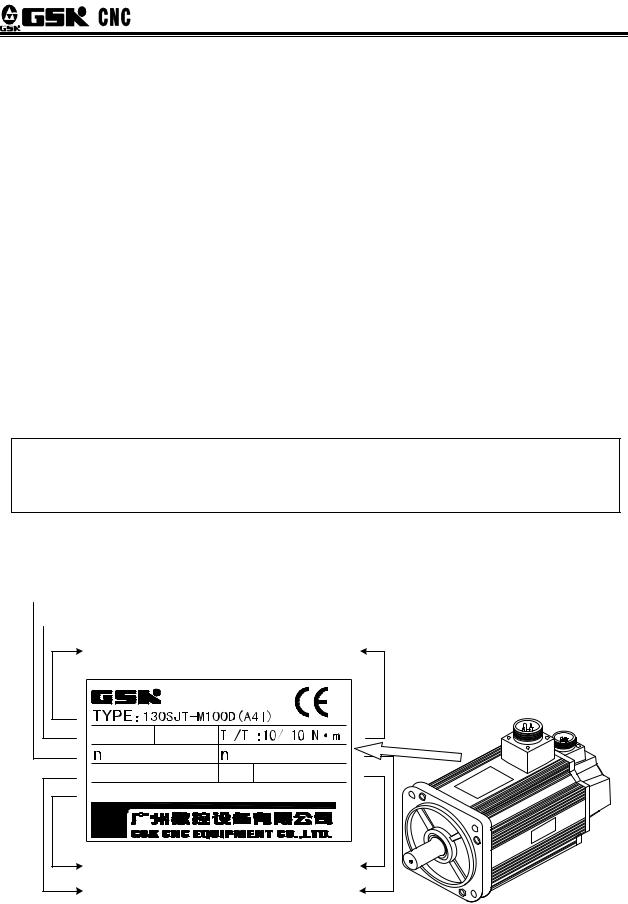
1.2.1Instruction of Servo Motor Model
 Rated speed
 Rated voltage and rated current
Servo motor model |
Rated torque |
UN:220V IN :10A |
S |
N |
|
N: |
2500r/min |
max: 3000 r/min |
|
INS.CLASS: B |
IP65 M: 17 bit |
||
S/N: 081016100D0000107H |
|||
Product No. |
Grade of protection |
|
Encoder lines |
||
|
||
Class of Insulation |
Max speed |
Fig. 1-9 Instruction of servo motor models:
6
|
|
|
|
|
|
|
|
|
|
|
|
|
|
|
|
|
|
|
|
|
|
|
|
|
|
|
|
|
Chapter 1 |
Product Introduction |
||||||||||
|
|
|
|
|
|
|
|
|
|
|
|
|
|
|
|
|
|
|
|
|
|
|
|
|
|
|
|
|
|
|
|
|
|
|
|
|
|
|
|
|
|
|
130 |
|
SJT M Z 150 D A□ Y□ X□ |
||||||||||||||||||||||||||||||||||||
|
|
|
|
|
|
|
|
|
|
|
|
|
|
|
|
|
|
|
|
|
|
|
|
|
|
|
|
|
|
|
|
|
|
|
|
|
|
|||
|
Machine model |
|
|
|
|
|
|
|
|
|
|
|
|
|
|
|
|
|
|
|
|
|
|
|
|
|
|
|
|
|
|
|
|
|
Non:Aviation sockettype |
|||||
|
|
|
|
|
|
|
|
|
|
|
|
|
|
|
|
|
|
|
|
|
|
|
|
|
|
|
|
|
|
|
|
|
|
|
|
|||||
|
|
|
|
|
|
|
|
|
|
|
|
|
|
|
|
|
|
|
|
|
|
|
|
|
|
|
|
|
|
|
|
|
|
|
|
|
|
|
X:Cable direct type |
|
|
AC synchonic servo motor |
|
|
|
|
|
|
|
|
|
|
|
|
|
|
|
|
|
|
|
|
|
|
|
|
|
|
|
|
|
|
|||||||||
|
|
|
|
|
|
|
|
|
|
|
|
|
|
|
|
|
|
|
|
|
|
|
|
|
|
|
|
|||||||||||||
|
|
|
|
|
|
|
|
|
|
|
|
|
|
|
|
|
|
|
|
|
|
|
|
|
|
|
|
|
|
|
|
|
|
|
|
Shaft or installation config.#3 |
|
|||
|
M:Photoelectric encoder |
|
|
|
|
|
|
|
|
|
|
|
|
|
|
|
|
|
|
|
|
|
|
|||||||||||||||||
|
|
|
|
|
|
|
|
|
|
|
|
|
|
|
|
|
|
|
|
|
|
Non:Standard shaft |
||||||||||||||||||
|
|
|
|
|
|
|
|
|
|
|
|
|
|
|
|
|
|
|
|
|
|
|||||||||||||||||||
|
|
|
|
|
|
|
|
|
|
|
|
|
|
|
|
|
|
|
|
|
|
|
|
|
|
|
|
|
|
|
|
|
|
|
||||||
|
|
|
|
|
|
|
|
|
|
|
|
|
|
|
|
|
|
|
|
|
|
|
|
|
|
|
|
|
|
|
|
|
|
|
Y□:Special ballpoint shaft |
|||||
|
Non:Non-electricity-breaking brake |
|
|
|
|
|
|
|
|
|
|
|
|
|
|
|
|
|
|
|
|
|||||||||||||||||||
|
|
|
|
|
|
|
|
|
|
|
|
|
|
|
|
|
|
|
|
|
Z□:Special cone shaft |
|||||||||||||||||||
|
Z:With-electricity-breaking brake |
|
|
|
|
|
|
|
|
|
|
|
|
|
|
|
|
|
|
|
|
|||||||||||||||||||
|
|
|
|
|
|
|
|
|
|
|
|
|
|
|
|
|
|
|
|
|
S□:Stepping motor installation config. |
|||||||||||||||||||
|
|
|
|
|
|
|
|
|
|
|
|
|
|
|
|
|
|
|
|
|
|
|
|
|
|
|
|
|
|
|
|
|
|
|
||||||
|
Zero-speed torque |
2 |
|
|
|
|
|
|
|
|
|
|
|
|
|
|
|
|
|
|
|
|
|
|
|
|
|
|
|
|
|
Encoder type |
||||||||
|
150: 15N·m |
|
|
|
|
|
|
|
|
|
|
|
|
|
|
|
|
|
|
|
|
|
|
|
A or None: |
Increment type 2500 p/r |
||||||||||||||
|
|
|
|
|
|
|
|
|
|
|
|
|
|
|
|
|
|
|
|
|
|
|
|
|
|
|
|
|
|
|
A2 Increment type 5000 p/r |
|||||||||
|
|
|
|
|
|
|
|
|
|
|
|
|
|
|
|
|
|
|
|
|
|
|
|
|
|
|
|
|
|
|
||||||||||
|
|
|
|
|
|
|
|
|
|
|
|
|
|
|
|
|
|
|
|
|
|
|
|
|
|
|
|
|
|
|
||||||||||
|
Rated |
|
A 1000 r / min |
|
|
|
|
|
|
|
|
|
|
|
|
|
|
|
|
|
|
A3:Increment split-type 5000 p/r |
||||||||||||||||||
|
|
|
|
|
|
|
|
|
|
|
|
|
|
|
|
|
|
|
|
|||||||||||||||||||||
|
|
|
|
|
|
|
|
|
|
|
|
|
|
|
|
|
|
|
A4:Absolute type 17bit |
|||||||||||||||||||||
|
|
B 1500 r / min |
|
|
|
|
|
|
|
|
|
|
|
|
|
|
|
|
|
|
||||||||||||||||||||
|
rotation |
|
|
|
|
|
|
|
|
|
|
|
|
|
|
|
|
|
|
A41:Danaher multi-circle 17bit absolute type |
||||||||||||||||||||
|
|
C 2000 r / min |
|
|
|
|
|
|
|
|
|
|
|
|
|
|
|
|
|
|
||||||||||||||||||||
|
|
|
|
|
|
|
|
|
|
|
|
|
|
|
|
|
|
|
||||||||||||||||||||||
|
speed |
|
D 2500 r / min |
|
|
|
|
|
|
|
|
|
|
|
|
|
|
|
|
|
A4S1:Danaher single-17bit absolute type |
|||||||||||||||||||
|
|
|
|
|
|
|
|
|
|
|
|
|
|
|
|
|
|
|
|
|
|
|
|
|
|
|||||||||||||||
|
|
|
E 3000 r / min |
|
|
|
|
|
|
|
|
|
|
|
|
|
|
|
|
|
|
|
|
|
|
|
|
|
|
|
||||||||||
|
|
|
|
|
|
|
|
|
|
|
|
|
|
|
|
|
|
|
|
|
|
|
|
|
|
|
|
|||||||||||||
|
|
|
|
|
|
|
|
|
|
|
|
|
|
|
|
|
|
|
|
|
|
|
|
|
|
|
|
|
|
|
|
|
|
|
|
|
|
|
|
|
#1 Working power of electricity-breaking brake: DC 0.9 1.1 ×24V, interface: triax socket, 1,2 pin are power terminals (have no polarity), 3 pin is the earth terminal. When the 1 and 2 pin plug in power, the electricity-breaking brake doesn’t work, while when the power is disconnected, it will brake and the operating time is less or equal to 0.1s.
#2 A three-digital number “150” is used to show its value: 150×10-1=15, unit: N.m.
#3 ‘□’ is a numeric codes, please refer to the installation outline drawing of the motor for the special shaft represented by a certain number.
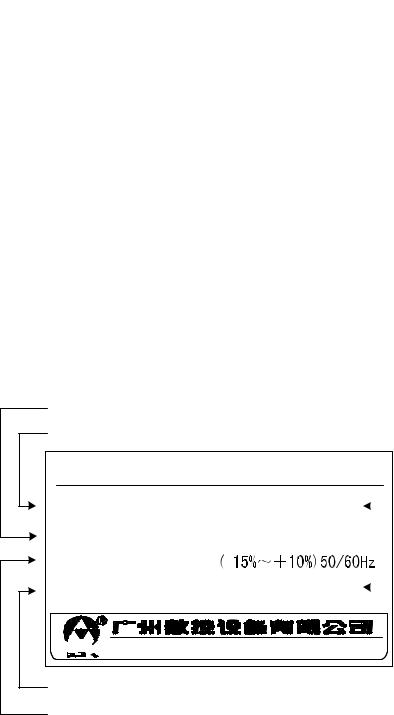
1.2.2Instruction of Servo Motor Models Unit
Nameplate examples:
Motor model corresponded to factory parameter of the drive unit
Drive unit order model
Digital AC servo drive unit
Model : DAT2075C |
Version: V1.05 |
|
Software version |
||
|
|||||
Adapted motor:130SJT-M150D A4 |
|
of Drive unit |
|||
|
|
||||
Power:3-phase 220V |
|
|
|
|
Production date |
|
Date:2009/3 |
|
|||
SN:E03DN00088 |
|
|
|||
|
|
of drive unit |
|||
|
|
|
|
|
|


 Tel.020-81986247 Fax.81993683
Production No. of drive unit
Power of drive unit
7
DAT Series AC Servo Drive Unit User Manual
DAT 2 050 C 130 SJT M 150 D A □Y □X □
 Matching AC servo motor model (omit if no matching)
Communications Mode:
C: GSKLink serial communications
None: No serial communications function
|
|
|
|
IPM module nominal current |
|
|
|
|
||
|
|
|
|
|
|
030 30A |
||||
|
|
|
|
|
|
|||||
|
|
|
|
|||||||
|
|
|
|
|
|
|
|
|
|
050 50A |
|
|
|
|
|
|
|
|
|
|
|
|
|
|
|
|
Input power grade:2 AC220V |
|
|
075 75A |
||
|
|
|
|
|
||||||
|
|
|
|
|
|
|
|
|
|
100 100A |
|
|
|
|
|
|
|
|
|
|
|
|
|
|
Product model code |
|
|
|
|
|||
|
|
|||||||||
|
|
|
|
|
|
|
|
|||
|
|
|
|
|
|
|
|
|
|
|
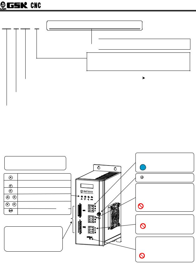
1.2.3Appearance of servo unit
zAppearance of DAT2030 and DAT2050
8

Chapter 1 Product Introduction
zAppearance of DAT2030C and DAT2050C
LED Monitoring window:
composed of 6 LED nixie tubes and able to carry out monitoring under all operating models
and make parameters revision and management.
Parameter sequence, parameter value increase
Parameter sequence, parameter value decrease
Back to the previous menu, or cancel operation
The parameter value increase 100 for 
 every pushing of the combination button
|
The parameter value decrease 100 for |
every pushing of the combination button |
Step to the next menu, or cancel operation
CN1: Control signal interface:
Insert external speed command, position command and input, output signals
CN2: Encoder feedback input interface Increment-type encoder differential signal, motor position feedback input
CN4, CN5, GSKLlink Commnuincations Interface Connect with GSKLlink serial bus through which the CNC system can achieve servo module and real-time monitoring.
zAppearance of DAT2075 and DAT2100
R S T Drive unit power input terminal Voltage range: 3-Phase AC 220V
Please lead power through protector
!device such as circuit breaker.
Input power ground, motor protector ground earth terminal
P B1 B Dynamic braking resistor inserting end: when attach external braking resistor, switch the resistor on P. B end, no B1 end; attach internal braking resistor, short-circuit
B1 B end, no P end. Refer to Appendix B1 for braking resistor selection.
Short-circuit of P B ends are not allowed.
U V WInserting end of motor power
Serial connecting capacitive device between drive unit and motor for filtering processing is not allowed.
Indicator light:” CHANGE” high voltage indicator light ON: DC bus with high voltage OFF: DC bus discharged off
When Indicator light ON, No dismantle or install drive unit, power lines, motor line and braking resistor lines.
9
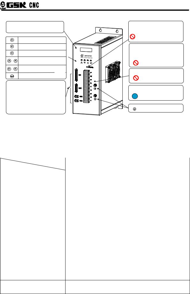
DAT Series AC Servo Drive Unit User Manual
zAppearance of DAT2075C,DAT2100C
1.3Technical Specifications
1.3.1Servo motor technical specifications
Table 1-1 Principle Technical Parameters of 80SJT Series Motor
Model |
80SJT-M024C |
80SJT-M024E |
80SJT-M032C |
80SJT-M032E |
|
Project |
(A□) |
(A□) |
(A□) |
(A□) |
|
|
|
|
|
|
|
Rated Voltage kW |
0.5 |
0.75 |
0.66 |
1.0 |
|
|
|
|
|
|
|
Pole-pairs |
|
|
4 |
|
|
|
|
|
|
|
|
Rated Current A |
3 |
4.8 |
5 |
6.2 |
|
|
|
|
|
|
|
Zero-speed Torque N·m |
2.4 |
2.4 |
3.2 |
3.2 |
|
|
|
|
|
|
|
Rated Torque N·m |
2.4 |
2.4 |
3.2 |
3.2 |
|
|
|
|
|
|
|
Maximum Torque N·m |
7.2 |
7.2 |
9.6 |
9.6 |
|
|
|
|
|
|
|
Rate Rotary speed r/min |
2000 |
3000 |
2000 |
3000 |
|
|
|
|
|
|
|
Maximum Rotary speed r/min |
2500 |
4000 |
2500 |
4000 |
|
|
|
|
|
|
|
Moment of Inertia kg·m2 |
0.83×10⁻⁴ |
0.83×10⁻⁴ |
1.23×10⁻⁴ |
1.23×10⁻⁴ |
|
Weight kg |
2.8 |
2.9 |
3.4 |
3.5 |
|
|
|
|
|
|
|
Insulation Grade |
|
F GB |
755—2008 |
|
|
|
|
|
|
|
|
Oscillation Grade |
|
R GB 10068—2008 |
|
|
|
|
|
||||
Protection Grade |
IP65 GB 4208—2008/IEC 60529 2001 GB/T 4942.1—2006 |
|
|||
|
|
|
|||
Installation Type |
IMB5 Flange installation GB/T 997—2008 / IEC 60034-7:2001 |
||||
|
|
||||
character of service |
S1 Continuous duty GB 755—2008 |
|
|||
|
|
|
|
|
|
electricity-breaking brake |
|
Not available |
|
|
|
Adaptive Encoder
Increment-type 2500 p/r,5000 p/r etc absolute encoder17bit single-circuit or multi-coil
10

Chapter 1 Product Introduction
Table 1-2 Principle Parameters of 110SJT Series, 130SJT Series Motor
Model |
110SJT-M |
110SJT-M |
110SJT-M |
110SJT-M |
130SJT-M |
130SJT-M |
|||
Project |
040D(A□) |
040E(A□) |
|
060D(A□) |
060E(A□) |
|
040D(A□) |
050D(A□) |
|
|
|
|
|||||||
|
|
|
|
|
|
|
|
|
|
Rated Voltage kW |
1.0 |
1.2 |
|
1.5 |
|
1.8 |
|
1.0 |
1.3 |
Pole-Pairs |
|
|
|
|
4 |
|
|
|
|
|
|
|
|
|
|
|
|
||
Rated Current A |
4.5 |
5 |
|
7 |
|
8 |
|
4 |
5 |
Zero-speed Torque |
4 |
4 |
|
6 |
|
6 |
|
4 |
5 |
N·m |
|
|
|
|
|||||
|
|
|
|
|
|
|
|
|
|
|
|
|
|
|
|
|
|
|
|
Rated Torque N·m |
4 |
4 |
|
6 |
|
6 |
|
4 |
5 |
|
|
|
|
|
|
|
|
|
|
Maximum Torque (N·m |
12 |
10 |
|
12 |
|
12 |
|
10 |
12.5 |
|
|
|
|
||||||
|
|
|
|
|
|
|
|
|
|
Rated Rotary speed |
2500 |
3000 |
|
2500 |
|
3000 |
|
2500 |
2500 |
r/min |
|
|
|
||||||
|
|
|
|
|
|
|
|
|
|
|
|
|
|
|
|
|
|
|
|
Maximum Rotary speed |
3000 |
3300 |
|
3000 |
|
3300 |
|
3000 |
3000 |
r/min |
|
|
|
||||||
|
|
|
|
|
|
|
|
|
|
Moment of Inertia |
0.68×10⁻³ |
0.68×10⁻³ |
|
0.95×10⁻³ |
|
0.95×10⁻³ |
|
1.1×10⁻³ |
1.1×10⁻³ |
kg·m2 |
|
|
|
|
|
|
|
|
|
Weight kg |
6.1 |
6.1 |
|
7.9 |
|
7.9 |
|
6.5 |
6.5 |
|
|
|
|
|
|
|
|
|
|
Weight of motor with |
|
|
|
|
|
|
|
|
|
electricity-breaking |
7.7 |
7.7 |
|
9.5 |
|
9.5 |
|
8.1 |
8.1 |
brake kg |
|
|
|
|
|
|
|
|
|
|
|
|
|
|
|
|
|
|
|
Insulation Grade |
|
|
|
B GB 755-2008 |
|
|
|||
|
|
|
|
|
|
|
|||
Oscillation Grade |
|
|
|
R GB 10068-2008 |
|
|
|||
|
|
|
|
|
|
||||
Protection Grade |
|
|
IP65 GB/T4942.1-2006 |
|
|
||||
|
|
||||||||
Installation Type |
IMB5 Flange Installation GB/T 997-2008 / IEC 60034-7:2001 |
||||||||
|
|
|
|
||||||
Character of Service |
|
S1 Continuous Duty GB 755-2008 |
|
||||||
Adaptive Encoder
Increment-type 2500 p/r,5000 p/r etc absolute encoder17bit single-circuit or multi-coil
Table 1-2 Principle Parameters of 110SJT Series, 130SJT Series Motor continue
Model |
130SJT-M |
130SJT-M |
130SJT-M |
130SJT-M |
130SJT-M |
130SJT-M |
|
Project |
060D(A□) |
075D(A□) |
100B(A□) |
100D(A□) |
150B(A□) |
150D(A□) |
|
|
|
|
|
|
|
|
|
Rated Voltage kW |
1.5 |
1.88 |
1.5 |
2.5 |
2.3 |
3.9 |
|
|
|
|
|
|
|
|
|
Pole-Pairs |
|
|
|
4 |
|
|
|
|
|
|
|
|
|
|
|
Rated Current A |
6 |
7.5 |
6 |
10 |
8.5 |
14.5 |
|
|
|
|
|
|
|
|
|
Zero-speed Torque |
6 |
7.5 |
10 |
10 |
15 |
15 |
|
N·m |
|||||||
|
|
|
|
|
|
||
Rated Torque N·m |
6 |
7.5 |
10 |
10 |
15 |
15 |
|
|
|
|
|
|
|
|
|
Maximum Torque (N·m |
18 |
20 |
25 |
25 |
30 |
30 |
|
|
|
|
|
|
|
|
11

DAT Series AC Servo Drive Unit User Manual
Rated Rotary speed |
|
|
2500 |
|
2500 |
1500 |
|
2500 |
|
|
1500 |
|
2500 |
|
|||
r/min |
|
|
|
|
|
|
|
|
|||||||||
|
|
|
|
|
|
|
|
|
|
|
|
|
|
|
|
|
|
Maximum Rotary speed |
|
|
3000 |
|
3000 |
2000 |
|
3000 |
|
|
2000 |
|
3000 |
|
|||
r/min |
|
|
|
|
|
|
|
|
|||||||||
|
|
|
|
|
|
|
|
|
|
|
|
|
|
|
|
|
|
|
|
|
|
|
|
|
|
|
|
|
|
|
|
|
|
|
|
Moment of Inertia kg·m2 |
1.33×10⁻³ |
|
1.85×10⁻³ |
2.42×10⁻³ |
|
2.42×10⁻³ |
|
|
3.1×10⁻³ |
|
3.6×10⁻³ |
||||||
|
|
|
|
|
|
|
|
|
|
|
|
|
|
|
|
|
|
Weight kg |
|
|
7.2 |
|
8.1 |
9.6 |
|
9.7 |
|
|
11.9 |
|
12.7 |
|
|||
|
|
|
|
|
|
|
|
|
|
|
|
|
|
|
|
|
|
Weight of motor with |
|
|
|
|
|
|
|
|
|
|
|
|
|
|
|
|
|
electricity-breaking brake |
|
|
10.1 |
|
11 |
12.5 |
|
12.6 |
|
|
14.8 |
|
15.6 |
|
|||
kg |
|
|
|
|
|
|
|
|
|
|
|
|
|
|
|
|
|
|
|
|
|
|
|
|
|
|
|
|
|
|
|
|
|
|
|
Insulation Grade |
|
|
|
|
|
|
|
B GB 755-2008 |
|
|
|
|
|||||
|
|
|
|
|
|
|
|
|
|
|
|
|
|
|
|||
Oscillation Grade |
|
|
|
|
|
|
|
R GB 10068-2008 |
|
|
|
|
|||||
|
|
|
|
|
|
|
|
|
|
|
|
|
|
||||
Protection Grade |
|
|
|
|
|
IP65 GB/T4942.1-2006 |
|
|
|
|
|||||||
|
|
|
|
|
|
|
|
|
|
||||||||
Installation Type |
|
|
IMB5 Flange Installation GB/T 997-2008 / IEC 60034-7:2001 |
||||||||||||||
|
|
|
|
|
|
|
|
|
|
|
|
|
|||||
Character of Service |
|
|
|
|
|
S1 Continuous Duty GB 755-2008 |
|
|
|||||||||
|
|
|
|
|
|
|
|
|
|
||||||||
Adaptive Encoder |
|
Increment-type 2500 p/r,5000 p/r etc absolute encoder17bit single-circuit or |
|||||||||||||||
|
|
|
|
|
|
|
multi-coil |
|
|
|
|
||||||
|
|
|
|
|
|
|
|
|
|
|
|
||||||
|
|
|
|
|
|
|
|
|
|
|
|
|
|
|
|||
|
|
|
Table 1-3 Principle Parameters of 175SJT Series Motor |
|
|
||||||||||||
|
|
|
|
|
|
|
|
|
|
||||||||
Model |
175SJT-M |
|
175SJT-M |
175SJT-M |
175SJT-M |
|
175SJT-M |
175SJT-M |
|
||||||||
Project |
|
180B(A□) |
|
180D(A□) |
|
220B(A□) |
220D(A□) |
|
300B(A□) |
300D(A□) |
|
||||||
Rated Voltage kW |
|
2.8 |
|
|
3.8 |
|
3.5 |
|
|
4.5 |
|
|
3.8 |
|
6 |
|
|
Pole-Pairs |
|
|
|
|
|
|
|
3 |
|
|
|
|
|
|
|
||
|
|
|
|
|
|
|
|
|
|
|
|
|
|||||
Rated Current A |
|
15 |
|
|
16.5 |
|
17.5 |
|
19 |
|
|
19 |
|
27.5 |
|
||
|
|
|
|
|
|
|
|
|
|
|
|
|
|
|
|||
Zero-speed Torque N·m |
18 |
|
|
18 |
|
22 |
|
|
22 |
|
|
30 |
|
30 |
|
||
|
|
|
|
|
|
|
|
|
|
|
|
|
|
|
|
||
Rated Torque N·m |
|
18 |
|
|
14.5 |
|
22 |
|
|
17.6 |
|
|
24 |
|
24 |
|
|
|
|
|
|
|
|
|
|
|
|
|
|
|
|
|
|
||
Maximum Torque (N·m |
|
36 |
|
|
29 |
|
44 |
|
|
35.2 |
|
|
48 |
|
48 |
|
|
|
|
|
|
|
|
|
|
|
|
|
|
|
|
|
|||
Rated Rotary speed r/min |
1500 |
|
|
2500 |
|
1500 |
|
|
2500 |
|
|
1500 |
|
2500 |
|
||
|
|
|
|
|
|
|
|
|
|
|
|
|
|
|
|
|
|
Maximum Rotary speed |
|
2000 |
|
|
3000 |
|
2000 |
|
|
3000 |
|
|
2000 |
|
3000 |
|
|
r/min |
|
|
|
|
|
|
|
|
|
||||||||
|
|
|
|
|
|
|
|
|
|
|
|
|
|
|
|
||
|
|
|
|
|
|
|
|
|
|
|
|
|
|
|
|||
Moment of Inertia kg·m2 |
|
6.5×10⁻³ |
|
|
6.5×10⁻³ |
|
9.0×10⁻³ |
|
|
9.0×10⁻³ |
|
|
11.2×10⁻³ |
11.2×10⁻³ |
|
||
Weight kg |
|
22.8 |
|
|
22.9 |
|
28.9 |
|
|
29.2 |
|
|
34.3 |
|
34.4 |
|
|
|
|
|
|
|
|
|
|
|
|
|
|
|
|
|
|
|
|
Weight of motor with |
|
|
|
|
|
|
|
|
|
|
|
|
|
|
|
|
|
electricity-breaking brake |
|
28.4 |
|
|
28.5 |
|
34.5 |
|
36.8 |
|
|
42 |
|
42.1 |
|
||
kg |
|
|
|
|
|
|
|
|
|
|
|
|
|
|
|
|
|
|
|
|
|
|
|
|
|
|
|
|
|
|
|
||||
Insulation Grade |
|
|
|
|
|
|
F GB 755 |
-2008 |
|
|
|
|
|
||||
|
|
|
|
|
|
|
|
|
|
|
|
||||||
Oscillation Grade |
|
|
|
|
|
|
R GB 10068-2008 |
|
|
|
|
||||||
|
|
|
|
|
|
|
|
|
|
||||||||
Protection Grade |
|
|
|
|
IP65 GB/T4942.1-2006 |
|
|
|
|
||||||||
|
|
|
|
||||||||||||||
Installation Type |
|
IMB5 Flange Installation GB/T 997-2008 / IEC 60034-7:2001 |
|
||||||||||||||
|
|
|
|
|
|
|
|
||||||||||
Character of Service |
|
|
|
|
S1 Continuous Duty GB 755-2008 |
|
|
||||||||||
|
|
|
|
|
|||||||||||||
Adaptive Encoder |
|
Increment-type 2500 p/r,5000 p/r etc absolute encoder17bit |
|
||||||||||||||
|
|
|
|
single-circuit or multi-coil |
|
|
|
|
|||||||||
|
|
|
|
|
|
|
|
|
|
||||||||
12 |
|
|
|
|
|
|
|
|
|
|
|
|
|
|
|
|
|
Chapter 1 Product Introduction
Mechanical Properties of Servo Motor
1.3.2Technical Specification of Servo Unit
Servo unit model |
DAT2030 |
|
DAT2050 |
|
DAT2075 |
|
DAT2100 |
|
DAT2030C |
|
DAT2050C |
|
DAT2075C |
|
DAT2100C |
||
|
|
|
|
|||||
Rated current of |
|
|
|
|
|
|
|
|
adaptive servo current |
<6 |
|
6 10.5 |
|
11 21 |
|
22 28 |
|
A |
|
|
|
|
|
|
|
|
|
|
|
|
|
|
|
|
|
Dimension mm |
263×115×197 |
|
300×105×240 |
|||||
width*height*depth |
|
|||||||
|
|
|
|
|
|
|
||
|
|
|
||||||
Main power |
3-phase AC 0.85 1.1 |
×220 V 50Hz/60Hz |
||||||
|
|
|
|
|
|
|
||
speed regulation ratio |
|
|
5000 1 |
|
|
|
||
|
|
|||||||
Speed fluctuation ratio |
DAT2000 adaptive to 5000p/r increment encoder, 0.03% |
|||||||
|
|
|
|
|
|
|
||
DAT2000C adaptive to 17bit absolute encoder 0.01% |
||||||||
|
||||||||
|
|
|
|
|
|
|
|
|
Speed frequency |
|
|
≥300Hz |
|
|
|
||
response |
|
|
|
|
|
|||
|
|
|
|
|
|
|
||
|
|
|||||||
|
DAT2000 adaptive to 2500p/rspeed regulation ratio Position error |
|||||||
|
|
±0.036° |
|
|
|
|||
Position accuracy |
|
|||||||
DAT2000 adaptive to 5000p/rspeed regulation ratio Position error |
||||||||
|
|
±0.018° |
|
|
|
|||
|
|
|||||||
|
DAT2000C adaptive to 17bit absolute encoder Position error ±0.005° |
|||||||
|
|
|||||||
Work mode |
As manual operation, jog, internal speed, external speed, position, zero |
|||||||
|
|
setting etc. |
|
|
|
|||
|
|
|
|
|
|
|||
|
|
|||||||
Internal speed pattern |
Servo motor operates at the 4-stage speed set in accordance with |
|||||||
|
parameters and selected by input signals. |
|
||||||
|
|
|
||||||
|
|
|||||||
External speed pattern |
Servo motor operated at the speed corresponding to VCMD input |
|||||||
Position pattern |
-10V +10V or 0V +10V analog voltage . |
|||||||
|
|
|
|
|
|
|
|
|
13

|
|
DAT Series AC Servo Drive Unit |
User Manual |
|||
|
|
|
|
|
|
|
|
|
|
|
|||
|
|
Rotary angle of servo motor is controlled according to the pulse quantity |
||||
|
|
of position command and the rotary speed determined by the pulse |
|
|||
|
|
frequency of position command. |
|
|
|
|
|
|
Position command mode: pulse plus direction, CCW pulse/CW pulse, |
|
|||
|
|
A/B two phase orthogonal pulse |
|
|
|
|
|
|
Maximum pulse frequency: 1MHz |
|
|
|
|
|
|
Command pulse frequency multiplication ratio and frequency |
|
|||
|
|
demultiplication: 1 32767 |
|
|
|
|
|
|
Position command electric gear ratio |
1 |
50 |
|
|
|
|
50 |
|
|
||
|
|
|
|
|
|
|
|
|
|
|
|||
|
|
With DAT2000 standard adaptive increment type encoder as the |
|
|||
|
|
position feedback input, A/B/Z/U/V/W differential signal encoder |
|
|||
|
Position feedback input |
resolution ratio: 2500 pixels or 5000 pixels. |
|
|
||
|
With DAT2000C standard adaptive absolute encoder as the position |
|
||||
|
|
|
||||
|
|
feedback input, i.e. 17bit absolute encoder, 12bit circles of power-down |
|
|||
|
|
memory |
|
|
|
|
|
|
|
|
|||
|
|
Carry out frequency division processing to the pulse data from |
|
|||
|
position feedback |
electromotor encoder (PG or pulse generator) in drive unit and output |
|
|||
|
them to upper computer through CN1 in accordance with the preset |
|
||||
|
output |
|
||||
|
pulse number so as to realize function such as |
the positional |
|
|||
|
|
|
||||
|
|
closed-loop control of upper computer. |
|
|
||
|
|
|
|
|
||
|
Communications bus |
GSKLink Bus V1.0 |
|
|
||
|
|
|
|
|||
|
|
10 input points as servo enabling, alarming elimination, CCW |
|
|||
|
Input signal |
prohibition, CW prohibition, Zero-speed clamping, |
internal speed |
|
||
|
option1,internal speed option 2,CCW torque limitation, CW torque |
|
||||
|
|
|
||||
|
|
limitation, general input etc. |
|
|
|
|
|
|
|
|
|||
|
|
7 output points as S-RDY, servo alarming, position arrival/speed arrival, |
|
|||
|
Output signal |
band-type brake release, zero-speed output, Z pulse(encoder zero |
|
|||
|
|
point), general output, etc. |
|
|
|
|
|
|
|
|
|||
|
|
With protection functions as overvoltage, undervoltage, overcurrent, |
|
|||
|
Protection function |
overload, overspeed, position deviation, drive abnormality, encoder |
|
|||
|
|
abnormality, etc. |
|
|
|
|
|
|
|
|
|||
|
|
4 buttons, manual operation, jog as well as parameter revision, setting, |
|
|||
|
|
writing-in and back-up are available. |
|
|
|
|
|
Operation and display |
6 LEDs which display information as rotary speed, current position, |
|
|||
|
|
pulse accumulation, position deviation, motor torque, motor current, |
|
|||
|
|
absolute rotor position, input & output signal states. |
|
|
||
|
|
|
|
|
||
|
braking mode |
Dynamic braking, built-in braking resistor (DAT2100 |
or DAT2100C |
|
||
|
excluded) and can attach external braking resistor. |
|
|
|||
|
|
|
|
|||
|
|
|
|
|
|
|
CCW indicates the main drive shaft of motor installation plane rotates counterclockwise when you see it from the shaft extension direction (CCW-Counter Clockwise).
CW indicates the main drive shaft of motor installation plane rotates clockwise when you see it from the shaft extension direction (CWClockwise).
14

Chapter 1 Product Introduction
1.4Order instruction
1.4.1Order model example
Order model examples of adaptive SJT series servo motor are listed on the following chart:
|
|
|
Principle motor parameters |
|
|||
Order model |
Rated |
Rated |
|
Zero-speed |
Rated |
|
Encoder |
|
Voltage |
Current |
|
Torque |
speed |
|
|
|
|
|
|
||||
|
|
|
|
|
|
|
|
DAT2030-05-80SJT-M024C |
0.5kW |
3 A |
|
2.4 N·m |
2000r/min |
|
2500p/r |
|
|
Incremental type |
|||||
|
|
|
|
|
|
|
|
|
|
|
|
|
|
|
|
DAT2030-08-80SJT-M024E |
0.75kW |
4.8 A |
|
2.4 N·m |
3000r/min |
|
2500p/r |
|
|
Incremental type |
|||||
|
|
|
|
|
|
|
|
|
|
|
|
|
|
|
|
DAT2030-07-80SJT-M032C |
0.66kW |
5 A |
|
3.2 N·m |
2000r/min |
|
2500p/r |
|
|
Incremental type |
|||||
|
|
|
|
|
|
|
|
|
|
|
|
|
|
|
|
DAT2050-10-80SJT-M032E |
1.0kW |
6.2 A |
|
3.2 N·m |
3000r/min |
|
2500p/r |
|
|
Incremental type |
|||||
|
|
|
|
|
|
|
|
|
|
|
|
|
|
|
|
DAT2030-10-110SJT-M040D(A2) |
1.0kW |
4.5A |
|
4N·m |
2500r/min |
|
5000p/r |
DAT2030-10-110SJT-MZ040D(A2) |
|
|
Incremental type |
||||
|
|
|
|
|
|
||
|
|
|
|
|
|
|
|
DAT2050-15-110SJT-M060D(A2) |
1.5kW |
7A |
|
6N·m |
2500r/min |
|
5000p/r |
DAT2050-15-110SJT-MZ060D(A2) |
|
|
Incremental type |
||||
|
|
|
|
|
|
||
|
|
|
|
|
|
|
|
DAT2030-10-130SJT-M040D(A2) |
1.0kW |
4A |
|
4N·m |
2500r/min |
|
5000p/r |
DAT2030-10-130SJT-MZ040D(A2) |
|
|
Incremental type |
||||
|
|
|
|
|
|
||
|
|
|
|
|
|
|
|
DAT2030-13-130SJT-M050D(A2) |
1.3kW |
5A |
|
5N·m |
2500r/min |
|
5000p/r |
DAT2030-13-130SJT-MZ050D(A2) |
|
|
Incremental type |
||||
|
|
|
|
|
|
||
|
|
|
|
|
|
|
|
DAT2050-15-130SJT-M060D A2 |
1.5kW |
6 A |
|
6 N·m |
2500r/min |
|
5000p/r |
|
|
Incremental type |
|||||
|
|
|
|
|
|
|
|
|
|
|
|
|
|
|
|
DAT2050-19B-130SJT-M075D A2 |
1.9kW |
7.5 A |
|
7.5 N·m |
2500r/min |
|
5000p/r |
|
|
Incremental type |
|||||
|
|
|
|
|
|
|
|
|
|
|
|
|
|
|
|
DAT2050-15-130SJT-M100B A2 |
1.5kW |
6 A |
|
10 N·m |
2500r/min |
|
5000p/r |
|
|
Incremental type |
|||||
|
|
|
|
|
|
|
|
|
|
|
|
|
|
|
|
DAT2050-25B-130SJT-M100D A2 |
2.5kW |
10 A |
|
10 N·m |
2500r/min |
|
5000p/r |
|
|
Incremental type |
|||||
|
|
|
|
|
|
|
|
|
|
|
|
|
|
|
|
DAT2050-23B-130SJT-M150B A2 |
2.3kW |
8.5 A |
|
15 N·m |
1500r/min |
|
5000p/r |
|
|
Incremental type |
|||||
|
|
|
|
|
|
|
|
|
|
|
|
|
|
|
|
DAT2075-39E-130SJT-M150D A2 |
3.9kW |
14.5 A |
|
15 N·m |
2500r/min |
|
5000p/r |
|
|
Incremental type |
|||||
|
|
|
|
|
|
|
|
|
|
|
|
|
|
|
|
DAT2075-28E-175SJT-M180B A2 |
2.8kW |
15 A |
|
18 N·m |
1500r/min |
|
5000p/r |
|
|
Incremental type |
|||||
|
|
|
|
|
|
|
|
|
|
|
|
|
|
|
|
DAT2075-38E-175SJT-M180D A2 |
3.8kW |
16.5 A |
|
18 N·m |
2500r/min |
|
5000p/r |
|
|
Incremental type |
|||||
|
|
|
|
|
|
|
|
|
|
|
|
|
|
|
|
DAT2075-35-175SJT-M220B A2 |
3.5kW |
17.5 A |
|
22 N·m |
1500r/min |
|
5000p/r |
|
|
Incremental type |
|||||
|
|
|
|
|
|
|
|
|
|
|
|
|
|
|
|
DAT2075-45-175SJT-M220D A2 |
4.5kW |
19 A |
|
22 N·m |
2500r/min |
|
5000p/r |
|
|
Incremental type |
|||||
|
|
|
|
|
|
|
|
|
|
|
|
|
|
|
|
15

DAT Series AC Servo Drive Unit User Manual
|
|
|
|
|
|
Principle motor parameters |
|
|
|||
|
|
Order model |
Rated |
Rated |
|
Zero-speed |
Rated |
|
Encoder |
||
|
|
|
|
Voltage |
Current |
|
Torque |
speed |
|
||
|
|
|
|
|
|
|
|
||||
|
|
|
|
|
|
|
|
|
|
|
|
DAT2075-38-175SJT-M300B A2 |
3.8kW |
19 A |
|
30 N·m |
1500r/min |
|
5000p/r |
||||
|
|
Incremental type |
|||||||||
|
|
|
|
|
|
|
|
|
|
||
|
|
|
|
|
|
|
|
|
|
|
|
DAT2100-60-175SJT-M300D A2 |
6.0kW |
27.5 A |
|
30 N·m |
2500r/min |
|
5000p/r |
||||
|
|
Incremental type |
|||||||||
|
|
|
|
|
|
|
|
|
|
||
|
|
|
|
|
|
|
|
|
|
|
|
DAT2030C-10-110SJT-M040D(A4I) |
1.0kW |
4.5A |
|
4N·m |
2500r/min |
|
17bit multi-coil |
||||
DAT2030C-10-110SJT-MZ040D(A4I) |
|
|
absolute type |
||||||||
|
|
|
|
|
|
||||||
|
|
|
|
|
|
|
|
|
|
|
|
DAT2050C-15-110SJT-M060D(A4I) |
1.5kW |
7A |
|
6N·m |
2500r/min |
|
17bit multi-coil |
||||
DAT2050C-15-110SJT-MZ060D(A4I) |
|
|
absolute type |
||||||||
|
|
|
|
|
|
||||||
|
|
|
|
|
|
|
|
|
|
|
|
DAT2030C-10-130SJT-M040D(A4I) |
1.0kW |
4A |
|
4N·m |
2500r/min |
|
17bit Multi-coil |
||||
DAT2030C-10-130SJT-MZ040D(A4I) |
|
|
absolute type |
||||||||
|
|
|
|
|
|
||||||
|
|
|
|
|
|
|
|
|
|
|
|
DAT2030C-13-130SJT-M050D(A4I) |
1.3kW |
5A |
|
5N·m |
2500r/min |
|
17bit Multi-coil |
||||
DAT2030C-13-130SJT-MZ050D(A4I) |
|
|
absolute type |
||||||||
|
|
|
|
|
|
||||||
|
|
|
|
|
|
|
|
|
|
|
|
DAT2050C-15-130SJT-M060D(A4I) |
1.5kW |
6 A |
|
6 N·m |
2500r/min |
|
17bit Multi-coil |
||||
|
|
absolute type |
|||||||||
|
|
|
|
|
|
|
|
|
|
||
|
|
|
|
|
|
|
|
|
|
|
|
DAT2050C-19B-130SJT-M075D(A4I) |
1.9kW |
7.5 A |
|
7.5 N·m |
2500r/min |
|
17bit Multi-coil |
||||
|
|
absolute type |
|||||||||
|
|
|
|
|
|
|
|
|
|
||
|
|
|
|
|
|
|
|
|
|
|
|
DAT2050C-15-130SJT-M100B(A4I) |
1.5kW |
6 A |
|
10 N·m |
2500r/min |
|
17bit Multi-coil |
||||
|
|
absolute type |
|||||||||
|
|
|
|
|
|
|
|
|
|
||
|
|
|
|
|
|
|
|
|
|
|
|
DAT2050C-25B-130SJT-M100D(A4I) |
2.5kW |
10 A |
|
10 N·m |
2500r/min |
|
17bit Multi-coil |
||||
|
|
absolute type |
|||||||||
|
|
|
|
|
|
|
|
|
|
||
|
|
|
|
|
|
|
|
|
|
|
|
DAT2050C-23B-130SJT-M150B(A4I) |
2.3kW |
8.5 A |
|
15 N·m |
1500r/min |
|
17bit Multi-coil |
||||
|
|
absolute type |
|||||||||
|
|
|
|
|
|
|
|
|
|
||
|
|
|
|
|
|
|
|
|
|
|
|
DAT2075C-39E-130SJT-M150D(A4I) |
3.9kW |
14.5 A |
|
15 N·m |
2500r/min |
|
17bit Multi-coil |
||||
|
|
absolute type |
|||||||||
|
|
|
|
|
|
|
|
|
|
||
|
|
|
|
|
|
|
|
|
|
|
|
DAT2075C-28E-175SJT-M180B(A4I) |
2.8kW |
15 A |
|
18 N·m |
1500r/min |
|
17bit Multi-coil |
||||
|
|
absolute type |
|||||||||
|
|
|
|
|
|
|
|
|
|
||
|
|
|
|
|
|
|
|
|
|
|
|
DAT2075C-38E-175SJT-M180D(A4I) |
3.8kW |
16.5 A |
|
18 N·m |
2500r/min |
|
17bitMulti-coil |
||||
|
|
absolute type |
|||||||||
|
|
|
|
|
|
|
|
|
|
||
|
|
|
|
|
|
|
|
|
|
|
|
DAT2075C-35-175SJT-M220B(A4I) |
3.5kW |
17.5 A |
|
22 N·m |
1500r/min |
|
17bit Multi-coil |
||||
|
|
absolute type |
|||||||||
|
|
|
|
|
|
|
|
|
|
||
|
|
|
|
|
|
|
|
|
|
|
|
DAT2075C-45-175SJT-M220D(A4I) |
4.5kW |
19 A |
|
22 N·m |
2500r/min |
|
17bit Multi-coil |
||||
|
|
absolute type |
|||||||||
|
|
|
|
|
|
|
|
|
|
||
|
|
|
|
|
|
|
|
|
|
|
|
DAT2075C-38-175SJT-M300B(A4I) |
3.8kW |
19 A |
|
30 N·m |
1500r/min |
|
17bit Multi-coil |
||||
|
|
absolute type |
|||||||||
|
|
|
|
|
|
|
|
|
|
||
|
|
|
|
|
|
|
|
|
|
|
|
DAT2100C-60-175SJT-M300D(A4I) |
6.0kW |
27.5 A |
|
30 N·m |
2500r/min |
|
17bit Multi-coil |
||||
|
|
absolute type |
|||||||||
|
|
|
|
|
|
|
|
|
|
||
|
|
|
|
|
|
|
|
|
|
|
|
|
|
|
|
|
|
|
|
|
|
|
|
|
|
|
|
|
|
|
|
|
|
|
|
|
|
|
|
|
|
|
|
|
|
|
|
|
|
|
|
|
|
|
|
|
|
|
|
16

Chapter 1 Product Introduction
1.4.2Standard Products Accessories
Following list shows the standard products accessories which are allocated on the basis that no special requirement asked by users. If users need other accessories not included in the list, please contact salesperson or consult our technicians for further information.
DAT2000 series servo unit standard accessories list(allocated per each servo unit)
Order |
Accessories Name |
Quantity |
Description |
Note |
|
Type |
|||||
|
|
|
|
||
|
|
|
|
|
|
|
44DB cellular type plug and |
1set |
CN1 connection plug |
|
|
|
plastic box |
|
|
|
|
|
|
|
|
|
|
servo unit |
motor encoder wire |
1strip |
standard length 3M |
|
|
|
|
|
welded cable wire |
||
motor wire |
1strip |
standard length 3M |
|||
and servo |
|||||
“Instruction Manual of DAT |
1 PCS |
Accompanying |
are available |
||
motor kit |
|||||
Series AC Servo Drive Unit” |
|
technical document |
|
||
|
|
|
|||
|
|
|
|
|
|
|
RXLG-1500W-10ΩJ braking |
1 PCS |
Only DAT2100 adaptive |
|
|
|
resistor |
|
to this accessory |
|
|
|
|
|
|
|
|
Servo unit |
25DB pin-type plug and plastic |
1 set |
CN2 connection plug |
CN1-CNC |
|
and CNC |
box |
|
|
signals. |
|
|
|
|
connection wires |
||
“Instruction Manual of DAT |
1PC |
Accompanying |
|||
Kit(without |
|||||
Series AC Servo Drive Unit |
|
technical document |
are available |
||
servo |
|
||||
|
|
|
along with CNC |
||
RXLG-1500W-10ΩJ braking |
1PC |
Only DAT2100 adaptive |
|||
motor) |
|||||
resistor |
|
to this accessory |
products |
||
|
|
||||
|
|
|
|
|
|
|
motor encoder wire |
1strip |
standard length 3M |
|
|
|
|
|
|
CN1-CNC signals |
|
Servo unit, |
motor wire |
1 strip |
standard length 3M |
||
|
|
|
connection wires |
||
“Instruction Manual of DAT |
1PC |
Accompanying |
|||
servo |
|||||
Series AC Servo Drive Unit |
|
technical document |
are available |
||
motor and |
|
||||
|
|
|
along with CNC |
||
RXLG-1500W-10ΩJ braking |
1PC |
Only DAT2100C |
|||
CNC Kit |
|||||
resistor |
|
adaptive to this |
products |
||
|
|
||||
|
|
|
accessory |
|
|
|
|
|
|
|
Note: Please mark on the order if you need other length of wire except for the standard 3M.
17

DAT Series AC Servo Drive Unit User Manual
DAT2000C Series Servo Unit Standard Accessories List(allocated per each servo unit)
Order |
Accessory Name |
Quantity |
Description |
Note |
|
||
Type |
|
||||||
|
|
|
|
|
|||
|
|
|
|
|
|
|
|
Servo |
unit |
26P high density plug and |
1set |
CN2 connection plug |
CN1-CNC, |
|
|
plastic box |
|
|
GSKLinK |
signals |
|||
and |
CNC |
|
|
|
|||
“Instruction Manual of DAT |
1 pc |
Accompanied |
|||||
connection wire and |
|||||||
Kit(without |
Series AC Servo Drive Unit |
|
technical document |
||||
|
terminal socket are |
||||||
servo |
|
RXLG-1500W-10ΩJ braking |
1 pc |
Only DAT2100C |
|||
|
available along with |
||||||
motor) |
|
resistor |
|
adaptive to this |
|||
|
|
CNC products |
|||||
|
|
|
|
accessory |
|||
|
|
|
|
|
|
||
|
|
|
|
|
|
|
|
|
|
motor encoder wire |
1strip |
standard length 3M |
CN1-CNC, |
|
|
servo |
unit, |
motor wire |
1 strip |
standard length 3M |
|
||
GSKLinK |
signals |
||||||
“Instruction Manual of DAT |
1 pc |
Accompanied |
|||||
servo |
|
connection wire and |
|||||
|
Series AC Servo Drive Unit |
|
technical document |
||||
motor |
and |
|
terminal socket are |
||||
|
|
|
|||||
RXLG-1500W-10ΩJ braking |
1 pc |
Only DAT2100C |
|||||
CNC Kit |
resistor |
|
adaptive to this |
available along with |
|||
|
|
|
CNC products |
||||
|
|
|
|
accessory |
|||
|
|
|
|
|
|
||
|
|
|
|
|
|
|
|
DAT Series Selective Accessories
Accessory Name |
Description |
Note |
|
|
|
|
|
Braking resistor |
Power:300W,resistivity: 30Ω DAT2030 |
Refer to |
|
RXLG-300W-30ΩJ |
or DAT2030C external selective |
Appendix B1 |
|
|
|
“Outlay Braking |
|
Braking resistor |
Power 500W,resistivity: 22Ω DAT2050 |
||
RXLG-500W-22ΩJ |
or DAT2050C external selective |
Resistor” for |
|
|
|
detailed the |
|
Braking resistor |
Power 1000W,resistivity:15Ω DAT2075 |
||
installation |
|||
RXLG-1000W-15ΩJ |
or DAT2075C external selective |
||
dimension. |
|||
|
|
||
|
|
|
|
4*1.5mm2 BVVB |
4-core wire, wire diameter:1.5mm2 DAT2030 |
|
|
|
or DAT2030C for motor wire |
|
|
|
|
|
|
4*2.5mm2 BVVB |
4-core wire, wire diameter:2.5mm2 DAT2050 |
|
|
or DAT2050C for motor wire |
|
||
|
|
||
|
|
|
|
4*4.0mm2 BVVB |
4-core wire, wire diameter:4.0mm2 |
|
|
DAT2075,DAT2075C,DAT2100,DAT2100C for |
|
||
|
motor wire |
|
|
|
|
|
|
10-core twinning |
matching motor encoder wire |
|
|
shielding wire |
|
||
|
|
||
|
|
|
18
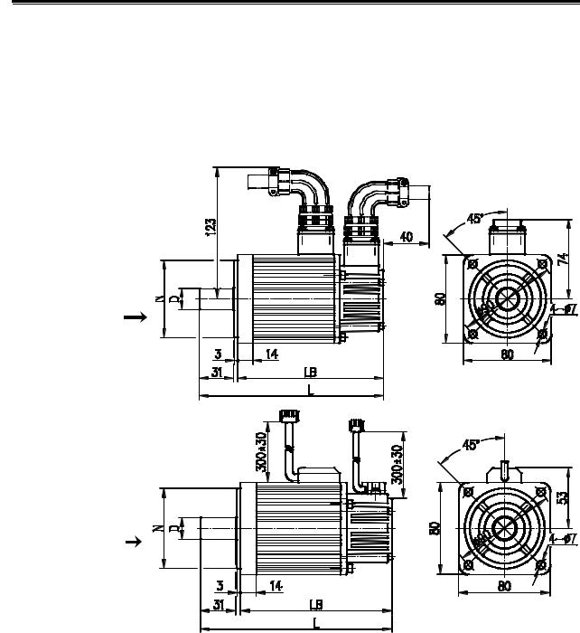
Chapter 2 Installation
CHAPTER 2 INSTALLATION
2.1Servo Motor
2.1.1Mounting Dimension of the Servo Motor
¾ For external dimensions and installation of 80SJT series motor, see figure 2-1, table 2-1.
Industrial (aviation)
Socket mount
Cable type
Fig. 2-1
Table 2-1
Type |
D(mm) |
N(mm) |
LB(mm) |
L(mm) |
80SJT—M024C (A□) |
φ190-0.013 |
φ700-0.03 |
171 |
206 |
80SJT—M024E(A□) |
φ190-0.013 |
φ700-0.03 |
171 |
206 |
80SJT—M032C(A□) |
φ190-0.013 |
φ700-0.03 |
189 |
224 |
80SJT—M032E(A□) |
φ190-0.013 |
φ700-0.03 |
189 |
224 |
19
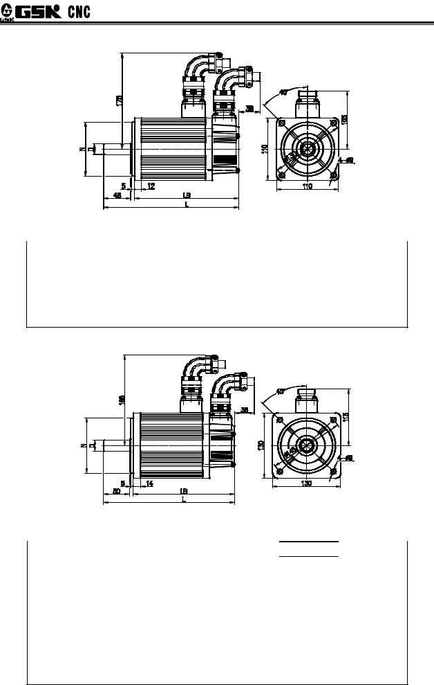
DAT Series AC Servo Drive Unit User Manual
¾ For external dimensions of 110SJT series motor, see figure 2-2, table 2-2.
Fig. 2-2
Table 2-2
Type |
D(mm) |
N(mm) |
LB(mm) |
L(mm) |
110SJT—M040D(A□) |
φ190-0.013 |
φ950-0.035 |
186 (237) |
241 (292) |
110SJT—M040E(A□) |
φ190-0.013 |
φ950-0.035 |
186 (237) |
241 (292) |
110SJT—M060D(A□) |
φ190-0.013 |
φ950-0.035 |
212 (263) |
267 (318) |
110SJT—M060E(A□) |
φ190-0.013 |
φ950-0.035 |
212 (263) |
267 (318) |
Note: LB, L values in the brackets are the length of corresponding motor that with safe brake.
¾ For external dimensions of 130SJT series motor, see figure 2-3, table 2-3.
|
Fig. 2-3 |
|
|
|
|
Table 2-3 |
|
|
|
|
|
|
LB(mm) |
|
Type |
D(mm) |
N(mm) |
L(mm) |
|
130SJT—M040D(A□) |
φ220-0.013 |
φ1100-0.035 |
168 (227) |
225 (284) |
130SJT—M050D(A□) |
φ220-0.013 |
φ1100-0.035 |
168 (227) |
225 (284) |
130SJT—M060D(A□) |
φ220-0.013 |
φ1100-0.035 |
176 (235) |
233 (292) |
130SJT—M075D(A□) |
φ220-0.013 |
φ1100-0.035 |
188 (247) |
245 (304) |
130SJT—M100B(A□) |
φ220-0.013 |
φ1100-0.035 |
208 (267) |
265 (324) |
130SJT—M100D(A□) |
φ220-0.013 |
φ1100-0.035 |
208 (267) |
265 (324) |
130SJT—M150B(A□) |
φ220-0.013 |
φ1100-0.035 |
238 (297) |
295 (354) |
130SJT—M150D(A□) |
φ220-0.013 |
φ1100-0.035 |
248 (307) |
305 (364) |
Note: LB, L values in the brackets are the length of corresponding motor that with safe brake.
20
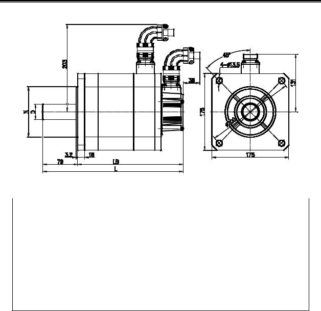
Chapter 2 Installation
¾ For external dimensions of 175SJT series motor, see figure 2-4, table 2-4.
Fig. 2-4
Table 2-4
Type |
D(mm) |
N(mm) |
LB(mm) |
L(mm) |
|
|
|
|
|
175SJT—M150D(A□) |
φ350+0.01 |
φ114.30-0.025 |
224 (291) |
303 (370) |
175SJT—M180B(A□) |
φ350+0.01 |
φ114.30-0.025 |
244 (311) |
323 (390) |
175SJT—M180D(A□) |
φ350+0.01 |
φ114.30-0.025 |
244 (311) |
323 (390) |
175SJT—M220B(A□) |
φ350+0.01 |
φ114.30-0.025 |
279 (346) |
358 (425) |
175SJT—M220D(A□) |
φ350+0.01 |
φ114.30-0.025 |
279 (346) |
358 (425) |
175SJT—M300B(A□) |
φ350+0.01 |
φ114.30-0.025 |
309 (382) |
388 (461) |
175SJT—M300D(A□) |
φ350+0.01 |
φ114.30-0.025 |
309 (382) |
388 (461) |
175SJT—M380B(A□) |
φ350+0.01 |
φ114.30-0.025 |
359 (432) |
438 (561) |
Note: LB, L values in the brackets are the length of corresponding motor that with safe brake.
2.1.2Servo Motor Installation
Servo motor installation, storage and transportation environment
Item |
Parameter and requirement |
|
|
|
|
Operation temperature |
0 40 |
|
|
|
|
Storage and transportation |
-40 70 |
|
temperature |
||
|
||
|
|
|
Operation humidity |
30% 95% no dewing |
|
|
|
|
Storage and transportation humidity |
≤95% 40 |
|
|
|
|
Atmosphere environment |
There is no corrosive or flammable gas, oil |
|
mist or dust etc. in the control cabinet |
||
|
||
|
|
|
Altitude |
Altitude of below 1000m |
|
|
|
21
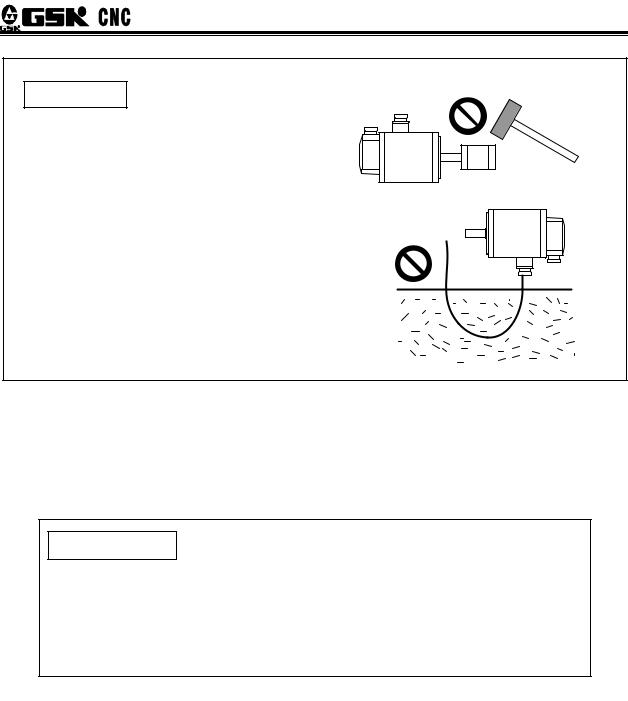
DAT Series AC Servo Drive Unit User Manual
Attentions
1. When install the belt pulley, do not strike the motor or the motor axis to avoid damage to internal encoder. Spiral insert and pull
out tools should be used for dismounting.
2. The servo motor can not bear axial and radial load. Spring coupling is recommended to connect the load.
3.Stop washer should be used to fix the motor to avoid motor loosening.
4.The motor mounting position should be protected against water and oil. The cable will bring water and oil to the motor if it immerses in water and oil.
Therefore, this situation should be prevented from happening.
2.2Servo Unit
The installation environment of the servo motor has direct effect on its functions and service life. Please install it correctly under the instructions below.
Item |
Parameter and requirement |
|
|
|
|
Operation temperature |
0 40 |
|
|
|
|
Storage and transportation temperature |
-40 70 |
|
|
|
|
Operation humidity |
30% 95% no dewing |
|
|
|
|
Storage and transportation humidity |
≤95% 40 |
|
|
|
|
Atmosphere environment |
There is no corrosive or flammable gas, oil |
|
mist or dust etc. in the control cabinet |
||
|
||
|
|
|
Altitude |
Altitude of below 1000m |
|
|
|
|
Vibration |
≤0.6G(5.9m/s2) |
|
|
|
|
Atmosphere pressure |
86kPa 106kPa |
|
|
|
22
 Loading...