


 This user manual describes all items concerning the operation of this CNC system in detail. However, it is impossible to give particular
descriptions for all unnecessary or unallowable operations due to length
limitation and products application conditions therefore, the items not
presented herein should be considered impractical or unallowable.
 Copyright is reserved to GSK CNC Equipment Co., Ltd. It is illegal for any organization or individual to publish or reprint this manual. GSK CNC
Equipment Co., Ltd. reserves the right to ascertain their legal liability.
I

GSK 25i Milling CNC System User Manual
Preface
Your Excellency,
We are honored by your purchase of this GSK 25i Milling Machining Center CNC System made by GSK CNC Equipment Co., Ltd.
This book is “PLC Programming and Connection” section of the User Manual Volume .
Special caution:
The power supply fixed on/in the cabinet is exclusively used for the CNC system made by GSK.
It can't be applied to other purposes, or else it may cause serious danger.
II

Volume PLC Programming and Connection
Warning and Precaution
 Accident may occur by improper connection and operation This system can only be operated by authorized and qualified personnel.
Please read this manual carefully before operation
Please read this manual and a manual from machine tool builder carefully before installation, programming and operation, and strictly observe the requirements.
This manual includes the precautions for protecting user and machine tool. The precautions are classified into Warning and Caution according to their bearing on safety, and supplementary information is described as Note. Read these Warnings, Caution and
Note carefully before operation.
Warning
User may be injured or equipment be damaged if operations instructions and procedures are not observed.
Caution
Equipment may be damaged if operation instructions or procedures are not observed.
Note
It is used to indicate the supplementary information other than Warning and Caution.
III

GSK 25i Milling CNC System User Manual
Announcement
●This manual describes various possibilities as much as possible. However, operations allowable or unallowable cannot be explained one by one due to so many possibilities that may involve with, so the contents that are not specially stated in this manual shall be considered as unallowable.
Caution
●Functions, technical indexes (such as precision and speed) described in this user manual are only for this System. Actual function deployment and technical performance of a machine tool with this CNC system are determined by machine tool builder’s design, so functions and technical indexes are subject to the user manual from machine tool builder.
●Refer to the user manual from machine tool builder for function and meaning of keys on control panel.
IV

Volume PLC Programming and Connection
Precautions
■Delivery and storage
●Packing box over 6 layers in pile is unallowed.
●Never climb the packing box, neither stand on it, nor place heavy objects on it.
●Do not move or drag the products by the cables connected to it.
●Forbid collision or scratch to the panel and display screen.
●Avoid dampness, insolation and drenching.
■Open-package inspection
●Confirm that the products are the required ones.
●Check that the products are not damaged in delivery.
●Confirm that the parts in packing box are in accordance with the order.
●Contact us in time if any inconsistence, shortage or damage is found.
■Connection
●Only qualified personnel can connect the System or check the connection.
●The System must be earthed, and the earth resistance must be less than 0.1Ω.
The earth wire cannot be replaced by zero wire.
●The connection must be correct and firm to avoid any fault or unexpected consequence.
●Connect with surge diode in the specified direction to avoid damage to the
System.
●Switch off power supply before plugging out or opening electric cabinet.
■Troubleshooting
●Only competent personnel are supposed to inspect the System or machine.
●Switch off power supply before troubleshooting or changing components.
●Check for fault when short circuit or overload occurs. Restart can only be done after troubleshooting.
●Frequent switching on/off of the power is forbidden, and the interval time should be at least 1 min.
V

GSK 25i Milling CNC System User Manual
Safety Responsibility
Manufacturer’s Responsibility
——Be responsible for the danger which should be eliminated and/or controlled on design and configuration of the provided CNC systems and accessories.
——Be responsible for the safety of the provided CNC systems and accessories.
——Be responsible for the provided information and advice for the users.
User’s Responsibility
——Be trained with the safety operation of CNC system and familiar with the safety operation procedures.
——Be responsible for the dangers caused by adding, changing or altering to the original CNC systems and the accessories.
——Be responsible for the failure to observe the provisions for operation, adjustment, maintenance, installation and storage in the manual.
All specifications and designs herein are subject to change without further notice.
This manual is reserved by end user.
We are full of heartfelt gratitude to you for supporting us in the use of GSK’s products.
VI

Volume PLC Programming and Connection
Contents
PLC PROGRAMMING................................................................................................................... |
1 |
||
PART 1 |
PROGRAMMING............................................................................................................. |
2 |
|
1 Sequence Program Creating Process ................................................................................... |
3 |
||
|
1.1 |
GSK25i PLC specifications..................................................................................................... |
3 |
|
1.2 |
What ’s a Sequence Program ................................................................................................ |
3 |
|
1.3 |
Assignment of interface specifications step 1 ............................................................... |
4 |
|
1.4 |
Establishment of ladder diagram step 2 ........................................................................ |
4 |
|
1.5 |
Sequence program debugging step 3 ............................................................................ |
4 |
2 Sequence Program.................................................................................................................. |
5 |
||
|
2.1 |
Execution process of sequence program ............................................................................. |
5 |
|
2.2 |
Repetitive cycle ........................................................................................................................ |
6 |
|
2.3 |
Priority of execution(1st level, and 2nd level)......................................................................... |
6 |
|
2.4 |
Sequence program structure.................................................................................................. |
7 |
|
2.5 |
Processing I/O (input/output) signals .................................................................................. |
8 |
|
2.6 |
Interlocking ........................................................................................................................... |
11 |
3 |
Address ............................................................................................................................... |
12 |
|
|
3.1 |
Machine →PLC address X ............................................................................................ |
13 |
|
3.2 |
PLC→machine side address Y ..................................................................................... |
15 |
|
3.3 |
PLC→CNC address G .................................................................................................... |
16 |
|
3.4 |
CNC→PLC address F .................................................................................................... |
17 |
|
3.5 |
Internal relay address R ................................................................................................. |
17 |
|
3.6 |
Address of keep relay K ................................................................................................. |
18 |
|
3.7 |
Addresses(A) for message selection .................................................................................. |
18 |
|
3.8 |
Address of counter C ...................................................................................................... |
19 |
|
3.9 |
Address of timer T ......................................................................................................... |
19 |
|
3.10 |
Address D of data table................................................................................................. |
20 |
|
3.11 |
Label address L ............................................................................................................. |
20 |
|
3.12 |
Subprogram numbers P ............................................................................................... |
20 |
4 PLC Basic Instruction ........................................................................................................... |
21 |
||
|
4.1 |
LD, LDI, OUT, OUTI command ............................................................................................ |
22 |
|
4.2 |
AND, ANI command............................................................................................................... |
22 |
|
4.3 |
OR, ORI command ................................................................................................................ |
23 |
|
4.4 |
ORB command ....................................................................................................................... |
23 |
|
4.5 |
ANB command ....................................................................................................................... |
24 |
5 PLC Functional Instructions................................................................................................. |
25 |
||
|
5.1 |
END1 1st level sequence program end ........................................................................ |
26 |
|
5.2 |
END2 2nd level sequence program end ....................................................................... |
27 |
|
5.3 |
TMR Timer ........................................................................................................................ |
27 |
|
5.4 |
TMRB fixed timer ............................................................................................................. |
28 |
|
5.5 |
TMRC timer ...................................................................................................................... |
29 |
|
5.6 |
DECB binary decode ...................................................................................................... |
31 |
|
5.7 |
CTR counter ..................................................................................................................... |
32 |
VII

|
|
GSK 25i Milling CNC System |
User Manual |
|
5.8 CTRC counter ................................................................................................................. |
34 |
|
|
5.9 |
ROTB binary rotation control ........................................................................................ |
36 |
|
5.10 |
CODB binary code conversion ................................................................................... |
38 |
|
5.11 |
MOVE logical product transfer .................................................................................... |
40 |
|
5.12 |
MOVOR data transfer after logical sum .................................................................... |
41 |
|
5.13 |
MOVB transfer of 1 byte ............................................................................................ |
42 |
|
5.14 |
MOVW transfer of 2 bytes ......................................................................................... |
43 |
|
5.15 |
MOVN transfer of an arbitrary number of bytes ....................................................... |
43 |
|
5.16 |
PARI parity check ......................................................................................................... |
44 |
|
5.17 |
DCNVB extended data conversion ............................................................................ |
45 |
|
5.18 |
COMPB binary compasion .......................................................................................... |
47 |
|
5.19 |
COIN coincidence check ............................................................................................. |
49 |
|
5.20 |
DSCHB data search ..................................................................................................... |
50 |
|
5.21 |
XMOVB binary indexed modifier data transfer ......................................................... |
51 |
|
5.22 |
ADDB(addition).................................................................................................................... |
53 |
|
5.23 |
SUBB binary subtraction ............................................................................................. |
55 |
|
5.24 |
MULB binary multiplication ......................................................................................... |
56 |
|
5.25 |
DIVB binary division ..................................................................................................... |
58 |
|
5.26 |
NUMEB definition of binary constant ......................................................................... |
60 |
|
5.27 |
DIFU Edge Up detection ............................................................................................. |
61 |
|
5.28 |
DIFD Edge Down detection ........................................................................................ |
62 |
|
5.29 |
SFT shift register .......................................................................................................... |
63 |
|
5.30 |
EOR EOR ...................................................................................................................... |
64 |
|
5.31 |
AND logical and ............................................................................................................ |
66 |
|
5.32 |
OR logical or .................................................................................................................. |
67 |
|
5.33 |
NOT logical not ............................................................................................................. |
69 |
|
5.34 |
COM common line control ........................................................................................... |
70 |
|
5.35 |
COME common line control end ................................................................................ |
71 |
|
5.36 |
JMP jump ....................................................................................................................... |
71 |
|
5.37 |
JMPE jump end ............................................................................................................ |
73 |
|
5.38 |
CALL conditional subprogram call ............................................................................. |
73 |
|
5.39 |
CALLU uncoditional subprogram call ........................................................................ |
74 |
|
5.40 |
JMPB label jump 1 ....................................................................................................... |
75 |
|
5.41 |
JMPC label jump 2 ....................................................................................................... |
76 |
|
5.42 |
LBL label ........................................................................................................................ |
76 |
|
5.43 |
SP subprogram ............................................................................................................. |
77 |
|
5.44 |
SPE end of a subprogram ........................................................................................... |
78 |
6 |
Ladder Writing Limit........................................................................................................... |
79 |
|
PART 2 |
FUNCTION ...................................................................................................................... |
80 |
|
1 |
Preparations for operatoin ............................................................................................. |
81 |
|
|
1.1 |
Emergency stop..................................................................................................................... |
81 |
|
1.2 |
CNC overtral signal ............................................................................................................... |
82 |
|
1.3 |
Alarm signal............................................................................................................................ |
83 |
|
1.4 |
Interlock................................................................................................................................... |
83 |
VIII

Volume PLC Programming and Connection
|
1.5 |
Operation mode selection..................................................................................................... |
84 |
2 |
Manual operation................................................................................................................... |
85 |
|
|
2.1 |
JOG feed/incremental feed................................................................................................... |
85 |
|
2.2 |
MPG / Step feed ..................................................................................................................... |
86 |
3 |
Reference Point Return......................................................................................................... |
88 |
|
|
3.1 |
Manual reference point return .............................................................................................. |
88 |
4 |
Automatic operation.............................................................................................................. |
91 |
|
|
4.1 |
Cycle start/feed hold .............................................................................................................. |
91 |
|
4.2 |
reset ......................................................................................................................................... |
94 |
|
4.3 |
Testing a program .................................................................................................................. |
95 |
|
4.4 |
Optional block skip................................................................................................................. |
98 |
|
4.5 |
Program restart....................................................................................................................... |
99 |
5 |
Feedrate Control.................................................................................................................. |
101 |
|
|
5.1 |
Rapid traverse rate .............................................................................................................. |
101 |
|
5.2 |
Override ................................................................................................................................. |
102 |
6 |
Auxiliary Function ............................................................................................................... |
104 |
|
|
6.1 |
Miscellaneous function ........................................................................................................ |
104 |
|
6.2 |
Auxiliary function lock .......................................................................................................... |
109 |
7 |
Spindle Speed Function...................................................................................................... |
111 |
|
|
7.1 |
Spindle speed control mode ............................................................................................... |
111 |
|
7.2 |
Spindle speed arrival signal................................................................................................ |
113 |
|
7.3 |
Rigid tapping ......................................................................................................................... |
114 |
8 |
Tool function........................................................................................................................ |
115 |
|
|
8.1 T command tool change......................................................................................................... |
115 |
|
9 Programming command ..................................................................................................... |
115 |
||
|
9.1 |
Custom macro program ......................................................................................................... |
115 |
CONNECTION ........................................................................................................................... |
118 |
||
1 |
GSK25i System Box Interface.......................................................................................... |
121 |
|
2 |
Operation panel interface................................................................................................. |
122 |
|
|
2.1 |
Sketch map of machine operation panel interface............................................................. |
122 |
|
2.2 |
GSK 25i CNC system communication interface XS21...................................................... |
122 |
|
2.3 |
Emergency stop power-on interface .................................................................................... |
122 |
3 |
I/O Interface ....................................................................................................................... |
123 |
|
4 |
Interconnection Graph ..................................................................................................... |
125 |
|
5 |
PC serial communication wire......................................................................................... |
126 |
|
6 |
MPG Wiring ....................................................................................................................... |
127 |
|
7 |
Operation Panel Signal Line ............................................................................................ |
129 |
|
8 |
Ethernet Communication Connection............................................................................. |
130 |
|
9 |
Connected with the Spindle Servo.................................................................................. |
132 |
|
10 Connected with the Spindle Converter ......................................................................... |
133 |
||
11 Connection Method of Z Brake, System Power-on Control ........................................ |
134 |
||
12 I/O Input, Output Signal.................................................................................................. |
135 |
||
|
12.1 Connection method of input signal..................................................................................... |
135 |
|
|
12.2 Connection method of output signal .................................................................................. |
136 |
|
IX

|
|
GSK 25i Milling CNC System |
User Manual |
|
12.3 |
Definition of input signal point ............................................................................................ |
137 |
|
12.4 |
Definition of output signal point.......................................................................................... |
139 |
APPENDIX ...................................................................................................................................... |
|
141 |
|
1 |
Signal table(address order)................................................................................................ |
141 |
|
2 |
Contour installation dimension drawing........................................................................... |
145 |
|
X
Volume PLC Programming and Connection
PLC PROGRAMMING
1

GSK 25i Milling CNC System User Manual
Part 1 Programming
2

Volume PLC Programming and Connection
1Sequence Program Creating Process
1.1GSK25i PLC specifications
Specification of GSK25i PLC are as follows(see Table 1-1):
Table 1-1
Specification |
GSK25i PLC |
||
Programming method language |
Ladder, command table |
||
Number of ladder level |
2 |
||
1st level execution period |
8ms |
||
Mean processing time of basic command |
0.5(μs/step) |
||
Program capacity |
12000 steps |
||
|
Command |
P 10 |
|
|
Functional command 44 |
||
|
|
|
|
|
|
||
Internal relay R |
1100 bytes R0 to R1099 |
||
Data table D |
1860 bytes D0 to D1859 |
||
Meter |
C |
400 bytes C0 to C399 100PCS |
|
Timer |
T |
200 bytes T0 to T199 100PCS |
|
PLC alarm detection A |
32 bytes(A0 to A31) |
||
Keep relay |
K |
32 bytes(K0 to K31) |
|
Label |
L |
9999 L1 L9999 |
|
Subprogram |
P |
512 P1 P512 |
|
|
|
||
Machine →PLC(X) |
128 bytes X0 to X127 |
||
PLC→machine (Y) |
128 bytes Y0 to Y127 |
||
CNC→PLC(F) |
256 bytes F0 to F255 |
||
PLC→CNC(G) |
256 bytes G0 to G255 |
||
1.2What ’s a Sequence Program
A sequence program is a program for sequence control of machine tools and other systems. The program is converted into a format to enable CPU execute encoding and arithmetic
processing, and stored into RAM. CPU reads out every instruction stored in the memory at a high-speed and execute the program by arithmetic operation
The sequence program is written firstly from ladder.
3

GSK 25i Milling CNC System User Manual
1.3Assignment of interface specifications step 1
After deciding the control object specification, calculate the number of input/output signal points, create the interface specification.
For input/output interface signals, see Chapter 4.
1.4Establishment of ladder diagram step 2
Express the control operations decided by 25i ladder diagram. For the timer, meter, etc, which cannot be expressed with the functional instructions.
The edited ladder should be converted into the corresponding PLC instruction i.e. instruction list to store.
1.5Sequence program debugging step 3
The sequence program can be debugged in two ways: 1 Debug by simulator
Instead of the machine, connect a simulator (consisting of lamps and switches). Switch ON/OFF stands for the input signal state of machine, lamp ON/OFF for the output signal state.
2 Actual operation debugging
Debug sequence program through operating the machine. Do measures against the unexpected affairs before debugging.
4

Volume PLC Programming and Connection
2Sequence Program
Since PLC sequence control handled by software and operates on principle difference from a general relay circuit, the sequence control method must be fully understood in order to design PLC sequence program.
2.1Execution process of sequence program
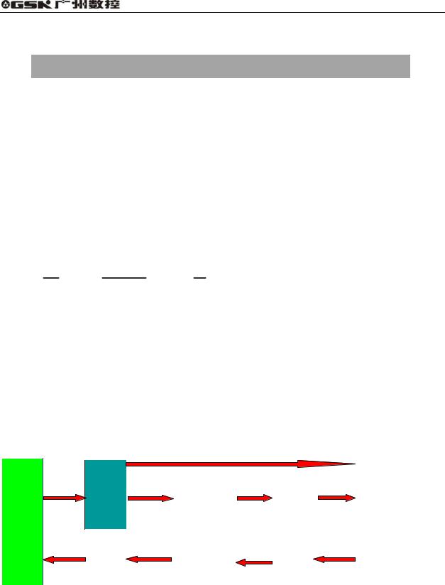
In general relay control circuit, each relay operates at approximately the same time, in the figure below for example, when relay A operate, the relay D and E operate at approximately the same time(when contacts B and C are off)., In PLC sequence control, each relay of circuit operates sequentially. When relay A operates, relay D operates, then relay E(see Fig.2-1). Thus each relay operates in sequence which can be written as a ladder diagram. (Programmed sequence).
A B
D
A C
E
Fig. 2-1(a)
Fig.2.1(b) and (c) illustrate operations varying from the relay circuit to PLC programs.
A C
B
A
C
Fig. 2-1(b)
A
C
A C
B
Fig.2-1(c)
5
GSK 25i Milling CNC System User Manual
(1)Relay circuit
In Fig. 2.1(b) and (c), the operations are the same. Turning on A turns on B and C. Turning on C turns off B.(2) PLC program
In Fig.2.1(b), as in the relay circuit, turning on A turns on B and C, and after one cycle of the PLC sequence, turns off B. But in Fig.2.1(c), turning on A turns on C, but does not turn on
2.2Repetitive cycle
The PLC executes the ladder diagram from the beginning to the end . When the ladder diagram ends, the program starts over from the beginning. This is called repetitive operation.
The execution time from the beginning to the end of the ladder diagram is called the sequence processing time. The shorter the process time is, the better the signal response becomes.
2.3Priority of execution(1st level, and 2nd level)
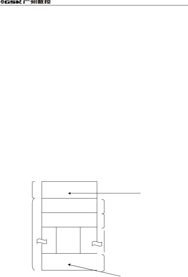
GSK25i PLC consists of two parts: 1st level sequence part, 2nd level sequence part. They have different execution period.
The 1st level sequence part operates every 8 ms, which can deal with the short pulse signal with high-speed response).
The 2nd level sequence part operates every 8*n ms. Here N is a dividing number for the 2nd level sequence part. The 2nd level sequence part is divided into V part, and every part is executed every 8ms.
END1
1st level sequence part
Specifies the end of the
1st level sequence part
Division 1
Division 2
2nd level sequence program
END2
|
|
Division n |
|
|
Specifies the end of the |
|
|
|
Fig. 2-2 |
2nd level sequence part |
|
6

Volume PLC Programming and Connection
GSK 25i PLC is solely executed in PLC-AVR single chip, and the first 1ms of each 8ms is the communication time of CNC reading or writing PLC data. The fifth 1ms is the time that the PLC receives the system control signal F, X and uploads the control result data G, Y parameter to the external I/O interface X, Y , except for the time responding the interruption to exchange the data, the PLC executes the ladder operation at the rest time.
|
|
|
|
|
8 ms |
|
|
|
|
|
|
|
8 ms |
|
|
|
|
|
|
|
|
|
8 ms |
|
|
|
|
||||||||||||||||||||
|
|
|
|
|
|
|
|
|
|
|
|
|
|
|
|||||||||
1st level |
|
3 ms |
|
|
|
|
3 ms |
|
|
|
|
|
|
3 ms |
|
||||||||
|
|
|
|
|
|
|
|
|
|
|
|
|
|
|
|
|
|
|
|
|
|
|
|
|
|
|
Division 1 |
|
|
|
|
|
Division 2 |
|
|
|
|
|
|
|
Division n |
||||||
|
|
|
|
|
|
|
|
|
|
|
|
|
|
|
|||||||||
|
|
|
|
|
|||||||||||||||||||
2nd level
CNC use
Fig. 2-3
After the last 2nd level sequence part (division n) is executed, the sequence program is executed
again from the beginning. Thus, when the dividing number is n, the cycle of execution is 8*n ms. The 1st level sequence operates every 8ms, and the 2nd level sequence every 8*n ms. If the steps of the 1st level sequence is increased, the steps of the 2nd level sequence operating within 4ms becomes
less, thereby increasing the dividing number and making the processing time longer. Therefore, it is desirable to program so as to reduce the 1st level sequence to a minimum.
2.4Sequence program structure
With the conventional PLC, a ladder program is described sequentially. By employing a ladder
language that allows structured programming, the following benefits are derived:
1.A program can be understood and developed easily
2.A program error can be found easily.
3.When an operation error occurs, the cause can be found easily.
Three major structured programming capabilities are supported:
1 Subprogram
A subprogram can consist of a ladder sequence as the processing unit.
Fig. 2-4
7
GSK 25i Milling CNC System User Manual
2) Nesting
The Ladder subprograms can call the other ladder subprogram to execute the job.
|
Main program |
|
Subprogram 1 |
|
|
Subprogram 2 |
|
|
|
|
|
||||
|
|
|
|
|
|
|
|
|
Job A |
|
|
Job A1 |
|
|
Job A11 |
|
|
|
|
|
|||
|
|
|
|
|
|
|
|
|
|
|
|
|
|
|
|
|
|
|
|
|
|
|
|
|
|
|
|
|
|
|
|
|
Job B |
|
|
|
|
|
Job A12 |
|
|
|
Job An |
|
|
||
|
|
|
|||||
|
|
|
|
|
|
|
|
|
|
|
|
|
|
|
|
|
|
|
|
|
|
|
|
|
|
|
|
|
|
|
|
Fig. 2-5
3) Conditional branch
The main program loops and checks whether conditions are satisfied. If a condition is satisfied, the corresponding subprogram is executed. If the condition is not satisfied, the subprogram is jumpped.
Main program |
Subprogram 1 |
|
|
|
|
Process 11 |
|||
|
|
Process 1 |
|
|
State 1 |
|
|||
|
|
|
||
|
|
|
|
|
|
|
|
|
|
|
|
|
|
|
|
|
|
|
|
|
|
|
|
Process 12 |
State 2 |
|
|
||
|
Process 2 |
|
|
|
|
|
|
||
|
|
|
|
|
|
|
|
|
|
|
|
|
|
|
|
Fig. 2-6 |
|
Process 13 |
|
|
|
|
||
|
|
|
|
|
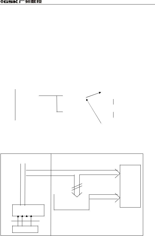
2.5Processing I/O (input/output) signals
Input signal processing:
CNC |
CNC—PLC |
PLC |
|
|
|
|
|
|
|
|
|
|
1st |
level |
|
|
|
|
sequence |
|
|
|
|
|
part |
|
|
|
2nd sequence part |
|
|
|
|
|
2nd |
level |
||
|
|
starting memory |
sequence |
||
|
|
|
|
||
2 |
nd |
sequence part |
part |
|
|
|
|
|
|||
input signal memory |
|
|
|||
Input signals from machine tool
8ms
IO interface
Fig. 2-7
8
Volume PLC Programming and Connection
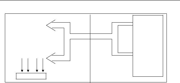
Output signal processing:
CNC |
PLC |
st |
|
|
|
1 level |
|
|
CNC—PLC |
||
|
|
sequence part |
|
|
Share memory |
|
|
|
|
|
2nd level |
|
|
|
|
output memory from |
|
||
|
sequence part |
||
machine tool |
|
|
|
8ms
IO interface
Fig. 2-8
2.5.1 Input signal processing
1 Input memory of NC
The input signals from NC are loaded in memory of NC and are transferred to the PLC at intervals of 8ms. Since the 1st level sequence part directly refer to these signal and process operations.
2 Input signal memory to machine tool
The input signal memory stores signals transferred from the machine tool at intervals of 8ms period. Since the 1st level sequence part directly refer to these signal and process operations.
3 2nd level input signal memory
The 2nd level input signal memory is also called as 2nd level synchronous input signal memory. The stored signals are processed by the 2nd level sequence part. State of the signals set this memory synchronizes with that of 2nd level sequence part.
Input memory Signals from NC and machine tool are transferred to the 2nd level input signal memory only at the beginning of execution of the 2nd level sequence part. Therefore, the state of the 2nd level synchronous input signal memory does not change from the beginning to end of the execution of the 2nd level sequence part.
2.5.2 Output signal processing
1 NC output memory
The output signals are transferred form the PLC to the NC output memory at intervals of 8ms.
2 Output signals to machine tool
Output signal to the machine tool from PLC output signal memory to the machine tool at intervals of 8ms.
9
GSK 25i Milling CNC System User Manual
Note:
The state of the NC input memory, NC output memory, input signals from machine, input/output memory signals to machine can be checked by using the PC self-diagnosis function. The self-diagnosis number specified is the address number used by the sequence program.
2.5.3 Synchronous processing the short pulse signal
1st program can process the short pulse signal. When the short pulse signal change is less than 8ms, i.e.when the system executes the 1st program, the input signal state can change to cause the followings.
Fig. 2-9
When A 0 and B1 1 A becomes 1, at the moment, the system executes the next ladder statement to make B2 1. so, B1 and B2 become 1.
A
R
R
B1
R
B2
END1
Fig. 2-10
When the medium relay R synchronously processes the signal A, B1, B2 are not 1 at the same time.
10
Volume PLC Programming and Connection
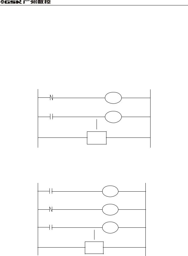
2.5.4 Difference state of signals between 1st level and 2nd level
The state of the same input signal may be different in the 1st level and 2nd level sequences. That is, at 1st level, processing is performed using input signal memory and at 2nd level, processing is performed using the 2nd level synchronous input signal memory. Therefore, it is possible for a 2nd level sequence execution at the worst, compared with a 1st level input signal.
This must be kept in mind when writing the sequence program.
2nd division of 2nd level sequence part
Fig. 2-11
When the processing is 1st 8ms, A=1, and B=1 after 1st sequence part is executed. At the same time, 2nd sequence part is started to execute A=1 is stored to the 2nd sequence part and the 1st division of 2nd sequence part is executed.
When the processing is 2nd 8ms, A=0, and B=0 after 1st sequence part is executed. And then 2nd division of 2nd sequence part is executed, at this time, A is still 1. So C=1.
So, B and C are different.
2.6Interlocking
Interlocking is externally important in sequence control safety.
Interlocking with the sequence program is necessary. However, interlocking with the end of the electric circuit in the machine tool magnetic cabinet must not be forgotten. Even though logically interlocked with the sequence program (software), the interlock will not work when trouble occurs in the hardware used to execute the sequence program. Therefore, always provide an interlock inside the machine tool magnetic cabinet panel to ensure operator safety and to protect the machine from damage.
11
GSK 25i Milling CNC System User Manual
3 Address
An address shows a signal location. Addresses include input/output signals with respect to the machine, the input/output signals with respect to the CNC, the internal relays, the meters, the keep relays, and data table. Each address consists of an address number and a bit number. Its serial number regulations are as follows:
Address regulations:
The address comprises the address type, address number and the bit number in the format as shown below:
Type: including X, Y, R, F, G K, A, D ,C, T
Address number: decimal serial number stands for one byte.
Bit number: octal serial number, 0 7 stands for 0 7 bit of byte of front address number
GSK25i PLC address type is as follows Fig.3-1
Emergency stop, jump and other high-speed signals
|
|
|
|
|
|
|
|
|
|
|
Machine to PLC |
X |
|
|
|
|
PLC to NC |
|
|||
|
|
|
G |
|
||||||
|
|
|
|
|
|
|
|
|
25i |
|
MTInput signal |
|
|
|
Nesting |
|
|
|
|||
|
|
|
|
|
|
|
CNC |
|||
PLC to machine |
|
|
|
|
|
|
NC to PLC |
|||
|
Y |
|
PLC |
|
F |
|||||
|
|
|
|
|||||||
Output signal |
|
|
|
|
|
|
|
|
||
|
|
|
|
|
|
|
|
|
|
|
|
|
|
|
|
|
|
|
|
|
|
Fig. 3-1
12

Volume PLC Programming and Connection
Table 3-1
Address |
Address explanation |
Address range |
X |
machine→PLC(128 bytes) |
X0 X127 |
Y |
PLC→machine(128 bytes) |
Y0 Y127 |
F |
CNC→PLC(256 bytes) |
F0 F255 |
G |
PLC→CNC(256 bytes) |
G0 G255 |
R |
Internal relay(1100 bytes) |
R0 R1099 |
D |
Data register(1860 bytes) |
D0 D1859 |
C |
Counter (400 bytes) |
C0 C 399 |
T |
Timer (200 bytes) |
T0 T199 |
A |
Timer preset data register (32 bytes) |
A0 A31 |
K |
Keep relay 32 bytes |
K0 K31 |
3.1Machine →PLC address X
X addresses of GSK25i PLC are divided into two:
1.X addresses are assigned to IO input interface.
2.X addresses are assigned to the input press keys on MDI panel.
3.X addresses are assigned to other external interfaces, such as the spindle, MPG control signal input.
3.1.1Assignment of IO module X address
The addresses are from X9 to X119. Its type is INT8U, 111 types.
The signal specification of X addresses can be customized by customer according to the actual
operation. X addresses are used to connect the machine tool with the ladder. For the initial definition
of input address, see Chapter Four Connection.
3.1.2Assignment of MDI panel X address
The addresses are from X0 to X8, 9 bytes. They correspond to the press keys on MDI panel. The corresponding relationship between them and the press keys on the standard panel is as Fig. 3-2:
13

GSK 25i Milling CNC System User Manual
|
|
Table 3-2 |
|
INPUT KEY ON |
PLC |
INPUT KEY ON |
PLC |
OPERATION PANEL |
ADDRESS |
OPERATION PANEL |
ADDRESS |
Auto mode |
X0.0 |
-Z |
X3.5 |
Edit mode |
X0.1 |
-4 |
X3.6 |
MDI mode |
X0.2 |
-5 |
X3.7 |
Manual mode |
X0.3 |
Spindle CW |
X4.0 |
MPG mode |
X0.4 |
Spindle stop |
X4.1 |
Zero mode |
X0.5 |
Spindle CCW |
X4.2 |
DNC mode |
X0.6 |
Spindle orientation |
X4.3 |
USER1 |
X0.7 |
F0 0.001 |
X4.4 |
Single block |
X1.0 |
25% 0.01 |
X4.5 |
Jump |
X1.1 |
50% 0.1 |
X4.6 |
Machine lock |
X1.2 |
100% 1 |
X4.7 |
Auxiliary lock |
X1.3 |
|
|
+4 |
X1.4 |
|
|
+Z |
X1.5 |
|
|
-Y |
X1.6 |
Tool magazine infeed |
X5.3 |
+5 |
X1.7 |
Tool retraction |
X5.4 |
Dry run |
X2.0 |
Tool change manipulator |
X5.5 |
Overtravel release |
X2.1 |
Tool magazine CW |
X5.6 |
Optional stop |
X2.2 |
Tool magazine zero |
X5.7 |
Program restart |
X2.3 |
Clamp/release |
X6.0 |
+X |
X2.4 |
USR2 |
X6.1 |
Rapid |
X2.5 |
USR3 |
X6.2 |
Step |
X2.6 |
USR4 |
X6.3 |
-X |
X2.7 |
Feed hold |
X6.4 |
Cooling |
X3.0 |
Cycle start |
X6.5 |
Lubricating |
X3.1 |
Tool magazine CCW |
X6.6 |
Chip removal |
X3.2 |
Feedrate override, up to |
X7.0-X7.4 |
|
24-gear(no output light) |
|
|
|
|
|
|
Working light |
X3.3 |
Spindle override, up to |
X8.0-X8.3 |
|
16-gear no output light |
|
|
|
|
|
|
+Y |
X3.4 |
Emergency stop |
X8.4 |
14

Volume PLC Programming and Connection
3.1.3 MPG signal input X address
Table 3-3
|
MPG signal input |
PLC address |
HDC0_STP MPG emergency stop signal |
X121.0 |
|
HDC0_MX100 MPG federate override |
X120.0 |
|
HDC0_MX10 MPG federate override |
X120.1 |
|
|
|
|
HDC0_MX1 |
MPG federate override |
X120.2 |
HDC0_5 |
5th axis |
X120.3 |
HDC0_4 |
4th axis |
X120.4 |
HDC0_Z |
Z axis |
X120.5 |
HDC0_Y |
Y axis |
X120.6 |
|
|
|
HDC0_X |
X axis |
X120.7 |
|
|
|
3.2PLC→machine side address Y
Y addresses of GSK25i PLC are divided into three:
1.Y addresses are assigned to IO input interface.
2.Y addresses are assigned to the indicators on MDI panel.
3.Y addresses are assigned to the indicators on MPG.
3.2.1 Y address of I/O output interface
The addresses are from Y8 to Y119. Its type is INT8U, 112 types.
The signal specification of Y addresses can be customized by customer according to the actual operation. Y addresses are used to connect the machine tool with the ladder. For the initial definition of input address, see Chapter Four Connection.
3.2.2 Assignment of IO module Y address
The addresses are from Y0 to Y7, 8 bytes. They correspond to the indicators on MDI panel, and their signal definitions cannot be changed by user.
Addresses and indicators are as follows Table.3-4:
15

GSK 25i Milling CNC System User Manual
Table 3-4
OUTPUT KEY ON |
PLC |
OUTPUT KEY ON |
PLC |
OPERATION PANEL |
ADDRESS |
OPERATION PANEL |
ADDRESS |
Auto key indicator |
Y0.0 |
-Z key indicator |
Y3.5 |
Edit key indicator |
Y0.1 |
-4 key indicator |
Y3.6 |
MDI key indicator |
Y0.2 |
-5 key indicator |
Y3.7 |
Manual key indicator |
Y0.3 |
Spindle CW key indicator |
Y4.0 |
MPG key indicator |
Y0.4 |
Spindle stop key indicator |
Y4.1 |
Zero key indicator |
Y0.5 |
Spindle CCW key indicator |
Y4.2 |
DNC key indicaor |
Y0.6 |
Spindle orientation key indicator |
Y4.3 |
USER1 key indicaor |
Y0.7 |
F0 0.001 key indicator |
Y4.4 |
Single block key indicaor |
Y1.0 |
25% 0.01 key indicator |
Y4.5 |
Jump key indicator |
Y1.1 |
50% 0.1 key indicator |
Y4.6 |
Machine lock indicator |
Y1.2 |
100% 1 key indicator |
Y4.7 |
Auxiliary lock indicator |
Y1.3 |
Tool magazine infeed key indicator |
Y5.3 |
+4 key indicator |
Y1.4 |
Tool retraction key indicator |
Y5.4 |
+Z key indicator |
Y1.5 |
Tool change key indicator |
Y5.5 |
-Y key indicator |
Y1.6 |
Tool magazine CW key indicator |
Y5.6 |
+5 key indicator |
Y1.7 |
Tool magazine zero key indicator |
Y5.7 |
Dry run key indicator |
Y2.0 |
Clamp/release tool key indicator |
Y6.0 |
Overtravel release key indicator |
Y2.1 |
USR2 key indicator |
Y6.1 |
Optional stop key indicator |
Y2.2 |
USR3 key indicator |
Y6.2 |
Program restart key indicator |
Y2.3 |
USR4 key indicator |
Y6.3 |
+X key indicator |
Y2.4 |
Feed hold key indicator |
Y6.4 |
Rapid key indicator |
Y2.5 |
Cycle start key indicator |
Y6.5 |
Step key indicator |
Y2.6 |
Tool magazine CCW key indicator |
Y6.6 |
-X key indicator |
Y2.7 |
X zero return indicator |
Y7.0 |
Cooling key indicator |
Y3.0 |
Y zero return indicator |
Y7.1 |
Lubricating key indicator |
Y3.1 |
Z zero return indicator |
Y7.2 |
Chip removal key indicator |
Y3.2 |
4th zero return indicator |
Y7.3 |
Working light key indicator |
Y3.3 |
5th zero return indicator |
Y7.4 |
+Y key indicator |
Y3.4 |
System alarms |
Y7.6 |
3.2.3 MPG signal light output
MPG signal light output |
Y120.0 |
3.3PLC→CNC address G
Addresses are from G0 to G255. Type: INT8U,256 bytes. G addresses are the signals from PLC to NC, and these signals have been defined in designing the CNC system and cannot be modified.
16
Volume PLC Programming and Connection
The concrete is referred to Appendix 1.
3.4CNC→PLC address F
A ddresses are from F0 to F255. Type: INT8U,256 bytes. F addresses are the signals from NC to
PLC, and these signals have been defined in designing the CNC system and cannot be modified. The
concrete is referred to Appendix 1.
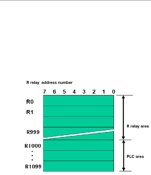
3.5Internal relay address R
The address area is cleared to zero when the power is turned on.
Type: INT8U, with 1100 bytes.
Fig. 3-2
Note: the addresses from R1000 are used by PLC. For example: ADDB, SUBB, COMB functional command operation result are output to the register:
#7 |
#6 |
#5 |
#4 |
#3 |
#2 |
#1 |
#0 |
||
R1000 |
|
|
Overflow |
|
|
|
|
Negative |
Zero |
Fig. 3-3
17

GSK 25i Milling CNC System User Manual
3.6Address of keep relay K
The area is used for the keep relays and PLC parameters. Since this area is nonvolatile, the
content of the memory do not disappear even when the power is turned off.
Type: INT8U, with 32 bytes
Fig. 3-4
3.7Addresses(A) for message selection
The address area is cleared to zero when the power is turned on.
Type: INT8U, with 32 bytes.
Fig. 3-5
18
Volume PLC Programming and Connection
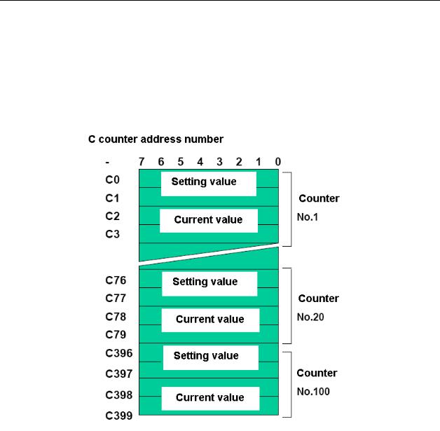
3.8Address of counter C
The area is used as storing current counting value in meter.
Type: 400 bytes.
C1 C100: count range: 0 65535, can set increase/reducing count, and the counting value does not disappear even when the power is turned off.
Fig. 3-6
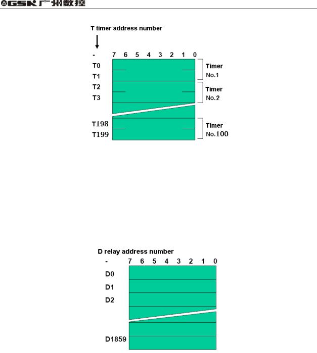
3.9Address of timer T.
Type: 200 bytes.
T1 T100 The timing value does not disappear even when the system is turned off.
19
GSK 25i Milling CNC System User Manual
Fig. 3-7
3.10Address D of data table
Each data register has 8-bit, two continuous data registers can store 16-bit data, four continuous data registers can store 32-bit data.
The content of the memory do not disappear even when the power is turned off.
Number of data table D0 D1859 1860 bytes.
Fig. 3-8
3.11Label address L
Label addresses are used to specify jump destination labels and LBL labels in JMPB instructions. Range: L0 L9999
3.12Subprogram numbers P
Subprogram numbers are used to specify jump destination subprogram labels and SP instruction subprogram labels in CALL instruction.
Range: P0 P511.
20
 Loading...