


Preface
 In this user manual we try to describe the matters concerning the operation of this GS Series Spindle Servo Drive Unit to the greatest extent. However, it is impossible to give particular descriptions for all unnecessary or unallowable operations due to length limitation and products application conditions; Therefore, the items not presented herein should be regarded as “impossible” or “unallowable”.
 Copyright is reserved to GSK CNC Equipment Co., Ltd. It is illegal for any organization or individual to publish or reprint this manual. GSK CNC Equipment Co., Ltd. reserves the right to ascertain their legal liability.
I

GS Series Spindle Servo Drive Unit User Manual
Preface
Dear customers,
We are honored and thankful for your purchase of this GSK product! This manual describes items concerning GS Series Spindle Servo
Drive Unit in detail, such as performance, installation, connection, commissioning, usage and maintenance etc.
To ensure safe and effective running, please read this manual carefully before installation and operation.
To avoid injury to operators and other personnels, and damage to the mechanical equipments, please pay special attention to the following warning signs when reading this manual.
 Danger Mal-operation may lead to serious injury or death.
 Caution Mal-operation may lead to minor injury or physical damage.
Notice It indicates a potential situation which, if not avoided, may result in an undesirable result or state.
 It reminds users of the important instructions and requirements.
Forbidden (definitely cannot be done)
Compulsive (must be done)
II
Caution
 Danger
Tighten all terminals of main circuits properly.
!result in loose connection which can easily lead to spark hazard or even fire disaster.Failure to observe it may
Make sure that the input power is OFF before wiring.
! |
Failure to observe it may |
result in electric shock. |
Wire layout or overhaul should be done by electrical engineering
technician.
!Failure to observe it may result in electric shock or fire disaster.
Wiring should be performed according to the method described in User
Manual.
!Failure to observe it may result in equipment damage and electric shock.
DO NOT operate the switch with wet hand.
Failure to observe it may result in electric shock.
DO NOT open the terminal strip cover after power-on or in running state.
Failure to observe it may result in electric shock.
Mount the drive unit on noncombustible, and keep it far away from inflammables.
!Failure to observe it may result in fire disaster.
Make sure the grounding terminal PE of servo unit is well grounded.
!Failure to observe it may result in electric shock.
Moving, checking, and maintaining equipments or wiring should be
performed 5 minutes after power-off.
!Failure to observe it may result in electric shock.
DO tighten the power terminals and motor output terminals.
!Failure to observe it may result in fire disaster.
DO NOT put hand into servo unit.
Failure to observe it may result in electric shock.
DO NOT touch the wiring terminals of servo unit main circuits.
Failure to observe it may result in electric shock.
III
GS Series Spindle Servo Drive Unit User Manual
 Danger
The servo unit may be activated suddenly after power resumption, so DO NOT operate the servo motor axes connection device immediately.
Failure to observe it may result in personal injury.
DO NOT place cables beside sharp edges, and AVOID heavy load or tension imposing on cables.
Failure to observe it may result in electric shock, equipment fault or damage.
DO NOT prevent radiation or put objects in cooling fan or radiator.
Failure to observe it may result in equipment damage or fire disaster.
DO NOT perform live-wire operation on the servo drive device when the cover of terminal strip is taken apart.
Failure to observe it may result in electric shock.
 Caution
IV

Caution
 Caution
DO NOT connect power input wires R, S, T to motor output wire terminals U, V, W.
Failure to observe it may result in device damage.
DO NOT touch the radiation device of motor and servo unit when they are running, because high temperature may be caused.
Failure to observe it may result in scald.
DO NOT alter, dismantle or repair the drive unit without authorization.
Failure to observe it may result in device damage.
DO NOT turn ON/OFF the input power frequently.
Failure to observe it may result in device damage.
DO NOT make excessive changes to parameters.
Failure to observe it may result in device damage.
The scrapped components of servo unit should be handled as industrial waste and cannot be reused.
Failure to observe it may result in accident.
V

GS Series Spindle Servo Drive Unit User Manual
Safety Responsibility
Manufacturer’s Responsibility
——Be responsible for the danger which should be eliminated and/or controlled on design and configuration of the provided Servo Drive Unit and accessories.
——Be responsible for the safety of the provided Servo Drive Unit and accessories. ——Be responsible for the provided information and advice for the users.
User’s Responsibility
——Be trained with the safety operation of Servo Drive Unit and familiar with the safety operation procedures.
——Be responsible for the dangers caused by adding, changing or altering to the original Servo Drive Unit and the accessories.
——Be responsible for the failure to observe the provisions for operation, adjustment, maintenance, installation and storage in the manual.
This manual is reserved by end user.
We are full of heartfelt gratitude to you for supporting us in the use of GSK’s products.
VI

Contents
|
Contents |
|
CHAPTER I INSTRUCTION...................................................................................................................... |
1 |
|
1.1 |
Basics .............................................................................................................................................. |
1 |
1.2 |
Product Confirmation ....................................................................................................................... |
6 |
1.2.1 Instruction of AC Spindle Servo Motor Model........................................................................... |
6 |
|
1.2.2 Instruction of Spindle Servo Unit .............................................................................................. |
7 |
|
1.2.3 Overall Appearance of Spindle Servo Unit ............................................................................... |
8 |
|
1.3 |
Technical Specification .................................................................................................................. |
11 |
1.3.1 Technical Specification of Spindle Motor................................................................................ |
11 |
|
1.3.2 Technical Specification of AC Spindle Servo Unit .................................................................. |
13 |
|
1.4 |
Ordering Guidelines....................................................................................................................... |
15 |
1.4.1 Model Selection Process ........................................................................................................ |
15 |
|
1.4.2 Examples ................................................................................................................................ |
15 |
|
1.4.3 Standard Ex-factory Accessories............................................................................................ |
17 |
|
CHAPTER II INSTALLATION/MOUNTING ............................................................................................. |
21 |
|
2.1 |
Spindle Servo Motor ...................................................................................................................... |
21 |
2.1.1 Dimensions for Spindle Motor Installation .............................................................................. |
21 |
|
2.1.2 Installation of Spindle Motor ................................................................................................... |
23 |
|
2.2 |
Spindle Servo Unit ......................................................................................................................... |
25 |
2.2.1 Installation Dimension............................................................................................................. |
26 |
|
2.2.2 Installation Intervals ................................................................................................................ |
28 |
|
CHAPTER III CONNECTION .................................................................................................................. |
31 |
|
3.1 |
Connection of Peripheral Equipments ........................................................................................... |
32 |
3.2 |
Connection of Main Circuit ............................................................................................................ |
37 |
3.2.1 Connection.............................................................................................................................. |
37 |
|
3.2.2 Wiring of Main Circuit.............................................................................................................. |
38 |
|
3.2.3 Servo Motor Connection Instruction ....................................................................................... |
38 |
|
3.3 |
Connection of Control Signal......................................................................................................... |
40 |
3.3.1 CN1 Control Signal ................................................................................................................. |
40 |
|
3.3.2 Speed Command Input........................................................................................................... |
43 |
|
3.3.3 Position Command Input ........................................................................................................ |
44 |
|
3.3.4 Digital Input ............................................................................................................................. |
47 |
|
3.3.5 Digital Output .......................................................................................................................... |
49 |
|
3.3.6 Position Signal Output ............................................................................................................ |
52 |
|
3.4 |
Connection of Position Feedback Signal....................................................................................... |
53 |
3.4.1 Motor Encoder Position Feedback Signal Interface CN2 ....................................................... |
53 |
|
VII

|
GS Series Spindle Servo Drive Unit |
User Manual |
3.4.2 2nd Position Feedback Signal Interface CN3 ........................................................................ |
57 |
|
3.4.3 Interface CN3 of GS Series MDR Products ........................................................................... |
58 |
|
3.5 GSK-CAN Communication............................................................................................................ |
59 |
|
3.6 |
Connection in Different Working Mode ......................................................................................... |
60 |
3.6.1 Connection in Speed Mode.................................................................................................... |
60 |
|
3.6.2 Connection in Position Mode ................................................................................................. |
63 |
|
3.6.3 Connection in Speed/Position Mode...................................................................................... |
65 |
|
CHAPTER IV DISPLAY AND OPERATION ........................................................................................... |
69 |
|
4.1 |
Operation Panel ............................................................................................................................ |
69 |
4.2 |
Display Menu ................................................................................................................................ |
70 |
4.3 |
Status Monitoring .......................................................................................................................... |
71 |
4.4 |
Parameter Setting ......................................................................................................................... |
74 |
4.5 |
Parameter Management ............................................................................................................... |
75 |
CHAPTER V GENERAL COMMISSIONING.......................................................................................... |
77 |
|
5.1 |
Running in Manual/JOG Mode...................................................................................................... |
78 |
5.1.1 Manual Running ..................................................................................................................... |
79 |
|
5.1.2 JOG Running.......................................................................................................................... |
80 |
|
5.2 |
Running in Speed Mode ............................................................................................................... |
81 |
5.2.1 Analog Speed Command ....................................................................................................... |
81 |
|
5.2.2 Internal Speed Command ...................................................................................................... |
84 |
|
5.3 |
Running in Position Mode ............................................................................................................. |
85 |
5.4 |
Running in Speed/Position Mode ................................................................................................. |
87 |
CHAPTER VI FUNCTIONALITY TESTING............................................................................................ |
91 |
|
6.1 |
Instruction for Basic Performance Parameters Setting................................................................. |
91 |
6.1.1 Setting Methods ..................................................................................................................... |
91 |
|
6.1.2 Three Gains of Closed-Loop Control ..................................................................................... |
93 |
|
6.2 |
Switching of Motor Rotation Directions......................................................................................... |
94 |
6.3 |
Braking Stop.................................................................................................................................. |
96 |
6.4 |
Testing in Position Mode............................................................................................................... |
97 |
6.4.1 Electronic Gear Ratio of Position Command ......................................................................... |
97 |
|
6.4.2 Position Arrival Signal ............................................................................................................ |
98 |
|
6.4.3 Position Deviation Clear......................................................................................................... |
99 |
|
6.4.4 Pulse Command Inhibition ..................................................................................................... |
99 |
|
6.5 |
Testing in Speed Mode ............................................................................................................... |
100 |
6.5.1 Orientation Function............................................................................................................. |
100 |
|
6.5.2 Adjustment of Analog Commands ....................................................................................... |
105 |
|
6.5.3 Speed Arrival Signal............................................................................................................. |
106 |
|
VIII

Contents
6.5.4 Zero Speed Clamp................................................................................................................ |
107 |
|
6.5.5 Speed Command Electronic Gear Ratio .............................................................................. |
108 |
|
6.6 |
Spindle Clamp Interlock Signal (BREF)....................................................................................... |
109 |
CHAPTER VII PARAMETERS .............................................................................................................. |
111 |
|
7.1 |
Parameter List ............................................................................................................................. |
111 |
CHAPTER VIII ABNORMALITIES AND REMEDIES ............................................................................ |
123 |
|
8.1 |
Remedies for Normal Faults........................................................................................................ |
123 |
8.1.1 Speed Mode ............................................................................................................................. |
123 |
|
8.1.2 Position Mode ....................................................................................................................... |
125 |
|
8.1.3 Others ................................................................................................................................... |
126 |
|
8.2 |
Alarms and Remedies ................................................................................................................. |
128 |
8.3 |
Inspection and Maintenance........................................................................................................ |
133 |
APPENDIX A Model Code Parameters and Feed Servo Motors Table................................................ |
135 |
|
APPENDIX B Peripheral Equipments ................................................................................................... |
136 |
|
B.1 Circuit Breaker and Contactor (essential) ................................................................................... |
136 |
|
B.2 Three-phase AC filter (recommended)........................................................................................ |
136 |
|
B.3 AC Reactor (recommended) ....................................................................................................... |
137 |
|
APPENDIX C BRAKING RESISTOR SELECTION............................................................................... |
138 |
|
APPENDIX D CONNECTION DIAGRAMS BETWEEN SPINDLE SERVO UNIT AND CNC SYSTEM |
||
............................................................................................................................................................... |
|
141 |
IX
Chapter I Instruction
CHAPTER I INSTRUCTION
1.1Basics
¾Fundamental principles and circuits of spindle servo drive
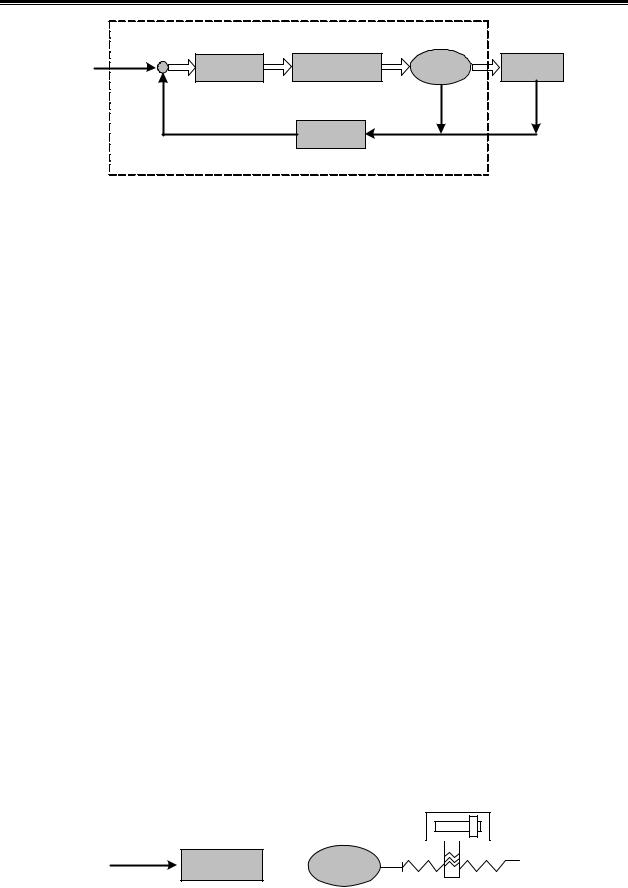
The spindle servo drive is composed of spindle servo unit and spindle servo motor (three-phase AC asynchronous servo motor, hereinafter called servo motor). The servo unit rectifies AC to DC, and by controlling the ON/OFF of power transistor, it generates current approximated to sinewave whose phase difference is 120° in the three-phase stator winding of servo motor (i.e., DC-AC). Thus, a magnetic field is created in the servo motor, and the rotator generates current as a result of magnetic field induction. The interaction between the inductive current and magnetic field leads to the generation of a torque which causes the rotator to work. Higher frequency of current which goes through the servo motor winding corresponds to quicker servo motor speed; the larger current amplitude corresponds to larger output torque of the servo motor (torque= force × arm length). Figure 1-1 shows the main circuit of servo unit; PG represents the encoder.
Fig. 1-1 Main circuit of spindle servo unit
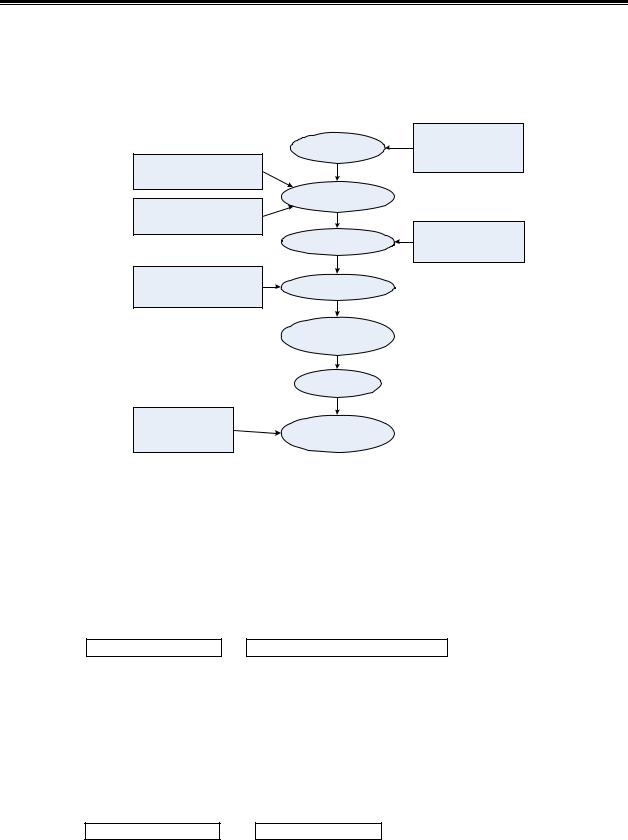
¾Basic structure of spindle servo drive
The servo unit receives speed (or position) commands from control device (also called upper computer) such as CNC system. It controls the frequency and magnitude of current which goes through the servo motor winding, so that the rotation speed (or angle) of servo motor rotator can be approximated to the speed (or position) command value, and the difference between actual rotation speed (or angle) and commanded value can be detected. By constantly adjusting the frequency and magnitude of current, the servo unit can limit the differences within the required range. Figure 1-2 shows the basic structure of spindle servo drive.
1
GS Series Spindle Servo Drive Unit User Manual
|
Specify |
|
|
|
|
CNC |
|
Control |
Power Drive |
Motor |
Machine |
|
|||||
System |
|
Unit |
Unit |
||
|
|
|
|||
|
|
|
|
|
|
Feedback
Detection
Spindle Servo Drive
Fig. 1-2 Basic structure of spindle servo drive
¾General concept of control
zControl: A process of the characteristics (such as speed) of an object (such as servo motor) reaching or approximating to the desired value is called CONTROL. The object herein is called PLANT; and its characteristic is called CONTROLLED VARIABLES; the unit which realizes the control is called CONTROL UNIT; the process of receiving the desired value by the control unit is called SPECIFY; the process of inputting and reacting to controlled variable is called FEEDBACK; the unit that detects the controlled variables is called FEEDBACK UNIT; the feedback can be divided into positive feedback (same direction) and negative feedback( reversed direction) according to the controlled variables and output direction. The drive is composed of plant, feedback unit and control unit. There are two kinds of drives: open-loop control device and closed-loop control device. They are distinguished by the absence/presence of feedback unit and its position in drive. The closed-loop control device described in this manual is negative feedback closed-loop control device.
In this manual, the spindle servo unit is the control unit; the plant is the servo motor; the motor rotation speed (or angle) is the controlled variable; the encoder is the feedback unit; the speed feedback is realized when actual speed is detected by encoder for speed control. Spindle servo unit belongs to closed-loop control device.
zOpen-loop control device: Feedback unit is absent in the control device, so the actual controlled variables do not affect the output of control unit. Take stepper motor drive for example: after the servo unit outputs the phase sequence changes of current, the rotator of stepper motor should follow the change; however, since there is no feedback unit, the rotator may not catch up with the changes due to overload or fast acceleration/deceleration, this is the so-called “out-of-synchronism”. Shown in Figure 1-3.
Machine
Specify
Command Drive
Circuit  Motor
Motor
Fig. 1-3 Open-loop control device
z Closed-loop control: The controlled variable is detected by feedback unit and sent to
2
Chapter I Instruction
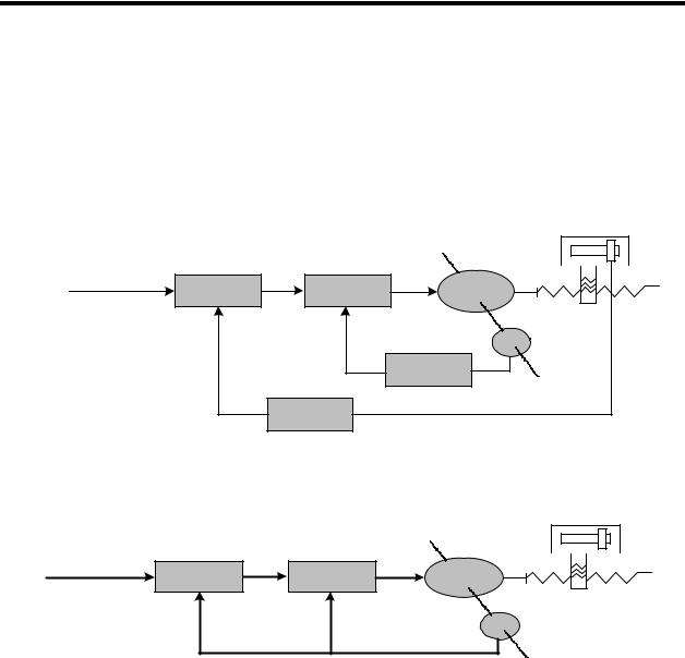
control unit. According to the detection points, the closed-loop control device can be divided into full-closed-loop control and semi-closed-loop control. The former one is to detect the controlled variables directly for feedback (see Fig. 1-4); the mechanical position is controlled variables; the grating ruler mounted on the machine is taken as feedback unit; the encoder on the servo motor serves as speed feedback unit. Thus the full-closed-loop control can be realized. If there is no grating ruler, the encoder serves as both position and speed feedback unit (see Fig. 1-5). Thus, the semi-closed-loop control can be realized.
|
|
|
|
|
Machine |
Specify |
|
|
|
|
|
Command |
Position |
Speed |
Motor |
||
|
|
Comparision |
|
Comparision |
|
|
|
|
|
||
|
|
|
|
|
|
|
|
|
|
|
PG |
|
|
|
|
|
Speed |
|
|
|
|
|
Feedback |
|
|
|
Position |
|
|
|
|
|
Feedback |
|
|
Fig. 1-4 Full-closed-loop control device
Machine
Specify |
|
|
|
Command |
Position |
Speed |
Motor |
|
Comparision |
Comparision |
|
|
|
||
|
|
|
|
PG
Fig. 1-5 Semi-closed-loop control device
z PID control: It is the most commonly used algorithm. “P” is Proportional, representing the linear proportional relationship between input and output of control unit. The larger the value is, the more sensitive the system is, and the smaller the steady-state error will be (impossible to eliminate); however, too large proportional coefficient will lead to system instability. “I” is Integral, representing the accumulation of past errors. Larger integral time constant means the system is more stable till the stead-state error is eliminated; however, it also may lead to lower response of the system. “D” is Differential, representing the prediction of future errors, based on current rate of change. It can decrease the following error and improve the dynamic property. When the integral is too large, the system will be unstable. P, I, D are interacted for the balance among system response, control precision and stability. Since the integral control will easily cause impact and oscillation, PI control (i.e., proportion and integral control) is mainly described in this manual.
¾Concept about servo control
There are three kinds of control mode: position control, speed control and torque control. Shown
3

GS Series Spindle Servo Drive Unit User Manual
in Fig. 1-6:
zPosition control: Specify the rotation direction and angle (position) of the motor in forms of digital pulse or data communication.
zSpeed control: Specify the rotation direction and speed of the motor in forms of analog voltage or data communication.
zTorque control: Specify the magnitude and direction of output torque of the motor in forms of analog voltage or data communication.
The servo drive described in this manual repels the torque control signal, therefore the torque control mode is not provided here.
Fig. 1-6 Three-loop control system
¾Performance norm of spindle servo drive
Dynamic performance: means the response speed, dynamic error and steady-state error of spindle servo drive when the load is specified or changed. The following figure shows the dynamic response of step signal specified by spindle servo drive (the full line represents the specified signal and dashed line represents the output signal; similarly hereinafter).
C(t) |
|
Rmax(t) |
±5%R(t) |
|
|
R(t) |
|
0.9R(t) |
|
t r |
t |
|
t s |
Fig. 1-7 Dynamic response curve
Rise time tr: The duration that the rotation output value rises from 0 to 90% of the steady-state value for the first time. It represents the speed of dynamic response.
4
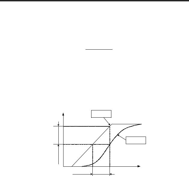
Chapter I Instruction
Settling time ts: The range -5 ~+5% of the steady-state value is taken as permitted error zone. The settling time is the minimum duration of the response curve to reach the zone (no excess any more). It is used to measure the speed of the whole control process.
Percent overshoot σ: It is the maximum fraction by which the response overshoots the steady-state value and expressed as a percentage, i.e.
σ(%) = Rmax (t) − R(t) ×100%
R(t)
Steady-state error: The difference between the steady-state output value to the reference input value at steady state is called the steady state error of the system.
Static performance: Stability is the crucial factor of a spindle servo drive. The static performance mainly refers to positioning accuracy which means the difference between the reference state and actual state after the transient process. The static precision can be affected by measurement device error as well as the system error which is related to the system structure and parameters. Fig. 1-8 shows the static curve of position servo drive.
θ |
Commanded |
Position |
|
|
Following |
|
Response |
Following Error |
|
Lag |
t |
Fig. 1-8 Static curve
Following error: The difference between the required position and actual position is called following error. It equals to commanded position value minus actual position value.
Servo rigidity: The capacity of resisting deviation which is caused by load.
¾Comparison between spindle servo drive and inverter drive
Although both two kinds of devices can realize the conversion of AC-DC-AC, and drive the three-phase asynchronous motor, the spindle servo drive bears larger current frequency range and wider valid regulating range. Since an encoder is mounted on servo motor, the spindle servo drive belongs to closed-loop control device. Whereas, no encoder is mounted on an inverter-fed motor, the inverter drive belongs to open-loop control device. Motor’s rotation speed will change as the load changes; however, since feedback control function is not available, the inverter cannot recover the speed like the servo unit does. To reduce cost, the overload capacity of inverter is 10%~20%, and that of servo unit is greater than 50%. Higher overload capacity means faster acceleration and response.
Compared with inverter drives, the spindle servo drives have the following advantages:
5
GS Series Spindle Servo Drive Unit User Manual
zBoth speed and position control are available; the control precision is high;
zWider regulating range; capable of outputting valid torque in zero-speed state;
zSmall speed fluctuation when load changes; quick to recover;
zStrong overload capacity; fast response; high efficiency; adaptable to sudden start/stop conditions;
1.2Product Confirmation
Check the following items after receiving the products. Please contact us or the supplier if you come across any question.
Item |
Remark |
|
Check the consistency of servo |
Check the nameplate. |
|
unit and servo motor |
||
|
||
Check the completeness of |
Check the contents on packing list and contact |
|
accessories |
the supplier if an inconsistency is found. |
|
Check whether the product is |
Check the overall appearance. |
|
damaged during delivery |
||
|
||
Check whether the screw is |
Check for loose connection with a screwdriver. |
|
loose |
||
|
Caution 1. Spindle servo unit with loss or damage of parts should not be installed.
2.Servo unit should be matched with a servo motor with suitable power.
3.There are two types of GS series products: D-SUB and MDR. Make sure that the used product meets the requirements.
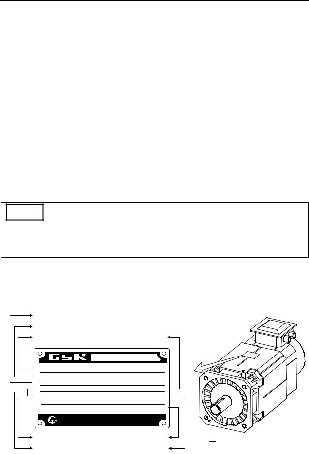
1.2.1Instruction of AC Spindle Servo Motor Model
¾Nameplate of spindle servo motor:
 Flange mounting plane B5
¾Instruction of spindle servo motor model:
6
Chapter I Instruction
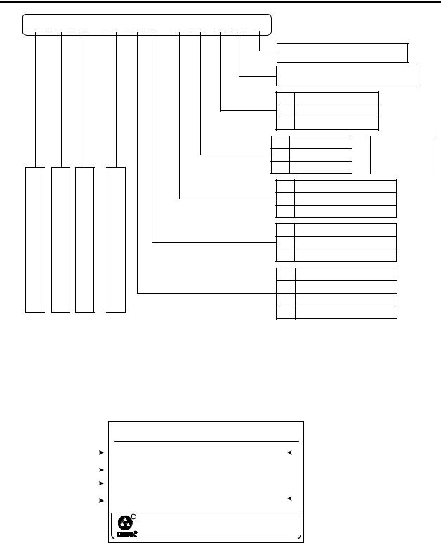
1.2.2 Instruction of Spindle Servo Unit
Example: (nameplate)
|
|
|
|
|
|
Corresponding servo motor model |
|
|
|
|
|
|
|
||||||||||
|
|
|
|
|
|
|
|
|
|
|
|
|
|||||||||||
|
|
|
|
|
|
|
Product model |
|
|
|
|
|
|
|
|
|
|
|
|||||
|
|
|
|
|
|
|
|
|
|
|
|
|
|
|
|
|
|||||||
|
|
|
|
|
|
AC Asynchronous Spindle Servo Unit |
|
|
|||||||||||||||
|
|
|
|
|
|
|
Model:GS3075Y-CP2-7.5 |
|
SVD: V3.04 |
|
|
|
|
|
Software version |
||||||||
|
|
|
|
|
|
|
|
|
|
|
|||||||||||||
|
|
|
|
|
|
|
Servo Motor |
ZJY-208-7.5BH |
|
|
|
|
|
|
|
|
|
||||||
|
|
|
|
|
|
|
|
|
|
|
|
|
|||||||||||
|
|
|
|
|
|
|
Input Power Three-phase 380V(-15% +10%)50/60Hz |
Ex-factory date |
|||||||||||||||
|
|
|
|
||||||||||||||||||||
|
|
|
|
|
|
|
No. |
100620 |
|
EXW. Date |
2010/9 |
|
|
|
|
|
|||||||
|
|
|
|
|
|
|
|
|
|
|
|
|
|||||||||||
|
|
|
|
|
|
|
|
|
|
|
|
|
|||||||||||
|
|
|
|
|
|
|
|
|
|
|
|
|
|
|
|||||||||
|
|
|
|
|
|
|
R |
GSK CNC Equipment Co., Ltd |
|
|
|||||||||||||
|
|
|
|
|
|
|
|
|
|
||||||||||||||
|
|
|
|
|
|
|
|
Tel .020 -83969288 Fax.81997083 |
|
|
|||||||||||||
|
|
|
|
|
|
Product number |
|
|
|
|
|
|
|
|
|
|
|
||||||
|
|
|
|
|
|
|
|
|
|
|
|
|
|
|
|
|
|||||||
|
|
|
|
|
|
|
Input power supply |
|
|
|
|
|
|
|
|
|
|
|
|||||
|
|
|
|
|
|
|
|
|
|
|
|
|
|
|
|
|
|||||||
|
Model instruction: |
|
|
|
|
|
|
|
|
|
|
|
|
|
|
|
|
||||||
|
|
|
|
|
|
|
|
|
|
|
|
|
|
|
|
|
|
|
|
|
|
|
|
|
|
|
|
|
|
|
GS |
|
3 |
|
|
075 |
|
Y |
- |
C |
|
P |
|
|
2 |
|
|
|
|
|
|
|
|
|
|
|
|
|
|
|
|
|
|
|
|
|
|||||
|
|
|
|
|
|
|
|
|
|
|
|
|
|||||||||||
|
GS Series MDR Servo Unit, G: GSK; S: SERVO |
|
|
|
|
|
|
|
|
|
|
|
|||||||||||
|
Voltage grade code, 2: 220V; 3: 380V; 4: 440V. |
|
|
|
|
|
|
|
|
|
|
|
|||||||||||
7

GS Series Spindle Servo Drive Unit User Manual
Nominal current of power component (in three digits): 048, 050, 075, 100, 148, 150 (unit: A)
Motor type: T: synchronous servo motor; Y: asynchronous servo motor.
Communication bus code; N: none; C: GSK-CAN; L: GSK-Link
Feedback (encoder) interface type code; P: incremental encoder; A: Absolute encoder, no backup battery; B: absolute encoder (with backup battery which is used when power-off).
Feedback (encoder) interface configuration code (in 1 digit); 1: The input interface CN2 for motor feedback
(i.e., the 1st position feedback); 2: Input interfaces CN2 and CN3 for motor feedback and the 2nd position feedback.
Position feedback signal interface type and configuration:
|
|
Instruction for feedback (encoder) interface type and configuration |
|
|
|
|
|
P |
1 |
CN2; incremental encoder; |
|
|
|
||
2 |
CN2 and CN3; incremental encoder; |
||
|
|||
|
|
|
|
|
1 |
CN2; incremental encoder or absolute encoder (compatible with Biss and TAMAGAWA |
|
A |
communication protocols; automatic identification); |
||
|
|||
B |
2 |
CN2 and CN3; incremental encoder or absolute encoder (compatible with Biss and |
|
|
TAMAGAWA communication protocols; automatic identification); |
||
|
|
||
|
|
|
1.2.3 Overall Appearance of Spindle Servo Unit
According to different signal interfaces, the GS Series Spindle Servo Unit can be divided into D-SUB type and MDR type. The products that adopt D-SUB interfaces provided by WIESON Company belong to D-SUB type. They are matched with incremental encoder and not equipped with GSK-CAN. The products that adopt MDR interfaces provided by 3M Company belong to MDR type. They are compatible with absolute encoder and equipped with GSK-CAN bus.
8

Chapter I Instruction
zOverall Appearance of GS Series AC Spindle Servo Unit (D-SUB Type)
The figure below shows the structure of following products: GS3048Y-N Series, GS3050Y-N Series, GS3075Y-N Series GS3100Y-N Series, GS3148Y-N Series, GS4048Y-N Series, GS4050Y-N Series, GS4075Y-N Series, GS4100Y-N Series, GS4148Y-N Series.
Increase parameter number
and value. Decrease parameter
number and value.
Move to the digit to be edited.
Return to the previous menu or cancel the last operation.
Enter to a sub-menu or confirm the operation
Indicator |
‘CHARGE” is the indicator of DC |
|
bus voltage in the main circuit. |
||
|
||
|
ON: normal |
|
|
OFF: the bus is discharged |
|
|
When ‘CHARGE' indicator comes |
|
|
ON, connecting or disconnecting the |
|
|
servo unit line, power supply line, motor |
|
|
line or braking resistor line is forbidden. |
Terminal block of main circuit
Connection should be done
!according to contents in Section 3.2.2 with suitable terminals, and tighten the screw afterwards.
input power ground; GND of motor protective ground
R |
|
|
|
AC |
|
|
Serie |
Servo |
Mot or |
Driv es Unit |
CHARGE
POWER
C N 3
C N 2
C N 1
LED monitoring window
Monitor the running status or parameter modification and management.
Indicator |
‘POWER’ is the indicator of |
|
power supply of control circuit. |
||
|
||
|
ON: normal |
|
|
OFF: power failure |
CN1: Control signal interface
(44-pole DB female)
For external speed command signal, position command signal and output signal
CN2: encoder feedback input interface
(25-pole DB female)
For incremental encoder differential signal, motor position feedback input
CN3: 2nd position encoder feedback input interface (9-pole DB female)
For incremental encoder differential signal, spindle encoder position feedback input
Open
R |
380V |
|
S |
||
T |
|
|
P |
BRAKE |
|
B |
||
|
||
U |
MOTOR |
|
V |
||
W |
|
|
r |
380V |
|
t |
Terminal block of main circuit
!Check the nameplate before connection; make sure that the input power voltages R, S, T, r, t are correct. Connect to U, V, W as market at the terminal end; if Err-27 occurs, exchange any of the two phases.
Fig. 1-9 (a) Overall appearance of GS Series AC spindle servo unit (D-SUB type)
9

GS Series Spindle Servo Drive Unit User Manual
The figure below shows the structure of following D-SUB products: GS3150Y-N Series, GS4150Y-N Series.
Fig. 1-9 (b) Overall appearance of GS Series AC spindle servo unit (D-SUB type)
zOverall Appearance of GS Series AC Spindle Servo Unit (MDR Type)
The figure below shows the structure of following products: GS3048Y-C Series, GS3050Y-C Series, GS3075Y-C Series, GS3100Y-C Series, GS3148Y-C Series, GS4048Y-C Series, GS4050Y-C Series, GS4075Y-C Series, GS4100Y-C Series, GS4148Y-C Series.
Backup battery
(See the instruction of servo unit model)
Increase parameter number
and value. Decrease parameter
number and value.
Move to the digit to be edited.
Return to the previous menu or cancel the last operation.
Enter to a sub-menu or confirm the operation
Indicator |
‘CHARGE” is the indicator of DC |
|
bus voltage in the main circuit. |
||
|
||
|
ON: normal |
|
|
OFF: the bus is discharged |
|
|
When ‘CHARGE' indicator comes |
|
|
ON, connecting or disconnecting the |
|
|
servo unit line, power supply line, motor |
|
|
line or braking resistor line is forbidden. |
|
|
Terminal block of main circuit |
|
|
Connection should be done |
|
! |
according to contents in Section 3.2.2 |
|
with suitable terminals, and tighten |
||
|
the screw afterwards. |
R |
|
|
|
|
A C |
Serv o |
|
r |
Series |
Moto |
Driv e Unit |
CHARGE |
POWER |
C N 3
C N 2
C N 1
C N 4
C N 5
LED monitoring window
Monitor the running status or parameter modification and management.
Indicator |
‘POWER’ is the indicator of power |
|
supply of control circuit. |
||
|
||
|
ON: normal |
|
|
OFF: power failure |
CN1: control signal interface (50-pin high-density )
For external speed command signal, position command signal, input/output signal.
CN2: encoder feedback input interface (26-pin high-density)
For incremental or absolute encoder feedback input signal
CN3: 2nd position encoder feedback
input interface (20-pin high-density)
For spindle encoder position feedback input, incremental or absolute input signal.
input power ground; GND |
CN4, CN5: GSK-CAN |
|
communication interface |
||
of motor protective ground |
||
Realize servo unit commissioning and |
||
|
||
|
real-time monitoring. |
Fig. 1-10 (a) Overall appearance of GS Series AC spindle servo unit (MDR type)
10
Chapter I Instruction
The figure below shows the structure of following products: GS3150Y-C Series, GS4150Y-C Series.
LED monitoring window
Monitor the running status or parameter modification and management.
Indicator |
‘CHARGE” is the indicator of DC |
|
bus voltage in the main circuit. |
||
|
||
|
ON: normal |
|
|
OFF: the bus is discharged |
|
|
When ‘CHARGE' indicator comes |
|
|
ON, connecting or disconnecting the |
|
|
servo unit line, power supply line, motor |
|
|
line or braking resistor line is forbidden. |
|
|
Terminal block of main circuit |
|
|
Connection should be done |
|
! |
according to contents in Section 3.2.2 |
|
with suitable terminals, and tighten |
||
|
the screw afterwards. |
|
|
input power ground; GND |
|
|
of motor protective ground |
Terminal block of control power line
Check the nameplate before
!connection; make sure the r,t power voltages are correct.
R |
|
|
|
AC Servo |
|
Series |
|
Motor Drive |
Unit |
||
|
CHARGE |
POWER |
R |
380V |
C |
|
N |
|
S |
|
3 |
|
|
|
T |
|
|
|
|
C |
P |
|
N |
BRAKE |
2 |
|
B |
|
|
|
|
|
U |
|
|
|
MOTOR |
C |
V |
N |
|
|
1 |
|
W |
|
|
|
|
C |
|
|
N |
|
|
4 |
|
|
C |
|
|
N |
|
|
5 |
r |
380V |
|
t |
|
Increase parameter number and value.
Decrease parameter number and value.
Move to the digit to be edited.
Return to the previous menu or
cancel the last operation. Enter to a sub-menu or
confirm the operation
Indicator |
‘POWER’ is the indicator of power |
|
supply of control circuit. |
||
|
||
|
ON: normal |
|
|
OFF: power failure |
CN1: control signal interface (50pin high-density )
For external speed command signal, position command signal, input/output signal.
CN2: encoder feedback input interface (26-pin high-density)
For incremental or absolute encoder feedback input signal
CN3: 2nd position encoder feedback
input interface (20-pin high-density)
For spindle encoder position feedback
input, incremental or absolute input signal.
CN4, CN5: GSK-CAN communication interface
Realize servo unit commissioning and real-time monitoring.
Fig. 1-10 (b) Overall appearance of GS Series AC spindle servo unit (MDR type)
1.3 Technical Specification
1.3.1 Technical Specification of Spindle Motor
SPEC |
ZJY208 |
ZJY208 |
ZJY208 |
ZJY265 |
ZJY265 |
ZJY265 |
ZJY182 |
ZJY182 |
|
Item |
-2.2AM |
-3.7AM |
-5.5AM |
-7.5AM |
-11AM |
-15AM |
-1.5BH |
-2.2BH |
|
Rated power |
2.2 |
3.7 |
5.5 |
7.5 |
11 |
15 |
1.5 |
2.2 |
|
(kW) |
|||||||||
|
|
|
|
|
|
|
|
Servo Unit |
|
|
Three-phase AC 380V 50 Hz /60Hz |
|
|
|
||||
Power Supply |
|
|
|
|
|
|||||
|
|
|
|
|
|
|
|
|
|
|
Rated Current |
6.7 |
10.2 |
15.5 |
|
21 |
31 |
48.3 |
7.3 |
|
7.5 |
(A) |
|
|
|
|
|
|
|
|||
|
|
|
|
|
|
|
|
|
|
|
Rated |
33.3 |
33.3 |
33.3 |
|
33.3 |
33.3 |
33.3 |
50 |
|
50 |
Frequency(Hz) |
|
|
||||||||
|
|
|
|
|
|
|
|
|
|
|
Rated |
21 |
35 |
53 |
|
72 |
105 |
143 |
9.5 |
|
14 |
Torque(N·m) |
|
|
|
|
|
|
|
|||
|
|
|
|
|
|
|
|
|
|
|
30min Power |
3.7 |
5.5 |
7.5 |
|
11 |
15 |
18.5 |
2.2 |
|
3.7 |
(kW) |
|
|
|
|
|
|
|
|
|
|
30min Current |
9.8 |
13.8 |
19.6 |
|
28 |
39 |
56 |
9.3 |
|
11 |
(A) |
|
|
|
|
|
|
|
|||
|
|
|
|
|
|
|
|
|
|
|
30min Torque |
35 |
53 |
72 |
|
105 |
143 |
177 |
14 |
|
24 |
(N·m) |
|
|
|
|
|
|
|
|||
|
|
|
|
|
|
|
|
|
|
|
Rated Speed |
1000 |
1000 |
1000 |
1000 |
1000 |
1000 |
1500 |
1500 |
||
(r/min) |
|
|
|
|
|
|||||
|
|
|
|
|
|
|
|
|
|
|
Constant Power |
|
|
1000 4000 |
|
|
|
|
|
||
Range |
|
|
|
|
|
|
|
|||
|
|
|
|
|
|
|
|
|
|
|
Max. Speed |
|
|
|
M:7000 |
|
|
|
H:10000 |
||
11

GS Series Spindle Servo Drive Unit User Manual
SPEC |
ZJY208 |
ZJY208 |
ZJY208 |
ZJY265 |
ZJY265 |
ZJY265 |
ZJY182 |
ZJY182 |
Item |
-2.2AM |
-3.7AM |
-5.5AM |
-7.5AM |
-11AM |
-15AM |
-1.5BH |
-2.2BH |
Rotary Inertia |
0.0168 |
0.0238 |
0.0309 |
0.0413 |
0.0826 |
0.086 |
0.0056 |
0.0074 |
Weight (kg) |
51 |
66 |
77 |
51 |
125 |
143 |
27 |
32 |
Installation |
|
|
IM B5 or B3 |
|
|
IM B35 |
||
Power Supply of |
Three-phase AC 380V 50Hz 40W |
Three-phase AC 380V 50Hz 70W |
Three-phase AC 380V |
|||||
Cooling Fan |
|
0.14A |
|
|
0.21A |
|
50Hz 30W 0.08A |
|
SPEC |
ZJY182-3.7BH |
ZJY208-3.7 ZJY208-5.5 ZJY208-7.5 |
ZJY265-7.5B |
ZJY265-11B ZJY265-15B |
||||
Item |
|
B |
B |
B |
M |
M |
M |
|
Rated Power |
3.7 |
3.7 |
5.5 |
7.5 |
7.5 |
11 |
15 |
|
(kW) |
||||||||
|
|
|
|
|
|
|
||
Servo Unit |
|
|
|
|
|
|
|
|
|
|
|
Power |
|
|
|
Three-phase AC 380V |
50 Hz /60Hz |
|
|
|
|
||
Supply |
|
|
|
|
|
|
|
|
|
|
|
Rated |
15.5 |
8.9 |
|
13.7 |
18.4 |
18 |
|
|
26 |
|
35 |
Current (A) |
|
|
|
|
|
||||||
|
|
|
|
|
|
|
|
|
|
|
|
Rated |
|
|
|
|
|
|
|
|
|
|
|
Frequency |
50 |
50 |
|
50 |
50 |
50 |
|
|
50 |
|
50 |
(Hz) |
|
|
|
|
|
|
|
|
|
|
|
Rated |
24 |
|
|
|
|
|
|
|
|
|
|
Torque |
|
24 |
|
35 |
48 |
49 |
|
|
72 |
|
98 |
(N·m) |
|
|
|
|
|
|
|
|
|
|
|
30min Power |
5.5 |
5.5 |
|
7.5 |
11 |
11 |
|
|
15 |
|
18.5 |
(kW) |
|
|
|
|
|
|
|
|
|
|
|
30min |
19.6 |
13 |
|
18 |
25 |
26 |
|
|
34 |
|
42 |
Current (A) |
|
|
|
|
|
||||||
|
|
|
|
|
|
|
|
|
|
|
|
30min |
35 |
|
|
|
|
|
|
|
|
|
|
Torque |
|
35 |
|
48 |
70 |
74 |
|
|
100 |
|
123 |
(N·m) |
|
|
|
|
|
|
|
|
|
|
|
Rated Speed |
1500 |
1500 |
|
1500 |
1500 |
1500 |
|
1500 |
|
1500 |
|
(r/min) |
|
|
|
|
|||||||
|
|
|
|
|
|
|
|
|
|
|
|
Constant |
|
|
|
|
|
|
|
|
|
|
|
Power |
|
|
|
|
1500 5000 |
|
|
|
|
|
|
Range |
|
|
|
|
|
|
|
|
|
|
|
Max. Speed |
H:10000 |
|
M:7000, H:10000 |
|
|
|
M:7000 |
|
|||
Rotary |
0.0115 |
0.0168 |
|
0.0238 |
0.0309 |
0.0413 |
|
0.0744 |
|
0.0826 |
|
Inertia |
|
|
|
||||||||
|
|
|
|
|
|
|
|
|
|
|
|
Weight (kg) |
43 |
51 |
|
66 |
77 |
89 |
|
|
107 |
|
125 |
Installation |
IM B35 |
|
|
|
IM B5 or B3 |
|
|
|
|
||
Power |
Three-phase |
|
|
|
|
|
|
|
|
|
|
AC 380V |
|
|
|
|
|
|
Three-phase AC 380V 50Hz |
||||
Supply of |
Three-phase AC 380V 50Hz 40W 0.14A |
|
|||||||||
50Hz 30W |
|
|
70W 0.21A |
|
|||||||
Cooling Fan |
|
|
|
|
|
|
|
|
|||
0.08A |
|
|
|
|
|
|
|
|
|
|
|
|
|
|
|
|
|
|
|
|
|
|
|
Protection |
|
|
|
IP54 GB/T 4942.1—2006 |
|
|
|
|
|||
Level |
|
|
|
|
|
|
|
||||
|
|
|
|
|
|
|
|
|
|
|
|
Insulation |
|
|
|
F GB 755—2008 |
|
|
|
|
|||
Level |
|
|
|
|
|
|
|
|
|
|
|
Vibration |
|
|
|
R GB 10068—2008 |
|
|
|
|
|||
Level |
|
|
|
|
|
|
|
|
|
|
|
Internal |
|
|
|
Incremental encoder1024 p/r |
|
|
|
|
|||
Encoder |
|
|
|
|
|
|
|
||||
|
|
|
|
|
|
|
|
|
|
|
|
12

Chapter I Instruction
Mechanical Characteristics of Motor
P/PN: Power/Rated power; T/TN: Torque/Rated torque; n: Rotation speed of spindle servo motor;
ZJY182 rated rotation speed: 1500r/min |
ZJY208 rated rotation speed: 1500r/min |
||||||||
|
|
|
|
|
|
|
|
|
|
|
|
|
|
|
|
|
|
|
|
|
|
|
|
|
|
|
|
|
|
|
|
|
|
|
|
|
|
|
|
|
|
|
|
|
|
|
|
|
|
|
|
|
|
|
|
|
|
|
|
|
|
|
|
|
|
|
|
|
|
|
|
|
|
|
|
|
|
|
|
|
|
|
|
|
|
|
|
|
|
|
|
|
|
|
|
|
|
|
|
ZJY265 rated rotation speed: 1500r/min |
ZJY208, ZJY265 rated rotation speed: 1500r/min |
||||
|
|
Power in continuous working status; |
|
Power in 30min’s working status; |
|
|
|
|
|||
|
|
Torque in continuous working status; |
Torque in 30min’s working status |
||
1.3.2 Technical Specification of AC Spindle Servo Unit
Model |
GS3048Y |
GS3050Y |
GS3075Y |
GS3100Y |
GS3148Y |
GS3150Y |
|
GS4048Y |
GS4050Y |
GS4075Y |
GS4100Y |
GS4148Y |
GS4150Y |
||
|
|||||||
Rated Power (kW) |
1.5, 2.2 |
3.7, 5.5 |
5.5, 7.5 |
7.5, 11 |
11 |
15, 18.5 |
|
Input Power |
Input power of GS3□□□Y Series is: Three-phase AC380V 0.85 1.1 , 50/60Hz±1Hz |
||||||
Input power of GS4□□□Y Series is: Three-phase AC440V 0.85% 1.1 , 50/60Hz±1Hz |
|||||||
|
|||||||
Dimension (mm) |
112×230×1 |
120×270×218 |
130×305×248.5 |
160×305×273.5 |
160×370×273.5 |
||
(width×height×depth) |
82 |
|
|
|
|
|
|
Regulating Range |
|
|
1 10000 |
|
|
||
(r/min) |
|
|
|
|
|||
|
|
|
|
|
|
||
Speed Fluctuation |
|
|
Rated Speed ×0.1% |
|
|
||
Rate |
|
|
|
|
|||
|
|
|
|
|
|
||
Working Mode |
|
MANUAL, JOG, SPEED, POSITION, SPEED/POSITION |
|
||||
13
|
|
GS Series Spindle Servo Drive Unit |
User Manual |
|
|
|
|
|
|
|
|
|
Internal Speed Mode |
Motor rotates at the speeds set by internal parameters (speed closed-loop control)\ |
|
|
Running speed is selected by input signal. |
|
|
|
|
|
|
|
External Speed Mode |
Motor rotates at the speed specified by external analog voltage (speed closed-loop control) |
|
|
|
|
|
|
External Speed |
10V +10V or 0V +10V, selected by parameters |
|
|
Command Mode |
|
|
|
|
|
|
|
Speed Command |
Speed command frequency multiplication; frequency division coefficient:1~100 |
|
|
Electronic Gear |
||
|
|
|
|
|
Position Mode |
Motor rotates by position pulse command (position closed-loop control); the direction and |
|
|
quantity of pulse command determine the rotation direction and angle; the pulse frequency |
||
|
|
determines the rotation speed. |
|
|
Position Command |
Pulse/direction; CCW pulse/CW pulse; A/B two-phase orthogonal pulse; max. pulse |
|
|
Pulse Mode |
frequency: 1MHz |
|
|
Position Command |
Command pulse frequency multiplication coefficient: 1 32767; Command pulse frequency |
|
|
Electronic Gear |
division coefficient: 1 32767 |
|
|
Positioning Accuracy |
±0.088° (matched with incremental encoder with 1024 lines) |
|
|
|
|
|
|
Orientation |
4-point orientation; 4 orientation angle is set by parameters; orientation position is selected |
|
|
through input signal; orientation error is ±180°/C (C is the line number of position feedback |
||
|
|
encoder) |
|
|
Motor Feedback Input |
GS3□□□Y-NP2 and GS4□□□Y-NP2 D-SUB type: adopt incremental encoder; |
|
|
GS3□□□Y-C□2 and GS4□□□Y-C□2 MDR type: adopt incremental encoder or absolute |
||
|
|
encoder (compatible with two communication protocols: Biss and TAMAGAWA). |
|
|
2nd Position Feedback |
GS3□□□Y-NP2 D-SUB type: adopt incremental encoder; |
|
|
GS3□□□Y-C□2 MDR type: adopt incremental encoder or absolute encoder (compatible with |
||
|
Input |
two communication protocols: Biss and TAMAGAWA). |
|
|
(optional) |
|
|
|
|
|
|
|
|
GS3□□□Y-NP2 D-SUB type: motor feedback input signal or 2nd position feedback input |
|
|
|
signal output in 1:1; |
|
|
Position Feedback |
GS3□□□Y-C□2 MDR type : motor feedback input signal or 2nd position feedback input |
|
|
Output |
signal output in frequency division; the range of numerator and dominator in position |
|
|
|
feedback output gear ratio is 1 32767, and the dominator should be larger than or equal to |
|
|
|
numerator; |
|
|
Communication Bus |
GS3□□□Y-NP2 and GS4□□□Y-NP2 D-SUB type : no communication bus; |
|
|
GS3□□□Y-C□2 and GS4□□□Y-C□2 MDR type : GSK-CAN |
||
|
|
||
|
Input Signal |
Servo enable; CCW start; CW start; orientation/speed selection; orientation start; 2nd speed |
|
|
gain selection; spindle clamping interlock signal; zero-speed clamping; alarm clear; |
||
|
|
speed/position switching |
|
|
Output Signal |
Servo ready; zero speed output; position/speed arrival; orientation completed; alarm output |
|
|
speed/position status; encoder zero point; |
|
|
|
|
|
|
|
Function Protection |
Undervoltage protection; overvoltage protection; servo unit overcurrent protection; servo |
|
|
motor thermal overload protection; overspeed protection; overshoot protection; brake |
||
|
|
abnormality protection; encoder abnormality protection; motor overheat protection. |
|
|
Operation and Display |
5 keys for manual, JOG operation and parameter modification, setting, writing and backup; |
|
|
6-digit LED displays rotation speed, current position, command pulse accumulation, position |
||
|
|
deviation, motor torque, motor current, absolute position of rotator, I/O signal status etc. |
|
|
Braking Resistor |
Externally connected (no internal braking resistor) |
|
|
|
|
|
Note: CCW means the motor rotates in counter clockwise direction (viewing from the shaft extension side). CW means the motor rotates in clockwise direction (viewing from the shaft extension side).
14
Chapter I Instruction
1.4 Ordering Guidelines
1.4.1 Model Selection Process
Rated rotation speed is 1000r/min (recommended in turning machine
Rated rotation speed is 1500r/min (recommended in milling machine)
1. Flange mounting or foot mounting;
2. With or without a keyway;
Pay attention to the difference between economical type and universal type
Select motor |
1.5 2.2 3.7 5.5 |
|
7.5 11 15 18.5 are |
||
power |
||
optional Unit: kW |
||
|
||
Select the rated |
|
|
rotation speed |
|
|
Select the max. |
1. Low: 4500r/min |
|
2: Medium:7000r/min |
||
rotation speed |
||
3. High: 10000r/min; |
||
|
Select the mounting method
Select the
encoder
Select the motor model
Select the servo unit model
After selecting the motor model, you can select the servo unit model according to the relationship described in 1.4.2.
1.4.2 Examples
1. The model of GS Series servo device (including ZJY Series spindle servo motor) is shown as follows:
GS servo unit model — ZJY spindle servo motor model
Example: GS3075Y-NP2—ZJY208-7.5BM -B5LY1
Instruction: the model of spindle servo unit is GS3075Y-NP2, and the corresponding model of spindle servo motor is ZJY208-7.5BM -B5ALY1. The accessories are the standard ones (see Section 1.4.3).
2. The model of GS Series servo device (not including ZJY Series spindle servo motor) is shown as follows:
GS servo unit model — Servo motor model
Example: GS3075Y-NP2— ZJY208-7.5BM -B5LY1
Instruction: the model of spindle servo unit is GS3075Y-NP2, and the ex-factory parameters should be set according to the model in the brackets. The accessories are the standard ones (see Section 1.4.3).
15

GS Series Spindle Servo Drive Unit User Manual
Model list of GS Series servo unit and ZJY Series servo motor:
Servo Unit |
|
|
Major Parameters of Spindle Motor |
||||
Motor Model |
|
|
|
|
|
||
Rated |
Rated |
|
Rated |
|
|||
Model |
|
|
|||||
|
Max. Speed |
Standard Encoder |
|||||
|
|
|
|
||||
|
|
Power |
Speed |
Current |
|||
|
|
|
|
||||
|
|
|
|
|
|
1024-line |
|
|
ZJY182-1.5BH |
1.5kW |
1500 rpm |
10000rpm |
7.3 A |
incremental |
|
|
|
|
|
|
|
encoder |
|
|
|
|
|
|
|
1024-line |
|
GS3048Y-NP2 |
ZJY182-2.2BH |
2.2kW |
1500 rpm |
10000rpm |
7.5 A |
incremental |
|
GS3048Y-CP2 |
|
|
|
|
|
encoder |
|
GS4048Y-NP2 |
|
|
|
|
|
1024-line |
|
GS4048Y-CP2 |
ZJY208-2.2AM |
2.2kW |
1000rpm |
7000rpm |
6.7A |
incremental |
|
|
|
|
|
|
|
encoder |
|
|
|
|
|
|
|
1024-line |
|
|
ZJY208-2.2BM |
2.2kW |
1500rpm |
7000rpm |
9.3A |
incremental |
|
|
|
|
|
|
|
encoder |
|
|
|
|
|
7000rpm |
|
1024-line |
|
|
ZJY182-3.7BH |
3.7kW |
1500 rpm |
15.5 A |
incremental |
||
|
10000rpm |
||||||
|
|
|
|
|
encoder |
||
|
|
|
|
|
|
||
|
|
|
|
|
|
1024-line |
|
GS3050Y-NP2 |
ZJY208-3.7AM |
3.7kW |
1000rpm |
7000rpm |
10.2A |
incremental |
|
GS3050Y-CP2 |
|
|
|
|
|
encoder |
|
GS4050Y-NP2 |
ZJY208-3.7BM |
|
|
7000rpm |
|
1024-line |
|
GS4050Y-CP2 |
3.7kW |
1500rpm |
8.9A |
incremental |
|||
ZJY208-3.7BH |
10000rpm |
||||||
|
|
|
|
encoder |
|||
|
|
|
|
|
|
||
|
ZJY208-5.5BM |
|
|
7000rpm |
|
1024-line |
|
|
5.5kW |
1500rpm |
13.7A |
incremental |
|||
|
ZJY208-5.5BH |
10000rpm |
|||||
|
|
|
|
encoder |
|||
|
|
|
|
|
|
||
|
|
|
|
|
|
1024-line |
|
|
ZJY208-5.5AM |
5.5kW |
1000rpm |
7000rpm |
15.5A |
incremental |
|
GS3075Y-NP2 |
|
|
|
|
|
encoder |
|
|
|
|
|
|
1024-line |
||
GS3075Y-CP2 |
ZJY208-7.5BM |
|
|
7000rpm |
|
||
7.5kW |
1500rpm |
18.4A |
incremental |
||||
GS4075Y-NP2 |
ZJY208-7.5BH |
10000rpm |
|||||
|
|
|
encoder |
||||
GS4075Y-CP2 |
|
|
|
|
|
||
|
|
|
|
|
1024-line |
||
|
|
|
|
|
|
||
|
ZJY265-7.5BM |
7.5kW |
1500rpm |
7000rpm |
18A |
incremental |
|
|
|
|
|
|
|
encoder |
|
16

Chapter I Instruction
Servo Unit |
|
|
Major Parameters of Spindle Motor |
||||
Motor Model |
|
|
|
|
|
||
Rated |
Rated |
|
Rated |
|
|||
Model |
|
|
|||||
|
Max. Speed |
Standard Encoder |
|||||
|
|
|
|
||||
|
|
Power |
Speed |
Current |
|||
|
|
|
|
||||
|
|
|
|
|
|
1024-line |
|
GS3100Y-NP2 |
ZJY265-7.5AM |
7.5kW |
1000rpm |
7000rpm |
21A |
incremental |
|
GS3100Y-CP2 |
|
|
|
|
|
encoder |
|
GS4100Y-NP2 |
|
|
|
|
|
1024-line |
|
GS4100Y-CP2 |
ZJY265-11BM |
11kW |
1500rpm |
7000rpm |
26A |
incremental |
|
|
|
|
|
|
|
encoder |
|
GS3148Y-NP2 |
|
|
|
|
|
1024-line |
|
GS3148Y-CP2 |
|
|
|
|
|
||
ZJY265-11AM |
11kW |
1000rpm |
7000rpm |
31A |
incremental |
||
GS4148Y-NP2 |
|||||||
|
|
|
|
|
encoder |
||
GS4148Y-CP2 |
|
|
|
|
|
||
|
|
|
|
|
|
||
|
|
|
|
|
|
1024-line |
|
|
ZJY265-15AM |
15kW |
1000rpm |
7000rpm |
48.3A |
incremental |
|
GS3150Y-NP2 |
|
|
|
|
|
encoder |
|
|
|
|
|
|
1024-line |
||
GS3150Y-CP2 |
|
|
|
|
|
||
ZJY265-15BM |
15kW |
1500rpm |
7000rpm |
35A |
incremental |
||
GS4150Y-NP2 |
|||||||
|
|
|
|
|
encoder |
||
GS4150Y-CP2 |
|
|
|
|
|
||
|
|
|
|
|
1024-line |
||
|
|
|
|
|
|
||
|
ZJY265-18.5BM |
18.5kW |
1500rpm |
7000rpm |
48.7A |
incremental |
|
|
|
|
|
|
|
encoder |
|
1.4.3 Standard Ex-factory Accessories
The standard ex-factory accessories are listed in the table below. If additional accessories are needed otherwise, please contact our sales office or technical personnels.
zGS Series MDR product accessories list
Type |
Name |
Model |
Number |
Explanation |
Remark |
|
DB-44 male plug and plastic |
|
1 |
CN1 connecting plug |
|
|
case |
|
|
|
|
Servo unit |
|
|
|
|
|
DB-25 male plug and plastic |
|
1 |
CN2 connecting plug |
|
|
(separate |
case |
|
|
|
|
order |
|
|
|
|
|
DB-9 male plug and plastic case |
|
1 |
CN3 connecting plug |
|
|
-no spindle |
|
|
|||
Aluminum-shell braking resistor |
|
|
Including 1m connecting |
|
|
servo |
|
|
|
||
|
|
|
line (refer to Appendix C |
|
|
motor) |
|
|
|
|
|
|
|
|
for the specification and |
|
|
|
|
|
|
|
|
|
|
|
|
quantity) |
|
17

|
|
GS Series Spindle Servo Drive Unit |
User Manual |
|||||
|
|
|
|
|
|
|
|
|
|
|
|
|
|
|
|
|
|
|
Type |
Name |
Model |
Number |
Explanation |
|
Remark |
|
|
|
GS Series Spindle Servo Unit |
|
1 |
Technical materials |
|
|
|
|
|
Manual |
|
|
|
|
|
|
|
|
DB-44 male plug and plastic |
|
1 |
CN1 connecting plug |
|
|
|
|
|
case |
|
|
|
|
|
|
|
|
|
|
|
|
|
|
|
|
|
DB-9 male plug and plastic case |
|
1 |
CN3 connecting plug |
|
|
|
|
|
Motor encoder line |
-00-761A |
1 |
Standard length: 3m |
|
Matched |
|
|
Servo unit |
Motor encoder line |
-00-765* |
1 |
Standard length: 3m |
|
with ZJY |
|
|
and spindle |
Motor fan line |
-00-768A |
1 |
Standard length: 3m |
|
Series |
|
|
servo |
Aluminum-shell braking resistor |
|
|
Including 1m connecting |
|
spindle |
|
|
motor |
|
|
|
line (refer to Appendix C |
|
servo motor |
|
|
|
|
|
|
|
|
||
|
|
|
|
|
for the specification and |
|
|
|
|
|
|
|
|
quantity) |
|
|
|
|
|
GS Series Spindle Servo Unit |
|
1 |
Technical materials |
|
|
|
|
|
Manual |
|
|
|
|
|
|
|
Servo unit |
DB-25 male plug and plastic |
|
1 |
CN2 connecting plug |
|
CN1-CNC |
|
|
case |
|
|
|
|
|||
|
|
|
|
|
|
|||
|
|
|
|
|
signal |
|
||
|
(without |
|
|
|
|
|
|
|
|
DB-9 male plug and plastic case |
|
1 |
CN3 connecting plug |
|
|
||
|
|
|
|
|
||||
|
spindle |
|
|
connecting |
|
|||
|
Aluminum-shell braking resistor |
|
|
Including 1m connecting |
|
|
||
|
servo |
|
|
|
cable is |
|
||
|
|
|
|
line (refer to Appendix C |
|
|
||
|
motor) and |
|
|
|
|
provided |
|
|
|
|
|
|
for the specification and |
|
|
||
|
CNC |
|
|
|
|
together |
|
|
|
|
|
|
quantity) |
|
|
||
|
system |
|
|
|
|
|
||
|
|
|
|
|
|
|
||
|
GS Series Spindle Servo Unit |
|
|
Technical materials |
|
with CNC |
|
|
|
|
|
|
|
|
|||
|
|
|
1 |
|
|
|
||
|
|
Manual |
|
|
|
system |
|
|
|
|
|
|
|
|
|
||
|
|
DB-9 male plug and plastic case |
|
1 |
CN3 connecting plug |
|
|
|
|
|
Motor encoder line |
-00-761A |
1 |
Standard length: 3m |
|
CN1-CNC |
|
|
|
|
|
|
||||
|
Servo unit, |
Motor power line |
-00-765* |
1 |
Standard length: 3m |
|
signal |
|
|
|
|
|
|||||
|
spindle |
Motor fan line |
-00-768A |
1 |
Standard length: 3m |
|
connecting |
|
|
servo |
Aluminum-shell braking resistor |
|
|
Including 1m connecting |
|
cable is |
|
|
motor and |
|
|
|
line (refer to Appendix C |
|
provided |
|
|
CNC |
|
|
|
for the specification and |
|
together |
|
|
system |
|
|
|
quantity) |
|
with CNC |
|
|
|
GS Series Spindle Servo Unit |
|
1 |
Technical materials |
|
|
|
|
|
|
|
system |
|
|||
|
|
Manual |
|
|
|
|
|
|
|
|
|
|
|
|
|
|
|
Note 1: A fan with 440V power should be selected to match with GS4000 Series spindle motor.
zGS Series MDR product accessories list
Type |
Name |
Model |
Number |
Explanation |
Remark |
Servo unit, |
MDR20 (20pin) plug and plastic case |
|
1 |
CN3 connecting plug |
Servo signal |
servo |
Motor encoder line |
-00-761A |
1 |
Standard length: 3m |
line, |
18

Chapter I Instruction
motor and |
Motor power line |
-00-765* |
1 |
Standard length: 3m; “*” |
GSK-CNC |
CNC |
|
|
|
indicates the suffix letters |
communicati |
system |
|
|
|
(see the Motor Power Line |
on line and |
|
|
|
|
Specification) |
terminal plug |
|
Aluminum-shell braking resistor |
|
|
Including 1m connecting |
are provided |
|
|
|
|
line; see Appendix C for |
together with |
|
|
|
|
specification and quantity |
CNC system |
|
GS Series Spindle Servo Unit Manual |
|
1 |
Technical materials |
|
Note 2: So far, GSK-CAN serial bus is supported in GSK988T. GS300Y-CP2 Series MDR spindle servo unit is applicable.
 1. Make clear the model, quantity of products to be ordered (servo unit, servo motor, isolation transformer and CNC). When you need an exclusive software/hardware version or optional accessories, write it on the order sheet.
2.Make clear the type, specification, quantity of non-standard accessories (such as special cable or cable length, or special cable processing).
3.Make clear the code of shaft-extension, structure or leading-out pattern of servo motor. Write special items on the order sheet.
4.When only servo unit (without servo motor) is ordered, write the model of servo model behind the servo unit mode (for example: GS3050T-NP2 ZJY182-3.7BH ). So that relevant parameters can be set before delivery.
5.The spindle servo unit and servo motor with 3-phase AC440V input power are out of stock. They are produced according to the order.
19

GS Series Spindle Servo Drive Unit User Manual
20
 Loading...