


 In this manual, we have tried as much as possible to describe all the various matters about the system. However, we can not describe
all the matters which must not be done or which can not be done
because there are so many possibilities. Therefore, matters which are
not especially described in this manual should be regarded as
“impossible” or “forbidden”.
 The copyright of the user manual is owned by GSK CNC Equipment Co., Ltd (Hereinafter referred to as GSK).It is against the
law for any organization or individual to reproduce this manual in any
form without the permission of GSK and GSK reserves the right to
investigate its law duty.
PREFACE
Dear user:
It’s our great pleasure that you select GSK928GA/GE surface/cylindrical grinding machine CNC system (hereinafter referred to as system).
This manual is divided as three parts: the operation, the programming and PLC programming chapters, which introduces CNC basic operation, programming and the installation, connection and setting of the system, and also lists some examples, which can be taken as the reference for the programmer.
This manual applies to the software (V3.1 or the above version) of
GSK928GA/GE surface/ cylindrical grinding machine CNC system. Before programming, please read the manual carefully.
This manual covers the content of using the system and the precautions.

SAFETY PRECAUTIONS
The incorrect operation may cause the accident, so before using the
system, please read the manual carefully!
Before using the system, please pay attention to the following matters.
●Connect the emergency button of the system. Because the emergence stop input is the normally closed contact, if the button isn’t connected or it’s the normally open contact, the system will alarm and not work after the system is turned on. Note: It’s not the system malfunction.
●Set the reference position based on the tool actual installed position. The accidence may happen if the reference position return function is used without setting the reference position.
Note: The system power supply installed on/in the cabinet is dedicated for GSK CNC system.
It’s forbidden that the user uses the power supply as the other purpose, otherwise, it may cause the great hazard.
RESPONSIBILITY
Responsibility of the manufacturer
——The manufacturer should be in charge of the design and the structure of CNC system and the its accessories.
——The manufacturer should be responsible for the safety of CNC system and its accessories.
——The manufacturer should be in charge of the information and suggestion providing for the user.
Responsibility of the end user
——The user should be very familiar with the safety operation through learning CNC system or participating in the training session.
——The user should be responsible for the safety after adding, changing or modifying the original CNC system or its accessories.
——The user should be in charge of the danger resulted from the operation, adjusting, maintenance, installation and storage which are not complied with the manual stipulation.
All specifications and designs are subject to change without notice.
The manual is kept by the end user.
Thank you for your friendly support during using GSK product.

GSK928GA/GE Grinding Machine CNC System Operator’s Manual
CONTENTS
CONTENTS................................................................................................... |
|
I |
|
SECTION OPERATION ......................................................................... |
1 |
||
CHAPTER 1 |
SYSTEM OVERVIEW ........................................................... |
2 |
|
1.1 |
Introduction of the system................................................................................. |
2 |
|
|
1.1.1 Introduction of GSK928GA/GE system .......................................................................... |
2 |
|
|
1.1.2 Main function and performance....................................................................................... |
2 |
|
|
1.1.3 The differences between GSK928GA and GSK928GE ............................................... |
3 |
|
1.2 |
Introduction of system operation panels ........................................................... |
4 |
|
|
1.2.1 Introduction of the address keypad panel ...................................................................... |
5 |
|
|
1.2.2 Introduction of the panel with function keys................................................................... |
7 |
|
|
1.2.3 Introduction of the machine operation panel ................................................................. |
8 |
|
CHAPTER 2 SYSTEM BASIC OPERATION ............................................. |
9 |
||
2.1 |
System power on/off ......................................................................................... |
9 |
|
|
2.1.1 |
Power on ............................................................................................................................. |
9 |
|
2.1.2 |
Debugging mode.............................................................................................................. |
10 |
|
2.1.3 |
Power off ............................................................................................................................ |
11 |
|
2.1.4 |
Initializing CNC system.................................................................................................... |
11 |
2.2 |
Machine zero return (HOME).......................................................................... |
11 |
|
2.3 |
Emergency stop.............................................................................................. |
12 |
|
2.4 |
Alarm .............................................................................................................. |
|
13 |
|
2.4.1 |
Limit switch alarm ............................................................................................................ |
13 |
|
2.4.2 |
Software limit alarm......................................................................................................... |
13 |
|
2.4.4 Drive unit alarm...................................................................................................................... |
13 |
|
|
2.4.5 Other alarms........................................................................................................................... |
13 |
|
2.5 |
LCD brightness adjustment............................................................................. |
14 |
|
CHAPTER 3 |
EDIT MODE ........................................................................ |
15 |
|
3.1 |
Edit mode........................................................................................................ |
15 |
|
3.2 |
Part program directory search ........................................................................ |
17 |
|
3.3 |
Part program management............................................................................. |
17 |
|
|
3.3.1 Creating a new part program ......................................................................................... |
17 |
|
|
3.3.2 Selecting a part program ................................................................................................ |
18 |
|
|
3.3.3 Copying a part program .................................................................................................. |
19 |
|
|
3.3.4 Renaming a part program............................................................................................... |
19 |
|
|
3.3.5 Deleting a part program .................................................................................................. |
19 |
|
I

GSK928GA/GE Grinding Machine CNC System Operator’s Manual
3.4 |
Inputting and editing a part program ............................................................... |
21 |
|
3.4.1 Automatic generating the serial number ...................................................................... |
21 |
|
3.4.2 Inputting the program content........................................................................................ |
21 |
|
3.4.3 Inserting a program line .................................................................................................. |
22 |
|
3.4.4 Deleting a character or a block...................................................................................... |
23 |
|
3.4.5 Inputting a field in a block............................................................................................... |
24 |
|
3.4.6 Rewriting the content of a block .................................................................................... |
25 |
|
3.4.7 Skipping a block............................................................................................................... |
26 |
3.5 |
External inputting a part program.................................................................... |
27 |
3.6 |
External outputting a part program ................................................................. |
27 |
3.7 |
Deleting all part programs............................................................................... |
28 |
CHAPTER 4 |
JOG MODE......................................................................... |
29 |
|
4.1 |
Overview of Jog mode .................................................................................... |
29 |
|
|
4.1.1 |
Manual operation ............................................................................................................. |
29 |
|
4.1.2 |
Manual step operation .................................................................................................... |
30 |
|
4.1.3 |
MPG operation ................................................................................................................. |
31 |
4.2 |
Selecting the manual feedrate ........................................................................ |
31 |
|
|
4.2.1 Selecting manual feedrate overrides ............................................................................ |
32 |
|
|
4.2.2 Selecting manual rapid feedrate overrides .................................................................. |
32 |
|
|
4.2.3 Manual setting feedrate F............................................................................................... |
33 |
|
4.3 |
Setting a workpiece coordinate system .......................................................... |
33 |
|
4.4 |
Manual input movement control...................................................................... |
35 |
|
4.5 |
Manual measuring instrument control............................................................. |
35 |
|
4.6 |
Manual grinding wheel spindle control............................................................ |
35 |
|
4.7 |
Manual machine-head control......................................................................... |
36 |
|
4.8 |
Manual hydraulic pressure control .................................................................. |
36 |
|
4.9 |
Manual cooling control.................................................................................... |
36 |
|
4.10 |
Manual spindle control.................................................................................... |
36 |
|
4.11 |
Manual inputting and executing M function..................................................... |
36 |
|
4.12 |
Manual inputting and switching into G state.................................................... |
37 |
|
4.13 |
System angular axis function in Jog mode ..................................................... |
38 |
|
CHAPTER 5 AUTO MODE ...................................................................... |
40 |
|
5.1 |
Function key in Auto mode.............................................................................. |
40 |
5.2 |
Automatic running a machining program ........................................................ |
41 |
|
5.2.1 Starting from the first line of a machining program ..................................................... |
41 |
|
5.2.2 Starting from the specified line of a machining program............................................ |
42 |
|
5.2.3 A machining program running in single block or continuous running ...................... |
42 |
5.3 |
Dry run (machine lock).................................................................................... |
43 |
II

|
|
GSK928GA/GE Grinding Machine CNC System Operator’s Manual |
|
5.4 |
Checking the macro variable in Auto mode .................................................... |
44 |
|
5.5 |
Manual operating the machine miscellaneous function .................................. |
44 |
|
5.6 |
Adjusting speed overrides............................................................................... |
45 |
|
CHAPTER 6 SETTING SYSTEM PARAMETERS ................................... |
46 |
||
6.1 |
Introduction of parameters .............................................................................. |
47 |
|
|
6.1.1 |
User passwords ............................................................................................................... |
47 |
|
6.1.2 |
Movement parameters .................................................................................................... |
48 |
|
6.1.3 |
Drive parameters ............................................................................................................. |
50 |
|
6.1.4 |
Servo parameters ............................................................................................................ |
52 |
|
6.1.5 |
Other parameters............................................................................................................. |
54 |
|
6.1.6 X axis pitch error compensation .................................................................................... |
65 |
|
|
6.1.7 Z axis pitch error compensation .................................................................................... |
65 |
|
|
6.1.8 Macro variable in floating-point type ............................................................................. |
65 |
|
|
6.1.9 Macro variables in integral type..................................................................................... |
65 |
|
6.2 |
Inputting parameters....................................................................................... |
69 |
|
6.3 |
Initializing parameters..................................................................................... |
69 |
|
6.4 |
Rewriting bit parameters................................................................................. |
70 |
|
6.5 |
Method of inputting parameters ...................................................................... |
70 |
|
6.6 |
Backup and restoring parameters................................................................... |
71 |
|
CHAPTER 7 GRINDING WHEEL DRESSING......................................... |
72 |
||
7.1 |
Overview of grinding wheel dressing .............................................................. |
72 |
|
7.2 |
Dressing point return ...................................................................................... |
73 |
|
7.3 |
Manual dressing ............................................................................................. |
73 |
|
7.4 |
Automatic dressing ......................................................................................... |
74 |
|
CHAPTER 8 SYSTEM DIAGNOSIS AND SOFTWARE PLC .................. |
75 |
||
8.1 |
System diagnosis............................................................................................ |
75 |
|
|
8.1.1 Introduction of diagnosis PLC input signals................................................................. |
75 |
|
|
8.1.2 Introduction of diagnosis PLC output signals .............................................................. |
80 |
|
|
8.1.3 Other signals of system and alarm record inquiry ...................................................... |
83 |
|
8.2 |
System software PLC ..................................................................................... |
85 |
|
|
8.2.1 |
Initializing PLC.................................................................................................................. |
86 |
|
8.2.2 |
PLC programming............................................................................................................ |
87 |
8.3 |
Detecting the system keyboard....................................................................... |
87 |
|
CHAPTER 9 ADDITIONAL AXIS CONTROL FUNCTION....................... |
89 |
||
9.1 |
Spindle control ................................................................................................ |
89 |
|
|
9.1.1 |
Spindle switch control...................................................................................................... |
89 |
|
9.1.2 Analog voltage control of servo spindle........................................................................ |
89 |
|
|
9.1.3 Spindle trial running speed............................................................................................. |
90 |
|
III

GSK928GA/GE Grinding Machine CNC System Operator’s Manual
9.2 |
Position axis control........................................................................................ |
90 |
|
|
9.2.1 |
Manual operating additional position axes................................................................... |
91 |
|
9.2.2 |
Programming method of additional position axes....................................................... |
91 |
9.3 |
Rotation axis control ....................................................................................... |
92 |
|
9.4 |
Setting relative parameters of the second spindle .......................................... |
92 |
|
CHAPTER 10 DEFINITION AND CONNECTION DIAGRAM OF SYSTEM
INTERFACE SIGNALS .............................................................................. |
95 |
||
10.1 Installation layout of the system...................................................................... |
95 |
||
|
10.1.1 |
Installation layout of the system back cover ................................................................ |
95 |
|
10.1.2 |
Introduction of back cover interfaces............................................................................ |
95 |
|
10.1.3 |
Overall connection diagram ........................................................................................... |
96 |
10.2 Definition of system interfaces ........................................................................ |
97 |
||
|
10.2.1 |
Definition of motor drive interfaces ............................................................................... |
97 |
|
10.2.2 |
Definition of MPG interface ............................................................................................ |
99 |
|
10.2.3 |
External output interface definition.............................................................................. |
100 |
|
10.2.4 |
External input Interface definition................................................................................ |
101 |
|
10.2.5 |
Definition of communication interface......................................................................... |
102 |
10.3 |
System connection diagram.......................................................................... |
103 |
|
|
10.3.1 |
Motor drive unit connection diagram........................................................................... |
103 |
10.4 Connection diagram of external signal input/output ...................................... |
109 |
||
|
10.4.1 |
Input interfaces of external signals ............................................................................. |
109 |
|
10.4.2 |
Output interface of the external signals...................................................................... |
109 |
|
10.4.3 |
Connecting a photoelectric isolator.............................................................................. |
110 |
10.5 |
Installation dimension ................................................................................... |
111 |
|
SECTION PROGRAMMING .............................................................. |
112 |
||
CHAPTER 1 |
PROGRAMMING FUNDAMENTALS ............................... |
113 |
|
1.1 |
Coordinate systems of the cylindrical grinding machine ............................... |
113 |
|
1.2 |
Machine zero ................................................................................................ |
114 |
|
1.3 |
Programming coordinate system .................................................................. |
114 |
|
|
1.3.1 |
Absolute coordinate........................................................................................................ |
115 |
|
1.3.2 |
Relative coordinate......................................................................................................... |
115 |
1.4 |
Radius and diameter programming............................................................... |
116 |
|
1.5 |
Program reference position........................................................................... |
117 |
|
|
1.5.1 |
Reference position.......................................................................................................... |
117 |
|
1.5.2 |
Setting method ................................................................................................................ |
117 |
CHAPTER 2 |
PROGRAM STRUCTURE ................................................ |
118 |
|
2.1 |
Composing a program .................................................................................. |
118 |
|
2.2 |
Program numbers ......................................................................................... |
118 |
|
IV

|
|
|
GSK928GA/GE Grinding Machine CNC System Operator’s Manual |
|
2.3 |
Blocks ........................................................................................................... |
|
119 |
|
|
2.3.1 |
Serial numbers ................................................................................................................ |
119 |
|
|
2.3.2 |
Fields ............................................................................................................................... |
120 |
|
|
2.3.3 |
Characters ...................................................................................................................... |
120 |
|
2.4 |
Program end code ........................................................................................ |
122 |
||
2.5 |
Subprograms ................................................................................................ |
122 |
||
|
2.5.1 |
Program calling process ............................................................................................... |
122 |
|
|
2.5.2 |
Subprogram nested calling........................................................................................... |
123 |
|
CHAPTER 3 COMMAND CODE FORMAT AND FUNCTION ............... |
124 |
|||
3.1 Mode and one-shot commands .................................................................... |
124 |
|||
3.2 G function — preparing function ................................................................... |
124 |
|||
|
3.2.1 |
G90 and G91 — absolute and incremental coordinate programming ................... |
126 |
|
|
3.2.2 |
G00 |
— rapid position .................................................................................................... |
126 |
|
3.2.3 |
G01 |
— linear interpolation............................................................................................ |
127 |
|
3.2.4 |
G02 and G03 — circular interpolation ........................................................................ |
129 |
|
|
3.2.5 |
G04 |
— fixed time dwell................................................................................................. |
131 |
|
3.2.6 |
G27 |
— grinding wheel returning to X axis dressing position .................................. |
131 |
|
3.2.7 |
G28 and G29 — X and Z axes returning to the reference position........................ |
132 |
|
|
3.2.8 |
G37 |
— C axis returning to the reference position..................................................... |
132 |
|
3.2.9 |
G30 |
— feeding compensation ..................................................................................... |
133 |
|
3.2.10 |
G31 |
— interpolation skip .............................................................................................. |
134 |
|
3.2.11 |
G39 |
— macro variable assignment............................................................................. |
135 |
|
3.2.12 |
G71 |
— grinding comprehensive cycle........................................................................ |
135 |
|
3.2.13 |
G94 |
— Feedrate per minute ........................................................................................ |
137 |
|
3.2.14 |
G95 |
— Feedrate per revolution ................................................................................... |
137 |
3.3 M function — miscellaneous function ........................................................... |
138 |
|||
|
3.3.1 |
M00 — Pause................................................................................................................. |
140 |
|
|
3.3.2 |
M02 — Program end..................................................................................................... |
140 |
|
|
3.3.3 |
M30 — Program end, spindle stop and cooling off................................................... |
140 |
|
|
3.3.4 |
M03 and M05 — Grinding wheel spindle control ...................................................... |
140 |
|
|
3.3.5 |
M08 and M09 — Cooling control................................................................................. |
141 |
|
|
3.3.6 |
M10 and M11 — Tailstock control ............................................................................... |
141 |
|
|
3.3.7 |
M12 and M13 — Machine-head control ..................................................................... |
141 |
|
|
3.3.8 |
M14 and M15 — Hydraulic control.............................................................................. |
141 |
|
|
3.3.9 |
M18 and M19 — On/off valve control ......................................................................... |
142 |
|
|
3.3.10 |
M33 and M35 — Spindle (the second spindle) control ............................................ |
142 |
|
|
3.3.11 |
M70 and M75 — Measuring instrument head (radial) control................................. |
142 |
|
|
3.3.12 |
M78 and M79 — Measuring instrument head (axial) control .................................. |
142 |
|
|
3.3.13 |
M40 and M41 — Activating MPG ................................................................................ |
143 |
|
V
|
|
GSK928GA/GE Grinding Machine CNC System Operator’s Manual |
|
3.3.14 |
M50 and M51 — Angular linkage control ................................................................... |
143 |
|
3.3.15 |
M97 |
— Unconditional branch....................................................................................... |
143 |
3.3.16 |
M98 |
— Subprogram call function................................................................................ |
143 |
3.3.17 |
M99 |
— Subprogram return........................................................................................... |
144 |
3.3.18 |
User output control ........................................................................................................ |
144 |
|
3.3.19 |
User input control........................................................................................................... |
145 |
|
3.4 |
F Function — feedrate function..................................................................... |
146 |
|
3.5 |
Function of macro variables.......................................................................... |
146 |
|
3.6 |
Macro command function.............................................................................. |
148 |
|
|
3.6.1 |
Arithmetic operation command.................................................................................... |
148 |
|
3.6.2 |
Operator skip macro command ................................................................................... |
148 |
CHAPTER 4 |
PROGRAMMING RULES................................................. |
150 |
|
4.1 |
Many commands sharing with same block ................................................... |
150 |
|
|
4.1.1 |
Single block command.................................................................................................. |
150 |
|
4.1.2 |
Command grouping....................................................................................................... |
150 |
4.2 |
Command executing sequence in a block .................................................... |
151 |
|
4.3 |
Optional block skip........................................................................................ |
151 |
|
4.4 |
Usage of mode commands........................................................................... |
152 |
|
CHAPTER 5 COMPREHENSIVE PROGRAMMING EXAMPLES......... |
153 |
||
SECTION PLC PROGRAMMING...................................................... |
159 |
||
CHAPTER 1 |
OVERVIEW....................................................................... |
160 |
|
1.1 |
Specification of software PLC ....................................................................... |
160 |
|
1.2 |
Editing and debugging PLC program............................................................ |
161 |
|
|
1.2.1 |
Distributing interface...................................................................................................... |
161 |
|
1.2.2 Editing the command sequence .................................................................................. |
161 |
|
|
1.2.3 Debugging a sequence program ................................................................................. |
161 |
|
CHAPTER 2 PLC COMMAND SYSTEM ............................................... |
162 |
||
2.1 |
Basic commands .......................................................................................... |
162 |
|
|
2.1.1 |
Overview ......................................................................................................................... |
162 |
|
2.1.2 |
Basic command collection............................................................................................ |
163 |
2.2 |
Function commands ..................................................................................... |
171 |
|
CHAPTER 3 FILE MANAGEMENT OF PLC USER PROGRAM .......... |
175 |
||
3.1 |
User authority code management................................................................. |
175 |
|
3.2 |
Editing and rewriting PLC program ............................................................... |
175 |
|
3.3 |
Deleting PLC program .................................................................................. |
176 |
|
3.4 |
Serial transmission of PLC program ............................................................. |
177 |
|
|
3.4.1 |
Outputting a program .................................................................................................... |
177 |
VI

|
|
GSK928GA/GE Grinding Machine CNC System Operator’s Manual |
|
|
3.4.2 |
Inputting a program ....................................................................................................... |
178 |
CHAPTER 4 INTRODUCTION OF EDITING PLC ................................. |
179 |
||
4.1 |
Input method of commands and addresses.................................................. |
179 |
|
4.2 |
Inputting, rewriting, inserting and deleting a program line............................. |
181 |
|
|
4.2.1 Inputting and rewriting a command and an address ................................................ |
183 |
|
|
4.2.2 |
Inserting a block............................................................................................................. |
186 |
|
4.2.3 Deleting a command and an address......................................................................... |
187 |
|
4.3 |
PLC editing rules .......................................................................................... |
187 |
|
4.4 |
Process method of PLC signals.................................................................... |
189 |
|
4.5 |
PLC programming application examples ...................................................... |
191 |
|
CHAPTER 5 INTERFACE DISTRIBUTION AND INTRODUCTION OF |
|
||
ADDRESSES .......................................................................................... |
195 |
||
5.1 |
G address, PLC→NC address (G)................................................................ |
197 |
|
5.2 |
F address, NC →PLC address (F) ............................................................... |
198 |
|
5.3 |
X address and machine→PLC address (X) .................................................. |
199 |
|
5.4 |
Y address, PLC→address of machine (Y) .................................................... |
200 |
|
5.5 |
Addresses of internal relay R, timer T and counter C ................................... |
201 |
|
CHAPTER 6 SEQUENCE PROGRAMS................................................ |
202 |
||
6.1 |
Sequence program executing process ......................................................... |
202 |
|
6.2 |
Input and output signal process .................................................................... |
203 |
|
6.3 |
Self-lock and interlock circuit ........................................................................ |
204 |
|
APPENDIX PITCH ERROR COMPENSATION ................................. |
205 |
||
APPENDIX LIST OF PROGRAM EDITING MISTAKES ................... |
210 |
||
APPENDIX PLC COMMAND LIST.................................................... |
211 |
||
APPENDIX STANDARD PLC EXAMPLES (V2.0) ............................ |
212 |
||
APPENDIX INTRODUCTION OF MEASURING INSTRUMENT....... |
216 |
||
APPENDIX COMMUNICATION SOFTWARE ................................... |
219 |
||
VII

GSK928GA/GE Grinding Machine CNC System Operator’s Manual
SECTION OPERATION
Introduce the operation, installation, connection and parameter setting of
GSK928GA/GE system.
1

GSK928GA/GE Grinding Machine CNC System Operator’s Manual
CHAPTER 1 SYSTEM OVERVIEW
1.1 Introduction of the system
1.1.1 Introduction of GSK928GA/GE system
GSK928GA/GE surface/cylindrical grinding machine CNC system is developed by the GSK CNC EQUIPMENT CO., LTD. It is a product of new type with embedded DSP+MCU control, LCD and complete keypads panel.
GSK928GA/GE uses blue LCD, international standard CNC language—ISO code part program and includes standard G and M code. It is embedded with the software PLC, and matches with the various servo drive units. The precision control and prompt reaches the level. Display in μm precision and control, with full screen program, simple operation, openness, compact structure, convenient maintenance, high precision, reliability and expansibility, which can be used as the multi-functional CNC system of grinding machine.
1.1.2 Main function and performance
Main function of controller and technical index:
(1)Number of axes in the controller: Two three axes, including the servo spindle;
(2)S curve line can automatic increase and reduce speed, full closed AC servo control, and realizing the machine closed-loop control;
(3)Electronic MPG functions; (able to support external extended MPG.)
(4)Minimum prompt and setting unit:0.001mm;
(5)Standard stroke range: ±8000 mm;
(6)Rapid traverse rate: 0~8000mm/min;
(7)Built-in PLC software: input 32 points; output 24 points (isolated by photo electricity);
(8)Standard ISO code block, relative / absolute programming;
(9)Macro variable programming (100 floating points macro variables,40 integer macro points);
(10)Number of the storable part programs:100;
(11)IO interface and M code programming design only for grinding machine;
(12)Automatic grinding wheel correcting and compensation function of grinding dimension which is specified by the machine manufacturer;
(13)Special application for the slow feeding and design of stable speed during grinding;
(14)Protection of position overrun; overtravel protection of software/hardware overtravel; drive alarm detection;
(15)Convenient and friendly parameter input method of grinding;
(16)Built-in RS-232C interface with PC for communication;
(17)Angular axis function only for grinding machine and the adjustable angle of angular axis from 0 to 45°;
2
GSK928GA/GE Grinding Machine CNC System Operator’s Manual
(18)External measuring tool control function;
(19)Protection of rapid retraction in grinding machine;
(20)System parameter, automatic backup of PLC user program and read function;
(21)Servo spindle control, analog spindle, rotation axis graduation and orientation function.
1.1.3 The differences between GSK928GA and GSK928GE
GSK928GA and GSK928GE are the products of GSK with its own intellectual property. GSK928GA is CNC system of the surface grinding machine; GSK928GE is CNC system of the cylindrical grinding machine.
About them, except the definitions of the coordinate systems and I/O definitions are different, other operations, programming and PLC control mode are exactly same. And the manual takes GSK928GE as the example to introduce the operation of grinding machine CNC system.
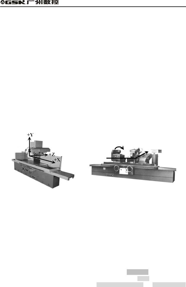
1.1.3.1 The differences between the coordinate systems
Based on the Cartesian coordinate system, the coordinate system of GSK928GA CNC system is Y/Z one, X is normally the hydraulic control axis without displaying the position; while the coordinate system of GSK928GE CNC system is X/Z one. The coordinate system is shown as the following figures:
+C
+X
+Z
Fig. 1-1 The machine coordinate system of the surface grinding machine
Fig.1-2 The machine coordinate system of the cylindrical grinding machine
Moreover, the outer grinding machine belongs to the rotational machine. The cross section of its work piece is normally round, and the dimensions marked on the machining drawing are diameter and the radius. For the user to edit the machining program based on the machining drawing of the part, GSK928GE cylindrical grinding machine CNC system provides the radius and diameter programming. However, the part drawing of the surface grinding machine doesn’t have the problem of the diameter dimension, therefore, GSK928GA only provides the radius programming.
1.1.3.2 Differences between I/O interface definitions
About GSK928GA and GSK928GE, I/O interface definition corresponds to PLC address. The tool clamp of the surface grinding machine is the electromagnetic chuck, while that of the outer grinding machine is the head and tail stocks. Therefore, in PLC definitions, Head stock is displayed on the status bar of GSK928GE cylindrical grinding machine CNC system, while Chuck is displayed on the status bar of GSK928GA surface grinding machine; Head stock motor control and Head stock motor
3
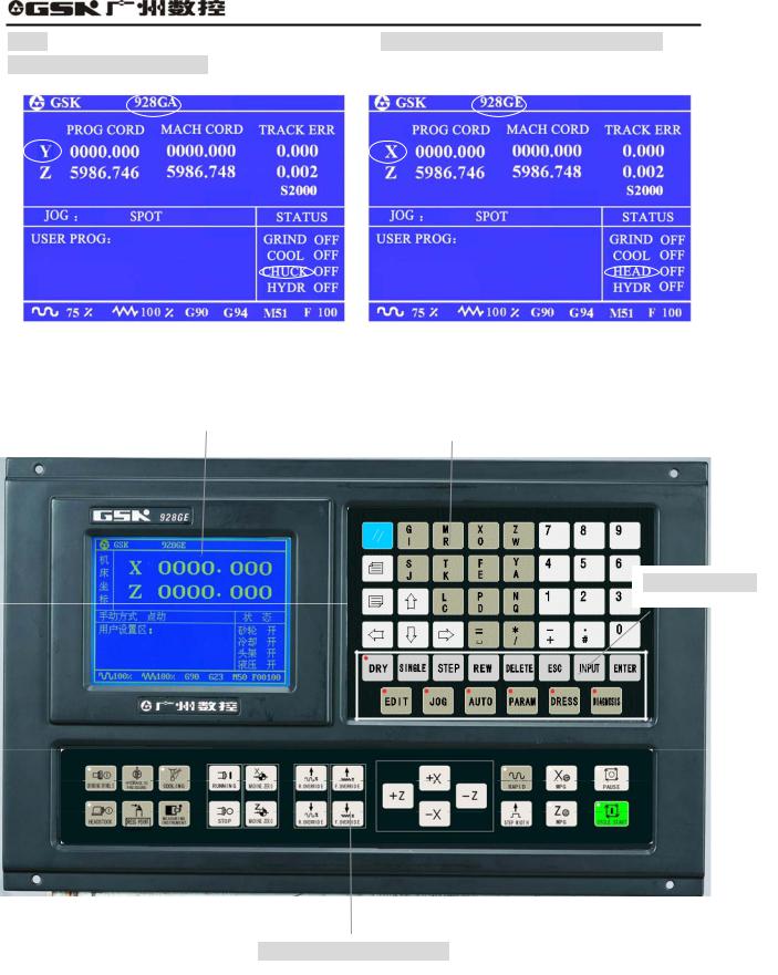
GSK928GA/GE Grinding Machine CNC System Operator’s Manual
alarm are defined in PLC of GSK928GE, while Electromagnetic chuck magnet control and Electromagnetic chuck alarm are defined in GSK928GA, which are shown as the following figures:
1.2 Introduction of system operation panels
|
|
|
|
|
|
Prompt screen |
|
|
Address keypad |
|
|
|
|
|
Function keypad
Operation panel of machine
Fig. 1-3 Introduction of system operation panel
(1)LCD monitor: The top left part of the system is blue LCD, the resolution is 320 X 240 lattices, which is for prompt of Chinese menu status of system, operational information and fault alarm.
4
GSK928GA/GE Grinding Machine CNC System Operator’s Manual
(2)Operation panel: The key is set, according to customer’s requirement, and control the machine to finish the various accessorial function and basic operation;
(3)Address keys: English letter input of part program field address;
(4)Functional keys: Various graphic symbol function key is set according to CNN machine graphic symbols;
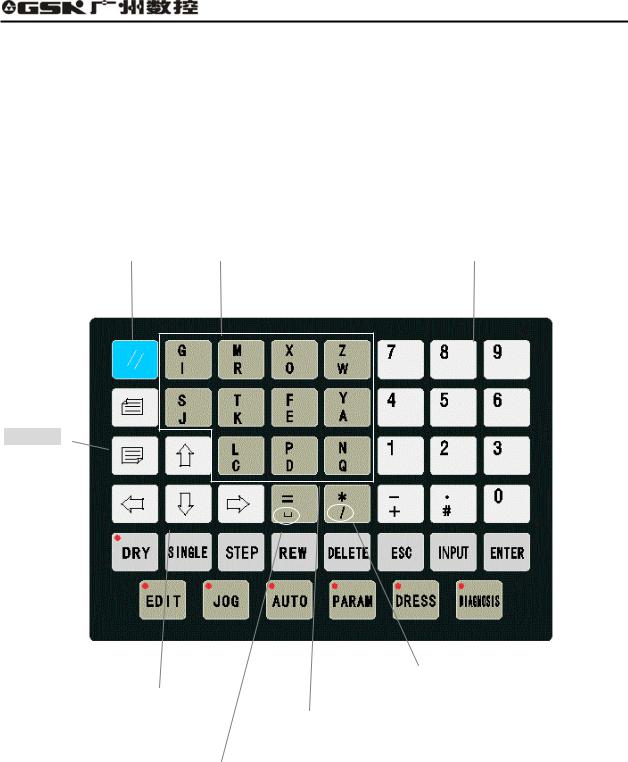
1.2.1 Introduction of the address keypad panel
Reset key |
|
Address keys |
|
Numerical keys |
Page keys
|
|
|
|
|
|
Skip |
|
|
|
|
|
Cursor keys |
|
|
|
|
|
|
|
|
|
|
|
|
|
|
|
|
|
|
|
|
|
||
|
|
|
|
|
|
|
|
|
|||
|
|
|
|
|
Double address key |
|
|
|
|
||
|
|
|
|
|
|
|
|
|
|
|
|
|
|
Space key |
|
z |
|
|
|
|
|||
|
|
|
Prompt the address code which is above the address |
||||||||
|
|
|
|||||||||
|
|
|
|
|
|
|
|
||||
|
|
|
|
|
key when press this key at the first time; |
||||||
|
|
|
|
z |
|
|
|
||||
|
|
|
|
Prompt the address code which is below the |
|||||||
|
|
|
|
|
|
|
|||||
|
|
|
|
|
address key when press the key again. |
||||||
|
|
|
|
|
|
|
|
|
|
|
|
Fig. 1-4 Address keypad panel
5
GSK928GA/GE Grinding Machine CNC System Operator’s Manual
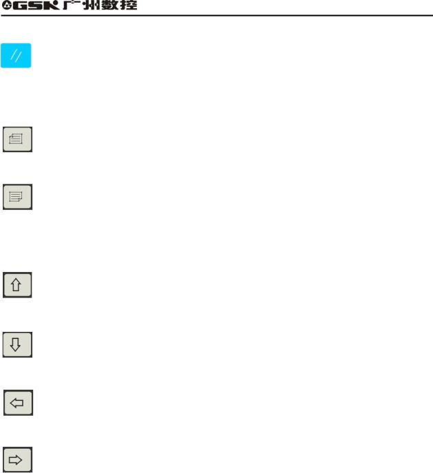
(1) Reset key
System reset key
All the movement of shaft stops when the system resets. All axis output function doesn’t work, and the machine stops running and prompts electrified status.
(2) Page keys:
Page up:
Turn a page up to search the program or parameter in the Edit/Para (parameter) mode. Change the type of displayed coordinate system in Auto/Jog mode.
Page down:
Turn a page down to search the program or parameter in the Edit/Para (parameter) mode. Display/hide the follow error in Auto/Jog mode.
3 Cursor control keys
The cursor moves upward:
Move the cursor to one upper row in the Edit/Para mode. The brightness of LCD is enhanced in Jog mode.
The cursor moves downward:
Move the cursor to the next row in Edit/Para mode. The brightness of LCD fades in Jog mode.
The cursor moves left:
Move the cursor to left in a character space in Edit mode. Delete the last input figures during the status of data input.
The cursor moves right:
The cursor moves to right in a character space in Edit mode.
4 Address key
Input the English letter of the part program field address.
6
GSK928GA/GE Grinding Machine CNC System Operator’s Manual
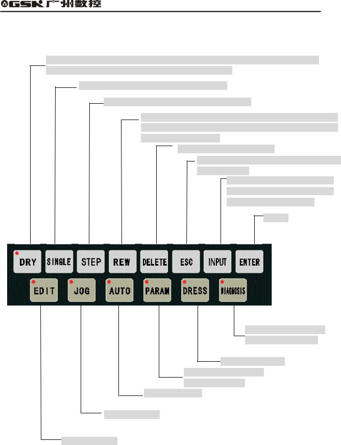
1.2.2 Introduction of the panel with function keys
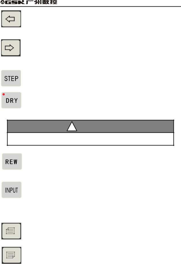
Select the dry run in Auto mode. The cursor can be directly moved to the initial character of this line during editing the machining program.
In Auto mode, select single/continuous mode.
In Manual mode, switch between step and jog.
Switch the input mode (insert/rewrite) during editing the machining program; In Auto mode, return to the initial line of the machining program.
Delete the digit, letter or block.
Cancel the currently input various data or exit from the mode.
Input the various data or select the program to be edit or run and create a new user program.
Confirm
Select the diagnosis mode or program PLC.
Select Dress mode Select the display or setting para. mode.
Select Auto mode.
Select Jog mode.
Select Edit mode.
Fig. 1-5 Panel of function keys
7
GSK928GA/GE Grinding Machine CNC System Operator’s Manual
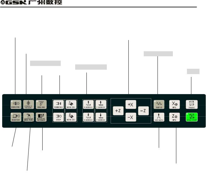
1.2.3 Introduction of the machine operation panel
|
|
|
|
|
|
|
|
|
|
|
|
|
|
|
|
|
|
|
|
Grinding wheel switch |
|
|
|
|
|
|
|
|
|
|
|
|
|
|
|||
|
|
|
|
|
|
|
|
|
|
|
|
|
|
|
||||
|
|
|
|
Spindle control |
|
|
|
|
|
|
|
|||||||
|
|
|
|
|
|
|
|
|
|
|
|
|
|
|
||||
|
|
|
|
|
|
|
|
|
|
|
|
|
|
|
||||
|
|
|
|
|
|
|
|
|
|
|
|
|
|
|
|
|
|
|
|
|
|
|
|
|
|
|
|
|
|
|
|
|
|
Manual direction key |
|
||
|
|
|
|
|
|
|
|
|
|
|
|
|||||||
|
|
|
Hydraulic |
|
|
|
|
|
|
|||||||||
|
|
|
|
|
|
|
||||||||||||
|
|
|
|
|
|
|
|
|
|
|
|
|
|
|
|
|
||
|
|
|
|
|
|
|
|
|
|
|
|
|
|
|
|
|||
|
|
|
pressure switch |
|
|
|
|
|
|
|
|
|
||||||
|
|
|
|
|
|
|
|
|
|
|
|
|
||||||
|
|
|
|
|
|
|
|
|
|
|
|
|
|
|
|
Rapid feed key |
||
|
|
|
|
|
|
|
|
|
|
|
|
|
||||||
|
|
|
|
|
|
|
|
|
|
|
|
|
|
|
|
|
|
|
|
|
|
|
|
|
|
|
|
|
|
|
|
|
|
|
|
|
|
Cooling switch
Rapid override
Pause
|
|
|
|
|
|
|
|
|
|
|
|
|
|
|
|
|
|
|
|
|
|
|
|
|
|
|
|
|
|
|
|
|
|
|
|
|
|
|
|
|
|
|
|
|
|
|
|
|
|
|
|
|
|
|
|
|
|
|
|
|
|
|
|
|
|
|
|
|
|
|
|
|
|
|
|
|
|
|
|
|
|
|
|
|
|
|
|
|
|
|
|
|
|
|
|
|
|
|
|
|
|
|
|
|
|
|
|
|
|
|
Machine-head motor |
|
|
|
|
|
|
|
Feedrate override |
|
|
|
Step width |
|
|
|
Cycle start |
|
|||
Measuring |
|
|
|||||||||||||||||||
|
|
|
|
|
|
|
|
|
|
|
|
|
|
|
|
|
|
|
|
|
|
|
|
|
|
|
|
|
|
increase/reduce |
|
|
|
|
|
|
|
|
|
|
|
||
|
|
|
|
|
|
|
|
|
|
|
|
|
|
|
|
|
|
|
|||
|
|
|
|
|
|
|
|
|
|
|
|
|
|
|
|||||||
|
|
|
|
|
|
|
|
|
|
|
|
|
|
|
|||||||
|
|
|
|
instrument control |
|
|
|
|
|
|
|
|
|
||||||||
|
|
|
|
|
|
|
|
|
|
|
|
|
|
|
|
|
|
|
|
||
|
|
|
|
|
|
|
|
|
|
|
|
|
|
|
|
|
|
|
|
|
|
|
|
|
|
|
|
X/Z MPG |
|
|
|
Mechanical zero return |
|
|
|
|
|
|
|
|
|
|
|
|
|
|
|
|
|
Dress point |
|
|||||
|
|
Fig. 1-6 Machine operation panel |
|
|||
|
|
|
|
|||
8
GSK928GA/GE Grinding Machine CNC System Operator’s Manual
CHAPTER 2 SYSTEM BASIC OPERATION
2.1 System power on/off
After connecting the external power supply, switch on the main power supply of machine. During the situation, the machine is not started. Press the start button in the accessorial machine operation panel of GSK928GE grinding machine CNC system and turn on the power supply of CNC system and external drive. After system detects each configuration work is OK, then, the machine is allowed to operate.
2.1.1 Power on
The steps of turning on CNC system:
1. Switch on the main switch of power supply, and turn on the system.
(1) System starting initialization
After switching on the system and initializing at the first time, the screen is displayed the version numbers of software and hardware, which is shown in the right figure:
After initializing the system, the system checks PLC program. If PLC program is not correct, the system shows the start-up screen and press any keys except reset key  , the system comes into debugging mode, then, the movement function does not work. If PLC program is OK, the system starts initializing DSP.
2 DSP initialization
After the system initializes at the first step, and PLC program is normal, it initializes DSP, if it is normal, and the screen is displayed “INITIALIZING DSP……OK!”
The start-up screen prompts when finish starting the system.
9

GSK928GA/GE Grinding Machine CNC System Operator’s Manual
If DSP initialization fails, the screen shows:
Press  , the system tries to initialize DSP again. Press other key, the system comes into debugging mode and shows the start-up screen.
2. After system finishes initializing, the screen Shows the trademark of GSK, and press any key except reset key  , the system comes into working mode.
2.1.2 Debugging mode
If any mistake in PLC program or failure of DSP initialization at the start stage, the system enters debugging mode. When emergency stop alarms, press for 5 seconds, the system enters debugging mode. The movement function of the system does not work in the debugging mode, and the system can not execute the relevant operation regarding to movement. The user can debug the system, find the fault, and modify the parameter, the machining and PLC programs. In Jog/ Auto mode, the system reminds the users that the system enters debugging by displaying the “debugging” in the status bar under the working mode.
As above figure shows, in the debugging mode, the user can modify PLC program in the diagnose mode. After detection of PLC program, press and restart the system, it enters working mode.
10
GSK928GA/GE Grinding Machine CNC System Operator’s Manual
2.1.3Power off
(1)Press the switch of CNC power supply, cut off power supply, and the system turns off.
(2)Cut off the machine main switch of power supply.
2.1.4Initializing CNC system
If power on the system at the first time, the initialization is operated according to the following steps:
Press and hold  and
and  at the same time, first release
  , after 3 seconds, then release , the system completes the parameter initialization. Then, the parameter of the machine is set as internal initialization of CNC system; refer to introduction of parameter about the details.
Initialization of system space:
●If the password is right, enter Edit mode, press  and input “-01”, then press
  , it reminds
Sure to delete program? And press to specify.
Initialization of system PLC:
●If the password is right, enter diagnosis state, then press |
for two seconds and it reminds |
|
PLC initialization completes! |
|
|
2.2 Machine zero return (HOME)
Every machine sets one point as its zero point. After power on or reset each time, the worktable can return to the zero point of machine, and return to the machining start point, then, the cumulative errors are eliminated. The worktable returns to the machine’s zero point before machining, then, specify the start point of machining and record the coordinate system of the machining start point which was recorded last time. After power off each time, the machine returns to the zero point and then comes to the machining start point which was recorded last time; finally, the program starts. Therefore, it can avoid the situation that the system coordinate system is not consistent with the actual position which may be moved by the operators after power off, and the accident may occur if the program starts without specifying the machining start point after power on the machine.
The function is that “whether it must return zero after CNC system power on, again or resetting, and then execute machining through selecting the parameter. Regarding to the details, refer to Bit 4 and 5 in the parameter 3.
 Return to zero point of machine X axis
Press  in Jog mode, the system prompts “X back to zero?”
Press |
, X axis rapidly returns to the machine zero point at rapid feedrate which is set in the |
parameter. |
|
 Return to zero point of machine Z axis
Press  in Jog mode, the system prompts “Z back to zero?”
11

GSK928GA/GE Grinding Machine CNC System Operator’s Manual
Press  , Z axis returns to the machine zero point at rapid speed which is set in the parameter. Regarding to the method and process of the return to machine zero point, refer to 6.1.5.1.
REMARK
1.The movement direction of machine returning to zero point is set by parameter Home Polar X and Home Polar Z of parameter P041. The grinding wheel base should be kept at the reverse direction of the switch during machine returns to the zero point.
2.Without the reference position switch on the machine, do not use the function of machine returning to zero function, otherwise, accident may occur because the grinding wheel base is moving at the high speed all the time without switch for reducing the speed.
3.Pay attention to it that during the machine return to zero, firstly the machine tries to return the X axis where the grinding wheel motor is installed and the switch should be fit in the other side which is far away from the Z axis work table.
2.3Emergency stop
There is an external emergency input port in the system input interface. The user should connect the normally closed contract point, which is on the emergency stop of the red mushroom on the machine panel, with the emergency input port. In the emergency situation, please press the emergency stop, the system enters emergent status; all the feeds stop, and the spindle of grinding wheel, switching value control and so on are edited by user through PLC. For safety, spindle and relevant equipment are closed. About the editing mode, refer to some chapters of PLC program section. The screen flickers and prompts as the figure 2.1 shows:
Fig. 2-1 Emergency stop alarm
Rotate the emergency switch according to the direction of an arrow, the emergency stop button automatic springs up, then, press the reset key and restart the system, the system can come back to the normal working status. If the system has no external emergency stop button, when the emergency stop alarms, press for a while, the system can enter the debugging mode. Then, modify PLC program, take the inverse value of the emergency stop signal and restart the system.
12

GSK928GA/GE Grinding Machine CNC System Operator’s Manual
2.4 Alarm
2.4.1 Limit switch alarm
The system can check limit switches if the machine has installed. When the socket is moved and the limit switch is pressed, the feeding stops but other miscellaneous function is still on, the program stops running, and the grinding wheel spindle and switching value control and so on are set by the user through PLC editing. When it alarms, the limit switch alarm information of corresponding axes is displayed at the top right corner.
After the limit switch alarms, Jog mode can be selected. Press “cancel limit”, meanwhile, press the manual feeding key or enter MPG operation, which is opposite to the limit direction, then, exit the limit and the limit switch alarm automatically exits from the screen.
2.4.2 Software limit alarm
The system sets the limit range, and if the machine exceeds the setting value, the system reminds axis software limit alarm, at the same time, press “limit release” and the corresponding direction keys, it moves again. If it still exceeds the limit setting value, the machine can not respond in the exceeded range.
2.4.3 Emergency retraction alarm
Using axis emergency retraction function can solve the problem of emergency retraction, and cancel the alarm by releasing the limit key.
2.4.4 Drive unit alarm
When the alarm output signal of drive connects with CNC system and drive alarms, the system cuts off all feeding operation automatically, and the screen also prompt X axis drive alarm or Z axis drive alarm. The system stops running and closes the entire output signal which is specified by PLC. Please check the drive and relevant connection shoot trouble and switch on again.
2.4.5 Other alarms
It prompts in the screen in Chinese if CNC system alarms, and then it can be dealt with based on the message. When many alarms occur at the same time, the system prompts in interval of 3 seconds, and also calls the alarm information through pressing page down key in the diagnosis mode, and it can save the latest 8 pieces of information.
13
GSK928GA/GE Grinding Machine CNC System Operator’s Manual
2.5 LCD brightness adjustment
The brightness of GSK928GE CNC system LCD can be adjusted by keys to reach the best visual effect. The method is as below:
(1) Switch CNC system to Jog mode.
(2) Press , the brightness of LCD screen becomes brighter or darker, and the result is locked automatically. After the system power on again or reset, the brightness of LCD screen is kept the same state before power off.
(3) If the temperature of environment changes obviously, the specialty affects the brightness of LCD, which is not the fault of CNC system. And the same brightness adjustment may cause different effect; therefore, it requires readjustment to reach the best effect.
14

GSK928GA/GE Grinding Machine CNC System Operator’s Manual
CHAPTER 3 EDIT MODE
3.1 Edit mode
The Edit mode is to manually input or rewrite the part program through system operation panel. In the Edit mode, the part program can be created, chosen or deleted through keypad; also, the selected part program content can be inserted, edited or deleted. Moreover, via the RS232 communication interface can connect with the serial interface of universal PC, then, transmit the part program of system to the external computer, vise versa.
When the user edits the program, the system checks the right of user. The user possesses the right to edit the program. The user can input correspondent password in the Para mode to change the right of the user. Otherwise, the screen prompts User has no right!
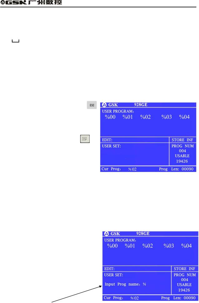
● Press Edit mode key
zEdit mode interface
a. All the present registered part program
names;
b.Usable memory bytes;
c.They bytes for the present program.
The meaning and usage of EDIT key in Edit mode:
Cursor moving upward key:
Press the key each time, the cursor moves to the first character behind last block number. Press the key without releasing, the key continuously moves up till the first program line;
otherwise, the key is released.
Cursor moving downward key
Press the key each time, the cursor moves to the first character of next program row. Press the key without releasing, the key continuously moves up till the last program line; otherwise, the key is released.
15
GSK928GA/GE Grinding Machine CNC System Operator’s Manual
Cursor moving to left key
Press the key each time, the cursor is moved by one character to left side. Press the key without releasing, the cursor continuously moves towards the left side until the first
character of the same program line, otherwise, the key is released.
Cursor moving to right key
Press the key each time, the cursor is moved by one byte to right side. Press the key without releasing, the cursor continuously moves toward the right side until the first
character of the same program line, or the key is released.
The cursor moves to the end of the program line.
The cursor moves toward to the first letter after program number.
REMARK
Cursor—the symbol that shows the character which can be edited at present.
Insert/rewrite key
The key is for changing the edit input mode. Press key for each time, the input method is switched between insert and rewrite, and the cursor prompt changes correspondingly.
The cursor of inserting is a flickering short line and the cursor of rewriting is a flickering square shape.
Input key
Press input key each time, and it inputs the program number in two digits, the new program can be created, selected, or the exist program and all programs can be
deleted.
Page up
It prompts the content of last page when searching the list of program number.
Page down
It prompts the program content of next page when searching the list of program number.
16
GSK928GA/GE Grinding Machine CNC System Operator’s Manual
Double function definition key:
Each key has two definitions, press the key for the first time, then it is the first definition value, that is
G |
M X |
Z |
S |
T F Y L P N |
= * — . Press the same key for the second time, |
||
system changes into the second definition value, that is I R O |
W J |
K E A C D Q # |
|||||
/ |
+ |
. If |
the |
same key is pressed |
continuously, the input |
value is |
changed from the first |
definition value to the second one or the second to the first. Among them, the “/” is skip block key, “  ”is space key. But under special working mode, if the key has one definition, then the key is switch to single function key automatically.
3.2 Part program directory search
Through part program directory searches, the users can search all stored part program number, and the remaining bytes of the part program storage and all part program name list in the Edit mode.
(1)Press  in the editing mode or press or
  during program edit.
(2)Each screen can prompt 20 program names. When the part programs of storage exceed 20,
it can prompt by pagination. Then, press |
, |
and turn to the next page, it prompts the list of program numbers in the next page.
3.3 Part program management
3.3.1 Creating a new part program
(1)Press  under the status of part program directory search;
(2)Input program numbers of two digits from keypad, which does not exist in the directory list, as new program number;
(3)Press  ;
;
(4)After creating the new part program, the system
enters program edit state automatically.
For example:
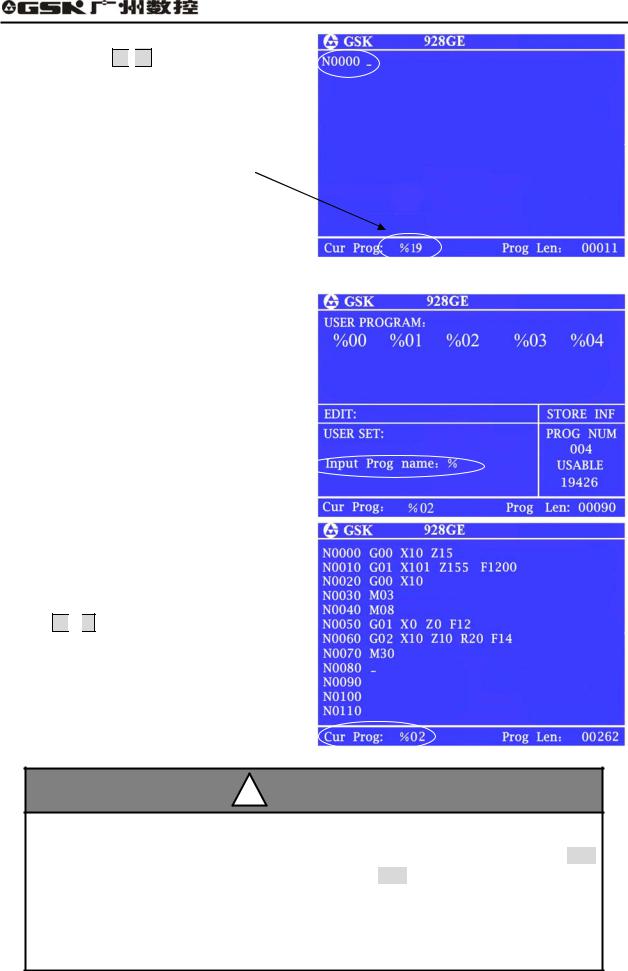
Create No. 19, which is new program number.
a.Press  and enter Edit mode;
b.Press  , the screen is displayed
Input prog number: % ;
17
GSK928GA/GE Grinding Machine CNC System Operator’s Manual
c.Press digit key 1 
 9
9
d.Press  , No. 19 program number is created. Block number is generated automatically
Current program number is displayed: %19
3.3.2 Selecting a part program
(1)Press  under the status of part program directory search;
(2)From keypad, input the selected program
number;
(3)Press  ;
;
(4)After selecting the part program, and prompt the content, then, it enters Edit mode.
For example: select No. %02 program
a.Press  and enter the Edit mode;
b.Press  and screen prompts Input prog number: ;
c.Input 0 
 2 ;
2 ;
d.Press  , program number % 02 is selected.
REMARK
1.CNC system is powered on for the first time, it enters the Edit mode or system part program storage area without any content, then, the system creates and selects %00 automatically. After system initialization, it also chooses %00 as present program.
2.After system selects one program, the program can only be changed through part program selection. Once the program is selected, it always keeps same. Even power is off, the program number can not be changed.
18
 Loading...