


 In this user manual we have tried to describe the matters concerning the operation of this CNC system to the greatest extent. However, it is impossible to give particular descriptions for all unnecessary or unallowable operations due to length limitation and products application conditions Therefore, the items not presented herein should be regarded as “impossible” or “unallowable”.
 Copyright is reserved to GSK CNC Equipment Co., Ltd. It is illegal for any organization or individual to publish or reprint this manual. GSK CNC Equipment Co., Ltd. reserves the right to ascertain their legal liability.

GSK988T Turning CNC System User Manual
Preface
Your Excellency,
We are honored by your purchase of this GSK 988T Turning CNC System made by GSK CNC Equipment Co., Ltd.
This book is User Manual “Programming and Operation”.
To ensure safe and effective running, please read this manual carefully before installation and operation.
Warning
 Accident may occur by improper connection and operation This system can only be operated by authorized and qualified personnel.
Special caution:
The power supply fixed on/in the cabinet is exclusively used for the CNC system made by GSK.
It can't be applied to other purposes, or else it may cause serious danger!
II

Contents
Cautions
■Delivery and storage
●Packing box over 6 layers in pile is unallowed.
●Never climb the packing box, stand on it or place heavy objects on it.
●Do not move or drag the products by the cables connected to it.
●Forbid collision or scratch to the panel and display screen.
●Avoid dampness, insolation and drenching.
■Open-package inspection
●Confirm that the products are the required ones.
●Check whether the products are damaged in transit.
●Confirm that the parts in packing box are in accordance with the packing list.
●Contact us in time if any inconsistence, shortage or damage is found.
■Connection
●Only qualified personnel can connect the system or check the connection.
●The system must be earthed, and the earth resistance must be less than 0.1Ω. The earth wire cannot be replaced by zero wire.
●The connection must be correct and firm to avoid any fault or unexpected consequence.
●Connect with surge diode in the specified direction to avoid damage to the system.
●Switch off power supply before plugging out or opening electric cabinet.
■Troubleshooting
●Switch off power supply before troubleshooting or changing components.
●Check the fault when short circuit or overload occurs. Restart can only be done after troubleshooting.
●Frequent switching on/off of the power is forbidden, and the interval time should be at least 1 min.
III

GSK988T Turning CNC System User Manual
ANNOUNCEMENT!
zThis manual describes various possibilities as much as possible. However, operations allowable or unallowable cannot be explained one by one due to so many possibilities that may involve with, so the contents that are not specially stated in this manual shall be regarded as unallowable.
WARNING
zPlease read this manual and a manual from machine tool builder carefully before installation, programming and operation, and strictly observe the requirements. Otherwise, products and machine may be damaged, workpiece be scrapped or the user be injured.
CAUTION
zFunctions, technical indexes (such as precision and speed) described in this user manual are only for this system. Actual function configuration and technical performance of a machine tool with this CNC system are determined by machine tool builder’s design, so functions and technical indexes are subject to the user manual from machine tool builder.
zThough this system adopts standard operation panel, the functions of the keys on the panel are defined by PLC program (ladder diagram). It should be noted that the keys functions described herein are for the standard PLC program (ladder diagram).
zFor functions and effects of keys on control panel, please refer to the user manual from machine tool builder.
IV

Contents
Safety Responsibility
Manufacturer’s Responsibility
——Be responsible for the danger which should be eliminated and/or controlled on design and configuration of the provided CNC systems and accessories.
——Be responsible for the safety of the provided CNC systems and accessories.
——Be responsible for the provided information and advice for the users.
User’s Responsibility
——Be trained with the safety operation of CNC system and familiar with the safety operation procedures.
——Be responsible for the dangers caused by adding, changing or altering to the original CNC systems and the accessories.
——Be responsible for the failure to observe the provisions for operation, adjustment, maintenance, installation and storage in the manual.
This manual is subject to change without further notice.
This manual is reserved by end user.
We are full of heartfelt gratitude to you for supporting us in the use of GSK’s products.
V

GSK988T Turning CNC System User Manual
VI
|
|
Contents |
|
|
|
|
Contents |
|
PROGRAMMING .......................................................................................................................... |
1 |
|
Chapter I |
Programming Fundamentals ............................................................................................ |
3 |
1.1 |
GSK988T Introduction ........................................................................................................ |
3 |
1.2 |
CNC system of machine tools and CNC machine tools ...................................................... |
5 |
1.3 |
Programming Fundamentals............................................................................................... |
7 |
1.3.1 |
Coordinates definition ............................................................................................... |
7 |
|
1.3.2 |
Increment system ..................................................................................................... |
9 |
|
1.3.3 |
Max. travel .............................................................................................................. |
10 |
|
1.3.4 |
Reference position.................................................................................................. |
10 |
|
1.3.5 |
Machine coordinate system .................................................................................... |
10 |
|
1.3.6 |
Workpice coordinate system................................................................................... |
11 |
|
1.3.7 |
Local coordinate system ......................................................................................... |
11 |
|
1.3.8 |
Interpolation function .............................................................................................. |
11 |
|
1.4 |
Coordinate Value and Dimension...................................................................................... |
12 |
|
1.4.1 Absolute programming and incremental programming ........................................... |
12 |
||
1.4.2 Diameter programming and radius programming ................................................... |
13 |
||
1.4.3 |
Decimal programming............................................................................................. |
14 |
|
1.4.4 Conversion between the metric and the inch.......................................................... |
14 |
||
1.4.5 Linear axis and rotary axis ...................................................................................... |
15 |
||
1.5 |
Structure of an NC Program.............................................................................................. |
15 |
|
1.5.1 |
Program name ........................................................................................................ |
16 |
|
1.5.2 |
Block format............................................................................................................ |
16 |
|
1.5.3 |
Word ....................................................................................................................... |
17 |
|
1.5.4 |
Block number.......................................................................................................... |
26 |
|
1.5.5 Main program and subprogram............................................................................... |
26 |
||
1.6 |
Program Run .................................................................................................................... |
27 |
|
1.6.1 Sequence of program run ....................................................................................... |
27 |
||
1.6.2 Execution sequence of word................................................................................... |
28 |
||
Chapter II |
G Commands ................................................................................................................ |
29 |
|
2.1 |
Summary .......................................................................................................................... |
29 |
|
2.1.1 |
G command classification....................................................................................... |
29 |
|
2.1.2 |
Omitting word input................................................................................................. |
31 |
|
2.1.3 |
Related definitions .................................................................................................. |
33 |
|
2.2 |
Rapid Traverse (Positioning) G00 ..................................................................................... |
33 |
|
2.3 |
Linear Interpolation G01 ................................................................................................... |
34 |
|
2.4 |
Arc Interpolation G02, G03 ............................................................................................... |
35 |
|
2.5 |
Dwell G04 ......................................................................................................................... |
38 |
|
2.6 |
Cylindrical Interpolation 7.1............................................................................................... |
39 |
|
2.7 |
Polar Coordinate Interpolation G12.1, G13.1.................................................................... |
43 |
|
2.8 |
Metric/Inch Switch G20, G21 ............................................................................................ |
45 |
|
2.9 |
Stored Travel Check G22, G23 ......................................................................................... |
45 |
|
2.10 |
Skip Interpolation G31 .................................................................................................... |
46 |
|
2.11 |
Automatic Tool Offset G36, G37 ................................................................................... |
48 |
|
2.12 |
Reference Position Function........................................................................................... |
50 |
|
VII

GSK988T Turning CNC System User Manual
|
2.12.1 Reference position return G28.............................................................................. |
50 |
|
|
2.12.2 2nd, 3rd, 4th reference position return G30 ............................................................. |
51 |
|
2.13 |
Related Function of Coordinate System ......................................................................... |
52 |
|
|
2.13.1 Selecting machine coordinate system position G53 ............................................. |
53 |
|
|
2.13.2 Workpiece coordinate system setting G50 ........................................................... |
54 |
|
|
2.13.3 Workpiece coordinate system selection command G54 G59............................. |
55 |
|
|
2.13.4 Local coordinate system setting G52.................................................................... |
57 |
|
|
2.13.5 Level selection command G17 G19 ................................................................... |
59 |
|
|
2.13.6 Exact stop mode G61/cutting mode G64 .............................................................. |
59 |
|
2.14 |
Fixed Cycle Command ................................................................................................... |
60 |
|
|
2.14.1 Axial cutting cycle G90 ......................................................................................... |
60 |
|
|
2.14.2 Radial cutting cycle G94 ....................................................................................... |
63 |
|
2.15 |
Multiple Cycle Commands .............................................................................................. |
66 |
|
|
2.15.1 Axial Roughing Cycle G71.................................................................................... |
66 |
|
|
2.15.2 |
Radial Roughing Cycle G72............................................................................... |
72 |
|
2.15.3 Closed Cutting Cycle G73 .................................................................................... |
77 |
|
|
2.15.4 |
Finishing Cycle G70 ............................................................................................. |
82 |
|
2.15.5 Axial Grooving Multiple Cycle G74 ....................................................................... |
83 |
|
|
2.15.6 Radial Grooving Multiple Cycle G75..................................................................... |
86 |
|
|
2.15.7 Notes for multi cycle machining ............................................................................ |
89 |
|
2.16 |
Threading Cutting ........................................................................................................... |
90 |
|
|
2.16.1 Thread Cutting with Constant Lead G32............................................................... |
90 |
|
|
2.16.2 Thread cutting with variable lead G34 .................................................................. |
93 |
|
|
2.16.3 Thread cutting cycle G92...................................................................................... |
95 |
|
|
2.16.4 Multiple thread cutting cycle G76.......................................................................... |
97 |
|
2.17 |
Constant Surface Speed Control G96, Constant Rotational Speed Control G97..... |
103 |
|
2.18 |
Feedrate per Minute G98, Feedrate per Rev G99 ................................................... |
105 |
|
2.19 |
Drilling/Boring Fixed Cycle Command .......................................................................... |
106 |
|
|
2.19.1 End drilling cycle G83 /side drilling cycle G87 .................................................... |
107 |
|
|
2.19.2 End Boring CycleG85 / Side Boring Cycle G89 .................................................. |
111 |
|
|
2.19.3 |
Cancelling Drilling/Boring G80............................................................................ |
112 |
|
2.19.4 Notes for Drilling/Boring Cycle............................................................................ |
112 |
|
2.20 |
Tapping Cycle Command.............................................................................................. |
112 |
|
|
2.20.1 |
Tapping Mode ..................................................................................................... |
113 |
|
2.20.2 End Rigid Tapping Cycle (G84) / Side Rigid Tapping Cycle (G88)...................... |
114 |
|
|
2.20.3 End Common Tapping Cycle (G84) /Side Common Tapping Cycle (G88) .......... |
120 |
|
2.21 |
Automatic Chamfering Function.................................................................................... |
123 |
|
2.22 |
Macro Command .......................................................................................................... |
126 |
|
|
2.22.1 |
Variable............................................................................................................... |
126 |
|
2.22.2 |
System variable .................................................................................................. |
127 |
|
2.22.3 Operation and jump command ........................................................................... |
131 |
|
|
2.22.4 Macro program statement and NC statement..................................................... |
136 |
|
|
2.22.5 |
Macro program call............................................................................................. |
136 |
Chapter MSTF Commands..................................................................................................... |
139 |
||
3.1 |
M (Miscellaneous Function)............................................................................................ |
139 |
|
|
3.1.1 End of program M02............................................................................................. |
139 |
|
VIII

|
|
Contents |
3.1.2 End of program run M30....................................................................................... |
139 |
|
3.1.3 |
Program stop M00 ................................................................................................ |
139 |
3.1.4 |
Optional stop M01................................................................................................. |
140 |
3.1.5 |
Subprogram call M98 ......................................................................................... |
140 |
3.1.6 |
Subprogram Call M198......................................................................................... |
141 |
3.1.7 |
Return from Subprogram M99............................................................................ |
141 |
3.1.8The Following M commands for standard ladder(some functions modified by K
|
parameters)...................................................................................................................... |
142 |
|
|
3.1.9 |
M Commands defined by standard PLC ladder .................................................... |
143 |
3.2 |
Spindle Function ............................................................................................................. |
143 |
|
|
3.2.1 |
Spindle speed analog voltage control ................................................................... |
143 |
|
3.2.2 |
Spindle override .................................................................................................... |
144 |
3.3 |
Tool |
Function .................................................................................................................. |
144 |
|
3.3.1 |
Tool offset ............................................................................................................. |
144 |
|
3.3.2 |
Tool Life Management .......................................................................................... |
147 |
Chapter IV Tool Nose Radius Compensation............................................................................... |
151 |
||
4.1 |
Application ...................................................................................................................... |
151 |
|
|
4.1.1 |
Overview............................................................................................................... |
151 |
|
4.1.2 |
Imaginary tool nose direction ................................................................................ |
152 |
|
4.1.3 |
Compensation value setting.................................................................................. |
155 |
|
4.1.4 |
G40/G41/G42 command function ......................................................................... |
156 |
|
4.1.5 |
Compensation direction ........................................................................................ |
157 |
|
4.1.6 |
Cautions ............................................................................................................... |
159 |
|
4.1.7 |
Application ............................................................................................................ |
160 |
4.2 |
Tool |
Nose Radius Compensation Offset Path................................................................. |
161 |
|
4.2.1 |
Inner and outer side.............................................................................................. |
161 |
|
4.2.2 |
Tool traversing when starting tool ......................................................................... |
161 |
|
4.2.3 |
Tool traversing in Offset mode .............................................................................. |
163 |
|
4.2.4 |
Tool traversing in Offset canceling mode .............................................................. |
168 |
|
4.2.5 |
Tool interference check......................................................................................... |
169 |
|
4.2.6 |
Commands for canceling compensation vector temporarily ................................. |
171 |
|
4.2.7 |
Particulars............................................................................................................. |
174 |
OPERATION ........................................................................................................................... |
181 |
||
Chapter Overview..................................................................................................................... |
183 |
||
1.1 |
Operation Overview ........................................................................................................ |
183 |
|
1.2 |
System Setting................................................................................................................ |
184 |
|
1.3 |
Display ............................................................................................................................ |
185 |
|
1.4 |
System............................................................................................................................ |
187 |
|
|
1.4.1 |
System panel ........................................................................................................ |
187 |
|
1.4.2 |
System key definitions .......................................................................................... |
188 |
1.5 |
Machine Operation Panel ............................................................................................... |
190 |
|
|
1.5.1 |
Division of machine operation panel ..................................................................... |
190 |
|
1.5.2 |
State indicator and press key definition on the panel............................................ |
191 |
Chapter Power on, Power off and Safety Protection ................................................................ |
196 |
||
IX

|
|
GSK988T Turning CNC System |
User Manual |
|
|
|
|
2.1 |
Power on ........................................................................................................................ |
196 |
|
2.2 |
Power off......................................................................................................................... |
197 |
|
2.3 |
Overtravel Protection ...................................................................................................... |
197 |
|
2.4 |
Overtravel Protection in Memory Travel Limit ................................................................. |
197 |
|
2.5 |
Emergence Operation..................................................................................................... |
199 |
|
|
2.5.1 |
Reset .................................................................................................................... |
199 |
|
2.5.2 |
Emergency stop.................................................................................................... |
199 |
|
2.5.3 |
Feed hold.............................................................................................................. |
199 |
|
2.5.4 Cutting off power supply ....................................................................................... |
199 |
|
Chapter Windows ................................................................................................................... |
200 |
||
3.1 |
Position Display Window ................................................................................................ |
205 |
|
|
3.1.1 |
Absolute coordinate window ................................................................................. |
206 |
|
3.1.2 |
Relative coordinate display................................................................................... |
207 |
|
3.1.3 |
Machine coordinate display .................................................................................. |
208 |
|
3.1.4 |
Comprehensive coordinate................................................................................... |
208 |
|
3.1.5 Setting the relative coordinate .............................................................................. |
209 |
|
|
3.1.6 Switching between the mode and the comprehensive message .......................... |
210 |
|
|
3.1.7 |
Clearing workpiece count ..................................................................................... |
211 |
|
3.1.8 |
Clearing run time .................................................................................................. |
211 |
3.2 |
Program Window ............................................................................................................ |
212 |
|
|
3.2.1 Local directory and U disk directory...................................................................... |
212 |
|
|
3.2.2 |
MDI program......................................................................................................... |
213 |
|
3.2.3 |
Item/times ............................................................................................................. |
214 |
3.3 |
System Window .............................................................................................................. |
214 |
|
|
3.3.1 System parameter setting and rewriting window .................................................. |
215 |
|
|
3.3.2 Screw pitch compensation setting and rewriting window...................................... |
218 |
|
|
3.3.3 System message and operation authority levels .................................................. |
219 |
|
|
3.3.4 |
System file management ...................................................................................... |
222 |
|
3.3.5 |
Ladder diagram .................................................................................................... |
223 |
3.4 |
Setting Window............................................................................................................... |
229 |
|
|
3.4.1 |
Tool offset setting.................................................................................................. |
229 |
|
3.4.2 |
CNC setting window ............................................................................................. |
233 |
|
3.4.3 |
Macro variable window ......................................................................................... |
238 |
3.5 |
Message Window ........................................................................................................... |
239 |
|
|
3.5.1 Alarm message check window ............................................................................. |
240 |
|
|
3.5.2 Alarm record check window.................................................................................. |
241 |
|
|
3.5.3 |
Diagnosis window................................................................................................. |
242 |
|
3.5.4 |
Oscillograph window............................................................................................. |
245 |
|
3.5.5 |
GSK-CAN window ................................................................................................ |
248 |
3.6 |
Graph Window ................................................................................................................ |
249 |
|
|
3.6.1 |
Setting graph parameter ....................................................................................... |
249 |
|
3.6.2 |
Processing graph path.......................................................................................... |
250 |
|
3.6.3 |
Simulation graph................................................................................................... |
251 |
3.7 |
Help Windows................................................................................................................. |
252 |
|
Chapter Editing and Managing a Program ............................................................................. |
254 |
||
X
|
|
|
Contents |
|
|
|
|
4.1 |
Searching, Creating, Executing and Opening a Program ............................................... |
254 |
|
|
4.1.1 |
Searching a program ............................................................................................ |
254 |
|
4.1.2 |
Creating a program............................................................................................... |
254 |
|
4.1.3 |
Executing a program............................................................................................. |
255 |
|
4.1.4 |
Opening a program............................................................................................... |
256 |
4.2 |
Renaming, Outputting, Deleting and Arraying Programs, Saving a Program as ............. |
257 |
|
|
4.2.1 |
Renaming a program ............................................................................................ |
257 |
|
4.2.2 |
Saving a program as............................................................................................. |
258 |
|
4.2.3 |
Deleting a program ............................................................................................... |
259 |
|
4.2.4 |
Outputting a program............................................................................................ |
259 |
|
4.2.5 |
Arraying programs ................................................................................................ |
260 |
4.3 |
Editing and Rewriting a Program .................................................................................... |
260 |
|
|
4.3.1 |
Editing a program ................................................................................................. |
260 |
|
4.3.2 |
Rewriting a program ............................................................................................. |
261 |
|
4.3.3 |
Shortcut key.......................................................................................................... |
262 |
4.4 |
Block Comment............................................................................................................... |
263 |
|
4.5 |
Generating a Block Number............................................................................................ |
263 |
|
4.6 |
Background Editing a Program ....................................................................................... |
263 |
|
Chapter Manual Operation ..................................................................................................... |
264 |
||
5.1 |
Manual Reference Position Return ................................................................................. |
264 |
|
5.2 |
Manual Feed................................................................................................................... |
265 |
|
5.3 |
Increment Feeding .......................................................................................................... |
266 |
|
5.4 |
MPG Feeding............................................................................................................... |
...267 |
|
Chapter Auto Operation............................................................................................................ |
270 |
||
6.1 |
Auto Running .................................................................................................................. |
270 |
|
|
6.1.1 |
Selecting the running program.............................................................................. |
270 |
|
6.1.2 |
Program running ................................................................................................... |
271 |
|
6.1.3 |
Running from any block ........................................................................................ |
272 |
|
6.1.4 |
Skip....................................................................................................................... |
272 |
|
6.1.5 |
G31 skip ............................................................................................................... |
273 |
|
6.1.6 |
Stop auto running.................................................................................................. |
273 |
6.2 |
MDI Running................................................................................................................... |
274 |
|
|
6.2.1 Editing and running the program in MDI mode ..................................................... |
274 |
|
|
6.2.2 Running from any block ........................................................................................ |
275 |
|
|
6.2.3 |
Stop MDI running .................................................................................................. |
275 |
6.3 |
DNC Running.................................................................................................................. |
275 |
|
6.4 |
Auto Running Control...................................................................................................... |
278 |
|
|
6.4.1 Machine and miscellaneous function lock............................................................. |
278 |
|
|
6.4.2 |
Dry run.................................................................................................................. |
279 |
|
6.4.3 |
Single block running ............................................................................................. |
280 |
|
6.4.4 |
Feedrate override ................................................................................................. |
280 |
|
6.4.5 |
Rapid traverse override ........................................................................................ |
281 |
Chapter Tool Offset and Setting Tools .................................................................................... |
282 |
||
7.1 |
Setting the Tool Offset and the Wearing Values.............................................................. |
282 |
|
XI

|
|
GSK988T Turning CNC System |
User Manual |
|
|
|
|
|
7.1.1 |
Direct input method .............................................................................................. |
282 |
|
7.1.2 |
Measuring mode................................................................................................... |
283 |
|
7.1.3 |
+input mode.......................................................................................................... |
284 |
|
7.1.4 |
C input method ..................................................................................................... |
285 |
|
7.1.5 Clearing the offset value or the wearing value...................................................... |
286 |
|
7.2 |
Fixed-Point Tool Setting.................................................................................................. |
287 |
|
7.3 |
Trial Cut Toolsetting ........................................................................................................ |
287 |
|
7.4 |
Position Record .............................................................................................................. |
290 |
|
7.5 |
Automatic Tool Compensation ........................................................................................ |
290 |
|
Chapter Setting and Display Graphs ...................................................................................... |
292 |
||
8.1 |
Setting the Graph Parameter.......................................................................................... |
292 |
|
8.2 |
Path Graph Display and Operation ................................................................................. |
293 |
|
8.3 |
Simulation graph display and operation.......................................................................... |
294 |
|
Chapter U disk Use ................................................................................................................ |
296 |
||
9.1 |
Sending a Program......................................................................................................... |
296 |
|
9.2 |
Backup Value.................................................................................................................. |
297 |
|
|
9.2.1 |
System file backup ............................................................................................... |
297 |
|
9.2.2 |
Servo parameter backup ...................................................................................... |
298 |
Chapter Processing Examples ................................................................................................. |
301 |
||
10.1 Outer End Face Machining ........................................................................................... |
301 |
||
10.2 |
Compound Machining................................................................................................... |
304 |
|
Chapter Parameters ............................................................................................................... |
310 |
||
11.1 |
Parameters Related to System Setting ......................................................................... |
311 |
|
11.2 |
Parameters Related to Interfaces of Input and Output.................................................. |
311 |
|
11.3 |
Parameters Related to Axis Control/Setting Unit........................................................... |
311 |
|
11.4 |
Parameters Related to Coordinate System................................................................... |
315 |
|
11.5 |
Parameters Related to the Stroke Detection................................................................. |
317 |
|
11.6 |
Parameters Related to Feedrate................................................................................... |
320 |
|
11.7 |
Parameters Related to Control of Acceleration and Deceleration ................................. |
324 |
|
11.8 |
Parameters Related to Servo and Backlash Compensation ......................................... |
326 |
|
11.9 |
Parameters Related to Input/Output ............................................................................. |
330 |
|
11.10 Parameters Related to Display and Editing................................................................. |
332 |
||
11.11 Parameters Related to Programming .......................................................................... |
334 |
||
11.12 Parameters Related to Screw Pitch Error Compensation ........................................... |
336 |
||
11.13 Parameters Related to the Spindle Control................................................................. |
339 |
||
11.14 Parameters Related to the Tool Compensation........................................................... |
344 |
||
11.15 Parameters Related to the Canned Cycle................................................................. |
347 |
||
|
11.15.1 Parameter of the Drilling Canned Cycle............................................................ |
347 |
|
|
11.15.2 Parameters Related to the Thread Cutting Cycle.............................................. |
348 |
|
|
11.15.3 Parameters Related to the Combined Canned Cycle ....................................... |
348 |
|
11.16 Parameters Related to the Rigid Tapping.................................................................... |
349 |
||
11.17 Parameters Related to the Polar Coordinate Interpolation.......................................... |
351 |
||
11.18 Parameters Related to the User Macro Program ........................................................ |
352 |
||
XII
|
|
|
|
Contents |
|
|
|
|
|
11.19 Parameters Related to Skip Function.......................................................................... |
353 |
|||
11.20 Parameters Related to Graphic Display ...................................................................... |
355 |
|||
11.21 Parameters Related to Run Hour and Parts Count Display......................................... |
355 |
|||
11.22 Parameters Related to MPG Feed .............................................................................. |
356 |
|||
11.23 Parameters Related to PLC Axis Control .................................................................... |
357 |
|||
11.24 Parameters Related to Basic Function........................................................................ |
360 |
|||
11.25 Parameters Related to GSK-CAN Communication Function ...................................... |
361 |
|||
Appendix 1 |
Alarm List .................................................................................................................. |
363 |
||
1.1 |
Program Alarms (P/S Alarms) ......................................................................................... |
363 |
||
1.2 |
Parameter Alarms ........................................................................................................... |
372 |
||
1.3 |
Pulse Encoder Alarms..................................................................................................... |
373 |
||
1.4 |
Servo Alarms .................................................................................................................. |
373 |
||
1.5 |
Overtravel Alarms ........................................................................................................... |
373 |
||
1.6 |
Spindle Alarms ................................................................................................................ |
374 |
||
1.7 |
System Alarms................................................................................................................ |
374 |
||
1.8 |
Communication prompt on the operation panel .............................................................. |
375 |
||
1.9 |
GSK-CAN Communication Prompts ............................................................................... |
375 |
||
1.10 |
Servo Inner Alarms ....................................................................................................... |
377 |
||
Appendix 2 Standard Ladder Function Allocation......................................................................... |
381 |
|||
2.1 |
X, Y Addresses Definition................................................................................................ |
381 |
||
2.2 |
Standard Operation Panel............................................................................................... |
384 |
||
|
2.2.1 |
Address X ............................................................................................................. |
384 |
|
|
2.2.2 |
Address Y ............................................................................................................. |
386 |
|
2.3 |
Standard PLC Parameter Instruction .............................................................................. |
389 |
||
|
2.3.1 |
Parameter K.......................................................................................................... |
389 |
|
|
2.3.2 |
Parameter DT ....................................................................................................... |
390 |
|
|
2.3.3 |
Parameter DC....................................................................................................... |
391 |
|
|
2.3.4 |
Parameter D ......................................................................................................... |
391 |
|
2.4 |
PLC(Address A) Alarms (the Followings are Referred to V2.03b)................................... |
392 |
||
Appendix 3 |
Installation................................................................................................................. |
394 |
||
3.1 |
GSK988T Appearance Dimension .................................................................................. |
394 |
||
3.2 |
Machine Operation Panel MPU02A of GSK988T............................................................ |
395 |
||
3.3 |
Machine Operation Panel MPU02B Appearance dimension of GSK988T ...................... |
396 |
||
3.4 |
GSK988T-H Appearance Dimension............................................................................... |
397 |
||
3.5 |
Appearance Dimension of GSK988T-H Operation panel ................................................ |
397 |
||
Appendix 4 |
Operation List............................................................................................................ |
399 |
||
XIII

GSK988T Turning CNC System User Manual
XIV

Chapter 1 Programming Fundamentals
PROGRAMMING
Programming
1

GSK988T Turning CNC System User Manual
Programming
2
Chapter Programming Fundamentals
Chapter I Programming Fundamentals
1.1GSK988T Introduction
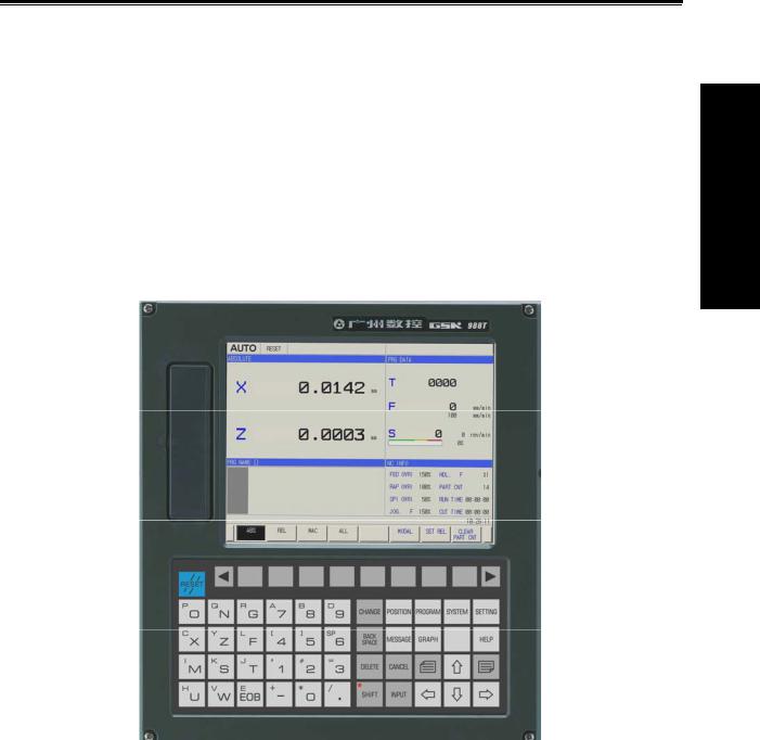
GSK988T is exclusive to the slant bed CNC turning machine and turning center with the horizontal and the vertical structures. It uses 400MHz high-performance process to control 5 feed axes(including Cs axis) and 2 spindles, communicates with the servo unit through GSK-CAN serial bus, and its matched servo motor uses the high-resolution absolute encoder to realize 0.1μm position precision, which can meet the requirements of high-precision turning and milling compound machining. It has the network interface to support the remote monitor and file transmission and to meet the network teaching and workshop management. GSK988T is the best choice for the slant bed CNC turning and turning center.
Fig. 1-1 GSK988T appearance
Technical characteristics
5 feed axes including Cs axis , 3-axis link, 2 analog spindles to realize the turning, milling compound machining
Command unit 1μm and 0.1μm, max. speed 60m/min max. speed 24m/min in 0.1μm Optional to GSK-CAN servo unit to read/write the servo parameter and monitor servo unit Extended I/O unit and GSK-CAN axis through serial bus
Nested many PLC programs, on-line editing, real-time monitoring PLC ladder Part programs edited on the background
Network interface, remote monitoring and file transmission
USB interface, U disc file operation, system allocation and software upgrading 8.4 inch truecolor LCD, two-dimensional motion path and solid graph display
Programming
3

Programming
GSK988T Turning CNC System User Manual
Technical specifications
Controllable axes
Max. controllable axes 5 including Cs axis Max. link axes 3
PLC controllable axes 5
Feed axis function
Least command unit 0.001mm, 0.0001mm
Least command range ±99999999× least command unit
Rapid traverse speed max. 60m/min in 0.001mm command unit, max. 24m/min in 0.0001mm command unit
Rapid override F0, 25%, 50%, 100% real-timing tuning Cutting feedrate:
0.01 mm/min 60000 mm/min or 0.01 inch/min 4000 inch/min G98: feed per minute 0.01 mm/rev 500 mm/r or 0.01 inch/rev 9.99 inch/rev G99: feed per revolution Feedrate override 0 150% 16-level real-time tuning
Interpolation mode: linear, arc, thread, polar interpolation, and rigid tapping
Thread function
Thread type: constant pitch straight thread/taper thread/end thread, variable pitch straight thread/taper thread/end thread
Thread head 1~99 heads
Thread pitch 0.01mm 500mm metric thread or 0.01inch 9.99inch inch thread Thread run-out thread lenght, angle, speed can be set
Acceleration/deceleration function
Cutting feed: linear, exponential Rapid traverse: linear
Thread cutting: linear, exponential
Initial speed, terminal speed and time of acceleration/deceleration are set by the parameter
Spindle function
2-channel 0V 10V analog voltage output 2-channel spindle encode feedback, double-spindle control
Spindle speed: spindle speed specified by S or PLC signal, its range: 0rpm 20000rpm Spindle override 50% 120% 8-level real-time tuning
Spindle constant surface control Rigid tapping
Tool function
Tool length compensation tool offset 99 groups
Tool wear compensation 99 groups of tool wear compensation data Tool nose radius compensation C type
Toolsetting mode: fixed-point toolsetting, trial-cutting toolsetting, reference position return toolsetting Offset execution mode: modifying coordinate mode, tool traverse mode
Precision compensation
Backlash compensation: compensation range (-9999~9999)× check unit
Memory pitch error compensation 1024 compensation points compensation point number of each is set by the parameter, each point compensation range (-700~700) × check unit
PLC function
13 basic commands, 30 functional commands
4

Chapter Programming Fundamentals
PLC ladder on-line edit, real-time monitoring
2-level PLC program, up to 5000 steps, the 1st level program refresh period
Many PLC programs up to 16 programs the current running PLC program can be selected
I/O unit
Basic I/O 40 input /32 output Operation panel I/O 96 input/96 output
Human-computer interface
Display in Chinese, English and others Two-dimensional tool path and solid graph display
Servo state monitoring
Servo parameter on-line allocation Real-time clock
On-line help
Operation management
Operation mode: Auto, Manual, Edit, MDI, DNC, MPG, Reference position return Multi-level operation Authorization Management
Alarm log Timed stop
Program edit
Program capacity 36M, 10000 programs including subprogram and macro program Edit mode: full-screen edit, part program edit on the background
Edit function searching, modifying and deleting program/block/word, copying/deleting block Program format: ISO code, word without blank space, relative coordinates, absolute coordinate compound programming
Macro command: statement macro command program
Program call: macro program call with parameters, 12-level subprogram nesting
Grammar check: executing the rapid grammar check for the program(do not run the program) after it has been edit
Communication function
RS232 interface: part program and parameter transmission, DNC machining, upgrading PLC program and system software U disc
USB U disc file operation, U disc file directly machining, upgrading PLC program and system software U disc
LAN remote monitoring, network DNC machining, file transmission, remotely upgrading PLC program, system software
Safety function
Emergency stop Hardware travel limit
Many storage travel checks Data backup and recover
1.2CNC system of machine tools and CNC machine tools
CNC machine tool is an electro-mechanical integrated product, composed of Numerical Control Systems of Machine Tools, machines, electric control components, hydraulic components, pneumatic components, lubricating, cooling and other subsystems (components), and CNC systems of machine tools are control cores of CNC machine tools. CNC systems of machine tools are made up of computerized numerical control(CNC), servo (stepper) motor drive devices, servo (or stepper) motor
Programming
5

Programming
GSK988T Turning CNC System User Manual
etc.
Operational principles of CNC machine tools: according to requirements of machining technology, edit user programs and input them to CNC, then CNC outputs motion control commands to the servo (stepper) motor drive devices, and last the servo (or stepper) motor completes the cutting feed of machine tool by mechanical driving device; logic control commands in user programs to control spindle start/stop, tool selections, cooling ON/OFF, lubricant ON/OFF are output to electric control systems of machine tools from CNC, and then the electric control systems control output components including buttons, switches, indicators, relays, contactors and so on. Presently, the electric control systems are employed with Programmable Logic Controller (PLC) with characteristics of compact, convenience and high reliance. Thereof, the motion control systems and logic control systems are the main of CNC machine tools.
The system has simultaneously motion control and logic control function to control two axes of CNC machine tool to move, and has PLC function. Edit PLC programs (ladder diagram) according to requirements of input and output control of machine tool and then download them to GSK988T Turning Machine CNC system, which realizes the required electric control requirements of machine tool, is convenient to electric design of machine tool and reduces cost of CNC machine tool.
Softwares used for controlling GSK988T Turning Machine CNC system are divided into system software (NC for short) and PLC software (PLC for short). NC system is used for controlling display, communication, edit, decoding, interpolation and acceleration/deceleration, and PLC system for controlling explanations, executions, inputs and outputs of ladder diagrams.
Standard PLC programs are loaded (except for the special order) when GSK980TDa Turning Machine CNC System is delivered, concerned PLC control functions in following functions and operations are described according to control logics of standard PLC programs, marking with “Standard PLC functions” in GSK980TDa Turning CNC System User Manual. Refer to Operation Manual of machine manufacturer about functions and operations of PLC control because the machine manufacturer may modify or edit PLC programs again.
Programming is a course of workpiece contours, machining technologies, technology parameters and tool parameters being edit into part programs according to special CNC programming G codes. CNC machining is a course of CNC controlling a machine tool to complete machining of workpiece according requirements of part programs. Technical flow of CNC machining is shown in Fig. 1-2.
6
Chapter Programming Fundamentals
Analyse workpiece drawings and confirm machining processing
Edit part programs and record into CNC
Test part programs and execute trial run
Execute toolsetting and set tool offsets and coordinates
Run part programs and machine workpiece
Check part dimension and modify part programs and compensations
O0001
G00 X3.76 Z0
G01 Z-1.28 F50
…
M30
Programming
The machining ends and the workpiece is formed
Fig. 1-2
1.3Programming Fundamentals
1.3.1Coordinates definition
The following figure is the sketch of CNC turning:
7

GSK988T Turning CNC System User Manual
Programming
Fig. 1-3
GSK988T uses a rectangular coordinate system composed of X, Z axis. X axis is perpendicular with axes of spindle and Z axis is parallel with axes of spindle; negative directions of them approach to the workpiece and positive ones are away from it.
Parameter NO.1020 can set and modify program names for each axis and their responding relationship is as follows:
|
Table 1-3 a |
|
|
|
|
|
|
Axis name |
Setting value |
Axis name |
Setting value |
|
|
|
|
X |
88 |
Z |
90 |
|
|
|
|
Y |
89 |
A |
65 |
B |
66 |
C |
67 |
There is a front tool post and a rear tool post of NC turning machine according to their relative position between the tool post and the spindle, Fig. 1-5 is a coordinate system of the front tool post and Fig. 1-6 is a rear toolpost one. It shows exactly the opposite of X axes, but the same of Z axes from figures. In the manual, it will introduce programming application with the front tool post coordinate system in the following figures and examples.
 X
X
Z
Z
X
|
|
|
Fig.1-4 Front tool post coordinate system |
Fig.1-5 Rear tool post coordinate system |
|
8

Chapter Programming Fundamentals
1.3.2Increment system
Increment system includes least input increment (input) and least command increment (output). Least input increment is the least unit of programming movement distance. Least command increment is the least unit of tool movement on the machine tool. Their unit: mm, inch or degree. Increment systems are separately IS-B and IS-C. Bit 1 of NO. 1004 decides to select IS-B or IS-C. Bit 1 (ISC) setting of No.1001 is applied to all axes. For example: increment system of all axes is set to IS-C when the parameter selects IS-C.
Table 1-3 b increment system IS-B
|
|
|
|
Least input increment |
Least command increment |
|
||
Metric machine |
mm input |
0.001mm diameter |
0.0005mm |
|
||||
|
|
|
|
0.001mm radius |
0.001mm |
|
||
|
|
|
|
0.001deg |
0.001deg |
|
||
|
|
|
|
|
|
|
||
|
|
|
|
|
|
|
|
|
|
|
Inch input |
0.0001inch diameter |
0.0005inch |
|
|||
|
|
|
|
0.0001inch radius |
0.001inch |
|
||
|
|
|
|
0.001deg |
0.001deg |
|
||
|
|
|
|
|
|
|
||
|
|
|
|
|
|
|
|
|
Inch machine |
mm input |
0.001mm diameter |
0.00005mm |
|
||||
|
|
|
|
0.001mm radius |
0.0001mm |
|
||
|
|
|
|
0.001deg |
0.001deg |
|
||
|
|
|
|
|
|
|
||
|
|
|
|
|
|
|
|
|
|
|
Inch input |
0.0001inch diameter |
0.00005inch |
|
|||
|
|
|
|
0.0001inch radius |
0.0001inch |
|
||
|
|
|
|
0.001deg |
0.001deg |
|
||
|
|
|
|
|
|
|
||
|
|
|
|
|
|
|
|
|
|
|
|
|
Table 1-3 c increment system IS-C |
||||
|
|
|
|
|
Least input increment |
Least command increment |
||
|
Metric machine |
|
mm input |
|
0.0001mm diameter |
0.00005mm |
||
|
|
|
|
|
0.0001mm radius |
|
0.0001mm |
|
|
|
|
|
|
0.0001deg |
|
0.0001deg |
|
|
|
|
|
|
|
|
|
|
|
|
|
|
|
|
|
||
|
|
|
Inch input |
|
0.00001inch diameter |
0.00005inch |
||
|
|
|
|
|
0.00001inch radius |
0.0001inch |
||
|
|
|
|
|
0.0001deg |
|
0.0001deg |
|
|
|
|
|
|
|
|
|
|
|
|
|
|
|
|
|
||
|
Inch machine |
|
mm input |
|
0.0001mm diameter |
0.000005mm |
||
|
|
|
|
|
0.0001mm radius |
|
0.00001mm |
|
|
|
|
|
|
0.0001deg |
|
0.0001deg |
|
|
|
|
|
|
|
|
|
|
|
|
|
|
|
|
|
||
|
|
|
Inch input |
|
0.00001inch diameter |
0.000005inch |
||
|
|
|
|
|
0.00001inch radius |
0.00001inch |
||
|
|
|
|
|
0.0001deg |
|
0.0001deg |
|
|
|
|
|
|
|
|
|
|
|
|
|
|
|
|
|
|
|
Whether the least input increment is mm or inch is determined by the machine based on the parameter INM(1001#0). The least input increment can be switched between the inch and the mm input, which is controlled by G codes( G20 or G21) or the set parameter.
Programming
9

GSK988T Turning CNC System User Manual
1.3.3Max. travel
|
Max. travel=least command increment X ± 99999999 |
|
|
|||
|
|
|
|
Table 1-3 (d) max. travel |
IS-C |
|
|
|
|
||||
|
|
|
|
|
|
|
|
|
|
Increment system |
|
Max. travel |
|
|
|
IS-B |
|
Metric machine system |
|
±99999.999mm |
|
|
|
|
|
±99999.999deg |
|
Programming |
|
|
|
|
|
|
|
|
|
|
|
|
|
|
|
|
Inch machine system |
|
±9999.9999inch |
|
|
|
|
|
|
||
|
|
|
|
|
|
±9999.9999deg |
|
|
|
|
|
|
|
|
|
IS-C |
|
Metric machine system |
|
±9999.9999mm |
|
|
|
|
|
|
±9999.9999deg |
|
|
|
|
|
|
|
|
|
|
|
Inch machine system |
|
±999.99999inch |
|
|
|
|
|
|
±9999.9999deg |
|
|
|
|
|
|
|
|
|
|
|
|
|
|
Note 1: The unit is diameter value in diameter programming, is radius value in radius programming in the above table.
Note 2: The input command cannot exceed max. travel command. Note 3: The actual travel decides the machine tool.
1.3.4Reference position
Reference position is a fixed point on the machine tool. The tool can move to the position by executing the reference position return function. Generally, the reference position is used to tool change and setting coordinate system. GSK988T Turning CNC System can set 4 reference positions by parameters as follows:
 Y
Y
2nd reference point
3rd reference point
reference point  4th reference point
Machine zero |
X |
Fig. 1-6 reference position
1.3.5Machine coordinate system
Machine tool coordinate system is a benchmark one used for CNC counting coordinates and a fixed one on the machine tool. Machine tool zero is a fixed point which position is specified by zero switch or zero return switch on the machine tool. Usually, the zero return switch is installed on max. stroke in axis positive direction. After the system is turned on, the reference position return is executed to set machine coordinate system. The machine coordinate system is not keeping until the system is turned off.
Note: For the machine with the incremental encoder, must execute the reference position return every time to set the machine coordinate system after power-off; for the machine with the multi-coil absolute encoder, need not execute the reference position return every time after power-off.
10
Chapter Programming Fundamentals
1.3.6Workpice coordinate system
The workpiece coordinate system is a rectangular coordinate system based on the part drawing, also called floating coordinate system. The workpiece coordinate system is set by the system in advance, can be changed by moving its coordinate origin point. The established workpiece is valid till it is replaced by a new one. The system has preset 6 workpice coordinate systems (G54-G59).
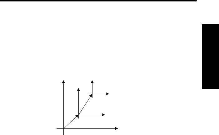
1.3.7Local coordinate system
When the system compiling programs in the workpiece coordinate system, sub-coordinate system of workpiece coordinate system can be set for easily programming, called local coordinate system as follows:
Local coordinate system |
Workpiece coordinate system |
Machine coordinate system |
Fig. 1-7 local coordinate system
1.3.8Interpolation function
Interpolation is defined as a planar or three dimensional contour formed by path of 2 or multiple axes moving at the same time, also called Contour control. The controlled moving axis is called link axis when the interpolation is executed. The moving distance, direction and speed of it are controlled synchronously in the course of running to form the required Composite motion path. Positioning control is defined that motion end point of one axis or multiple axes instead of the motion path in the course of running is controlled.
GSK988T has linear, arc and thread interpolation function.
Linear interpolation: Composite motion path of X, Z axis is a straight line from starting point to end point.
Circular interpolation: Composite motion path of X, Z axis is arc radius defined by R or the circle center (I, K) from starting point to end point.
Thread interpolation: Moving distance of X or Z axis or X and Z axis is defined by rotation angle of spindle to form spiral cutting path on the workpiece surface to realize the thread cutting. For thread interpolation, the feed axis rotates along with the spindle, the long axis moves one pitch when the spindle rotates one rev, and the short axis and the long axis directly interpolate.
Note 1:Xp, Yp, Zp are separately X or its parallel axis, Y or its parallel axis, Z or its parallel axis. The followings are the same as those.
Note 2: IP expresses the combination of X_Y_Z_(used in programming).
Programming
11
GSK988T Turning CNC System User Manual
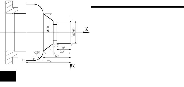
Example:
Programming
Fig.1-8
…
G32 W-27 F3 B→C thread interpolation G1 X50 Z-30 F100
G1 X80 Z-50 D→E linear interpolation G3 X100 W-10 R10 E→F arc interpolation
…
M30
1.4Coordinate Value and Dimension
1.4.1Absolute programming and incremental programming
The system has two methods to command the too traverse: absolute value and incremental value command. In the absolute programming, use the coordinate value programming of the end point; in the incremental programming, use the traverse distance programming. In the system, using the absolute programming or incremental programming is depended on the word of the command as follows:
Table 1- 4 a
|
Absolute value command |
Incremental value command |
X movement command |
X |
U |
|
|
|
Y movement command |
Y |
V |
Z movement command |
Z |
W |
C movement command |
C |
H |
|
|
|
A movement command |
A |
None |
|
|
|
B movement command |
B |
None |
|
|
|
The system can select the incremental programming or the absolute programming mode, or the incremental/absolute compound programming; the absolute command and the incremental command can be in the same block as follow:
X100.0 W100.0;
When the absolute command and the incremental command of one axis are in the same block, the following command value is valid.
12

Chapter Programming Fundamentals
The axis word can exist repetitively in the same block and the later value is valid, but when No.3403 Bit 6 (AD2) is set 1, the alarm occurs. U, W in other G command has bee specified to others. For example: in G73, the above conditions
1.4.2Diameter programming and radius programming
Because the workpiece section is the circle in CNC turning controlled program, X dimension can use two kind of method; diameter programming command and radius programming command.
1.The user can select the radius programming or diameter programming, which is set by state parameter (No. 1006 Bit 3(DIAX)).
2.Parameters related to diameter/radius programming:
State parameter No.1006 BIT3 (DIAx):
0—radius programming 1—diameter programming
State parameter No.5004 Bit1(ORC): 0—offset value is expressed with diameter; 1—offset value is expressed with radius;
Pay more attention to the conditions in the following table when X uses diameter programming: Table 1- 4 (b) related addresses and data to the diameter or radius programming
|
|
Word |
Explanation |
|
Diameter |
Radius |
|
|
|
|
|
|
|
programming |
programming |
|
|
|
X |
coordinate, |
polar |
Diameter |
Radius value |
|
|
X |
coordinate |
|
value |
|
|
|
|
G50 sets X coordinate |
Diameter |
Radius value |
|||
|
|
|
|||||
|
|
|
|
|
|
value |
|
|
|
|
X increment |
|
Diameter |
Radius value |
|
|
|
|
|
|
|
value |
|
|
|
U |
G71 infeed amount |
|
Radius value |
|
|
|
|
X |
finishing allowance in |
Parameter definition |
|||
|
|
|
G71, G72, G73 |
|
|
|
|
|
|
|
tool retraction |
|
Radius value |
|
|
Related |
|
|
amount in G73 |
|
|
|
|
addresses |
to |
|
Clearance in G71, G72 |
Radius value |
|
||
diameter/radius |
|
Clearance after cutting in |
Diameter |
Radius value |
|||
programming |
|
|
G75 |
|
value |
|
|
|
|
R |
Clearance to end point in |
Diameter |
Radius value |
||
|
|
G74 |
|
value |
|
||
|
|
|
Taper in G90, G92, G94, |
Radius value |
|
||
|
|
|
G76, radius in G02, G03, |
|
|
||
|
|
|
thread finishing amount in |
|
|
||
|
|
|
G76 |
|
|
|
|
|
|
I |
X amount of circle center |
Radius value |
|
||
|
|
|
G32,G34,G92,Pitch |
long |
Radius value |
|
|
|
|
F |
axis is X in G76 |
|
|
|
|
|
|
|
X feedrate display |
|
Radius/rev, radius /min |
||
|
|
|
|
|
|
|
|
Others |
|
X or U value of |
Display |
|
Diameter |
Radius value |
|
|
|
position |
|
|
|
value |
|
|
|
window |
|
|
|
|
|
Note: Besides the above-mentioned addresses and data related to the diameter programming or the radius programming, other related to word and data related to X numerical value are expressed with radius value.
Programming
13

Programming
GSK988T Turning CNC System User Manual
1.4.3Decimal programming
Value can be input by decimal programming. Distance, time and speed can be input by decimal programming. The following addresses can use decimal point: X, Y, Z, A, B, C, U, V, W, H, I, J, K, R and F, and other addresses cannot use decimal programming.
There are two types of decimal point usage which is decided by No. 3401 Bit0(DPI). When NO.3401 Bit 0(DPI) is set to 1, value without decimal point is with mm, inch. When NO.3401 Bit0(DPI) is set to 0, input value is specified by least input increment.
Parameter setting |
|
|
Least command unit |
||
ROTx=0 |
Rotary axis |
is |
ISC=0 ISC system |
0.001deg |
|
Rotary axis |
not related |
to |
|
|
|
ISC=1 ISB system |
0.0001deg |
||||
|
parameter INI |
||||
|
|
|
|||
|
|
|
|
|
|
ROTx=1 |
INI=0 |
|
ISC=0 ISC system |
0.001mm |
|
Linear axis |
Metric |
|
|
|
|
|
ISC=1 ISB system |
0.0001mm |
|||
|
|
|
|
|
|
|
INI=1 |
|
ISC=0 ISC system |
0.0001inch |
|
|
Inch |
|
|
|
|
|
|
ISC=1 ISB system |
0.00001inch |
||
|
|
|
|
|
|
Example: when the metric input, the least input increment unit are set to 0.001:
Program command |
The corresponding actual |
The corresponding actual value when |
|
value when DPI is 1 |
DPI is 0 |
|
|
|
X1000 without decimal |
1000mm |
1 mm |
command value |
Unit mm |
Unit: least input increment( set to 0.001) |
|
|
|
X1000.0 with decimal |
1000mm |
1000mm |
command value |
unit mm |
Unit mm |
|
|
|
The decimal which is less than the least input increment unit is discarded in course of program being executed.
Example: X2.34567. When the least unit of input increment is 0.001mm, X2.34567 becomes X2.345, when the least unit is 0.0001inch, it becomes X2.3456.
The system alarms when the specified is more than 8-digit value.
1.4.4Conversion between the metric and the inch
Metric input or inch input is set by NO.0000 Bit2(INI). G commands corresponding to metric/inch system is as follows:
G20 inch input
G21 mm input.
Input data unit becomes the inch or metric input unit when NO.0000 Bit2 (INI) setting is changed. But, the angle unit is not changed.
Input data unit becomes the inch or metric input unit when NO.0000 Bit2 (INI) setting is changed. But, the angle unit is not changed.
——F feedrate; ——position command;
——zero offset of workpiece; ——tool compensation value;
14
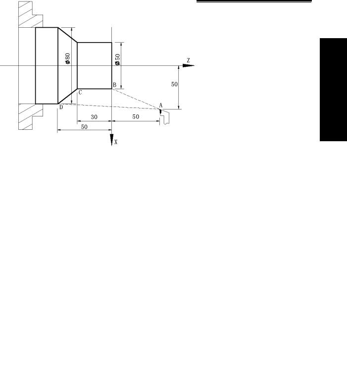
Chapter Programming Fundamentals
——graduation unit of MPG; ——movement distance in incremental feed.
NO.1001 Bit0 (INM) can set MM or INCH input of least command increment in linear axis. 0 mm input( metric machine)
1 inch input inch machine
1.4.5Linear axis and rotary axis
NO.1006 Bit0(ROTx) can set each axis to linear axis or rotary axis. NO. 1006 Bit 1 (ROSx) can be used to select the rotary type for each axis.
Absolute coordinate value is displayed circularly with the movement per rev set by NO.1260 when the cycle function is executed, which can prevent the rotary axis from overflowing. The cycle function is valid when NO.1008 Bit 0(ROAx) is set to 1.
For absolute value command, the coordinate values is the corresponding angle cycle value of per rev set by NO. 1260 after the machine moves. When NO.1008 Bit 1(RABx) is set to 0, the machine rotates according to the shortest distance(to the target point). For incremental command, the machine moves according to the angle defined by the command.
1.5Structure of an NC Program
User needs to compile part programs (called program) according to command formats of CNC system. CNC system executes programs to control the machine tool movement, the spindle starting/stopping, the cooling and the lubricant ON/OFF to complete the machine of workpiece.
Program example:
Programming
|
|
Fig. 1-9 |
O0001 |
; |
(Program name) |
N0005 |
G0 X100 Z50; |
(Rapidly positioning to A point) |
N0010 |
M12; |
(Clamping workpiece) |
N0015 |
T0101; |
(Changing No.1 tool and executing its offset) |
N0020 |
M3 S600; |
(Starting the spindle with 600 r/min) |
N0025 |
M8 |
(Cooling ON) |
N0030 |
G1 X50 Z0 F600; |
(Approaching B point with 600mm/min) |
15

GSK988T Turning CNC System User Manual
Programming
N0040 |
W-30 F200; |
(Cutting from B point to C point) |
N0050 |
X80 W-20 F150; |
(Cutting from C point to D point) |
N0060 |
G0 X100 Z50; |
(Rapidly retracting to A point) |
N0070 |
T0100; |
(Canceling the tool offset) |
N0080 |
M5 S0; |
(Stopping the spindle) |
N0090 |
M9; |
(Cooling OFF) |
N0100 |
M13; |
(Releasing workpiece) |
N0110 |
M30; |
(End of program, spindle stopping and Cooling OFF) |
The tool leaves the path of A→B→C→D→A after the above-mentioned programs are executed.
A program consists of a sequence of blocks, beginning with “OXXXX”(program name)and ending with “%”; a block begins with block number (omitted) and ends with “;” or “*”. See the general
structure of program as Fig. 1-10:
Program annotation
Program name
Block skip character |
Word |
 Block
Block
Block number
 Character for end of block
Character for end of block
Program
Fig. 1-10 Structure of a program
1.5.1Program name
Format: ○
Program number (0000 9999, the leading zero can be omitted Address O
is number of a program name, its range is 4-digit integer 0000 9999, the system alarms when the negative program name is input. The system ignores NC commands when program are edited and other NC commands are edited in the first line.
1.5.2Block format
1. Format: / N countless words;
/ skip character. A block can have or not it, generally, it is placed in the initial position of a program; user can press “SKIP” on the operation panel to execute the operation when the skip function is valid, otherwise, the “SKIP” key on the operation panel is valid, i.e. the skip character in the block is invalid;
N block number. A block can have or not it; number following N is 5-digit positive integer 00001 99999, and the system alarms when the input number is decimal.
16
 Loading...