


 This user manual describes all items concerning the operation of this CNC system in detail. However, it is impossible to give particular
descriptions for all unnecessary or unallowable operations due to length
limitation and products application conditions Therefore, the items not
presented herein should be considered impractical or unallowable.
 Copyright is reserved to GSK CNC Equipment Co., Ltd. It is illegal for any organization or individual to publish or reprint this manual. GSK CNC
Equipment Co., Ltd. reserves the right to ascertain their legal liability.

GSK25i Milling CNC System User Manual
Preface
Your Excellency,
We are honored by your purchase of this GSK 25i Milling CNC System made by GSK CNC Equipment Co., Ltd.
This book is “PARAMETER” section of the User Manual Volume .
Special caution:
The power supply fixed on/in the cabinet is exclusively used for the CNC system made by GSK.
It can't be applied to other purposes, or else it may cause serious danger.
II

Volume Parameter
Warning and Precaution
Accident may occur by improper connection and operation This system can only be operated by authorized and qualified personnel.
Please read this manual carefully before operation
Please read this manual and a manual from machine tool builder carefully before installation, programming and operation, and strictly observe the requirements.
This manual includes the precautions for protecting user and machine tool. The precautions are classified into Warning and Caution according to their bearing on safety, and supplementary information is described as Note. Read these Warnings, Cautions and Notes carefully before operation.
Warning
User may be injured or equipment be damaged if operation instructions and procedures are not observed.
Caution
Equipment may be damaged if operation instructions or procedures are not observed.
Note
It is used to indicate the supplementary information other than Warning and Caution.
III

GSK25i Milling CNC System User Manual
Announcement
●This manual describes various possibilities as much as possible. However, operations allowable or unallowable cannot be explained one by one due to so many possibilities that may involve with, so the contents that are not specially stated in this manual shall be considered as unallowable.
Caution
●Functions, technical indexes (such as precision and speed) described in this user manual are only for this system. Actual function deployment and technical performance of a machine tool with this CNC system are determined by machine tool builder’s design, so functions and technical indexes are subject to the user manual from machine tool builder.
●Refer to the user manual from machine tool builder for function and meaning of keys on control panel.
IV

Volume Parameter
Precautions
■Delivery and storage
●Packing box over 6 layers in pile is unallowed.
●Never climb the packing box, neither stand on it, nor place heavy objects on it.
●Do not move or drag the products by the cables connected to it.
●Forbid collision or scratch to the panel and display screen.
●Avoid dampness, insolation and drenching.
■Open-package inspection
●Confirm that the products are the required ones.
●Check that the products are not damaged in delivery.
●Confirm that the parts in packing box are in accordance with the packing list.
●Contact us in time if any inconsistence, shortage or damage is found.
■Connection
●Only qualified personnel can connect the system or check the connection.
●The system must be earthed, and the earth resistance must be less than 0.1Ω. The earth wire cannot be replaced by zero wire.
●The connection must be correct and firm to avoid any fault or unexpected consequence.
●Connect with surge diode in the specified direction to avoid damage to the system.
●Switch off power supply before plugging out or opening electric cabinet.
■Troubleshooting
●Only competent personnel are supposed to inspect the system or machine.
●Switch off power supply before troubleshooting or changing components.
●Check for fault when short circuit or overload occurs. Restart can only be done after troubleshooting.
●Frequent switching on/off of the power is forbidden, and the interval time should be at least 1 min.
V

GSK25i Milling CNC System User Manual
Safety Responsibility
Manufacturer’s Responsibility
——Be responsible for the danger which should be eliminated and/or controlled on design and configuration of the provided CNC systems and accessories.
——Be responsible for the safety of the provided CNC systems and accessories.
——Be responsible for the provided information and advice for the users.
User’s Responsibility
——Be trained with the safety operation of CNC system and familiar with the safety operation procedures.
——Be responsible for the dangers caused by adding, changing or altering to the original CNC systems and the accessories.
——Be responsible for the failure to observe the provisions for operation, adjustment, maintenance, installation and storage in the manual.
All specifications and designs herein are subject to change without further notice.
This manual is reserved by end user.
We are full of heartfelt gratitude to you for supporting us in the use of GSK’s products.
VI

Volume Parameter
Contents
1 PARAMETER DISPLAY .......................................................................................................................... |
1 |
|
2 PARAMETER SETTING IN THE MODE OF MDI......................................................................................... |
2 |
|
3 SETTING OR MAINTAINING THE SYSTEM PARAMETERS BY PC INSTRUCTION CONTROL UNIT SOFTWARE.. |
4 |
|
3.1 |
Editing of System Parameters ................................................................................................ |
4 |
3.2 |
Editing of Tool and Offset Parameter...................................................................................... |
5 |
3.3 |
Editing of the Pitch Error Compensation Data ........................................................................ |
6 |
3.4 |
Editing of PLC Parameter....................................................................................................... |
7 |
4 PARAMETER EXPLANATION ................................................................................................................. |
8 |
||
4.1 |
Parameter Setting (1 99)...................................................................................................... |
8 |
|
4.2 |
Communication Parameter (100 999) .................................................................................. |
9 |
|
4.3 |
Coordinate Parameter (1000 1199).................................................................................... |
11 |
|
4.4 |
Feedrate Parameter (1200 1399)....................................................................................... |
21 |
|
4.5 |
Interpolation and Acceleration/Deceleration Control Parameter (1400 1599) .................... |
24 |
|
4.6 |
Editing Parameter Display (1600 1799) ............................................................................. |
31 |
|
4.7 |
Programming Parameter (1800 1999) ............................................................................... |
35 |
|
4.8 |
Fixed Cycle Parameter (2000 2099) .................................................................................. |
39 |
|
4.9 |
Rigid Tapping Parameter (2100 2299) ............................................................................... |
40 |
|
4.10 |
Parameter of Manual, Auto and MPG Operation (2300 2499) ......................................... |
42 |
|
4.11 Parameter (2500 2599) Input/Output ............................................................................... |
43 |
||
4.12 Tool Administration Parameter (2600 2799)..................................................................... |
45 |
||
4.13 |
Pitch Compensation Parameter (2800 2999)................................................................... |
48 |
|
4.14 |
Servo Parameter (4000 4999) ......................................................................................... |
49 |
|
4.15 |
Spindle Control Parameter (5000 5999)........................................................................... |
61 |
|
4.16 |
Custom Macro Program Parameter (6000 6999)............................................................. |
65 |
|
4.17 |
System Diagnosis Configuration Parameter (9000 9999) ................................................ |
68 |
|
VII

GSK25i Milling CNC System User Manual
VIII

Volume Parameter
1 Parameter Display
The operations are shown below:
(1) Enter the parameter screen after the function key  on MDI panel is controlled for many times, or press the [Parameter] and [Operation] soft keys subsequently after pressing the function
key  once.
once.
Return to the manual |
Soft Keyboard |
|
|
|
Fig.1-1 |
Fig.1-2 Function keys
(2) The parameter screen consists of multiple pages. Use two steps to display the page that
contains the parameter you want to display.
(a) The required relative parameters are selected using the soft key, and then the page to be
1
GSK25i Milling CNC System User Manual
found by the page keys or cursor move keys.
(b) The parameter numbers to be displayed are input from keyboard, and press the [search]
softkey to search, then the specified parameter page is displayed, and the cursor is positioned to the
specified parameter (the data part is turned into the selected color).
2 Parameter Setting in the Mode of MDI
The operation steps of parameters setting are shown below:
(1) Enter the offset setting page by pressing the  , and firstly to input the correspondence password.
To prevent the machining program and CNC parameters from being maliciously modified, the GSK 25i offers an authority setting function and the password can be divided into 9 levels, from the higher to the lower level, such as the 0 level (the system high level), the 1st level (the system service), the 2nd level (the machine manufacturer), the 3rd level (the installation and debugging), the 4th level (the terminal administration), as well as the 5th level (the operator 1 level), the 6th level (the operator 2 level), the 7th level (the operator 3 level) and the lowest default level (see the figure 2-1). The 0 level is enjoys the highest protection; contrarily, the lowest levels are from 5 to 7, and the highest level can be administrated the lowest levels, which is the low authority function. The parameter password level is 3 except for the special explaination.
Fig. 2-1
2

Volume Parameter
Level 0: the highest authority, reserved by the developer.
Level 1: It is used for the system manufacturer service, which can modified various data.
Level 2: The PLC program, PLC note and the pitch error compensation are modified. The PLC and the pitch error compensation files are input or output. The user customized interface authority is modified/ input or output.
Level 3: The parameter and PLC source data can be modified; the PLC operation is started/stopped; the alarm/operation messages are eliminated; and the files are input or output, and the system, interpolation and positional control maintenance softwares can be upgraded.
Level 4: The program, tool offset, setting, workpiece coordinate system offset and macro program value are modified; these files are input or output and it also has the authority to modify the passward.
The 5th, 6th and 7th levels: it is an operation authorized to corresponding person with bit-parameter by the end user administrator.
The lowest level default by the system: it is an authority operation donated with bit-parameter by end user administrator; no password inputs.
The bit-parameter definitions are authorized by the end user administrator, refer to the following table:
Bit |
Significance |
Note |
0 |
Modify/input or output the authority of G code program. |
Authority |
1 |
Modify the authority of geometrical tool offset/input or output tool |
Authority |
|
offset. |
|
2 |
Modify the authority of wear tool offset/input or output tool offset. |
Authority |
3 |
Modify the authority of setting |
Authority |
4 |
Modify/input or output the authority of a workpiece coordinate |
Authority |
|
system offset. |
|
5 |
Modify/input or output the authority of a macro program value |
Authority |
6 |
Reserved |
|
7 |
Reserved |
|
(2)In the [MDI/Edit] mode, the MDI mode  and Edit mode
  can be selected, and the cursor can be moved based on the password authority to the required items.
(3)Press the  key, the corresponding level password can be input. If the password is correct, a “correct password” may be displayed in the system; otherwise a “wrong password input” may occur.
(4)After the corresponding parameters are modified, the password is cancelled after logging out.
3
GSK25i Milling CNC System User Manual
3 Setting or Maintaining the System Parameters by PC Instruction
Control Unit Software
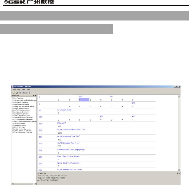
3.1 Editing of System Parameters
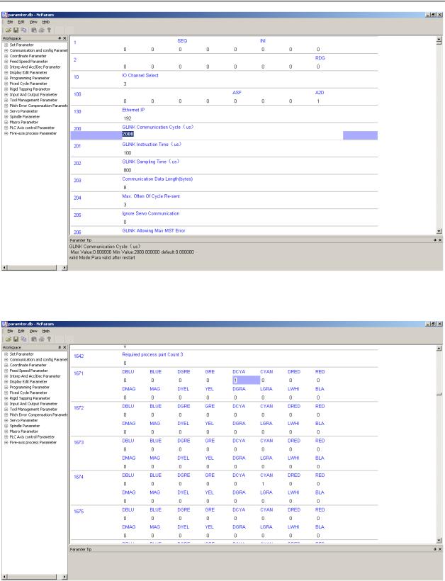
This software can be edited the system parameter on CNC in the program, and the corresponding backup parameter files can be uploaded and downloaded through the internet. (Refer to the Fig. 3-1, Fig. 3-2 and Fig. 3-3)
Fig.3-1 Editing the system parameters (Editing of the bit parameters)
4
Volume Parameter
Fig.3-2 Editing the system parameters II (Editing of data parameters)
Fig.3-3 Editing the system parameters III (Editing of color parameters)
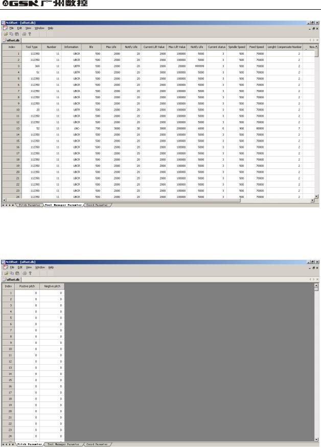
3.2 Editing of Tool and Offset Parameter
Editing of the tool and offset parameter is as the Fig. 3-4.
5
GSK25i Milling CNC System User Manual
Fig. 3-4 Editing of tool and offset parameter
3.3 Editing of the Pitch Error Compensation Data
Editing the pitch error compensation data is as Fig. 3-5.
Fig. 3-5 Editing of the pitch error compensation data
6
Volume Parameter
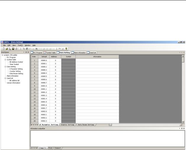
3.4Editing of PLC Parameter
Editing the PLC parameter is as Fig. 3-6.
Fig. 3-6 Editing of PLC parameter
7

GSK25i Milling CNC System User Manual
4 Parameter Explanation
[Parameter type]
The system parameters can be divided into several types based upon the following parameters (refer to the fig. 4-1).
Table 4-1 data type and data effective range
Data type |
Effective data range |
Bit |
0 or 1 |
Bit axis |
0 or 1 |
Integrated |
99999999 99999999 |
Integral axis |
99999999 99999999 |
Real number |
99999999 99999999 |
Real number axis |
99999999 99999999 |
The displayed number of axis type is determined on the total setting axis amount.
[Parameter explanation format]
The system parameter can be defined based on the following format.
Parameter number |
Parameter significance explanation |
It is important to notice that the cautions may occur in the notice column to remind the user
Note
1.Notice 1
2.Notice 2
3.Notice 3 4,……
4.1Parameter Setting (1 99)
7# |
6# |
5# |
4# |
3# |
2# |
1# |
0# |
|
|
|
|
|
|
|
|
|
|
0001 |
|
|
SEQ |
|
|
INI |
|
|
[Data type] Bit [Data range] 0 or 1
INI: Unit of input 0 In mm 1 In inches
SEQ: Automatic insertion of sequence numbers 0 Not performed
1 Performed
8

Volume Parameter
Note:
The incremental of sequence number is set in parameter No.1621.
[Standard setting] 0 0 0 0 |
0 0 0 0 |
|
|
|
|
|
|
|
|
|
|||||
|
|
|
|
7# |
6# |
5# |
|
4# |
3# |
2# |
1# |
0# |
|
||
|
|
|
|
|
|
|
|
|
|
|
|
|
|
|
|
|
|
0002 |
|
|
|
|
|
|
|
|
|
|
|
RDG |
|
[Data type] Bit |
|
|
|
|
|
|
|
|
|
|
|
|
|||
[Data range] 0 or 1 |
|
|
|
|
|
|
|
|
|
|
|
|
|||
RDG: Remote diagnosis is |
|
|
|
|
|
|
|
|
|
||||||
|
0 Not performed |
|
|
|
|
|
|
|
|
|
|
|
|||
|
1 Performed |
|
|
|
|
|
|
|
|
|
|
|
|||
[Standard setting] 0 0 0 0 0 0 0 0 |
|
|
|
|
|
|
|
|
|
||||||
|
|
|
|
|
|
|
|
|
|
||||||
|
0010 |
|
I/O CHANNEL selection |
|
|
|
|
|
3 |
|
|||||
[Data type] Integrated type
[Data range] 0-4 [Standard setting]
|
|
Setting value |
|
|
Significance |
|
|
|
|
|||||
|
|
0 |
|
|
|
|
RS232C serial port |
|
|
|
||||
|
|
1 |
|
|
|
|
|
Reserved |
|
|
|
|
||
|
|
2 |
|
|
|
|
|
Reserved |
|
|
|
|
||
|
|
3 |
|
|
|
|
USB interface |
|
|
|
||||
|
|
4 |
|
|
|
|
Ethernet interface |
|
|
|
||||
4.2 Communication Parameter (100 999) |
|
|
|
|
||||||||||
7# |
|
6# |
5# |
4# |
3# |
|
2# |
1# |
0# |
|
||||
|
|
|
|
|
|
|
|
|
|
|
|
|
||
|
0100 |
|
|
|
|
|
|
ASF |
|
|
|
A2D |
|
|
[Data type] Bit type |
|
|
|
|
|
|
|
|
|
|
||||
[Data range] 0 or 1 |
|
|
|
|
|
|
|
|
|
|
||||
A2D: DSP loading method |
|
|
|
|
|
|
|
|
|
|
||||
0 DSP directly start mode
1 Loading DSP using cnc program
ASF The current file of previous one is whether to save automatically while the file is loaded.
0 Yes |
|
1 No |
|
[Standard set] |
0 0 0 0 0 0 0 1 |
9

GSK25i Milling CNC System User Manual
0130 |
Ethernet IP address |
192 |
[Data type] Integrated type
[Data range] 0-255
Note
For example: The value of IP:192.168.2.10 is 10 (192.168.2 is a fixed value)
200 |
GSK-LINK communication period |
200000 |
[Data type] Integrated type
[Data unit] 10ns
[Data range] 10000 1000000(100us-10ms)
|
201 |
|
|
GSK-LINK command time |
10000 |
|
||
[Data type]Integrated type |
|
|
|
|
||||
[Data unit] 10ns |
|
|
|
|
||||
[Data range] 100 1000000 |
|
|
|
|
||||
|
|
|
|
|
|
|
|
|
|
202 |
|
|
GSK-LINK sampling time |
80000 |
|
||
[Data type]Integrated type |
|
|
|
|
||||
[Data unit] 10ns |
|
|
|
|
||||
[Data range] 100 1000000 |
|
|
|
|
||||
|
|
|
|
|
|
|
||
|
|
203 |
|
|
The length of period communication data |
|
8 |
|
[Data type] Integrated type |
|
|
|
|
||||
[Data unit] Byte |
|
|
|
|
||||
[Data range] 6 16 Required in multiples of 2 |
|
|
|
|||||
|
|
|
|
|
|
|||
|
|
204 |
|
|
The maximum period repeated times |
|
3 |
|
[Data type] Integrated type |
|
|
|
|
||||
[Data unit] |
|
|
|
|
||||
[Data range] 0 16 |
|
|
|
|
||||
|
|
|
|
|
|
|||
|
|
205 |
|
|
Servo communication ignorance |
|
0 |
|
[Data type] Integrated |
|
|
|
|
||||
[Dtat unit]
[Data range] 0 1
10

Volume Parameter
Note:
The system may ignore the servo net communication when it is set to 1, which is mainly used for debugging; when this parameter is set, the power must be turned off before operation is continued.
4.3 Coordinate Parameter (1000 1199)
7# |
6# |
5# |
4# |
3# |
2# |
1# |
0# |
||
|
|
|
|
|
|
|
|
|
|
1000 |
|
|
|
|
|
|
|
ISC |
INM |
[Data type] Bit |
|
|
|
|
|
|
|
|
|
[Data range] |
0 or 1 |
|
|
|
|
|
|
||
INM: Least command increment on the linear axis 0 In mm (Metric system)
1 In inches (Inch system) ISC The least move unit
0 0.001mm, 0.001deg
1 0.0001mm, 0.0001deg
Note:
When this parameter is set, the power must be turned off before operation is continued.
[Standard setting] |
0 0 0 0 |
0 0 1 0 |
|
|
|
|
|
|
|||
|
|
7# |
6# |
|
5# |
4# |
3# |
2# |
1# |
0# |
|
|
|
|
|
|
|
|
|
|
|
|
|
|
1001 |
|
|
|
|
|
|
|
SFD |
DLZ |
|
[Data type] Bit |
|
|
|
|
|
|
|
|
|
|
|
[Data range] 0 or 1 |
|
|
|
|
|
|
|
|
|
|
|
DLZ: Function setting the reference position without dog |
|
|
|
||||||||
0 Disabled |
|
|
|
|
|
|
|
|
|
|
|
1 Enabled |
|
|
|
|
|
|
|
|
|
|
|
SFD: The function for shifting the reference position is |
|
|
|
||||||||
0 Not used |
|
|
|
|
|
|
|
|
|
|
|
1 Used |
|
|
|
|
|
|
|
|
|
|
|
[Standard setting] |
0 0 0 0 |
0 0 0 0 |
|
|
|
|
|
|
|||
11
GSK25i Milling CNC System User Manual
7# |
6# |
5# |
4# |
3# |
2# |
1# |
0# |
|
|
|
|
|
|
|
|
|
|
1002 |
|
|
EDN |
EDP |
HJZ |
|
|
|
[Data type] Bit [Data range] 0 or 1
HJZ: When a reference position is already set:
0:Manual reference position return is performed with deceleration dogs.
1:Manual reference position return is performed using rapid traverse without deceleration dogs.
EDP: External deceleration signal in the positive direction for each axis
0:Valid only for the rapid traverse
1:Valid for rapid traverse and cutting feed
EDN: External deceleration signal in the negative direction for each axis
0:Valid only for rapid traverse
1:Valid for rapid traverse and cutting feed
[Standard setting] 0 0 0 0 1 0 0 0
7# |
6# |
5# |
4# |
3# |
2# |
1# |
0# |
|
|
|
|
|
|
|
|
|
|
1004 |
|
|
ZMIX |
|
|
RRLn |
|
|
[Data type] Bit axis [Data range] 0 or 1
RRLn: Relative coordinates are
0:Not rounded by the amount of the shift per one rotation
1:Rounded by the amount of the shift per one rotation ZMIx: Reference position return direction is set for each axis
0:In positive
1:In negative
Note:
When this parameter is set, the power must be turned off before operation is continued.
[Standard setting] 0 0 0 0 0 0 0 0
1020 Program axis name for each axis
[Data type] Integrated axis
[Data range] 0 127
Note
The display name is ASCII code, and the allowable input values are
X-88, Y-89, Z-90, A-65, B-66 and C-67.
12

Volume Parameter
1021 The attribute of each axis in the basic coordinate system
[Data type] Integrated [Data range] 0 7
Setting value |
Significance |
0 |
Neither the basic three axes nor a parallel axis |
1 |
X axis of the basic three axes |
2 |
Y axis of the basic three axes |
3 |
Z axis of the basic three axes |
4 |
Axis parallel to the X axis |
5 |
Axis parallel to the Y axis |
6 |
Axis parallel to the Z axis |
1022 Servo logic address for each axis
[Data type] Integrated [Data range] 0 25
Note
The setting of servo logic address is related to the connection of servo network, the 1st slave station connected from the system P1 terminal is 0, according to this, servo logic address is its corresponding set value; Usually, set a same value both the control axis number and the controlled axis number.
7# |
6# |
5# |
4# |
3# |
2# |
1# |
0# |
|
|
|
|
|
|
|
|
|
|
1023 |
|
|
|
|
|
|
ISRn |
AXUn |
[Data type] Bit axis [Data range] 0 or 1
AXUn: Enabling for each axis is
0:Not used
1:Used
ISRn: It is either rotation axis or pallel axis for each axis
0:Pallel axis
1:Rotation axis
[Standard setting] 0 0 0 0 0 0 0 1
|
7# |
6# |
5# |
4# |
3# |
2# |
1# |
0# |
|
|
|
|
|
|
|
|
|
1030 |
ITI |
IDX |
|
|
|
ABS |
REL |
RMOD |
[Data type] Bit [Data range] 0 or 1
RMOD: G code rotation command movement method
0: The approximate principle moves to the nearest position
13

GSK25i Milling CNC System User Manual
1: Value magnitude moves
REL: Relative coordinate display of rotation axis
0:Out of the 360°
1:Within 360°
ABS: Absolute coordinate display of rotation axis
0:Out of the 360°
1:Within 360°
IDX: Index table indexing sequence.
0:Type A
1:Type B
ITI: The index function of the index table is:
0:Disabled
1:Enabled
[Standard setting] 0 |
0 0 0 |
0 0 0 0 |
|
|
|
|
|
|
|||
|
|
7# |
6# |
5# |
4# |
3# |
2# |
1# |
0# |
||
|
|
|
|
|
|
|
|
|
|
|
|
|
1031 |
|
|
|
|
|
G52 |
RLC |
|
|
|
[Data type] Bit |
|
|
|
|
|
|
|
|
|
|
|
[Data range] 0 or 1 |
|
|
|
|
|
|
|
|
|
|
|
RLC: Local coordinate system is |
|
|
|
|
|
|
|||||
0:Not cancelled by reset
1:Cancelled by reset
G52: In local coordinate system setting, a cutter compensation vector is
0:Not considered
1:Considered
[Standard setting] |
0 0 0 0 1 0 0 0 |
|
||
|
|
|
|
|
|
1040 |
|
External workpiece origin offset value |
0 |
[Data type] Real number axis
[Data unit] mm
[Data range] -9999.9999 9999.9999
1041 |
The origin offset amount of workpiece |
0 |
|
coordinate system 1(G54) |
|
[Data type] Real number axis
[Data unit] mm
[Data range] -9999.9999 9999.9999
14

Volume Parameter
1042 |
The origin offset amount of workpiece |
0 |
|
coordinate system 2(G55) |
|
[Data type] Real number axis
[Data unit] mm
[Data range] -9999.9999 9999.9999
1043 |
The origin offset amount of workpiece |
0 |
|
coordinate system 3(G56) |
|
[Data type] Real number axis
[Data unit] mm
[Data range] -9999.9999 9999.9999
1044 |
The origin offset amount of workpiece |
0 |
|
coordinate system 4(G57) |
|
[Data type] Real number axis
[Data unit] mm
[Data range] -9999.9999 9999.9999
1045 |
The origin offset amount of workpiece coordinate |
0 |
|
system 5(G58) |
|
[Data type] Real number axis
[Data unit] mm
[Data range] -9999.9999 9999.9999
1046 |
The origin offset amount of workpiece coordinate |
0 |
|
system 6(G59) |
|
[Data type] Real number axis
[Data unit] mm
[Data range] -9999.9999 9999.9999
1050 |
Coordinate value of the 1st reference position on |
0 |
|
each axis in the mechanical coordinate system |
|
[Data type] Real number axis
[Data unit] mm
[Data range] -9999.9999 9999.9999
Note:
When this parameter is set, the power must be turned off before operation is continued.
15
 Loading...