


GSK980T
Turning Machine CNC System
User Manual

GSK980T CNC SYSTEM USER MANUAL
INTRODUCTION······························································································································1
1.1Introduction································································································································· 1
1.2Type Signification························································································································ 1
1.3Type Table ··································································································································· 1
II. Programming ······································································································································2
2.1General······································································································································ 2
2.1.1Axes Definition ·················································································································· 2
2.1.2Reference Point (Machine Zero Point) ··············································································· 2
2.1.3Coordinate value and direction and dimension··································································· 2
2.1.4Unit and Range of coordinate····························································································· 3
2.1.5Initial and Modal Status of the Command ·········································································· 3
2.1.6The Start of a Program········································································································ 3
2.1.7The End of a Program········································································································· 3
2.1.8Program Configuration······································································································· 3
2.1.9Program Configuration······································································································· 3
2.2controlled Axis·························································································································· 5
2.2.1Number of Controlled Axis ································································································ 5
2.2.2Unit Setting ························································································································ 5
2.2.3Maximum Strokes ·············································································································· 5
2.3Preparatory Function (G Function)···························································································· 6
2.3.1Positioning(G00) ················································································································ 7
2.3.2Linear Interpolation (G01)·································································································· 7
2.3.3Circular Interpolation (G02,G03) ······················································································· 8
2.3.4Thread Cutting (G32) ······································································································· 11
2.3.5Return to Reference Point Automatically (G28) ······························································· 14
2.3.6Dwell(G04) ······················································································································ 14
2.3.7Work Coordinate System Setting(G0) ·············································································· 14
2.3.8Feed per Minute (G98) ····································································································· 15
2.3.9Feed per Revolution(G99)································································································ 15
2.3.10Constant Surface Speed Control(G96, G97)··································································· 17
2.3.11Canned Cycle(G90, G92 G94)························································································ 20
2.3.12Multiple Repetitive Cycle (G70~G75) ··········································································· 25
2.3.13Notes on Multiple Repetitive Cutting Cycle (G70~G75)················································ 34
2.4Spindle Function(S Function)·································································································· 34
2.4.1Spindle Speed Command·································································································· 34
2.5Tool Function·························································································································· 35
2.5.1Procedures of tool Change································································································ 35
2.5.2Tool selection (Change) Related Parameters ···································································· 36
2.6Auxiliary Function(M function) ······························································································ 36
2.6.1Description of M F unction ······························································································ 37
2.6.2M function Related Data··································································································· 37
2.7Program Configuration············································································································ 39
2.7.1Program···························································································································· 39
2.7.2Program Number ·············································································································· 41
GUANGZHOU CNC EQUIPMENT CO., LTD.

GSK980T CNC SYSTEM USER MANUAL
2.7.3Sequence Number and Block···························································································· 42
2.7.4Word and Address ············································································································ 42
2.7.5Basic Addresses and Ranges of Command Values···························································· 43
2.7.6End of Program ················································································································ 43
2.8Coordinate Values and Dimensions························································································· 43
2.8.1Absolute Commands and Incremental Commands ··························································· 43
2.8.2Decimal Point Programming ···························································································· 45
2.8.3Diameter Designation and Radius Designation ································································ 45
2.9Tool Offset ······························································································································ 46
2.9.1Geometry Tool Offset······································································································· 46
2.9.2T Code for Tool offset ······································································································ 46
2.9.3Tool Offset Value Input by Moving the Tool To a Fixed Point ········································· 47
2.9.4Direct Input of Tool Offset by Trial Cutting ····································································· 47
2.10Automatic Acceleration and Deceleration ············································································· 49
2.10.1Speed Control In the Corner Between Blocks ··································································· 50
2.11The Macro Program to User ·································································································· 50
2.11.1The Macro Command········································································································ 51
2.11.2The Macro Program Body ······························································································ 51
2.11.3Operation and Transfer Dictate G65 ··········································································· 52
2.11.4The Note about the Macro Program Body ······································································ 54
2.11.5Example for User··············································································································· 55
III. Operation ·········································································································································56
3.1Operation Panel······················································································································· 56
3.1.1LCD/MDI Panel ··············································································································· 56
3.1.2Screen Change Keys········································································································· 57
3.1.3Explanation of Key Board ································································································ 57
3.1.4Machine Operation Panel ································································································· 58
3.2Manual Operation···················································································································· 59
3.2.1Manual Reference Point Return························································································ 59
3.2.2Manual start Point Return································································································· 59
3.2.3Manual Continuous Feed·································································································· 60
3.2.4Step Feed·························································································································· 61
3.2.5Manual Handle Feed (Optional function) ········································································· 62
3.2.6Manual auxiliary operation······························································································· 62
3.3Automatic Operation ··············································································································· 64
3.3.1Automatic Operation mode ······························································································ 64
3.3.2Starting Automatic Operation ··························································································· 65
3.3.3Executing Automatic Operation ······················································································· 65
3.3.4Stopping and Terminating Memory Operation ································································· 65
3.4TEST OPERATION················································································································ 67
3.4.1All Axis Machine Lock ···································································································· 67
3.4.2Auxiliary Function Lock ·································································································· 67
3.4.3Feedrate Override············································································································· 67
3.4.4Rapid Traverse Override··································································································· 68
3.4.5Dry Running····················································································································· 68
3.4.6Restart After Feed Hold···································································································· 68
GUANGZHOU CNC EQUIPMENT CO., LTD.

GSK980T CNC SYSTEM USER MANUAL
3.4.7Single Block ····················································································································· 68
3.5Safety Operation······················································································································ 69
3.5.1Emergency Operation······································································································· 69
3.5.2Overtravel························································································································· 70
3.6Alarm ······································································································································ 70
3.7Program Storage Edit ······································································································· 70
3.7.1Preparation for Part Program Storage Edit Operation ················································ 70
3.7.2Registering Program to Memory ······················································································ 70
3.7.3Program Number Searching ····························································································· 71
3.7.4Deleting Program ············································································································· 71
3.7.5Deleting All Program········································································································ 71
3.7.6Output a program ············································································································· 72
3.7.7Output All Programs········································································································· 72
3.7.8Sequence Number Search································································································· 72
3.7.9Inserting, Amending and Deleting of word······································································· 73
3.7.10Number of Registered Programs····················································································· 76
3.7.11Capacity of System Memory ·························································································· 76
3.8Display and Setting Data········································································································· 76
3.8.1Offset Amount ·················································································································· 76
3.8.2The setting of setting parameter························································································ 77
3.8.3The Setting and Display of Custom Macro Variable························································· 79
3.8.4Parameter ························································································································· 80
3.8.5Diagnoses ························································································································· 82
3.9Display ···································································································································· 82
3.9.1Status display···················································································································· 82
3.9.2Display of key in data······································································································· 83
3.9.3Program Number, Sequence Number Display ·································································· 83
3.9.4The Display of Program Memory Used.··········································································· 84
3.9.5Display of Command Value ([PRG] key) ········································································· 84
3.9.6Current position display ([POS] key) ··············································································· 85
3.9.7Display of Run Time and Parts Count ·············································································· 86
3.9.8Alarm Display([ALM] key)······························································································ 86
3.9.9Adjusting Brightness of LCD ··························································································· 87
IV CONNECTION ·································································································································88
4.1SYSTEM CONNECTION DIAGRAM··················································································· 88
4.1.1Layout diagram of interfaces···························································································· 88
4.1.2Descriptions of Interfaces································································································· 88
4.1.3Connection Diagram········································································································· 89
4.2Detail of connection ················································································································ 89
4.2.1From CNC to Axis Driver ································································································ 89
4.2.2Description of Signal········································································································ 90
4.3Connection between CNC and Axis Driver············································································· 92
4.4Spindle Encoder ······················································································································ 93
4.5RS232-C Serial Interface(Optional) ························································································ 93
GUANGZHOU CNC EQUIPMENT CO., LTD.

GSK980T CNC SYSTEM USER MANUAL
4-6 Spindle Analogue Control Interface(Optional) ······································································· 94
4-7 Handwheel ······························································································································ 94
4.8Connection of power supply···································································································· 95
4.9In put/output Interface············································································································· 96
4.9.1Connecting Diagram········································································································· 96
4.9.2Input Signals····················································································································· 96
4.9.3Signal Description ············································································································ 97
4.9.4Output Signal ················································································································· 100
4.9.5Diagnose Address Table of Input and Output Signal ······················································ 101
V Adjustment of Machine ····················································································································102
5.1Preparation before Power On ································································································ 102
5.2Adjustment of Machine ········································································································· 102
5.2.1Emergency Stop Button·································································································· 102
5.2.2Adjustment of Drive Axis······························································································· 102
5.2.3Toolpost Adjustment······································································································· 104
5.2.4Spindle Adjustment ········································································································ 104
5.2.5Single step/ Handle Feed ································································································ 104
5.2.6Others Adjustment·········································································································· 104
5.3Standard Parameter Setting and the Storage of Parameter, Diagnosis and Program ·············· 105
Appendix Parameter ·····················································································································106
Appendix II Diagnosis ·························································································································114 Appendix III Alarm Code List ·············································································································119 Appendix IV Binary to Decimal Conversion Table·············································································122 Appendix V Installation dimension ········································································································· I
GUANGZHOU CNC EQUIPMENT CO., LTD.

GSK980T CNC SYSTEM USER MANUAL
INTRODUCTION
1.1 Introduction
GSK980T is a well-pervading machine numerical-controlled system produced by my factory. As a upgrading production of the economical CNC,GSK980T has following characteristic:
Adopting 16-bit CPU,CPLD and hardware interpolation to realize high-speed and um level control
Adopting 4-layer PCB and having high integration, reasonable technology and high reliability
Having Chinese display with LCD and friendly interface, convenient operation
Being able to adjusting accelerating or decelerating speed, matching stepmotor or servo motor
Being able to adjust the ratio of electronic gear and having convenient application
1.2Type Signification
GSK 980T 
 —
—
Assembly form none small panel 420×260mm
|
|
|
L big panel 420×320mm |
|
|
|
B boxed assembly |
|
|
Sort symbol none surface operation panel |
|
|
|
|
A alloy-solid operation panel |
|
|
Machine CNC of 980T series |
|
|
|
Production symbol of GSK |
|
1.3 Type Table |
|
|
|
|
|
|
|
|
Order type |
|
specification |
|
|
|
|
|
GSK980T |
420×260mm |
surface operation panel |
|
GSK980T-L |
420×320mm |
surface operation panel |
|
GSK980T-B |
GSK980T-L |
|
|
|
boxed assembly line goes out from the hole |
|
|
|
of box bottom line going out from the top of box must be |
|
|
|
specified |
|
|
GSK980TA |
420×260mm |
alloy-solid operation panel |
|
GSK980TA-L |
GSK980TA |
being assembled with the additional panel of |
|
AP01 the size is 420×320mm |
||
|
|
||
|
GSK980TA-B |
GSK980TA-L |
boxed assembly |
|
GSK980T-DF3A □ □ □ |
Being assembled with DF3A with line going out from the |
|
|
□ |
bottom of box from the bottom of box |
|
GUANGZHOU CNC EQUIPMENT CO., LTD.
1
GSK980T CNC SYSTEM USER MANUAL
|
|
|
|
|
GSK980T-DF3A □ □ □ |
Being assembled with DF3A with line going out from back |
|
|
□-B |
from aerial socket in the back of box |
|
|
GSK980T-DY3 □ □ □ □ |
Being assembled with DY3 with line going out from back from |
|
|
-B |
aerial socket in the back of box |
|
|
GSK980T-DY3□□□□ |
Being assembled with DY3 with line going out from the bottom |
|
|
of box from the bottom of box |
|
|
|
|
|
Note “□□□□”is 4-bit digit. the first 2-bit means the specification of driver in X axis, the second 2-bit means the specification of driver in Z axis. “00” means no driver being assembled in that axis.
II. Programming
2.1General
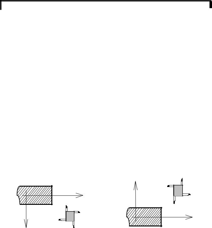
2.1.1Axes Definition
In this CNC system, the main two axis of motion of the lathe machine is referred to as X and Z axis in a right hand coordinate system. Since the spindle of the lathe is horizontal, the Z axis is horizontal as well, the cross axis is denoted by X.A positive motion in both X and Z direction moves the tool away from the workpiece.
The figure below shows the coordinate system of front toolpost lathe system and rear toolpost lathe system. In the front toolpost system, a positive command moves the Z axis from left to right and the X axis from back to front. In this CNC system we use front toolpost system for introducing the
programming. |
|
|
Front toolpost system |
|
Rear toolpost system |
|
Z |
X |
|
|
X |
Z |
2.1.2Reference Point (Machine Zero Point)
Reference point is a fixed position on a machine tool which the tool can easily be moved. Usually, the reference point is set at the max. travel position of each axis at positive direction. Don’t use the reference point return function (such as G28).if the reference point is not available on the corresponding machine tool.
2.1.3Coordinate value and direction and dimension
In this system, there are two ways to command the travels of the tool, the absolute command and incremental command, the using of the absolute command and the incremental command depending
GUANGZHOU CNC EQUIPMENT CO., LTD.
2

GSK980T CNC SYSTEM USER MANUAL
on the address used. Absolute and incremental commands can be used together in one block. The format of the address is as follows:
|
Address |
|
|
Absolute command |
Incremental command |
X axis |
X |
U |
Z axis |
Z |
W |
2.1.4Unit and Range of coordinate
The least input of this system is 0.001mm and the maximum input is ±9999.99.
Axis |
Least input unit |
Least motion increment |
X axis |
0.001mm(Diameter program) |
0.0005mm |
|
0.001mm(Radius program) |
0.001mm |
Z axis |
0.001mm |
0.001mm |
2.1.5Initial and Modal Status of the Command
Initial status is the status of the control before it is programmed. Modal status means after the command is specified; it is effective until another command in the same group is specified .
2.1.6The Start of a Program
At the beginning of program executing, the tool tips of the first programmed tool(standard tool)should be the start point of the programmed workpiece coordinate system. Usually, the first programmed tool is used as a standard tool which its offset compensation value is (0,0).
2.1.7The End of a Program
Command code M30 is specified in the last block of a program to end the executing of a program. Before ending the executing of grogram by M30, the tool must be programmed to return to the start point of the workpiece coordinate system, and the corresponding tool offset compensation must be cancelled.
2.1.8Program Configuration
The definition of the work coordinate system is depending on the start point of the tool in the corresponding work program by specifying a value after G50 is a floating coordinate, if G50 is not commanded the current absolute coordinate value is treated as the start point of the program.
After a workpiece coordinate system is set, a point on the tool, such as the tool tip, is at specified coordinate.
2.1.9Program Configuration
(1)Bock
The configuration of one block of program in this system is designated as follows:
N O O O O G O O X O O .O Z O O . O M O O S O O T O O O
CR
N: Sequence Number
GUANGZHOU CNC EQUIPMENT CO., LTD.
3
GSK980T CNC SYSTEM USER MANUAL
G: Preparatory Function
X,Z: Dimension word
M: Miscellaneous function
S:spindle function
T:Tool function CR: End of block
Each block of a program contains a sequence number for discriminating the executed sequence of each block the beginning of the block , and an end of bock code CR for indicating the end of the block..
(2)Program
Normally, a program number is specified at the beginning of the program, and a program end code M30 is specified at the end of the program.
CR:
00000: Program number
Block Block Block
M30CR |
End of program |
|
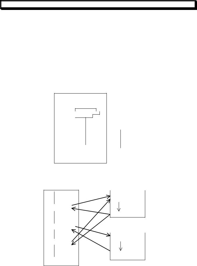
(3) Main Program and Subprogram
|
Subprogram |
#1 |
|
01001; |
Program for |
|
|
|
M98p1001 |
M99 |
pattern #1 |
|
|
|
M98P1002 |
Subprogram |
#2 |
M98p1001 |
01002; |
Program for |
|
|
|
|
|
pattern #2 |
|
M99 |
|
GUANGZHOU CNC EQUIPMENT CO., LTD.
4

GSK980T CNC SYSTEM USER MANUAL
When machining of the same pattern appears at many sections of a workpiece program, a program for this pattern is created first, this is called the subprogram, on the other hand, the original program is called the main program. When a subprogram execution command is executed during the executing of the main program, commands of the subprogram are executed. When the executing of the subprogram is finished, the sequence returns to the main program.
2.2controlled Axis
2.2.1 Number of Controlled Axis
|
Number of Controlled Axis |
|
2 Axis (X, Z) |
|
||
|
|
|
|
|
|
|
|
Number of Simultaneously control axis |
|
2 Axis (X, Z) |
|
||
|
|
|
|
|
|
|
2.2.2 Unit Setting |
|
|
|
|
||
|
|
|
|
|||
|
Input /Output |
The least input unit |
The least Command unit |
|||
|
|
X:0.001mm (Diameter designation) |
X:0.0005mm |
|||
Metric input /output |
Z:0.001 mm |
Z:0.001mm |
||||
X:0.001mm (Radius designation ) |
X:0.001mm |
|||||
|
|
|||||
|
|
Z:0.001 mm |
Z:0.001mm |
|||
When radius Program is designated, the movement on X axis is program in Radius. Refer to the Operation manual issued by the machine builder for detail.
2.2.3Maximum Strokes
Maximum Stroke = The least setting unit × 9999999
GUANGZHOU CNC EQUIPMENT CO., LTD.
5
GSK980T CNC SYSTEM USER MANUAL
2.3Preparatory Function (G Function)
A two-digit number following address G determines the meaning of the command for the concerned block. G codes are divided into the following two types:
Type |
|
Meaning |
|
||
One-shot G code |
|
The G code is effective only in the block in which it is specified |
|||
Modal G code |
|
The G code is effective until another G code in the same group is specified |
|||
(Example) G01 and G00 are modal G code in the same group |
|||||
|
G01X_; |
|
|
||
|
Z_; |
G01 is effective |
|||
|
G00Z_ ; |
G00 is effective |
|||
|
|
|
|
|
G Code List |
|
G Code |
|
Group |
Function |
|
|
G00 |
|
|
|
Positioning (Rapid traverse) |
|
*G01 |
|
|
01 |
Linear interpolation (Cutting feed) |
|
G02 |
|
|
Circular interpolation CW |
|
|
|
|
|||
|
G03 |
|
|
|
|
|
|
|
|
Circular interpolation CCW |
|
|
G04 |
|
|
00 |
Dwell, exactly stop |
|
G28 |
|
|
00 |
Return to reference point (Machine zero point) |
|
G32 |
|
|
01 |
Thread cutting |
|
G50 |
|
|
00 |
Coordination system setting |
|
G65 |
|
|
00 |
Macro command |
|
G70 |
|
|
|
Finishing cutting cycle |
|
G71 |
|
|
|
Outer diameter coarse cutting cycle |
|
G72 |
|
|
00 |
End face peck drilling cycle |
|
G73 |
|
|
Pattern repeating |
|
|
|
|
|||
|
G74 |
|
|
|
End face peck drilling cycle |
|
G75 |
|
|
|
Outer diameter/internal diameter slot cutting cycle |
|
G90 |
|
|
01 |
Outer diameter/internal diameter slot cutting cycle |
|
G92 |
|
|
Thread cutting cycle |
|
|
G94 |
|
|
|
End face cutting cycle |
|
G96 |
|
|
02 |
Constant surface speed control enable |
|
G97 |
|
|
Constant surface speed control disable |
|
|
|
|
|||
|
*G98 |
|
|
03 |
Feed per minute |
|
G99 |
|
|
Feed per revolution |
|
|
|
|
|||
Note1: G codes marked with*are initial G codes when turning on power.
Note2: The G codes of 2:00 are one-shot G codes.
Note3: when a G code which is not listed in this G codes list or a G code without a corresponding option function is specified, alarm (No.010) is displayed.
Note4: G codes of different groups can be specified in the same block of the program. If G codes of the same groups are specified in the same block, the last specified one is effective.
Note5: The maximum spindle speed can be specified by G50 under the constant line speed control.
Note6: G codes are displayed by each group number.
GUANGZHOU CNC EQUIPMENT CO., LTD.
6

GSK980T CNC SYSTEM USER MANUAL
Note7: The clock wise or counterclockwise of G02,G03 commands are defined by the direction of the coordination system.
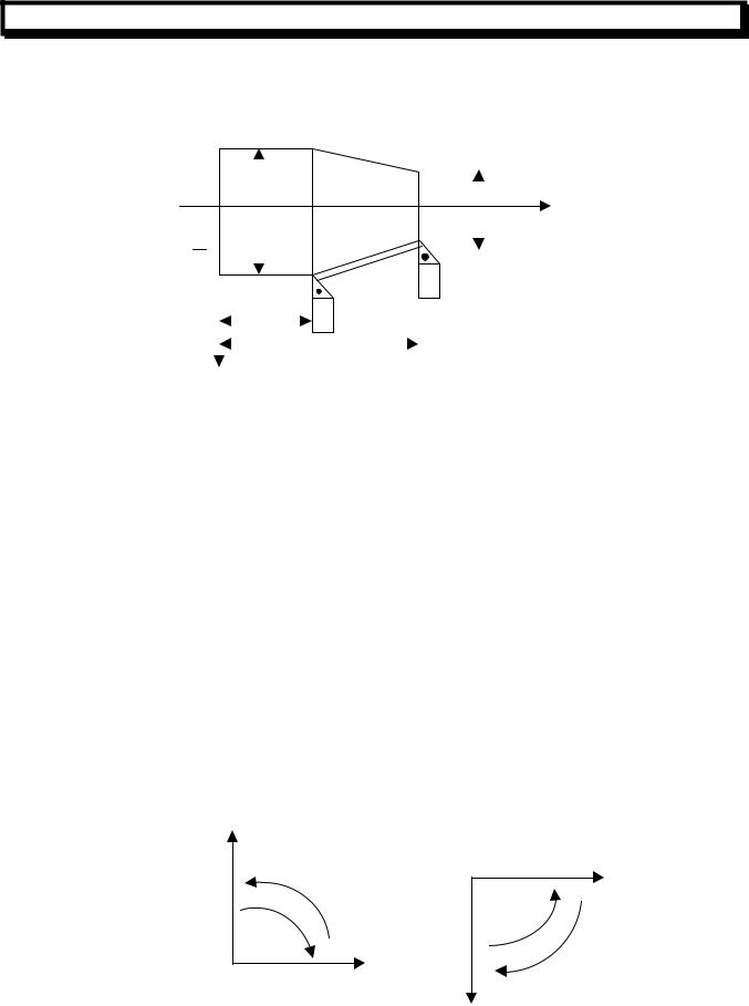
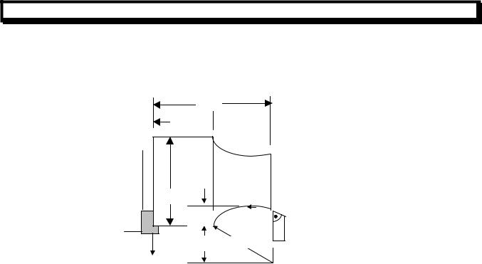
2.3.1Positioning(G00)
The G00 command moves the tool to the specified position at a rapid traverse rate. Format:G00X((U)__Z(W)__;
The tool is positioned with the rapid traverse rate for each axis separately.
|
Z |
X |
(Diameter programming) |
X |
|
X |
|
Non linear interpolation positioning
(Example)
|
|
Z |
|
φ40.0 |
G00 U-60.0 W-36.0; |
|
G00 X40.0 Z56.0;or |
|
|
|
|
|
|
(Diameter programming) |
56.0 |
|
30.0 |
|
|
|
|
|
36.0 |
Note: the Rapid traverse speed of the G00 command is set by the machine builder (ParameterNo.022~023),
The rapid traverse feed rate for each axis of G00 command depends on the machine builder’s setting (Parameter No.022~023),it is controlled by Rapid traverse feed rate override switch on the operation panel. (F0,25%,50%,100%),rapid traverse can not be specified by F code.
2.3.2Linear Interpolation (G01)
G01X (U) __Z (W) __F__;
GUANGZHOU CNC EQUIPMENT CO., LTD.
7
GSK980T CNC SYSTEM USER MANUAL
This command specified a linear interpolation movement. Absolute or incremental dimension depends on the address X, Z/U, W .The feedrate is specified by address F, and is effective until a new value is specified .The feedrate need not be specified every time.
(Example)
|
|
|
|
|
|
|
|
|
|
|
|
|
|
|
|
|
|
|
|
|
|
|
|
|
|
|
|
|
|
|
|
|
|
|
|
|
|
|
|
||
|
|
|
|
|
|
Start Point |
φ20.0 |
|
|||||
|
|
φ40.0 |
|
||||||||||
|
|
|
|
|
|
|
|||||||
|
|
|
|
|
|
|
End point |
|
|
|
G00 |
U20.0 W-26.0; |
|
|
|
|
|
|
|
|
|
|
|
||||
|
|
|
|
|
|
|
|
|
|
||||
|
|
|
|
|
|
|
|
|
|||||
|
|
|
|
|
|
|
|
|
|||||
|
|
|
|
|
|
|
|
|
|
|
|
||
|
|
|
20.0 |
|
|
|
|
|
|
|
G01 |
X40.0 Z20.0;or |
|
|
|
|
|
|
|
||||||||
|
|
|
|
|
|
46.0 |
|
|
|
|
|
Diameter Programming |
|
|
|
|
|
|
|
|
|||||||
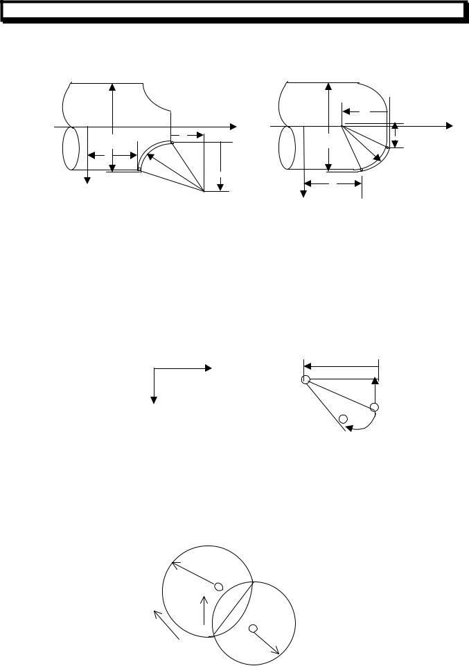
2.3.3Circular Interpolation (G02,G03)
The command below can move the tool along a circular arc on the specified plane. G02 X__Z__ R_F
G03 X__Z__ I_K_F
Command |
Description |
|
G02 |
|
Clockwise direction(CW) |
G03 |
|
Counterclockwise direction(CCW) |
|
Z |
The end point of the arc in the work coordinate system |
X |
|
|
|
Z |
Distance from the start point to the end point |
U |
|
|
I K |
Distance from the start point to the center of an arc |
|
R |
|
Radius of arc (radius value) |
F |
|
Feedrate along the arc |
“Clockwise” and “Counterclockwise” on the Z-X plane of the Cartesian coordinate system are defined when the Z-X plane is views from the positive to negative direction of the Y-axis, as illustrated in the figure below:
X
Z
G03 |
|
3 |
G02 |
G02 |
|
Z |
G03 |
|
X |
Cartesian coordinate system
GUANGZHOU CNC EQUIPMENT CO., LTD.
8
GSK980T CNC SYSTEM USER MANUAL
|
|
Center |
|
|
|
of arc |
K |
|
Z |
|
Z |
X |
K |
X |
I |
Z |
|
|
R |
R |
I |
Z |
|
X |
|
|
|
|
|
|
|
|
Center of arc |
X |
|
(Diameter programming) |
(Diameter Programming) |
||
(absolute value) |
|
(absolute value) |
|
G02 X..Z..R..F..; |
|
G03 X..Z..R..F..; |
|
Or |
|
or |
|
G02 X..Z..I..K..F..; |
|
G03 X..Z..I..k..F..; |
|
The end point of the arc is specified by address X, Z or U, W. Address U and W specify the distance from the start point to the end point. The arc center is specified by address I and K for the X and Z axis. However, the value following K or I is a vector component in which the arc is seem from the start point, and is specified as an incremental value. As show below:
|
Z |
K |
|
Center |
|
|
|
|
X |
|
Start point |
|
|
|
|
|
End point (X, Z) |
I, K must be signed according to the direction. The arc center also can be specified by address R. As show below:
G02 X_Z_R_F_;
G03 X_Z_R_F_;
In this case, two types of arcs are considered (One arc is less than 180°, the other is more than 180°), as show in below figure. An arc exceeding 180° can not be commanded.
R=50 |
End point |
|
|
1 |
|
2 |
R=50 |
Start point |
|
GUANGZHOU CNC EQUIPMENT CO., LTD.
9
GSK980T CNC SYSTEM USER MANUAL
(Example)
50.0
30.0 

 Z φ50.0
10.0
15.0R25.0
x
Absolute and increment programming: G02 X50.0 Z30.0 125.0 F30;or G02 U20.0 W-20.0 125.0 F30;or G02 X50.0 Z30.0 R25.0 F30;or G02 U20.0 W-20.0 R25. F30;
The federate in circular interpolation is specified by address F, and the federate is controlled to be the feed rate along the arc (the tangential feedrate of the arc).
Note1:10, K0 can be omitted.
Note2: When X and Z are omitted simultaneously, the end point is the same as the start point, and the center is specified with I and K, a 360° arc is specified
G02 I_;(Full circle)
When R is used ,an arc of 0° is specified: G02 R_; (The tool does not move)
Note3: The error between the specified feedrate and the actual tool feedrate is ±2%. The feedrate is measured along the arc after the tool nose compensation is applied.
Note4: If I, K and R addresses are specified simultaneously, the arc is specified by address R and the I and K address are ignored.
Note5: When I and K are used, the difference in the radius values at the start point and the end point of the arc dose not cause an alarm…
GUANGZHOU CNC EQUIPMENT CO., LTD.
10

GSK980T CNC SYSTEM USER MANUAL
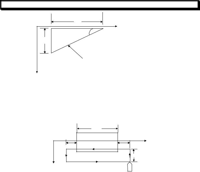
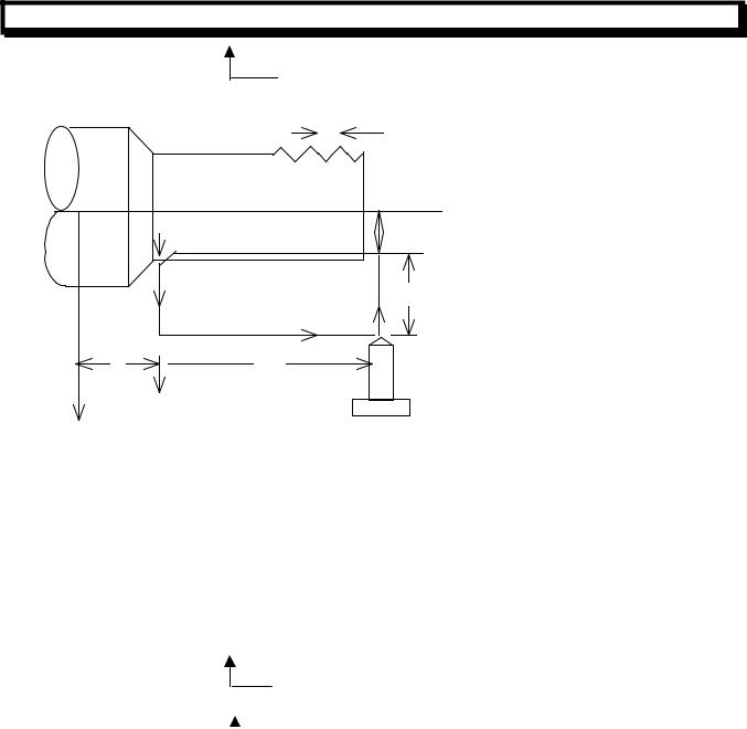
2.3.4Thread Cutting (G32)
Equal lead straight thread, tapered screws and scroll threads can be cut by using Command G32.
L |
L |
|
Metric thread can be cut by using the below command (the lead of the thread is specified by F address):
G32 X (U) _Z(W) _F_;(Metric thread)
F address specify the lead in long axis ranged from 0.001 to 500.000mm
Inch thread can be cut by using the below command(the teeth number is specified by I address): G32 X (U) _Z(W) _I_;(Inch thread)
I address specified the teeth number per inch in long axis ranged from 0.060 to 254000.000 teeth/inch. (Example)
G32 X__Z__F__;
|
|
L |
|
|
Z axis |
|
|
δ1 |
X |
Z |
Start point |
|
|
|
|
|
δ2 |
|
X axis |
End point |
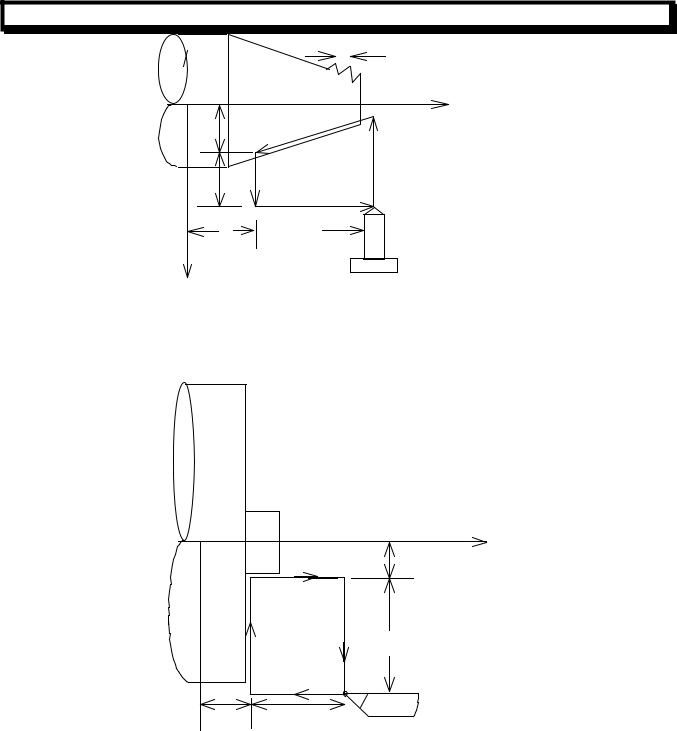
In general, the thread cutting need to repeat along the same path in rough cutting through finish cuts for a thread. Since the thread cutting starts when a I-revolution signal is output from the spindle position encoder, thread cutting is started at a fixed point and the tool path on the workpiece is unchanged for repeated threading cutting. The spindle speed must remain constant from rough cutting through finish cutting. if not, thread lead error will occur.
GUANGZHOU CNC EQUIPMENT CO., LTD.
11
GSK980T CNC SYSTEM USER MANUAL
LZ |
Z |
|
|
|
α |
LX |
|
|
Tapered thread |
X |
|
Ifα≤45°the lead is LZ Ifα 45°the lead is LX
The lead always is specified in radius.
The lead can not be cut correctly due to reason of deceleration and acceleration in the beginning and ending of the threading cutting, To cut a correct lead, the programmed length of the thread must be longer than the actual length of the thread.
Example: thread cutting
70mm
|
Z |
δ2 |
δ1 |
|
30mm |
X |
|
Lead of thread: 4mm δ1=3mm δ2=1.5 mm
Depth of cutting in X-axis direction: 1MM(cut twice) (Metric input, diameter programming)
G00 U-62.0;
G32 W_74.5 F4.0;
G00 U62.0;
W74.5
U-64.0;(Cut 1MM more in second cut ) G32 W-74.5 F4.0;
G00 U64.0 W74.5;
GUANGZHOU CNC EQUIPMENT CO., LTD.
12
GSK980T CNC SYSTEM USER MANUAL
|
|
|
|
|
|
|
|
|
|
|
|
|
|
|
|
|
|
|
|
|
|
|
|
|
|
|
|
|
30mm |
|
|
|
|
|
|
|
40mm |
|
|
|
|
|
|
φ14.0 |
|
||||||
|
|
|
|
|
|
|
|
|
|
|
|
|
|
|
|
|
|||||||||
|
|
|
|
|
|
|
|
|
|
|
|
|
|
|
|
|
|||||||||
|
|
|
|
|
|
|
|
|
|
|
|
|
|
|
|
||||||||||
|
|
|
|
|
|
|
|
|
|
|
|
|
|
|
|
|
|
||||||||
|
|
|
|
|
|
|
|
|
|
|
|
|
|
|
|
||||||||||
|
|
|
|
|
|
|
|
|
|
|
|
|
|
|
δ1 |
|
|
|
Z |
|
|||||
|
|
|
|
|
|
|
|
|
|
|
|
|
|
|
|
|
|
|
|
|
|
|
|||
|
|
|
|
|
|
|
|
|
|
|
|
|
|
|
|
|
|
|
|
|
|
|
|||
|
|
|
|
|
|
|
|
|
|
|
|
|
|
|
|
|
|
|
|
|
|
|
|||
|
|
|
|
|
|
|
|
|
|
|
|
|
|
|
|
|
|
|
|
|
|
|
|||
|
|
|
|
|
|
|
|
|
|
|
|
|
|
|
|
|
|
|
|
|
|
|
|
||
|
|
|
|
|
|
|
|
|
|
|
|
|
|
|
|
|
|
|
|
|
|
|
|
|
|
|
|
|
|
|
|
|
|
|
|
|
|
|
|
|
|
|
|
|
|
|
|
|
|
|
|
|
|
|
φ43.0 |
|
|
δ2 |
|
|
|
|
|
|
|
|
|
|
|
|
|
|
|||||
|
|
|
|
|
|
|
|
|
|
|
|
|
|
|
|
|
|
|
|
|
|
|
|||
|
φ50.0 |
|
|
|
|
|
|
|
|
|
|
|
|
|
|
|
|
|
|
||||||
|
|
|
|
|
|
|
|
|
|
|
|
|
|
|
|
|
|
|
|
|
|||||
|
|
|
|
|
|
|
|
|
|
|
|
|
|
|
|
|
|
|
|
|
|
|
|
|
|
|
|
|
|
|
|
|
|
|
|
|
|
|
|
|
|
|
|
|
|
|
|
|
|
|
|
|
|
|
|
|
|
|
|
|
|
|
|
|
|
|
|
|
|
|
|
|
|
|
|
|
|
|
|
|
|
|
|
|
|
|
|
|
|
|
|
|
|
|
|
|
|
|
|
|
|
|
|
|
|
|
|
|
|
|
|
|
|
|
|
|
|
|
|
|
|
|
|
|
|
|
|
|
|
|
|
|
|
|
|
|
|
|
|
|
|
|
|
|
|
|
|
|
|
|
|
|
|
|
|
X
Lead of thread :In Z axis direction:3.5mm δ1=2mm
δ2=1mm
Depth of cutting in X axis direction:1MM(cut twice) Using the above mentioned data to program: (Metric Input, diameter programming)
G00 X12.0 Z72.0;
G32 X41.0 Z29.0 F3.5;
G00 X50.0 Z72.0;
X10.0; (1MM more in second cut) G32 X39.0 Z29.0
G00 X50.0 Z72.0:
Note1: When the previous block also was a thread cutting block, the cutting will start immediately without detecting the 1-revolution signal.
G32 Z__F__;
Z__; (1-revolution signal is not detected before the executing of this block) G32__; (this block also is thread cutting block)
Z__F__;(1-revolution signal is also not detected)
GUANGZHOU CNC EQUIPMENT CO., LTD.
13
GSK980T CNC SYSTEM USER MANUAL
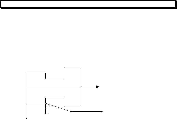
2.3.5Return to Reference Point Automatically (G28)
G28 X (U)__Z(W)__;
This command can make the tools return to reference point automatically via an intermediate position, the intermediate position is specified by addresses X(U)__Z(W).
(1)Positioning from the present position to the intermediate position of the designated axis at rapid traverse rate(point A→point B).
(2)Return to reference point from the intermediate position at rapid traverse rate(point B→point R). (3)If the machine lock is turn off, when the tool has returned to the reference point, the reference point return completion led goes on.
|
G28 X40 Z50 |
|
|
|
Z |
|
|
Reference point R |
|
Present |
|
|
Point A |
Intermediate point |
|
|
|
X |
|
B (40, 50) |
Note1: If returning to the reference point manually has never been done after power on ,the motion of returning to the reference point automatically from the intermediate point in G28 is same as that in manual way. The direction of intermediate point is specified by parameter No.006(ZMX,ZMZ).
Note2:If the start point of machining program is same as the reference point ,doing G28 can return to the start point of machining program.
Note3:If the start point of machining program is not same as the reference point ,returning to the start point of machining program can be realized by rapid positioning command or operation of returning to the start point, not by G28.
2.3.6Dwell(G04)
By specifying a dwell, the execution of the next block is delayed by the specified time. Format:
G04 P__; or G04 X__; or G04 U__;
The unit of the delay time is second. Command value of the dwell time is from 0.001 to 99999.999second. If addresses P, X is omitted, this command can specified an exact stop.
2.3.7Work Coordinate System Setting(G0)
A work coordinate system can be set using the following the blow command: G50 X(x) Z(z);
Use this command to set a coordinate system ,this coordinate system is referred as a workpiece coordinate system, so a point on the tool, such as the tool tip ,is specified as coordinate value(x, z). Once a workpiece coordinate system has been set, the absolute position of following blocks is specified according to this coordinate system
When diameter programming, X address is specified by diameter value. When radius programming, X address is specified by radius value.
GUANGZHOU CNC EQUIPMENT CO., LTD.
14

GSK980T CNC SYSTEM USER MANUAL
(Example) Coordinate system setting with diameter designation
G50 X100.0 Z150.0;
 Z 100.00mm
150.00mm |
Start point = reference point |
|
X
As illustrated in above figure, the reference point on the turret is superposition with the start point, and the coordinate system is set by G50 at the start of the program. Thus, when an absolute command is carried out, The start point will move to the position commanded. In order to move the tool tip to the position commanded, the difference between the reference and the tool tip is compensated by the too offset.
Note: If the coordinate system setting is carried out by G50, a coordinate system in which the position prior to the effecting of the offset becomes the designated position, is set.
2.3.8Feed per Minute (G98)
G98 specify the feed per minute, a number follows F specify the amount of feed of the cutting tool per minute.
G98 is a modal code. Once a G98 is specified, it is available until a G99 (feed per revolution )is specified.
2.3.9Feed per Revolution(G99)
G99 specified the feed per spindle revolution. A number follows F specified the amount of feed the cutting tool per spindle revolution.
G99 is also a modal code, once a G99 is specified; it is available until a G98 is specified.
GUANGZHOU CNC EQUIPMENT CO., LTD.
15
GSK980T CNC SYSTEM USER MANUAL
Table 2.3.9 Feed Per Minute and Feed Per Revolution
|
Feed per minute |
|
Feed per revolution |
Address |
F |
|
F |
Command |
G98 |
|
G99 |
code |
|
||
|
|
|
|
Command |
1~8000mm/min |
|
0.01~500.00mm/rev |
ranges |
(F1~F8000) |
|
(F1~F50000) |
|
The limitation takes place at a certain specified speed for both feed per |
||
Limitation value |
minute and feed per revolution. This clamping value is set by the machine |
||
|
tool builder. (Override is applied to implement clamping of speed) |
||
Override |
An override from 0~150%(10%per step)can be applied to both feed per |
||
minute mode and feed per revolution mode |
|
||
|
|
||
Note: when using feed per revolution mode, if it necessary to affix a position encoder to the spindle.
GUANGZHOU CNC EQUIPMENT CO., LTD.
16
GSK980T CNC SYSTEM USER MANUAL
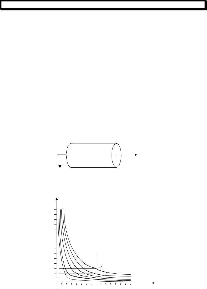
2.3.10Constant Surface Speed Control(G96, G97)
When the surface speed is set by a value after address S, and the spindle speed is calculated according to the relative position between the tool and the workpiece to keep the surface speed always the specified value, so-called constant surface speed control. Voltage is fed to the spindle control section so that the spindle rotates to produce the correct surface speed.
The units of the surface speed is as follows:
Input unit |
Surface speed unit |
Metric system |
m/min |
The units of the surface speed depend on the setting of the machine tool builder. The Constant surface speed control is specified by the follow command:
G96 S__;
The surface speed is set after address S.
The constant speed control can be canceled by the following command: G97 S__;
The spindle speed is set after address S.
It is necessary to apply the constant speed control on Z axis.
|
|
|
|
|
|
|
|
|
|
|
|
Z |
|
X |
|
|
|
|
|
|
|
|
|
|
|
Spindle speed (rpm) |
|
|
|
|
|
|
|
|
|
|
||
n |
|
|
|
|
|
|
|
|
|
|
|
|
3000 |
|
|
|
|
|
|
|
|
|
|
|
|
2800 |
|
|
|
|
|
|
|
As show |
in the |
figure, |
the spindle |
|
2600 |
|
|
|
|
|
|
|
speed (rpm) coincides with the surface4 |
||||
2400 |
|
|
|
|
|
|
|
speed |
(m/min) |
at |
approx. |
|
2200 |
|
|
|
|
|
|
|
160mm(radius). |
|
|
||
|
|
|
|
|
|
|
|
|
|
|
|
|
2000 |
|
|
|
|
|
|
|
|
|
|
|
|
1800 |
|
|
|
|
|
|
|
|
|
|
|
|
1600 |
|
|
|
|
|
|
|
|
|
|
|
|
1400 |
|
|
|
|
|
|
|
|
|
|
|
|
1200 |
|
|
|
|
|
|
|
|
|
|
|
|
1000 |
|
|
|
|
S |
|
|
|
|
|
|
|
800 |
|
|
|
4 |
600 |
|
|
|
|
|
||
|
|
30 |
0 |
0 |
m |
|
|
|
|
|||
600 |
|
|
|
|
min |
|
|
|
||||
|
|
0 |
|
|
|
|
|
|||||
400 |
5 |
10 |
0200 |
|
|
|
|
|
|
|
||
200 |
0 |
|
|
|
|
|
|
|
|
|
|
|
|
|
|
|
|
|
|
|
|
|
|
|
|
0 |
|
|
|
|
|
|
|
|
|
|
|
|
|
20 40 |
60 80 100120140160180200220240260280300 |
mm |
|||||||||
|
0 |
|
|
|
|
|
|
|
|
|
|
|
GUANGZHOU CNC EQUIPMENT CO., LTD.
17
GSK980T CNC SYSTEM USER MANUAL
(1)Spindle Speed Override
An override for the specified surface speed or the spindle speed can be specified in 50,60,70,80,90,100,110,120%
(2)Maximum Spindle Speed Limitation
The value follows G50 S specify the maximum spindle speed for constant surface speed control in rpm:
G50 S__;
When the spindle speed in constant surface speed control reaches the value specified in the above command, the spindle speed is clamped at this maximum value.
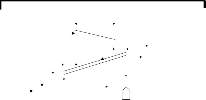
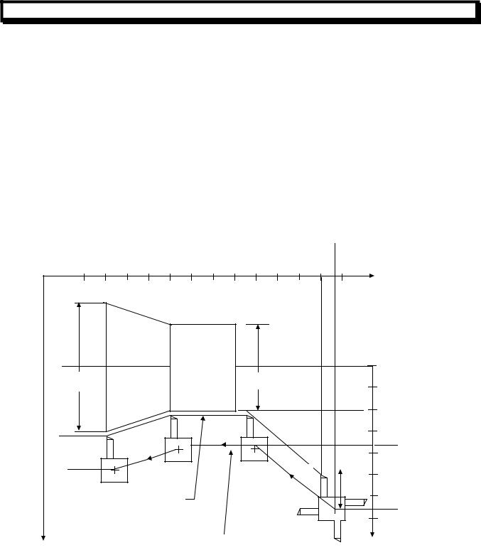
(3)Constant Surface Speed Control for Rapid Traverse(G00)
For a Block in which G00is specified, the constant surface speed control is made by calculating the surface speed based on the position at the end point of the rapid traverse block instead of calculating the surface speed to a transient change of the tool position, Because at rapid traverse condition, cutting is not executed.
(Example:)
|
|
|
|
|
|
|
1050 |
|
|
|
|
|
|
300 |
400 |
500 |
600 |
700 |
800 |
900 |
1000 |
1100 |
1200 |
1300 |
1400 1500 |
|
|
|
|
|
|
|
|
|
|
|
|
|
|
|
Z |
Φ600 |
|
|
|
|
|
|
|
Φ400 |
|
|
|
100 |
|
|
|
|
|
|
|
|
|
|
|
|
|
|
|
|
|
|
|
|
|
|
|
|
|
|
|
|
200 |
|
|
|
|
|
|
|
|
|
|
|
|
|
300 |
|
|
|
N15 |
|
|
|
|
|
|
|
|
|
375 |
|
|
|
|
|
|
N14 |
|
|
|
|
|
|
400 |
|
|
|
|
|
|
|
|
|
|
|
|
|
|
N1 |
|
|
|
|
|
|
|
|
N11 |
3 |
|
|
500 |
|
|
|
|
|
|
|
|
|
|
4 |
|
||
|
|
|
|
|
|
|
|
|
|
|
|
||
|
Programmed path |
|
|
|
|
|
|
|
600 |
||||
|
|
|
|
|
|
|
|
|
|||||
|
|
|
|
|
|
|
|
|
675 |
||||
|
|
|
|
|
|
|
|
|
|
|
|
|
|
|
|
|
|
|
|
|
|
|
|
|
|
|
700 |
|
|
Path after compensation |
|
|
|
2 |
|
|
|
||||
|
|
|
|
|
|
|
|
|
|||||
X |
|
|
|
|
|
|
|
|
|
|
1 |
Radius value |
|
(Diameter programming) |
|
|
N8 G00 X1000.Z1400.; |
|
|
N9 T0303; |
|
|
N11 X400.Z1050.; |
|
|
N12 G50 |
S3000; |
(Designation of Maximum spindle speed) |
N13 G96 |
S200; |
(Surface speed 200m/,in) |
N14 G01 |
Z700. F1000; |
|
N15 X600. Z400.;
GUANGZHOU CNC EQUIPMENT CO., LTD.
18

GSK980T CNC SYSTEM USER MANUAL
N16 Z....;
The CNC use the programmed coordinate value on the X axis to calculate the surface speed. When offset compensation is valid, this is not the value calculated according to the X axis coordinate after offset. At the end point N15 in example above is not the turret center, but the tool nose, that is to say at 600dia, the surface speed is 200m/min. If X axis coordinate value is negative, the CNC uses the absolute value.
GUANGZHOU CNC EQUIPMENT CO., LTD.
19
GSK980T CNC SYSTEM USER MANUAL
2.3.11Canned Cycle(G90, G92 G94)
For repetitive machining peculiar to turning, such as the metal removal in rough cutting, the cutting of the same path is made repetitively, by using these cycles. The said cutting specified in a range of three to several dozen blocks can be specified in one block. In addition, only the values to be changed need to be specified for repetition, the program using this cycle is very simple and useful.
The drawings in the examples below are for diameter programming. In radius programming, change U/2 or X/2 to U or X respectively.
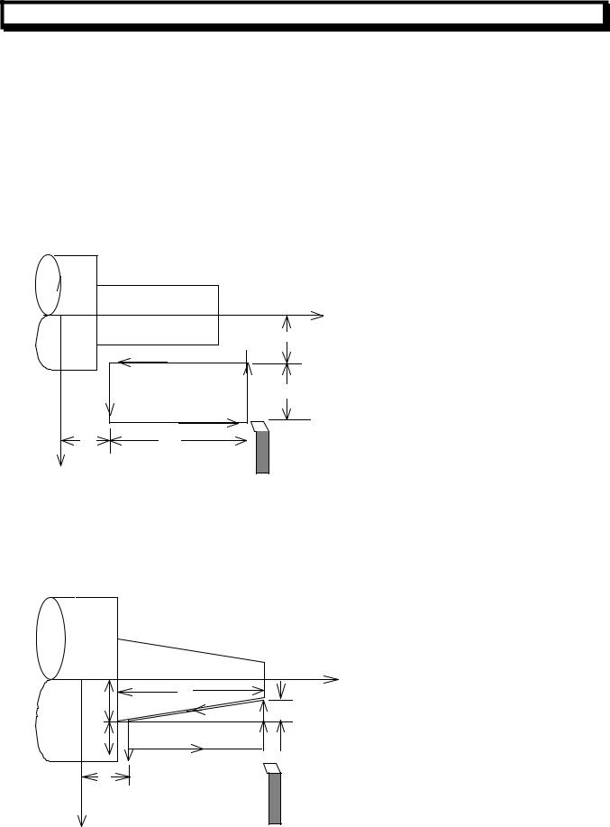
(1)Outer Diameter/Internal Diameter Cutting Cycle(G90)
(a)Cylinder cutting cycle G90 X (U)__Z(W)__F__;
Z axis
|
|
|
X/2 |
|
2 F |
|
|
3 F |
1 R |
|
U/2 |
Z |
4 R |
|
F Cutting feed |
|
|||
W |
|
||
|
|
||
|
|
|
R:Rapid traverse |
Xaxis
Tool
In incremental programming, the signs of the numbers following address U and W depend on the direction of paths1 and 2, in the cycle of above figure, the signs of U and W are negative. In single block mode, Operation of 1,2,3,4 are performed by pressing the cycle start key.
(b)Taper cutting cycle
G90 X (U)__Z(W)__R__F__;
Z axis
W
X/2 2 F
R
U/2 |
3 F |
1 R |
4 R
Z
F Cutting feed
R:Rapid traverse
X axis |
Tool |
GUANGZHOU CNC EQUIPMENT CO., LTD.
20
GSK980T CNC SYSTEM USER MANUAL
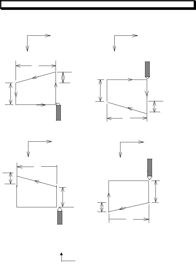
In incremental programming, the relation between the signs of the numbers following the address U
W R, and the tool paths are as follows: 1) U <, W<0, R<0
Z
X
W
R
|
|
2(F) |
U/2 |
3(F) |
1(R) |
|
|
4(R) |
2) U >0, W<0, R>0
Z
X
|
|
4(R) |
U/2 |
3(F) |
1(R) |
|
|
|
|
|
2(F) |
R
|
|
|
W |
|
|
U<0, W<0, R>0 |
|
|
4) U>0, W<0, R<0 |
|
|
But R ≤ U/2 |
|
|
But R ≤ U/2 |
|
|
|
Z |
|
|
|
Z |
X |
|
|
X |
|
|
W |
|
|
|
|
|
R |
|
|
4(R) |
|
|
|
|
|
|
|
|
2(F) |
|
|
|
|
|
3(F) |
1(R) |
U/2 |
3(F) |
1(R) |
U/2 |
|
|
|
|||
|
|
|
2(F) |
|
|
|
|
|
R |
|
|
4(R) |
|
|
|
|
|
|
|
|
W |
|
|
(2) Thread Cutting Cycle (G92)
(a) Straight thread cutting
G92X (U)__Z(W)__F__; (Metric thread)
Pitch specified (L)
G92X (U)__Z(W)__I__; (Inch thread)
GUANGZHOU CNC EQUIPMENT CO., LTD.
21
GSK980T CNC SYSTEM USER MANUAL
Pitch specified (Number of teeth/inch)
Note: Address I for inch thread is not a modal command.
L
|
Width of chanferring |
Z axis |
|
X/2 |
|
|
|
|
|
2 F |
|
|
3 R |
U/2 |
|
1 R |
|
|
|
|
|
4 R |
|
Z |
W |
F Cutting feel |
|
||
|
|
R:Rapid traverse |
X axis |
|
Tool |
|
|
In incremental programming, the signs of values of U and W commands depend on the direction of paths 1 and 2. It is to say, if the direction of path 1 is negative along X axis, the value of U is negative. The command of the lead of thread and the limitation of spindle is same with command G32. In single block mode, single block is effective for operation1,2,3,4.
The length of the chamfering is set by parameter No.019THDCH. The width of the chamfering is set by parameter No.THDCH*1/10*L (lead of thread)
Note 1:As mentioned in Note of G32.And, When the FEED HOLD key is pressed during the execution of the thread cutting block, the feed would not stop until path 3 is finished.
(b)Taper Thread Cutting Cycle: G92 X (U)__Z (W)__R__F__;
lead specified (L)
G92 X (U)__ Z (W)__R__I__;

 lead specified (number of teeth/inch)
Note: Address I for inch thread is not a modal command.
GUANGZHOU CNC EQUIPMENT CO., LTD.
22
GSK980T CNC SYSTEM USER MANUAL
|
L |
|
|
|
Z axis |
X/2 |
2 F |
|
|
|
|
U/2 |
1 R |
|
3 R |
|
|
|
4 R |
F Cutting feed |
|
|
|
|
|
R:Rapid traverse |
Z W
W
X axis |
Tool |
|
(3) End Face Cutting Cycle(G94)
(a)End Face Cutting Cycle
G94 X (U)__ Z(W)__F__;
o |
Zaxis |
|
X/2 |
||
|
||
|
3 F |
2 F
4 R U/2
1 R |
F Cutting feed |
|
R:Rapid traverse
W
X axis |
Tool |
|
In incremental programming, the signs of the value following address U and W depend on the direction of paths 1 and 2. That is, if the path 1 is negative along Z axis, the sign of the value of W is negative.
In single running mode, press Cycle start Key to perform the operation 1,2,3 and 4. (b)Taper Face Cutting Cycle
G94 X (U)__Z (W)__R__F__;
GUANGZHOU CNC EQUIPMENT CO., LTD.
23

GSK980T CNC SYSTEM USER MANUAL
|
|
|
|
|
|
|
|
|
|
|
|
|
|
|
|
|
|
|
|
|
|
|
|
|
|
|
|
|
|
|
|
Z axis |
|
|
|
|
|
|
|
|
|
|
|
|
|
|
|
|
|
|
|
X/2 |
|
|
|
|
|
|
|
|
|
|
|||||
|
|
|
|
|
|
|
|
|
|
|
|
|
|
|
|
|
|
|
|
|
|
|
|
|
|
|
|
|
|
|
|
|
|
|
|
|
|
|
|
|
|
|
|
3 F |
|
|
||||
|
U/2 |
|
|
2 F |
4 R |
|
||||||||||
|
|
|
|
|
|
|
|
|
1 R |
|
|
|||||
|
|
|
|
|
|
|
|
|
|
|
||||||
|
|
|
|
|
|
|
|
|
|
|
|
|
|
|
|
|
|
|
|
|
|
|
|
R |
|
|
|
W |
F Cutting feed |
|
|||
|
|
|
|
|
|
|
|
|
|
|
||||||
|
|
|
|
|
Z |
|
|
|
|
|
|
|
||||
|
|
|
|
|
|
|
|
|
|
|
R:Rapid traverse |
|
||||
|
|
|
|
|
|
|
|
|
|
|
|
|
|
|
|
|
X axis
In incremental programming, the relationship between the signs of the values of U, W and R and the
tool paths is as follows: |
|
|
|
|
|
1) U<0, W<0, R<0 |
|
|
2)U>0, W<0, R<0 |
|
|
|
W |
|
|
R |
|
|
|
|
|
|
|
|
3(F) |
|
|
|
|
|
|
|
|
|
1(R) |
U/2 |
2(F) |
4(R) |
|
|
|
|
|
|
U/2 |
2(F) |
4(R) |
|
|
|
|
|
|
|
1(R) |
|
|
|
3(F) |
|
|
|
|
|
|
|
R |
|
|
|
W |
|
|
|
|
|
|
3)U<0, W<0, R>0( R ≤ W ) |
4)U>0, W<0, R>0( R ≤ W ) |
||||
|
W |
|
|
|
|
|
R |
|
|
|
|
|
3(F) |
|
|
|
1(R) |
|
2(F) |
|
|
|
|
|
|
|
U/2 |
|
4(R) |
U/2 |
|
4(R) |
|
|
|
|
|
2(F) |
|
||
|
|
|
|
|
|
|
1(R) |
|
|
|
3(F) |
|
|
|
|
R |
|
|
|
|
|
|
W |
Note 1: The data value of X (U), Z (W) and R of during canned cycle are modal as same as G90,G92 and G94, if X (U), Z (W) or R is not newly commanded, the previously commanded
GUANGZHOU CNC EQUIPMENT CO., LTD.
24
GSK980T CNC SYSTEM USER MANUAL
data is still effective.
In the example below, a canned cycle can be repeated only by specifying the new movement commands for X axis, but the Z axis movement need not be re-commanded.
However, these data are cleared if a one-shot G code expect G04 or a G code, which is not in the same group with G90, G92 and G94, is command.
(Example):
Z axis
O
16
12
8
4
66
X axis
The following program can perform the cycle in the above figure: N030 G90 U-8.0 W-66.0 F4000;
N031 U-16.0;
N032 U-24.0;
N033 U-32.0;
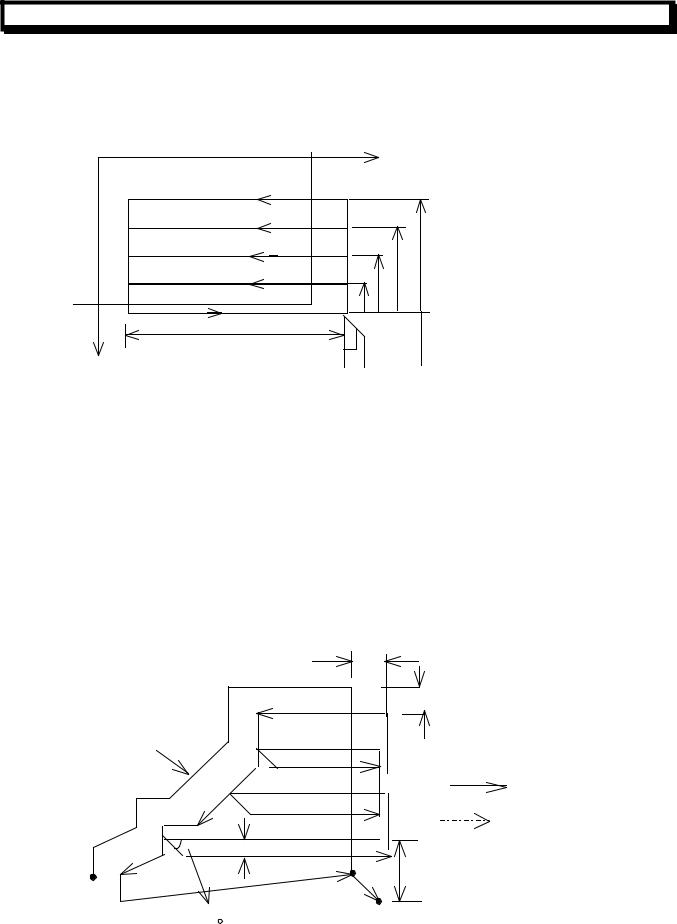
2.3.12Multiple Repetitive Cycle (G70~G75)
This optional canned cycle function is used to make the programming easy. For example, the data for the finish workpiece shape can be used as the data for rough cutting automatically.
(1)Multiple Repetitive Cycle for Outer Diameter (G71)
As in the figure below, a finished shape of A to A’ to B is given by a program, the specified area is removed by depth of cut D, and the finish cutting allowance of U/2, and W is left.
W
 Aˊ
Aˊ
U/2
Program commanded path
Cutting feed
Rapid traverse
|
|
E |
B |
|
D |
|
|
|
|
|
A |
|
45 |
C |
|
|
GUANGZHOU CNC EQUIPMENT CO., LTD.
25
 Loading...