


GV-27
GRUNDIG GV 27, GV 27 VPS/5, GV 47, GV 47 VPS/5, GV 7000 SV Service Manual
...
Service Manual
Video
GV 27
GV 27 VPS/5
GV 47
GV 47 VPS/5
GV 7000 SV
GV 7000 SV-C
PAL / SECAM
GV 7003
GV 7300 SV
GV 7300 SV/5
GV 7400 HiFi
GV 7400 HiFi/5
GV 7400 NIC
KV 7001 VPS/5
KV 7301 VPS/5
Palermo /SE 7100 SV
Sevilla/SE 7105 HiFi
Service
Manual
GV 27…
GV 47…
GV 7…
Sach-Nr./Part No.
72010-530.25
Zusätzlich erforderliche
Unterlagen für den Komplettservice
Additionally required
Service Manuals for the Complete Service
Service
Manual
Sicherheit
Safety
Sach-Nr./Part No.
72010-800.00
Service
Training
GV 27…
GV 47…
GV 7…
Sach-Nr./Part No.
j 72010-531.40
k 72010-531.41
Btx * 32700 #
Sachnummer
Part Number 72010-530.25
Änderungen vorbehalten
Subject to alteration
Printed in Germany
VK21/VK211 0997

Allgemeiner Teil / General Section GV 27 …, GV 47 …, GV 7…
Es gelten die Vorschriften und Sicherheitshinweise
gemäß dem Service Manual "Sicherheit", Sach-Nummer 72010-800.00, sowie zusätzlich die eventuell
abweichenden, landesspezifischen Vorschriften!
D
Inhaltsverzeichnis
Seite
Allgemeiner Teil .................................1-1…1-12
Geräteübersicht ........................................................................... 1-3
Meßgeräte / Meßmittel................................................................. 1-5
Technische Daten ........................................................................ 1-5
Bedienelemente ........................................................................... 1-7
Servicehinweise ........................................................................... 1-9
Servicetestprogramm
und Sonderfunktionen.........................2-1…2-3
Abgleichvorschriften ........................... 3-1…3-2
Chassisplatte (QMB).................................................................... 3-1
• Netzteil (PS).............................................................................. 3-1
• Bedieneinheit (DC).................................................................... 3-1
• Laufwerksteuerung / Deck-Elektronik (DE)............................... 3-1
• Empfangseinheit (FV) ............................................................... 3-2
• Video/Chroma (VS, VS-S) ........................................................ 3-2
• Standardton (AL)....................................................................... 3-2
The regulations and safety instructions shall be valid
as provided by the "Safety" Service Manual, part
number 72010-800.00, as well as the respective
national deviations.
GB
Table of Contents
Page
General Section..................................1-1…1-12
Videorecorder Overview .............................................................. 1-3
Test Equipment / Jigs .................................................................. 1-5
Specifications............................................................................... 1-5
Operating Hints ............................................................................ 1-7
Service Instructions...................................................................... 1-9
Service Test Programme
and Special Functions .........................2-4…2-6
Adjustment Procedures.......................3-3…3-4
Chassis Board (QMB) .................................................................. 3-3
• Power Supply (PS).................................................................... 3-3
• Keyboard Control Unit (DC) ...................................................... 3-3
• Deck Control / Deck Electronic (DE)......................................... 3-3
• Frontend (FV)............................................................................ 3-4
• Video/Chroma (VS, VS-S) ........................................................ 3-4
• Standard Sound (AL) ................................................................ 3-4
Platinenabbildungen
und Schaltpläne ................................ 4-1…4-40
Abkürzungen................................................................................ 4-1
Verdrahtungsplan......................................................................... 4-3
Blockschaltpläne .......................................................................... 4-4
• Netzteil / Bus-System................................................................ 4-4
• Video/Chroma ........................................................................... 4-7
• Standardton ............................................................................ 4-10
• FM-Ton ................................................................................... 4-11
• Digital ...................................................................................... 4-13
Chassisplatte (QMB).................................................................. 4-15
• Empfangseinheit (FV) ............................................................. 4-21
• OSD (OS)................................................................................ 4-24
• Follow-TV (FM) ....................................................................... 4-24
• VPS/PDC (VP) ........................................................................ 4-24
• Video/Chroma (VS)................................................................. 4-25
• Standardton (AL)..................................................................... 4-25
• IN/OUT (IO)............................................................................. 4-27
• SECAM-L (VS-S) .................................................................... 4-28
• FM-Ton (AF) ........................................................................... 4-29
• Kopfverstärker (HA) ................................................................ 4-30
• Netzteil (PS)............................................................................ 4-31
• Laufwerksteuerung / Deck-Elektronik (DE)............................. 4-33
• Bedieneinheit (DC).................................................................. 4-35
NICAM-Decoder (QNIC) ............................................................ 4-36
Oszillogramme ........................................................................... 4-38
Laufwerk .............................................5-1…5-12
Meßgeräte / Meßmittel................................................................. 5-1
Servicehinweise ........................................................................... 5-2
Auswechseln von Laufwerksteilen ............................................... 5-3
Einstellungen ............................................................................. 5-10
Layout of the PCBs
and Circuit Diagrams .........................4-1…4-40
Abbreviations ............................................................................... 4-1
Wiring Diagram ............................................................................ 4-3
Block Circuit Diagram .................................................................. 4-4
• Power Supply / Bus System...................................................... 4-4
• Video/Chroma ........................................................................... 4-7
• Standard Sound ...................................................................... 4-10
• FM Sound ............................................................................... 4-11
• Digital ...................................................................................... 4-13
Chassis Board (QMB) ................................................................ 4-15
• Frontend (FV).......................................................................... 4-21
• OSD (OS)................................................................................ 4-24
• Follow-TV (FM) ....................................................................... 4-24
• VPS/PDC (VP) ........................................................................ 4-24
• Video/Chroma (VS)................................................................. 4-25
• Standard Sound (AL) .............................................................. 4-25
• IN/OUT (IO)............................................................................. 4-27
• SECAM L (VS-S) .................................................................... 4-28
• FM Sound (AF) ....................................................................... 4-29
• Head Amplifier (HA) ................................................................ 4-30
• Power Supply (PS).................................................................. 4-31
• Drive Control / Deck Electronic (DE)....................................... 4-33
• Display Control (DC) ............................................................... 4-35
NICAM Decoder (QNIC) ............................................................ 4-36
Oscillograms .............................................................................. 4-38
Drive Mechanism................................5-1…5-12
Test Equipment / Jigs .................................................................. 5-1
Service Instructions...................................................................... 5-2
Replacement of Tape Deck Components .................................... 5-3
Adjustments ............................................................................... 5-10
Explosionszeichnungen
und Ersatzteillisten ............................6-1…6-20
1 - 2 GRUNDIG Service
Exploded Views and
Spare Parts Lists................................6-1…6-20
GV 27 …, GV 47 …, GV 7… Allgemeiner Teil / General Section
Allgemeiner Teil / General Section
Geräteübersicht / Video Recorder Overview
GV 27 …, GV 47 …, GV 7… Allgemeiner Teil / General Section
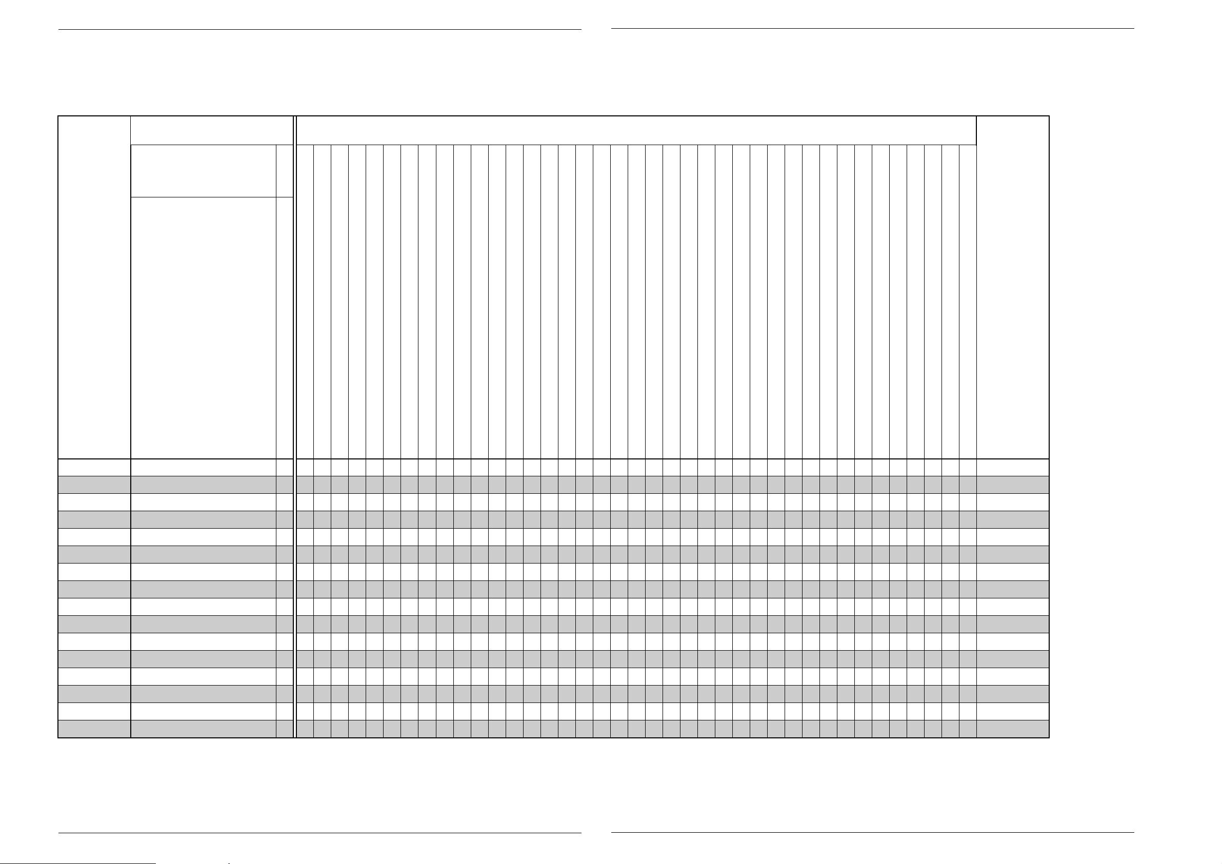
Bausteinübersicht
Table of Moduls
S./P 4-15
S./P 4-21
S./P 4-24
S./P 4-24
S./P 4-24
S./P 4-25
S./P 4-25
S./P 4-27
S./P 4-29
S./P 4-30
S./P 4-31
S./P 4-33
S./P 4-35
Feature-Übersicht
Table of Features
S./P 4-36NICAM-Decoder (QNIC)
GV 27
GV 27 VPS/5
GV 47
GV 47 VPS/5
GV 7000 SV
GV 7000 SV-C
GV 7003
GV 7300 SV
GV 7300 SV/5
GV 7400 HiFi
GV 7400 HiFi/5
GV 7400 NIC
KV 7001 VPS/5
KV 7301 VPS/5
SE 7100 SV
SE 7105 HiFi
Chassisplatte / Chassis Board (QMB)
· Empfangseinheit / Frontend (FV)
· OSD (OS)
· Follow TV (FM)
· VPS/PDC (VP)
· Video/Chroma (VS)
· Standardton / Standard Sound (AL)
· IN/OUT (IO)
· FM-Ton / FM Sound (AF)
· Kopfverstärker / Head Amplifier (HC)
· Netzteil / Power Supply (PS)
· Laufwerkssteuerung / Deck Electronic (DE)
· Bedieneinheit / Keyboard Control (DC)
• • • • • • • • • • • • • • • •
CCIR, B/G/H - PAL
• • • • • • • • • • • • • • • •
• • •
S-VHS-Aufnahme / S-VHS Record
NTSC-Wiedergabe / NTSC Playback
NICAM
CCIR, B/G/D/K - SECAM
• • • • • •
• • • • • • • • • •
• • •
Longplay
Normalplay
HiFi-Stereo
Rotierender Löschkopf / Flying Erase Head
2 Kopf / Head (Audio)
4 Kopf / Head (Video)
2 Kopf / Head (Video)
S-VHS-Wiedergabe / S-VHS Playback
• • • • • • •
• • • • • • • • •
• • • •
• • • • • • • • • • • • • • • •
• • • • • • • • •
• • • •
• • • • •
Teletext "DOS"
99 Programme
SHOW VIEW
6 Timer
PDC
VPS
Follow TV
Megalogic
Energiesparend / Low Power (Standby <6W)
• • • • • • • • • • • • • • • •
• • • • • • • • • • • • • • • •
• • • • • • • • • • • • • •
• • • • • • • • • • • •
• • • • • • •
• • • • • • • • • •
• • • • • • • • • •
VISS
Insert-Schnitt / Insert Edit
Nachvertonung / Dubbing
Kindersicherung / child lock
OSD
• • • • • • • • • • • • • • • •
• • • •
SAT-Steuerbuchse / SAT Remote Control
RS232-Buchse / Socket
Kopfhörerbuchse / Headphone Jack
Mikrofonbuchse / Micro Jack
"SYNCHRO-EDIT"-Buchse / Socket (ø 2,5mm Klinkenbuchse / mini-minijack)
S-VHS-Buchsen / S-VHS Sockets (IN/OUT)
CV-Eingangs-Buchsen / Input Sockets
LINE-Ausgangs-Buchsen / Output Sockets
LINE-Eingangs-Buchsen / Input Sockets
"PAY-TV"-Buchse / Socket (EURO-AV2)
EURO-AV-Buchse / Socket
Akustische Funktionskontorlle / Acoustic Function Control
• • • • • • • • • • • • • • • •
• • • • • • •
• • • •
GV 27
GV 27 VPS/5
GV 47
GV 47 VPS/5
GV 7000 SV
GV 7000 SV-C
GV 7003
GV 7300 SV
GV 7300 SV/5
GV 7400 HiFi
GV 7400 HiFi/5
GV 7400 NIC
KV 7001 VPS/5
KV 7301 VPS/5
SE 7100 SV
SE 7105 HiFi
GRUNDIG Service 1 - 3
GRUNDIG Service 1 - 4

Allgemeiner Teil / General Section GV 27 …, GV 47 …, GV 7… Allgemeiner Teil / General Section GV 27 …, GV 47 …, GV 7…
Meßgeräte / Meßmittel
Regeltrenntrafo Farbgenerator
Zweikanaloszilloskop Tongenerator
Digitalmultimeter Stabilisiertes Netzgerät
Millivoltmeter Frequenzzähler
Beachten Sie bitte das Grundig Meßtechnik-Programm, das Sie unter
folgender Adresse erhalten:
Grundig Instruments
Test- und Meßsysteme GmbH
Würzburger Str. 150, D-90766 Fürth/Bay.
Tel. 0911/703-4118, Telefax 0911/703-4130
Sach-Nr.
Testcassette................................................................ 9.27540-1011
Testcassette (HiFi)...................................................... 9.27540-1016
Drehmomentmesser 600gf-cm ................................... 75987-262.72
Adapter für Drehmomentmesser 600gf-cm................. 75987-262.73
Einstellschraubendreher ............................................. 75987-262.80
Bandzug-Einstellgriff und -stift .................................... 75988-002.27
Kopfscheibenabzieher ................................................ 75988-002.37
Nylonhandschuhe ....................................................... handelsüblich
Tentelometer ............................................................... handelsüblich
Diese Meßmittel können Sie über die Serviceorganisation beziehen.
Wir weisen jedoch darauf hin, daß es sich hierbei z.T. um Meßmittel
handelt, die am Markt bereits eingeführt sind.
Testcassette Sach-Nr. 9.27540-1011
• Farbtestbild mit Dropout-Einblendung
• 6,3kHz-Senkrecht-Vollspuraufzeichnung und Bezugspegel 333Hz
in dreiminütigem Wechsel.
Testcassette (HiFi) Sach-Nr. 9.27540-1016
• Farbtestbild mit Dropout-Einblendung
• Längsspur-Ton: 6,3kHz und 333Hz
• FM-Ton: 1kHz Vollpegel (± 50kHz Hub)
Video-Lehrfilm Sach-Nr. 72007-744.81
• Laufwerk "High Speed Drive"
Test Equipment / Jigs
Variable isolating transformer Colour generator
Dual channel oscilloscope AF generator
Digital multimeter Stabilized power supply
Millivoltmeter Frequency counter
Please note the Grundig Catalog "Test and Measuring Equipment"
obtainable from:
Grundig Instruments
Test- und Meßsysteme GmbH
Würzburger Str. 150, D-90766 Fürth/Bay.
Tel. 0911/703-4118, Telefax 0911/703-4130
Part No.
Test cassette............................................................... 9.27540-1011
Test cassette (HiFi)..................................................... 9.27540-1016
Torquemeter 600gf-cm ............................................... 75987-262.72
Adapter for torquemeter 600gf-cm.............................. 75987-262.73
Adjustment screw driver.............................................. 75987-262.80
Tape tension adjustment tool - handle and pin ........... 75988-002.27
Headwheel extractor ................................................... 75988-002.37
Nylon gloves ...................................................... commonly available
Tentelometer ...................................................... commonly available
You can order these test equipments from the Service organization.
We refer to you that a number of these test equipments is already
obtainable on the market.
Test cassette Part No. 9.27540-1011
• Colour test pattern with dropout recording
• 6.3kHz vertical full-track recording alternating with 333Hz reference
level every 3 minutes.
Test cassette (HiFi) Part No. 9.27540-1016
• Colour test pattern with dropout recording
• Longitudinal track sound: 6.3kHz and 333Hz
• FM sound: 1kHz full level (± 50kHz deviation)
Video Training Film Part No. 72007-744.81
• Drive mechanism "High Speed Drive"
Anschlußmöglichkeiten:
EURO-AV1 / AV2
Audio
– Kontakt 1, Ausgang rechts ...........................500mV
– Kontakt 2, Eingang rechts .................................... 0,2…2V, ≥10kΩ
– Kontakt 3, Ausgang links..............................500mV
– Kontakt 6, Eingang links....................................... 0,2…2V, ≥10kΩ
±3dB, ≤1kΩ
eff
±3dB, ≤1kΩ
eff
Video
– Kontakt 19, Videoausgang (FBAS) ........... 1VSS +1dB / -2dB, 75Ω
– Kontakt 20, Videoeingang (FBAS) ....................... 1VSS ±3dB, 75Ω
Schaltspannung (bei nur einer EURO-AV-Buchse dient der Kontakt 8 als Aus- und Eingang)
– Kontakt 8,
Ausgang bei AV1
................ LOW 2V, HIGH 9,5V, Ansprechzeit 5ms, ≥10kΩ, ≤2nF
Eingang bei AV2............................. LOW 2V, HIGH ≥4,5V, ≥10kΩ
RGB (die Signale werden nur von der EURO-AV2 zur EURO-AV1-Buchse durchgeschleift)
– Kontakt 7, Blau
– Kontakt 11, Grün
– Kontakt 15, Rot
– Kontakt 16, Synchron
Audio-Ausgang (Geräterückseite)..................500mV
Hinweis:
±3dB, 1kΩ
eff
Diese Ausgänge sind den Ausgängen der EURO-AV1-Buchse parallel
geschaltet.
Modulator
Durchschleifbetrieb
– Frequenzgang .......................................................... 45…860MHz
– Dämpfung
Antenneneingang – TV-Ausgang .......................... 2dB +3dB/-2dB
Antenneneingang – Tuner-Ausgang ..................... 2dB +3dB/-2dB
Modulatorausgangskanal (über I
2
C-Bus einstellbar) .................. Kanal 21…55
Tuner
Frequenzgang.............................................................. 45…860MHz
Eingangspannung ....................................................... 60…100dBµV
Connections:
EURO-AV1 / AV2
Audio
– contact 1, right output................................. 500mV
– contact 2, right input ............................................. 0.2…2V, ≥10kΩ
– contact 3, left output................................... 500mV
– contact 6, left input ............................................... 0.2…2V, ≥10kΩ
±3dB, ≤1kΩ
rms
±3dB, ≤1kΩ
rms
Video
– contact 19, output video (CVBS)............... 1VPP +1dB / -2dB, 75Ω
– contact 20, input video (CVBS) ............................ 1VPP ±3dB, 75Ω
Switch voltage (if there is only one EURO-AV socket, contact 8 is used as input and output)
– contact 8,
AV1 output
....................... LOW 2V, HIGH 9.5V, rise time 5ms, ≥10kΩ, ≤2nF
AV2 input........................................ LOW 2V, HIGH ≥4.5V, ≥10kΩ
RGB (the signals are only looped through from the EURO-AV2 to EURO-AV1 socket)
– contact 7, blue
– contact 11, green
– contact 15, red
– contact 16, sync
Audio output (rear side) ................................ 500mV
Note:
±3dB, 1kΩ
rms
These outputs are connected in parrallel with the outputs of the EUROAV1 socket.
Modulator
Loop-through mode
– Frequency response ................................................ 45…860MHz
– Attenuation
Aerial input – TV output......................................... 2dB +3dB/-2dB
Aerial input – Tuner ouput ..................................... 2dB +3dB/-2dB
Modulator output channel (adjustable via I
2
C-bus) ............... Channel 21…55
Tuner
Frequency response .................................................... 45…860MHz
Input voltage ............................................................... 60…100dBµV
Technische Daten
VHS-System
1/2” Video - Cassettenrecorder
Bandgeschwindigkeit .............................. 2,339cm/s (Standard play)
Aufzeichnungsgeschwindigkeit ................... 4,84m/s (Standard play)
FS-Norm
CCIR, B/G/H - PAL
CCIR, B/G - SECAM
Video
Signal / Rauschabstand .........................................≥48dB (bewertet)
Auflösung ........................................................................... ca. 3MHz
Ton
Frequenzgang:
Standard play..................................................... 80Hz…10kHz ±4dB
Longplay .............................................................. 80Hz…5kHz ±4dB
FM-Ton ........................................................... 20Hz…20kHz ±1,5dB
Signal / Rauschabstand .........................................≥43dB (bewertet)
Gleichlaufschwankung: .......................................≤0,3% (DIN 45507)
Netzspannung ......................................................... 220V~…240V~
Netzfrequenz ................................................................... 45…63Hz
Leistungsaufnahme
– Aufnahme (Mono-Variante)............................................ ca. 12,5W
– Aufnahme (Stereo-Variante) ............................................. ca. 15W
– Stand by (Modulator aus)................................................. ca. 9,5W
– Energiesparbetrieb (Option).................................................... <6W
Umgebungstemperatur ...........................................+10°C…+35°C
Relative Luftfeuchte............................................................... ≤80%
Betriebslage ..................................................................... horizontal
Specifications
VHS-System
1/2” video cassette recorder
Tape speed ............................................. 2.339cm/s (Standard play)
Head to tape speed..................................... 4.84m/s (Standard play)
TV standard
CCIR, B/G/H - PAL
CCIR, B/G - SECAM
Video
Signal / noise ratio ................................................ ≥48dB (weighted)
Video resolution ................................................................. ca. 3MHz
Sound
Frequency response:
Standard play..................................................... 80Hz…10kHz ±4dB
Longplay .............................................................. 80Hz…5kHz ±4dB
FM Sound ....................................................... 20Hz…20kHz ±1.5dB
Signal / noise ratio ................................................ ≥43dB (weighted)
Wow and flutter ...................................................≤0.3% (DIN 45507)
Mains voltage .......................................................... 220V~…240V~
Mains frequency.............................................................. 45…63Hz
Power consumption
– Record (mono type) ....................................................... ca. 12.5W
– Record (stereo type) ......................................................... ca. 15W
– Stand by mode (Modulator off) ........................................ ca. 9.5W
– Low power (option) ................................................................. <6W
Ambient temperature ...............................................+10°C…+35°C
Relative humidity ................................................................... ≤80%
Operating position ...........................................................horizontal
1 - 5 GRUNDIG Service 1 - 6 GRUNDIG Service
GV 27 …, GV 47 …, GV 7… Allgemeiner Teil / General Section
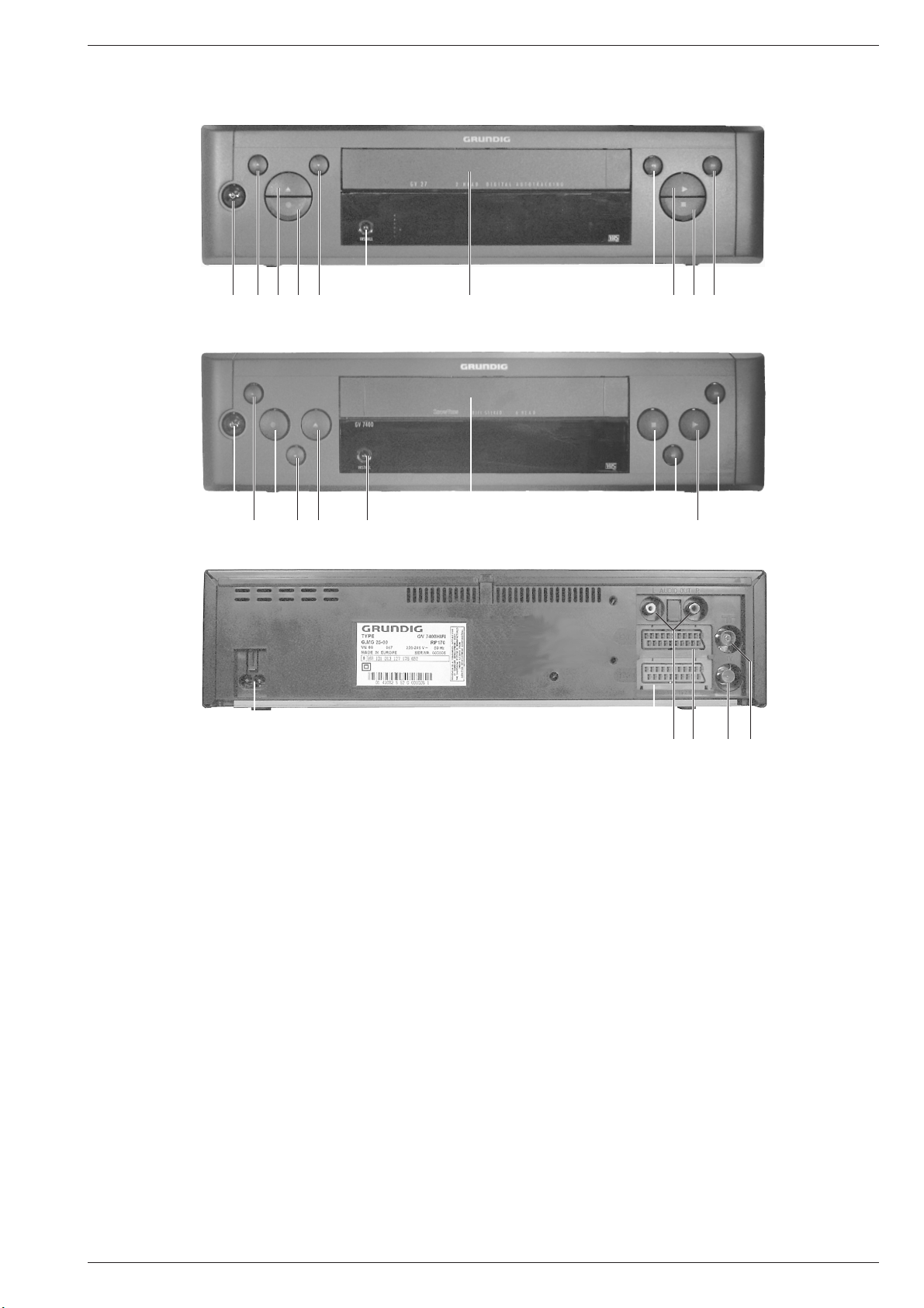
Operating Elements on the Video RecorderBedienelemente des Videorecorders
12345 6 7 890!
124 53 6 7 0 8 9!
@#$%^&
1 Schaltet den Videorecorder ab (Standby)
2 Zur Programmplatzwahl (bei Stop)
3 Cassettenauswurf
4 Aufnahme
5 Zur Programmplatzwahl (bei Stop)
6 Installation / ATS EURO Suchlauf
7 Cassettenfach
8 Bildsuchlauf rückwärts (bei Wiedergabe);
Rücklauf bei Stop
9 Startet die Wiedergabe
0 Pause;
Beendet alle Funktionen (Stop)
! Bildsuchlauf vorwärts (bei Wiedergabe);
Vorlauf bei Stop
@ Netzanschluß
# EURO-AV1-Buchse
$ Audioausgang
% EURO-AV2-Buchse
^ Antennenausgang
& Antenneneingang
1 Switches the recorder to standby
2 For selecting programme positions (on stop)
3 Cassette eject
4 Record
5 For selecting programme positions (on stop)
6 Installation / ATS EURO search
7 Cassette compartment
8 Reverse picture search (on playback);
rewind (on stop)
9 Starts playback
0 Pause;
Terminates all functions (stop)
! Forward picture search (on playback);
wind (on stop)
@ Mains socket
# EURO-AV1-socket
$ Audio output
% EURO-AV2-socket
^ Aerial socket output
& Aerial socket input
GRUNDIG Service 1 - 7
Allgemeiner Teil / General Section GV 27 …, GV 47 …, GV 7…
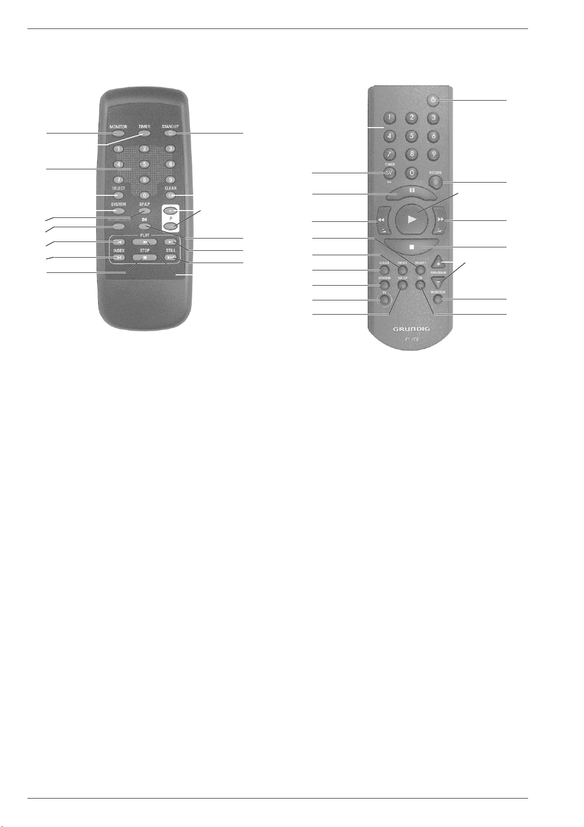
Bedienelemente der Fernbedienung
1
2
3
4
5
6
7
8
9
0
!
@
#
$
%
^
&
Operating Elements of the Remote Control
3
2
^
8
4
9
@
5
*
6
!
7
&
%
0
#
1
$
1 TV-Monitorfunktion
2 Eröffnet die Timer-Programmierung
und bestätigt Timer-Daten
3 Ziffern-Tasten für verschiedene Eingaben
4 Funktionswahl
5 Normumschaltung (ohne Funktion)
6 Schaltet auf Langspiel-Betrieb und wieder zurück auf
Standardspiel-Betrieb
7 Startet die Aufnahme
8 Bildsuchlauf rückwärts (bei Wiedergabe);
Rücklauf (bei Stop)
9 Wählt die INDEX-Such-Funktion
0 Pause;
Beendet alle Funktionen (Stop)
! Schaltet den Recorder ab (STANDBY);
aktiviert und deaktiviert die Kindersicherung (Option)
@ Löscht Daten
# Wählt den Programmplatz (bei Stop);
wählt Daten (bei der Timer-Programmierung)
$ Bestätigt Daten
% Bildsuchlauf vorwärts (bei Wiedergabe);
Vorlauf (bei Stop)
^ Standbild bei Wiedergabe
& Startet die Wiedergabe
* Fernsehgerät fernbedienen (dazu Taste TV gedrückt halten)
1
TV monitor function
2 Activates the timer programming function
and confirms timer data
3 Numbered buttons for various entries
4 Function selection
5 Standard switching (no function allocated)
6 Switches over to Long Play and back to
Standard Play
7 Starts recording function
8 Reverse picture search (on playback);
rewind (from stop)
9 Selects the INDEX search funktion
0 Pause;
Terminates all functions (stop)
! Switches the recorder off (Standby);
activates and deactivates the parental programme lock (Option)
@ Clears data
# Selects the programme position (from stop);
selects data (on timer programming)
$ Confirms data
% Forward picture search (on playback);
fast forward (from stop)
^ Freeze-frame on pla yback
& Starts playback function
* Remote control of television (press and hold down TV button)
1 - 8 GRUNDIG Service
GV 27 …, GV 47 …, GV 7… Allgemeiner Teil / General Section
Servicehinweise
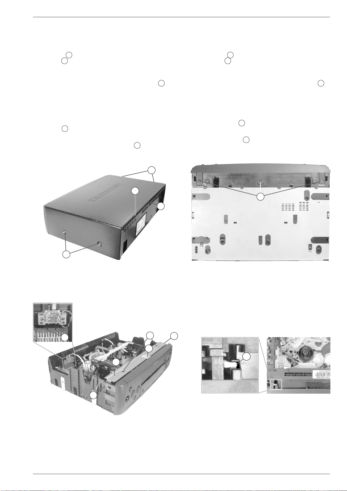
1. Entfernen der Gehäuseteile
1.1 Gehäuseoberteil
– 4 Schrauben A herausdrehen (Fig. 1).
– Rasthaken B (Fig. 1) lösen, Gehäuseoberteil hinten anheben und
1cm nach hinten schieben.
– Seitenteile des Gehäuseoberteils vorsichtig auseinanderziehen
und dabei Gehäuseoberteil abnehmen.
Montagehinweis: Das Gehäuseoberteil muß in die Rille C der
Rückwand eintauchen (Fig. 1).
1.2 Bodenblech
– Das Bodenblech darf aus Sicherheitsgründen (Massefedern durch-
trennen Leiterbahnen durch das Schieben des Bodenbleches) nicht
abgenommen werden.
1.3 Frontblende
– Rasthaken D (Fig. 2 / 3) lösen und Frontblende abnehmen.
Montagehinweis: Beim Aufstecken der Frontblende von vorne auf
das Gerät ist die Cassettenklappe so nach innen
zu drücken, daß der Hebel E in die Führung
(Fig. 4) der Cassettenklappe eintaucht.
A
C
B
Service Instructions
1. Removing the Cabinet Parts
1.1 Cabinet Upper Part
– Undo 4 screws A (Fig. 1).
– Release catch B (Fig. 1), lift the cabinet upper part on the rear edge
and push it backwards by 1cm.
– Remove the cabinet upper part by pressing its side panels carefully
apart.
Reassembly: The cabinet upper part must fit into the groove C on
the back panel (Fig. 1).
1.2 Bottom Panel
– For reasons of safety the bottom panel must not be removed (by
pushing the bottom panel the earthing springs cut the circuit tracks).
1.3 Front Panel
– Release the catches D (Fig. 2 / 3) and remove the front panel.
Reassembly: When attaching the front panel from the front to the
video recorder press the cassette lid inwards so that
the lever E engages with the guide (Fig. 4) of the
cassette lid.
D
S
siehe Punkt 1.2
see para 1.2
A
Fig. 1
H
F
D
D
Fig. 2
E
G
D
Fig. 3
Fig. 4
GRUNDIG Service 1 - 9
Allgemeiner Teil / General Section GV 27 …, GV 47 …, GV 7…
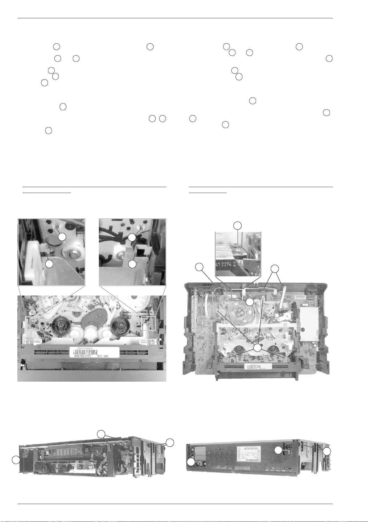
2. Ausbauhinweise
2.1 Chassisplatte mit Laufwerk ausbauen
– 2 Schrauben F (Fig. 3) herausdrehen und den Bügel G nach
oben abziehen.
– Arretierungen R und S (Fig. 5) des Cassettenschachtes lösen
und diesen dabei so weit nach innen schieben, bis die vorderen 2
Schrauben U (Fig. 6) zugänglich sind.
– 4 Schrauben U (Fig. 6) herausdrehen.
– 3 Kabel K (Fig. 6) aus den Haltern der Geräterückseite nehmen
und frei legen.
– Line-Buchsen-Platte (Option) ausbauen:
– Steckverbindungen zur Line-Buchsen-Platte lösen.
– 2 Rasthaken H (Fig. 3) lösen und die Line-Buchsen-Platte
herausziehen.
– Gerät auf die Oberseite legen (Fig. 7 / 8) und 10 Rasthaken I /
lösen (jede Seite von hinten nach vorne).
– Rastnase J (Fig. 8) nochmals lösen.
– Gehäuserahmen vorsichtig abnehmen.
Sicherheitshinweis:
– Nach dem Entfernen des Gehäuserahmens ist die Lötseite des
Netzteils frei zugänglich und damit auch alle lebensgefährlichen
Spannungen. Im Servicefall immer Trenntrafo benutzen!
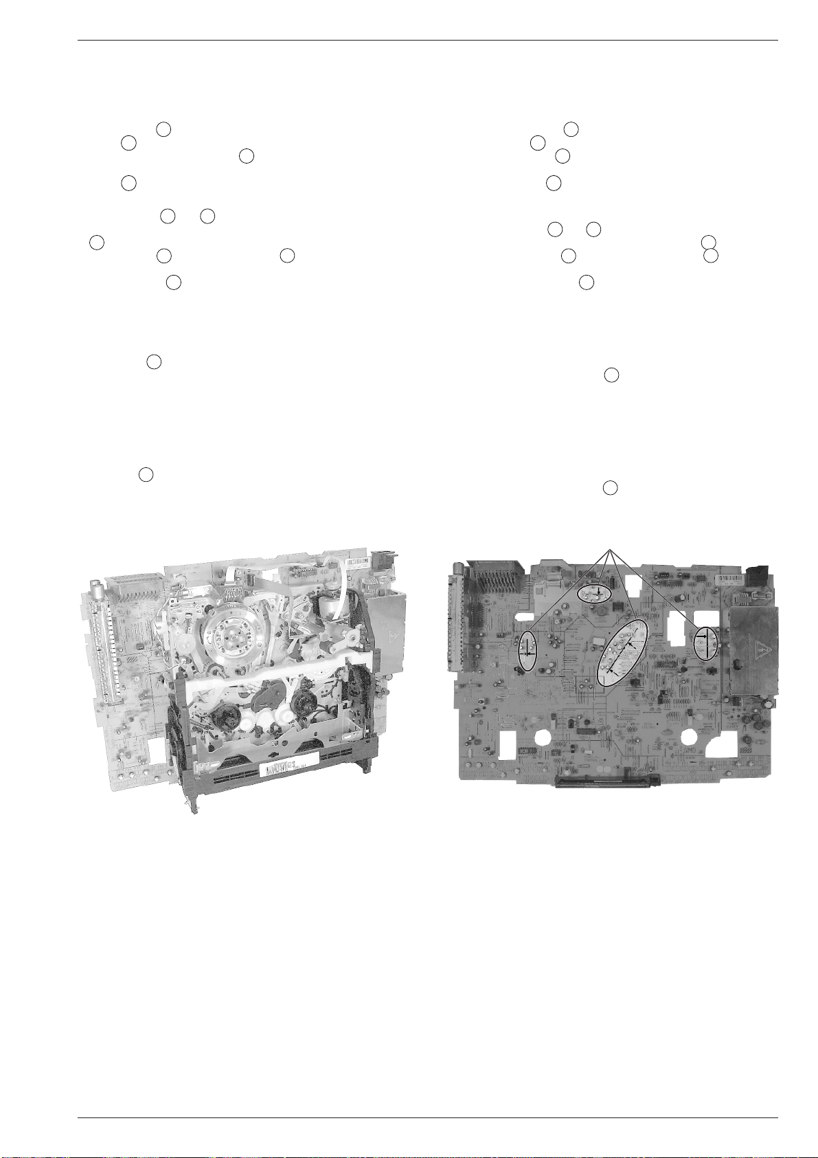
Servicestellung:
– Chassisplatte mit Laufwerk wie in Fig. 9 gezeigt aufstellen.
Achtung: Nicht die Cassetten-Ausgabe-Taste drücken und keinen
Abgleich durchführen.
2. Disassembly Instructions
2.1 Removing the Chassis Board with Mechanics
– Undo 2 screws F (Fig. 3) and raise the bracket G to remove it.
– Release the locks R and S (Fig. 5) of the cassette compartment
and move it inwards to gain access to the two front screws
(Fig. 6).
– Undo the 4 screws U (Fig. 6).
– Release the 3 cables K (Fig. 6) from their holders on the rear side
of the cabinet so that they are free.
– Remove the Line socket board (option):
– Unplug the connections to the Line socket board.
– Disengage the 2 catches H (Fig. 3) and pull out the Line socket
board.
J
– Put the VCR upside down (Fig. 7/8) and release the 10 catches I/
J
(from the back to the front on each side).
– Release catch J (Fig. 8) again.
– Remove the cabinet frame carefully.
Safety Precaution:
– After having removed the cabinet frame the solder side of the Power
Supply Board is freely accessible and with it all voltages dangerous
to life. Do not forget to use an isolating transformer during repairs!
Service Position:
– Place the Chassis Board with the Drive Mechanism in vertical
position as shown in Fig. 9.
Warning: Do not press the cassette eject button and do not carry out
any adjustments.
U
T
Y
R
Fig. 5 Fig. 6
Y
S
K
W
K
U
I
I
J
I
Fig. 7 Fig. 8
1 - 10 GRUNDIG Service
I
I
GV 27 …, GV 47 …, GV 7… Allgemeiner Teil / General Section
Einbauhinweis:
– Chassisplatte mit Laufwerk (nur seitlich am Cassettenschacht
anfassen) so in den Gehäuserahmen legen, daß die Netzteilbuchse und die EURO-AV-Buchsen in den dafür vorgesehenen
Führungen sind. Alle 10 Rasthaken müssen dabei einrasten.
– 4 Schrauben U (Fig. 6) hineindrehen.
– Bügel G wie in Fig. 3 dargestellt auf den Gehäuserahmen stek-
ken und mit den 2 Schrauben F befestigen.
– Line-Buchsen-Platte (Option) einbauen und wieder anschließen.
– Kabel K (Fig. 6) in den Haltern der Geräterückseite einlegen.
2.2 Laufwerkausbau
– Arretierungen R und S (Fig. 5) des Cassettenschachtes lösen
und diesen dabei so weit nach innen schieben, bis die Schrauben
U
(Fig. 6) zugänglich sind.
– 4 Schrauben U und Masseschraube T (über die Bohrung der
Geräterückwand zugänglich) herausdrehen (Fig. 6).
– Abschirmblech W (Fig. 6) nach hinten biegen.
– 5 Steckverbindungen vom Laufwerk (Kopfscheibe, Löschkopf,
Kombikopf und Fädelmotor) zur Chassisplatte lösen.
– Laufwerk an der Geräterückseite vorsichtig etwas anheben, damit
sich die Steckverbindung 1946 zwischen dem Laufwerk und der
Chassisplatte löst.
– Rastnasen Y (Fig. 5) lösen und Laufwerk aus dem Gerät neh-
men.
Einbauhinweis:
– In die markierten Bereiche der Chassisplatte (Fig. 10) dürfen keine
Bauteile hineinragen. Die Bauteile (Kondensatoren) sind entspre-
chend der Pfeile auszurichten.
– Nach dem Einbau des Laufwerks ist die Masseverbindung zwi-
schen Chassisplatte und Laufwerk durch Eindrehen der Masse-
schraube T (Fig. 6) herzustellen.
Fitting Instructions:
– Put the Chassis Board together with the Drive Mechanism (take it
only by the side of the cassette compartment) into the cabinet frame
so that the mains socket and the EURO-AV sockets are in their
appropriate guides. All 10 catches must lock in.
– Tighten the 4 screws U (Fig. 6).
– Attach bracket G to the cabinet frame as shown in Fig. 3 and fasten
it with the 2 screws F.
– Re-fit the Line socket board (option) and re-connect it.
– Fasten the cables K (Fig. 6) with the holders on the rear side of the
cabinet.
2.2 Removing the Drive Mechanism
– Release the locks R and S (Fig. 5) of the cassette compartment
and move it inwards to gain access to the screws U (Fig. 6).
– Undo the 4 screws U and the earthing screw T (accessible
through the hole of the cabinet rear side) (Fig. 6).
– Push the shielding plate W (Fig. 6) to the rear.
– Disconnect the 5 plug-in connections from the Drive Mechanism
(headwheel, erase head, combi-head and threading motor) to the
Chassis Board.
– Lift the Drive Mechanism on the rear side carefully by a small amount
to disengage the plug-in connection 1946 between the Drive Mecha-
nism and the Chassis Board.
– Disengage the locking lugs Y (Fig. 5) and remove the Drive
Mechanism.
Fitting Instructions:
– Ensure that no components reach into the marked areas on the
Chassis Board (Fig. 10). Position the components (capacitors) as
shown by the arrows.
– After having re-fitted the Drive Mechanism, re-establish the chassis
connection between the Chassis Board and the Drive Mechanism by
tightening the earthing screw T (Fig. 6).
Fig. 9 Fig. 10
3. Wichtige Masseverbindungen!
Beim Zusammenbau des Gerätes ist darauf zu achten, daß die
Masseverbindungen zwischen Gehäuseboden und Chassisplatte,
Chassisplatte und Laufwerk sowie Gehäuseboden und Gehäuseoberteil gewährleistet sind.
siehe Punkt 2.2
see para 2.2
3. WARNING: Chassis Connections!
When reassembling the machine it is essential to observe that the
chassis connections between the cabinet bottom and Chassis Board,
Chassis Board and Drive Mechanism, cabinet bottom and cabinet
upper part are in good order.
4. Durchführen von Messungen
Bei Messungen mit dem Oszilloskop an Halbleitern sollten Sie nur
Tastköpfe mit 10:1 - Teiler verwenden. Außerdem ist zu beachten, daß
nach vorheriger Messung mit AC-Kopplung der Koppelkondensator
des Oszilloskops aufgeladen sein kann. Durch die Entladung über das
Meßobjekt können diese Bauteile beschädigt werden.
5. Meßwerte und Oszillogramme
Bei den in den Schaltplänen und Oszillogrammen angegebenen
Meßwerten handelt es sich um Näherungswerte!
GRUNDIG Service 1 - 11
4. Carrying out Measurements
When making measurements on semi-conductors with an oscilloscope, ensure that the test probe is set to 10:1 dividing factor. Further,
please note that if the previous measurement is made on AC input, the
coupling capacitor in the oscilloscope will be charged. Discharge via
the item being checked can damage components.
5. Measured Values and Oscillograms
The measured values given in the circuit diagrams and oscillograms
are approximates!
Allgemeiner Teil / General Section GV 27 …, GV 47 …, GV 7…
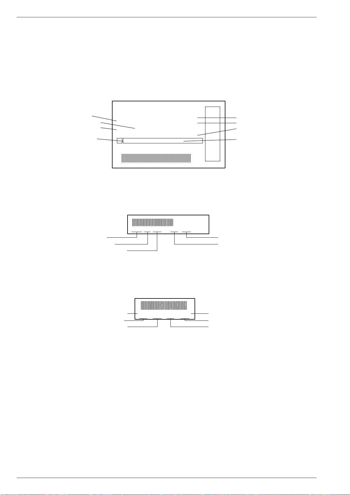
6. Codeaufkleber
Alle wichtigen Komponenten des Gerätes (Laufwerk / Platinen) sind
mit einem Codeaufkleber versehen. Diese Aufkleber beinhalten die
Typenbezeichnung und Produktionsdaten (Seriennummer, Produktionscode, Produktionsdatum, …).
Typenschild des Gerätes
Technische Weiterentwicklungen oder Änderungen sind wie folgt auf
dem Typenschild ersichtlich:
• Produktionscode – geringfügige Änderungen
• Entwicklungscode – gravierende Änderungen
1
Bestellnummer / Order number
Produktionsdatum / Production date
Produktionscode / Production code
Entwicklungscode / Evolution code
Laufwerks-Codeaufkleber
Hinweis:
Der Produktionscode und die Seriennummer auf dem Codeaufkleber
des Laufwerks müssen nicht mit dem Produktionscode und der Seriennummer auf dem Typenschild übereinstimmen.
TYPE
G.MG 25-00
VN 99 067
MADE IN EUROPE
S AA XXX XXX XXX XXX XXX
A
01 40393 5 52 0 100647 1
6. Code Labels
All important components of the video recorder (drive mechanism /
printed circuit boards) are provided with a code label. These adhesive
labels indicate the type of product and the production data (serial
number, production code, date of production, …).
Type Plate of the Set
Technical advance developments or changes are to be seen from the
type plate as follows:
• Production code – minor changes
• Evolution code – important changes
GV 7400 HIFI
RP 170
220-240V ~ 50Hz
SER.NR. 100647
UNDER LICENSE FROM
BY GEMSTAR DEVELOPMENT CORP.
GEMSTAR DEVELOPMENT CORPORATION
SHOW VIEW SYSTEMS IS MANUFACTURED
SHOW VIEW IS A TRADEMARK APPLIED FOR
Code Label on the Drive Mechanism
Advice:
The production code and the serial number on the code label of the
drive mechanism do not necessarily agree with the production code
and the serial number on the type plate.
Gerätetype / Type of product
Fernbedienung / Remote control
Seriennummer / Serial number
Geräte-Optionscode / Option code
10051442587303
25873030 10051 Q-P 4/2 971521 11WD44
Seriennummer / Serial number
Fabrikcode / Factory code number
Laufwerkstype / Type of drive mechanism
Platinen-Codeaufkleber
Hinweis:
Der Produktionscode ist nicht generell aufgedruckt. Bei wichtigen
Änderungen erhöht sich die letzte Ziffer der Fabrikscodenummer
(Punktnummer).
Platinenbezeichnung / Name of PCB
Fabrikcode / Factory code number
Produktionsdatum / Production date
QGD675021 27599-010.55
82162 KW724 WD01 123456
Produktionscode / Production code
Produktionsdatum / Production date
Code Label on the Printed Circuit Boards
Advice:
The production code is not generally printed on the label. Important
changes are indicated by increasing the last figure of the factory code
by one (figure following the point).
Sach-Nummer / Part number
Seriennummer / Serial number
Produktionscode / Production code
1 - 12 GRUNDIG Service
GV 27 …, GV 47 …, GV 7… Servicetestprogramm & Sonderfunktionen
– Laufwerkstellung und Funktion des Init Schalters.
Servicetestprogramm & Sonderfunktionen
Das Diagramm zeigt die Funktion des Init-Schalters in Abhängigkeit
von der Stellung des Laufwerks. Dafür ist die Anzahl der Fädeltacho-
impulse (FTA) wichtig. Diese Impulse erzeugt der Fädeltachogeber
1. Servicetestprogramm
Aufruf, Ebenenkontrolle und Beenden des Servicetestprogrammes
Der Aufruf des Servicetestprogrammes ist bei allen Laufwerksfunktionen
(Flügelrad), der mechanisch mit dem Fädelmotor verbunden ist.
DC, 2V/Div, 0,5s/Div
Init Schalter
möglich, jedoch nicht während der Einstellfunktionen (Sendersuchlauf, …). Während des Servicemodes bleibt das Gerät bei allen
Laufwerksfunktionen voll einsatzbereit.
• Aufruf des Servicetestprogrammes
Die Tasten ■(STOP) auf der Fernbedienung und e(Wiedergabe)
am Gerät in dieser Reihenfolge drücken und für mindestens 5s
Cassette eingeschoben
Cassette unten Index, Umspulen
Fädeltacho-Impuls (FTA)
Wiedergabe rückwärts
Wiedergabe
gedrückt halten.
Im Display erscheinen anschließend die Werte der Ebene 00.
• Ebenenkontrolle des Servicetestprogrammes
Das Servicetestprogramm besteht aus folgenden Ebenen:
Ebene 00 – Masken-Nr. des Laufwerk- und Bedienrechners
Ebene 01 – Laufwerkstellung
Ebene 02 – Fehlercode und Fehlerstatus / Gerätefunktion
Ebene 03 – man. Tracking, Laufwerksensoren und Gerätefunktion
Ebene 04 – Betriebsstundenzähler
Ebene 10 – Laufwerksensoren und Gerätefunktion ohne Laufwerk-
ansteuerung
Ebene 40 – Geräte-Optionscodes
Ebene 02: Fehlercode und Fehlerstatus / Gerätefunktion
Der zuletzt aufgetretene Fehlerstatus und Fehlercode wird im EEPROM
gespeichert und bleibt auch dann erhalten, wenn das Gerät vom Netz
getrennt wird. Löschen kann man diese durch Drücken der Taste
"CLEAR" auf dem Fernbediengeber.
Fehlercode
0 Kein Fehler
1 Fädelfehler
2 Kein Capstantacho
3 Band gerissen
4 Kein Wickeltacho links (Option)
5 Kein Wickeltacho rechts
6 Kopfscheibenmotorfehler
Ebene 51 – Kopfscheibenlagengeber-Abgleich
Ebene 52 – ACC-Abgleich (Automatic Contour Control, optional)
Ebene 53 – Uhr-Takt-Abgleich
Ebene 60 – Audio-Pegeleinstellung des IC7780 (FV)
Ebene 61 – Audio-Kanaltrennung des IC7780 (FV)
Ebene 62 – Standardton-Wiedergabepegel des IC7850 (AF)
Ebene 99 – Uhr-Takt-Ausgabe
Ebenenanwahl
– Vor der Anwahl der Abgleich-Ebenen (51…62) ist auf die Vorbe-
reitung der jeweiligen Ebene zu achten (siehe die folgende
Beschreibung zu der jeweiligen Ebene des Servicetestprogrammes).
– Taste "SELECT" auf der Fernbedienung drücken. Im Display
blinkt die Ebenenanzeige.
– Mit der Taste "+" oder "–" auf die entsprechende Ebene weiter-
schalten oder mit den Tasten "0…9" die gewünschte Ebene direkt
anwählen.
– Mit der Taste "SELECT" die Eingabe bestätigen.
Bei der Anwahl einer nicht belegten Ebene blinkt im Display "--".
• Beenden des Servicetestprogrammes:
Taste 8 "STANDBY" drücken oder Gerät vom Netz trennen.
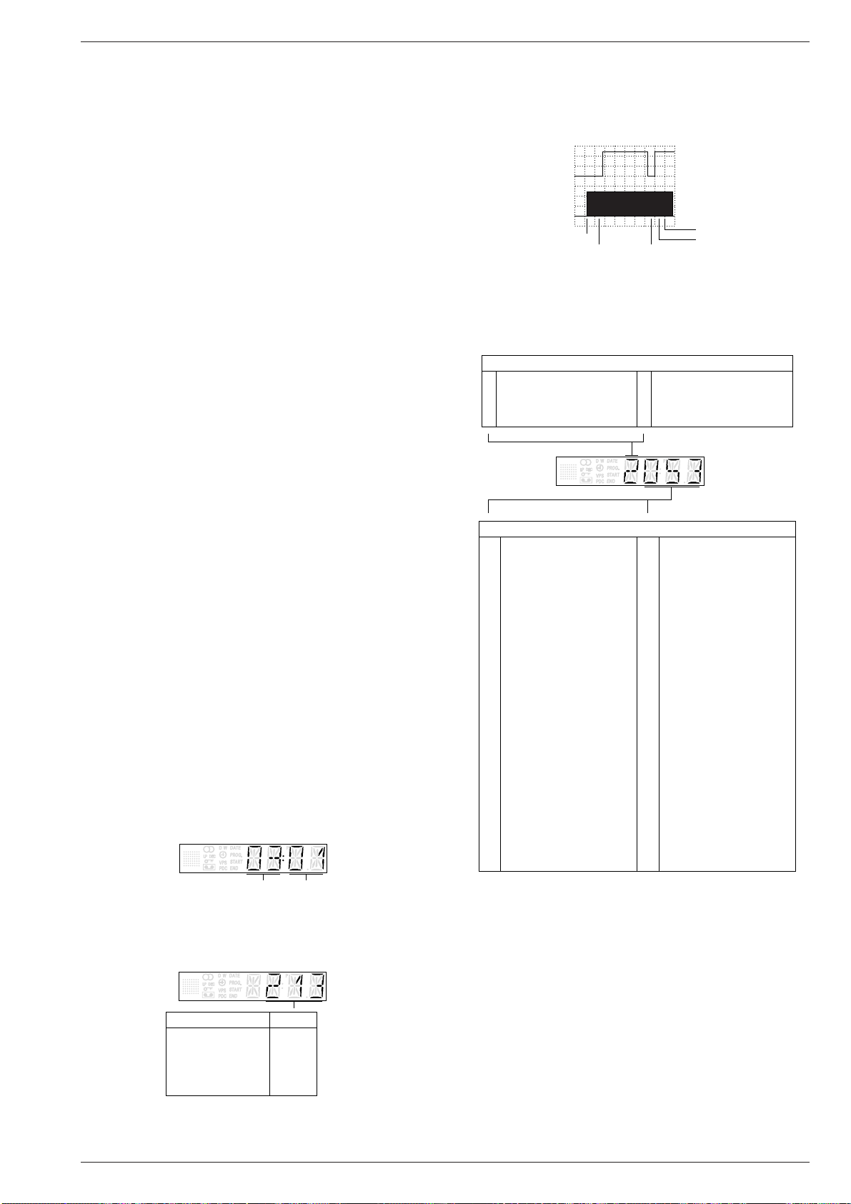
Ebenen des Servicetestprogrammes
Ebene 00: Masken-Nr. der Laufwerk- und Bedienrechner
Die Maskennummern der einzelnen Rechner werden wie folgt angezeigt.
Fehlerstatus / Gerätefunktion
012 Bereitschaft
014 Tracking
031 Bildsuchlauf rückwärts (3-fach)
034 Zeitlupe rückwärts
041 Standbild
042 Bildsuchlauf vorwärts (3-fach)
044 Bildsuchlauf rückwärts (9-fach)
045 Ausfädeln
046 Bildsuchlauf vorwärts (9-fach)
047 Wiedergabe rückwärts
048 Aufnahme – Pause
050 Rücklauf
052 Vorlauf
053 Wiedergabe
054 Stop
055 Aufnahme
112 Nächster Index
113 Vorheriger Index
114 VISS-Marke schreiben
115 VISS-Marke löschen
125 Tuner
126 Auto Remain
130 ATTS
168 Einzelbildfortschaltung +
169 Einzelbildfortschaltung –
170 Bildsuchlauf rückwärts (11-fach)
171 Bildsuchlauf rückwärts (7-fach)
172 Bildsuchlauf rückwärts (5-fach)
173 Bildsuchlauf vorwärts (5-fach)
174 Bildsuchlauf vorwärts (7-fach)
175 Bildsuchlauf vorwärts (11-fach)
196 EE-Betrieb
197 Bereitschaft - Schacht oben
199 Nachvertonung
202 Nachvertonung – Pause
206 Bandlängenzählwerk löschen
211 Zeitlupe (1/24)
212 Zeitlupe (1/14)
215 Zeitlupe (1/7)
216 Zeitlupe (1/2)
217 Zeitlupe rückwärts (1/24)
218 Zeitlupe rückwärts (1/14)
219 Zeitlupe rückwärts (1/7)
220 Zeitlupe rückwärts (1/2)
222 Sychro-Edit-Aufnahme
223
Kopfscheibenlagengeberabgleich
238 Pause
239 ACC-Abgleich
246 Synchro-Edit-Pause
247 Zeitlupe (1/10)
248 Zeitlupe (1/18)
249 Zeitlupe rückwärts (1/10)
250 Zeitlupe rückwärts (1/18)
253 Tastenfreigabe
Laufwerkrechner Bedienrechner
Ebene 01: Laufwerkstellung
Der Code für die Laufwerkstellung gibt die Positionen des Cassettenschachts und der Fädelschlitten an.
– Überwachung der Laufwerkfunktionen
Das Laufwerk wird mit Sensoren überwacht. Diese liefern entsprechend der Gerätefunktion folgende Tachosignale:
– WTR – Wickelteller rechts
– WTL – Wickelteller links (Option)
– FTA – Fädeltacho
– FG – Capstanmotor
– PG/FG – Kopfscheibenmotor.
Fehlt bei der Ansteuerung des Laufwerks ein Tachosignal, dann
Laufwerkstellung Code
Auswurf 005…009
Index 189…191
Ausgefädelt-Stop 196…204
Wiedergabe 209…217
Wiedergabe rückwärts 237…239
GRUNDIG Service 2 - 1
versucht das Gerät, den Cassettenschacht in die Stellung "EJECT"
zu bringen.
j
Servicetestprogramm & Sonderfunktionen GV 27 …, GV 47 …, GV 7…
,
Ebene 03: man. Tracking, Laufwerksensoren und Gerätefunktion
– Manuelles Tracking
Die Trackinglage ist im Servicetestprogramm in der Mittelposition.
Durch das Betätigen der "+" oder "–" -Tasten ist die Verschiebung
der Trackinglage in die erforderliche Position für die Bandlaufeinstellung (s. Kap. 5 – Laufwerk) möglich.
– Laufwerksensoren
Zur Kontrolle der Laufwerksensoren (Init Schalter, Fädeltacho,
Bandanfang, Bandende, Aufnahmesperre, Wickeltacho Links /
Rechts) werden auf dem Display die Betriebszustände mit einer
Digitalstelle angezeigt. Mit jeder Betätigung der Sensoren ändern
sich die Werte der Anzeige.
– Gerätefunktion
Die Symbole ( ■ ● r e ) für die Gerätefunktion geben die Position
des Cassettenschachts und der Fädelschlitten an.
Gerätefunktion
Fädeltacho (FTA)
Init-Schalter (INIT)
Aufnahmesperre (RECP)
Bandende
Wickeltacho links (Option)
Bandanfang
Wickeltacho rechts
Ebene 04: Betriebsstundenzähler
Der Betriebsstundenzähler gibt die Betriebsstunden der Kopfscheibe
an.
Ebene 10: Laufwerksensoren und Gerätefunktion
ohne Laufwerkansteuerung
In dieser Ebene werden die Laufwerksensoren im Display angezeigt,
wie in der Ebene 03 erklärt. Des weiteren sind die Gerätefunktionen
anwählbar und für die Fehlersuche (ohne Laufwerk) werden die
entsprechenden Signalwege freigeschaltet.
In dieser Ebene erfolgt keine Ansteuerung des Laufwerks.
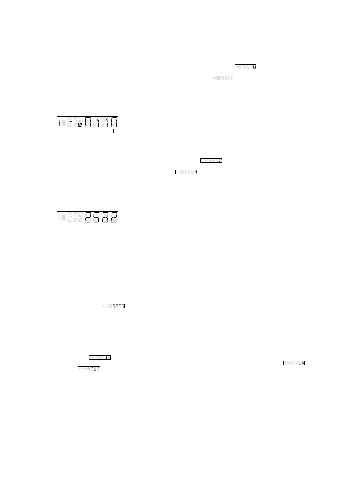
Ebene 40: Geräte-Optionscodes
Mit dem Geräte-Optionscode "A"…"E" wird gemäß dem Geräteaufbau
die entsprechende Software in den maskenprogrammierten µCs aktiviert. Der Optionscode wird im EEPROM gespeichert.
– Im Display erscheint nach dem Aufruf der Ebene 40 die Eingabe-
aufforderung für den Optionscode "A" ( ).
– Gewünschten Optionscode "A"…"E" mit den Tasten "–" oder "+"
anwählen.
– Eingabe der Optionscodes am Beispiel für Optionscode "A":
– Optionscode "A", siehe Geräte-Typenschild (z.B. "191") mit der
Fernbedienung eingeben.
Achtung: Nur bei richtiger Optionscode-Eingabe sind alle
Gerätefunktionen gewährleistet.
– Eingabecode mit der Taste "OK" bestätigen.
Im Display erscheint für ca. 3s . Anschließend schaltet
das Gerät automatisch zur Eingabeaufforderung zurück und zeigt
den gespeicherten Wert .
– Die Eingabeschritte der Optionscodes "B"…"E" sind genauso
durchzuführen wie bei dem Optionscode "A".
– Kontrolle der Optionscodes:
– Durch Betätigen der Tasten "–" oder "+" ohne vorheriger Options-
code-Eingabe ist die Kontrolle der die Optionscodes "A"…"E"
möglich.
Ebene 51: Kopfscheibenlagengeber-Abgleich
Der Kopfscheibenlagengeber-Abgleich ist nach dem Austausch der
Kopfscheibe oder des EEPROMs (IC7890) durchzuführen.
Vorbereitung vor dem Aufruf dieser Ebene:
– Testcassette wiedergeben.
Dieser Abgleich erfolgt nach dem Aufruf automatisch. Während dem
Abgleich zeigt das Display . Der Abgleichwert wird nach
erfolgreich durchgeführtem Abgleich im EEPROM gespeichert. Im
Display erscheint .
Bei nicht erfolgreich durchgeführtem Abgleich gibt das Gerät die
Cassette aus und verläßt das Servicetestprogramm. Ursache: Testcassette, Kopfscheibe oder technischer Defekt (z.B. µC)
Ebene 52: ACC-Abgleich (Automatic Contour Control, optional)
Der ACC-Abgleich ist nach dem Austausch der Kopfscheibe oder des
EEPROMs (IC7890) durchzuführen.
Vorbereitung vor dem Aufruf dieser Ebene:
– Schwarztestbild ohne Burst an der EURO-AV1-Buchse einspeisen
– Aufnahme- / Wiedergabe-Cassette wiedergeben.
Dieser Abgleich erfolgt nach dem Aufruf automatisch
(15s eine Aufnahme in den Betriebsarten SP/LP und bei der Wiedergabe dieser
Aufnahme wird das Gerät abgeglichen)
. Während dem Abgleich zeigt
das Display . Der Abgleichwert wird nach erfolgreich durchgeführtem Abgleich im EEPROM gespeichert. Im Display erscheint
.
Bei nicht erfolgreich durchgeführtem Abgleich gibt das Gerät die
Cassette aus. Ursache: Vorbereitung, Cassette, Kopfscheibe oder
technischer Defekt (z.B. µC)
Ebene 53: Uhr-Takt-Abgleich
Vorbereitung vor dem Aufruf dieser Ebene:
– Ebene 99 – Uhr-Takt-Ausgabe durchführen und Meßwert (f
notieren.
mess
– Ermittlung des Korrekturwertes:
f
= gemessene Frequenz
mess
f
= Sollfrequenz (2048,0000Hz)
soll
Abweichung =
Korrekturwert = +128
1 x 10⁶ x (f
Abweichung
0,763
f
mess
soll
– f
soll
)
Beispiel:
f
= 2047,9700Hz
mess
f
= 2048,0000Hz
soll
-14,648 =
108,80 = +128
1 x 106 x (2047,97Hz – 2048Hz)
2048Hz
-14,648
0
763
Korrekturwert gerundet für Eingabe: 109
Liegt der errechnete Korrekturwert außerhalb des Bereiches 0…255
ist ein technischer Defekt des Quarzes Q1297 möglich.
Eingabe des Korrekturwertes
– Im Display erscheint nach dem Aufruf der Ebene 53 der im Gerät
aktuelle Korrekturwert "0"…"255".
– Korrekturwert (gerundet) eingeben und mit der Taste "OK" bestäti-
gen. Im Display erscheint zur Kontrolle für ca. 3s .
)
2 - 2 GRUNDIG Service
j

GV 27 …, GV 47 …, GV 7… Servicetestprogramm & Sonderfunktionen
Ebene 60: Audio-Pegeleinstellung des IC7780 (FV, Option)
Die Audio-Pegeleinstellung ist nach dem Austausch des Stereodecoders (IC7780) oder des EEPROMs (IC7890) durchzuführen.
Vorbereitung vor dem Aufruf dieser Ebene:
– NF-Millivoltmeter an der EURO-AV1-Buchse, Kontakt 1 anschlie-
ßen
– Weißtestbild mit Tonträger (Tonmodulation "Stereo", rechter Kanal
1kHz Sinus, ±27kHz Hub) an der Antenneneingangsbuchse einspeisen
– EE-Betrieb.
Nach dem Aufruf der Ebene 60 erscheint der aktuelle Einstellwert
"0"…"9". Der Ausgangspegel ist mit den Tasten "–" oder "+" auf
500mV
Pegeländerung von 0,5dB und der Einstellwert wird im EEPROM
abgelegt.
Ebene 61: Audio-Kanaltrennung des IC7780 (FV, Option)
Die Audio-Kanaltrennung ist nach dem Austausch des Stereodecoders
(IC7780) oder des EEPROMs (IC7890) durchzuführen.
Vorbereitung vor dem Aufruf dieser Ebene:
– NF-Millivoltmeter an der EURO-AV1-Buchse, Kontakt 3 (linker
– Weißtestbild mit Tonträger (Tonmodulation "Stereo", rechter Kanal
– EE-Betrieb.
Nach dem Aufruf der Ebene 61 erscheint der aktuelle Einstellwert
"0"…"49". Die Rauschspannung des linken Kanals ist mit den Tasten
"–" oder "+" auf Minimum einzustellen. Dabei erfolgt pro Tastendruck
eine Pegeländerung von 0,1dB und der Einstellwert wird im EEPROM
abgelegt.
Ebene 62: Standardton-Wiedergabepegel des IC7850 (AF, Option)
Der Standardton-Wiedergabepegel ist nach dem Austausch des IC7850
oder des EEPROMs (IC7890) durchzuführen.
Vorbereitung vor dem Aufruf dieser Ebene:
– NF-Millivoltmeter an der EURO-AV1-Buchse, Kontakt 1 anschließen
– Tonsignal (1kHz Sinus, 0,7V
– FBAS-Signal an der EURO-AV1-Buchse einspeisen
– Tonsignal aufnehmen.
Nach dem Aufruf der Ebene 62 erscheint der aktuelle Einstellwert
"0"…"15". Das aufgenommene Tonsignal ist wiederzugeben (Standardton-Wiedergabe) und der Ausgangspegel mit den Tasten "–" oder "+"
auf 500mV
Pegeländerung von 1dB und der Einstellwert wird im EEPROM abgelegt.
Ebene 99: Uhr-Takt-Ausgabe
Für den Uhr-Takt-Abgleich (Ebene 53) ist in dieser Ebene die UhrOszillatorfrequenz (ca. 2048Hz) an IC7201-(80) "HEST" der
Bedieneinheit (DC) zu messen (Auflösung mindestens 6 Stellen) und
notieren (f
Hinweis:
Nach der Anwahl dieser Ebene ist das Display dunkel und keine
Funktion am Gerät möglich. Das Verlassen dieser Ebene und des
Servicetestprogrammes ist nur durch das Trennen des Gerätes vom
Netz möglich.
±50mV einzustellen. Dabei erfolgt pro Tastendruck eine
eff
Kanal) anschließen
1kHz Sinus, ±27kHz Hub) an der Antenneneingangsbuchse ein-
speisen
) an der EURO-AV1-Buchse, Kontak-
te 2 und 6 einspeisen
±50mV einzustellen. Dabei erfolgt pro Tastendruck eine
eff
).
mess
eff
2. Sonderfunktionen
Dauerlaufprüfung
Die Aufnahme- oder Wiedergabe-Dauerlaufprüfung ist im Servicetestprogramm integriert. Diese hilft Fehler zu finden, die sporadisch
auftreten. Ein erkannter Fehler wird im EEPROM gespeichert und
bleibt erhalten, wenn das Gerät vom Netz getrennt wird.
Aufruf der Dauerlaufprüfung
– Dauerlaufprüfung starten mit einer der Tasten ●(Aufnahme)
oder e(Wiedergabe).
Beenden der Dauerlaufprüfung
– Taste ■(STOP) oder 8 "STANDBY" drücken.
Reinigung der Kopfscheibe
Beim Einfädeln des Videobandes werden die Videoköpfe nur kurzzeitig gereinigt. Im Wiedergabebetrieb kann diese Funktion durch Drükken der Taste e(mindestens 5s) für ca. 10s aktiviert werden. Dabei
wird der Bandvorschub gestoppt und die Videokopfreinigungsrolle an
die Kopfscheibe gedrückt. Anschließend wird die Wiedergabe wieder
fortgesetzt.
RAM und EEPROM löschen
Am Gerät die Taste 8 "STANDBY" drücken und nach dem Anschließen des Gerätes an das Netz für mindestens 5s gedrückt halten.
Das EEPROM und das interne Prozessor-RAM werden gelöscht und
initialisiert. Dabei werden der kundenspezifische Senderspeicher und
die Timer-Daten gelöscht. Die gerätespezifischen Daten, Laufwerkparameter, Geräte-Optionscodes und die Abgleichwerte bleiben erhalten.
Tausch des EEPROMs IC7890
Achtung: Nach dem Tausch des EEPROMs, IC7890, müssen die
Geräte-Optionscodes der Ebene 40 eingegeben werden.
Des weiteren sind die Software-Abgleiche der Ebenen 51,
52, 53, 60, 61 und 62 durchzuführen.
Data-Programmer "IDP2"
Hinweis: Die Übertragung der im Data-Programmer gespeicherten
Sendereinstellungen ist nur über den VCR1-Mode möglich.
– Taste "EJECT" drücken (eingelegte Cassette ausgeben).
– Die Tasten ■(STOP) auf der Fernbedienung und "INSTALL" am
Gerät in dieser Reihenfolge drücken und für mindestens 5s gedrückt
halten. Im Display erscheint anschließend "MENU".
– Sendereinstellungen mit dem Data-Programmer "IDP2" übertragen
(siehe Bedienungsanleitung "IDP2").
– Am Ende der Übertragung Taste 8 "STANDBY" drücken.
GRUNDIG Service 2 - 3
j
Service Test Programme & Special Functions GV 27 …, GV 47 …, GV 7…
– Tape deck position and function of the Init switch
Service Test Programme & Special Functions
The diagram shows the function of the Init switch dependent on the
tape deck position. For this, the number of the threading tacho
pulses (FTA) is important. These signals are generated by the
1. Service Test Programme
threading tacho generator (butterfly sensor) which is mechanically
connected with the threading motor.
Calling up, Checking the Levels of and Terminating the Service Test
Programme
The service test programme can be called from any tape drive function
DC, 2V/Div, 0.5s/Div
Init switch
other than the data entry functions (station search, …). While it is
operating in the service mode, the VCR remains fully operational in all
tape drive functions.
• Calling up the Service Test Programme
Press the ■(STOP) button on the remote control and the e(Play)
button on the video recorder in that order and hold them down for at
Cassette in
Cassette down
Threading pulse (FTA)
Play reverse
Index, wind-rewind
Play
least 5 seconds.
The display will then show the values of Level 00.
• Checking the Levels of the Service Test Programme
The service test programme is made up of the following levels:
Level 00 – mask no. of the tape deck and keyboard control computer
Level 01 – tape deck position
Level 02 – error code and error status / VCR function
Level 03 – man. tracking, tape deck sensors and VCR function
Level 04 – operating hours meter
Level 10 – tape deck sensors and VCR function without drive to the
tape deck
Level 40 – VCR option codes
Level 02: Error Code and Error Status / VCR Function
The last error status and error code that occurred is stored in the
EEPROM and is saved even if the VCR is disconnected from the
mains. The data can be cleared by pressing the "CLEAR" button on the
remote control.
Drive Mechnism Error Code
0 No Error
1 Threading error
2 No capstan tacho
3 Tape torn
4 Missing left reel tacho (option)
5 Missing right reel tacho
6 Headwheel motor error
Level 51 – headwheel position indicator adjustment
Level 52 – ACC adjustment (Automatic Contour Control, option)
Level 53 – timer clock adjustment
Level 60 – audio level adjustment of IC7780 (FV)
Level 61 – audio channel separation of IC7780 (FV)
Level 62 – standard sound playback level of IC7850 (AF)
Level 99 – timer clock output
Level Selection
– Before selecting the adjustment levels (51…62) remember to
prepare the respective level first (see description of the individual
levels of the service test programme given below).
– Press the "SELECT" button on the remote control. The indication
of the level flashes on the display.
– With the "+" or "–" button switch over to the respective level or
select the desired level directly with the buttons "0…9".
– Confirm the entered figures with the "SELECT" button.
On selection of an unused level the indication "--" flashes on the
display.
• Terminating the Service Test Programme:
Press the 8 "STANDBY" button or disconnect the VCR from the
mains.
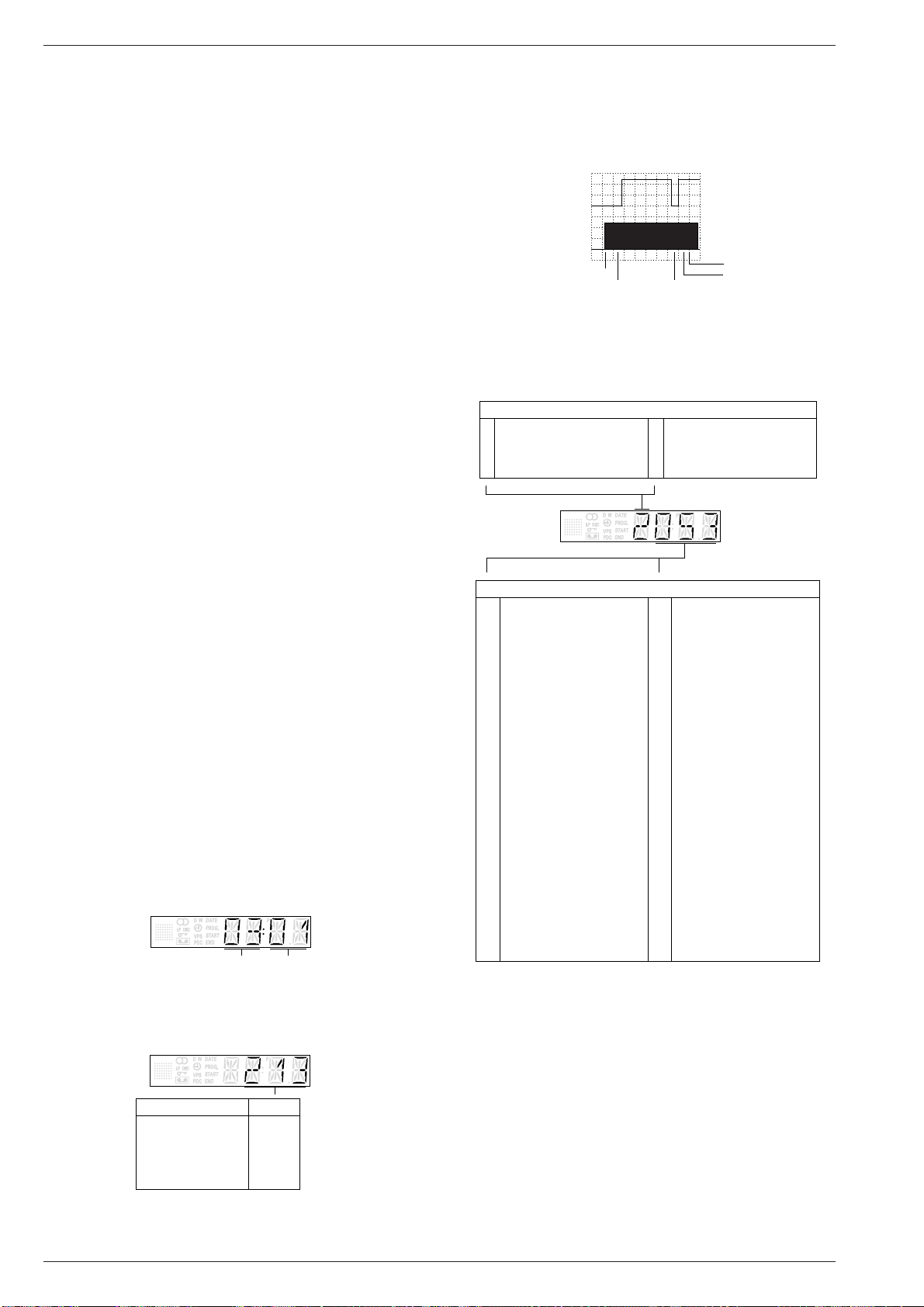
Levels of the Service Test Programme
Level 00: Mask No. of Tape Deck and Keyboard Control Computers
The mask number of the individual computers is indicated as follows:
Tape Deck Computer Keyboard Control Computer
Level 01: Tape Deck Position
The tape deck position code indicates the position of the cassette
compartment and of the threading roller units.
Drive Mechnism Error Status / VCR Function
012 Standby
014 Tracking
031 Picture search reverse (3x)
034 Slow reverse
041 Still
042 Picture search forward (3x)
044 Picture search reverse (9x)
045 Threaded out
046 Picture search forward (9x)
047 Play reverse
048 Record – Pause
050 Rewind
052 Wind
053 Play
054 Stop
055 Record
112 Next index
113 Previous index
114 Write VISS marks
115 Clearing VISS marks
125 Tuner
126 Auto Remain
130 ATTS
168 Frame forward
169 Frame reverse
170 Picture search reverse (11x)
171 Picture search reverse (7x)
172 Picture search reverse (5x)
173 Picture search forward (5x)
174 Picture search forward (7x)
175 Picture search forward (11x)
196 EE mode
197 Standby Eject
199 Audio Dubbing
202 Audio Dubbing Pause
206 Reset Tapecounter
211 Slow (1/24)
212 Slow (1/14)
215 Slow (1/7)
216 Slow (1/2)
217 Slow reverse (1/24)
218 Slow reverse (1/14)
219 Slow reverse (1/7)
220 Slow reverse (1/2)
222 Sychro-Edit-Record
223 Auto Gap Position Adjustment
238 Pause
239 ACC Adjustment
246 Synchro-Edit-Pause
247 Slow (1/10)
248 Slow (1/18)
249 Slow reverse (1/10)
250 Slow reverse (1/18)
253 Keyboard Enable
– Monitoring the tape deck functions
For monitoring the tape deck functions the tape deck is fitted with
sensors which supply the following tacho signals according to the
functions:
– WTR – reel right
– WTL – reel left (option)
– FTA – threading tacho
– FG – capstan motor
Tape Deck Positions Code
Eject 005…009
Index 189…191
Stop threaded out 196…204
Play position 209…217
Play reverse 237…239
– PG/FG – headwheel motor
When one tacho pulse is missing during the operation of the tape
deck, the VCR tries to move the cassette compartment to the
"EJECT" position.
2 - 4 GRUNDIG Service
k
GV 27 …, GV 47 …, GV 7… Service Test Programme & Special Functions
Level 03: Man. Tracking, Tape Deck Sensors and VCR Function
– Manual tracking
The tracking position in the service test programme is set to midposition. By pressing the "+" or "–" button it is possible to change the
tracking position to the required position for tape transport adjustment (see chap. 5 – Tape Deck).
– Tape deck sensors
For checking the tape deck sensors (Init switch, threading tacho,
tape start, tape end, record lock, winding tacho left / right) the
operating positions are indicated on the display by means of one
digit. The indicated value changes with each operation of the
sensors.
– VCR function
The VCR function symbols ( ■ ● r e ) indicate the position of the
cassette compartment and of the threading roller units.
VCR function
Init switch (INIT)
Threading tacho (FTA)
End of Tape
Beginning of tape
Record prodection (RECP)
Right reel tacho
Left reel tacho (Option)
Level 04: Operating Hours Meter
The operating hours meter indicates the number of hours the headwheel has been rotating.
Level 10: Tape Deck Sensors and VCR Function
without Drive to the Tape Deck
At this level, the tape deck sensors are indicated on the display as
explained at Level 03. Additionally, the VCR functions can be selected
and the respective signal paths are released for fault finding (without
tape deck).
The tape deck is not driven at this level.
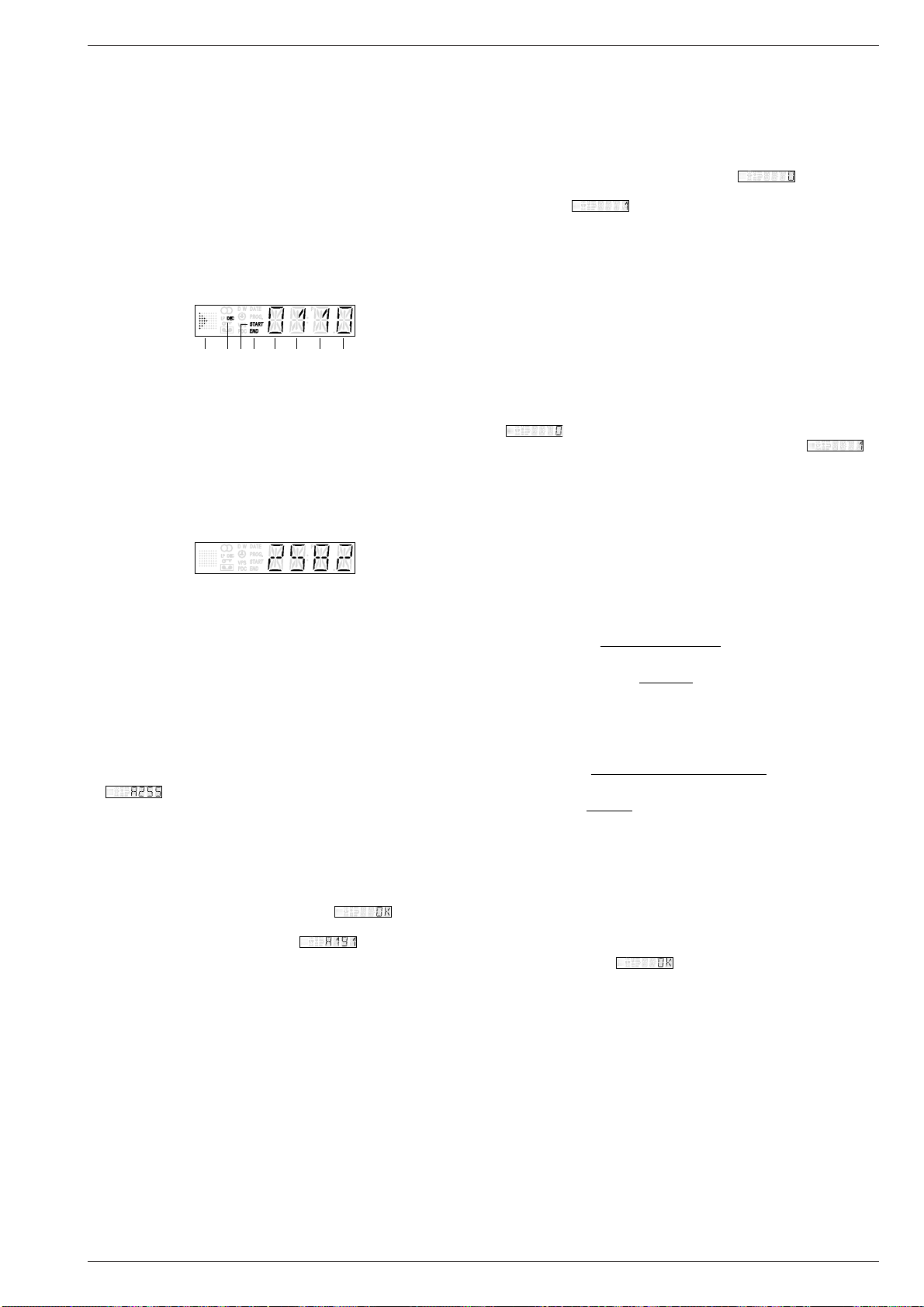
Level 40: VCR Option Codes
The VCR option codes "A"…"E" serve the purpose of activating the
respective software of the different VCR versions stored in the maskprogrammed µC's. The option code is stored in the EEPROM.
– When calling up Level 40 the request for entering option code "A"
( ) appears on the display.
– Select the desired option code "A"…"E" with the "–" or "+" button.
– Entering the option code, for example option code "A":
– Enter option code "A", see VCR type plate (e.g. "191"), on the
remote control.
Attention: All functions will be available only if the option code
has been entered correctly.
– Confirm the entered code with the "OK" button.
The display shows for approximately 3s . Afterwards,
the recorder switches back automatically requesting another
entry and shows the stored value .
– The option codes "B"…"E" are entered in the same way as option
code "A".
– Checking the option codes:
– The option codes "A"…"E" can be checked by pressing the "–" or
"+" button without having entered an option code previously.
Level 51: Headwheel Position Indicator Adjustment
This adjustment is necessary on replacement of the headwheel or
EEPROM (IC7890).
Preparation before calling up this level:
– Play the test cassette.
This adjustment is started automatically on calling up the level. During
the adjustment process the display shows . On successful
completion the resulting value is stored in the EEPROM. The display
then shows .
If the adjustment is not carried out successfully the machine ejects the
cassette and terminates the service test programme. Cause: Test
cassette, headwheel or technical defect (e.g. µC)
Level 52: ACC Adjustment (Automatic Contour Control, option)
The ACC needs to be adjusted on replacement of the headwheel or
EEPROM (IC7890)
Preparation before calling up this level:
– Feed in a black raster test pattern without burst to EURO-AV1 socket
– Play back the record / play cassette.
This adjustment is started automatically on calling up this level
(recording for 10s in SP/LP mode each and while playing back this recording
the VCR is adjusted)
. During this process the display shows
.The resulting value is stored in the EEPROM on successful
completion of this adjustment. The display then shows .
If the adjustment is not carried out successfully the machine ejects the
cassette. Cause: Preparation, cassette, headwheel or technical defect (e.g.
µC).
Level 53: Timer Clock Adjustment
Preparation before calling up this level:
– Level 99 - measure the timer clock output and note down the
measured value (f
– Calculation of the correction value:
f
= measured frequency
mess
f
= desired frequency (2048.0000Hz)
soll
Deviation =
Correction value = +128
).
mess
1 x 10⁶ x (f
Deviation
mess
f
soll
0.763
– f
soll
)
Example:
f
= 2047.9700Hz
mess
f
= 2048.0000Hz
soll
-14.648 =
108.80 = +128
1 x 106 x (2047.97Hz – 2048Hz)
2048Hz
-14.648
0.763
Rounded correction value to be entered: 109
If the calculated correction value lies outside the range 0…255 the
quartz Q1297 may be technically defective.
Entering the correction value
– On calling up Level 53 the display shows the currently valid correc-
tion value "0"…"255".
– Enter the correction value (rounded) and confirm the value by
pressing the "OK" button. As a check, the display shows for
approximately 3s .
GRUNDIG Service 2 - 5
k

Service Test Programme & Special Functions GV 27 …, GV 47 …, GV 7…
Level 60: Audio Level Adjustment of IC7780 (FV, option)
The audio level is to be adjusted on replacement of the stereo decoder
(IC7780) or the EEPROM (IC7890).
Preparation before calling up this level:
– Connect the AF millivoltmeter to the EURO-AV1 socket, contact 1
– Feed in a white test pattern with sound carrier ("stereo" sound
modulation, right channel 1kHz sine, ±27kHz deviation) to the aerial
input socket
– EE operating mode
On calling up adjustment level 60, the actual setting "0"…"9" is
displayed. Set the output level with the button "–" or "+" to 500mV
±50mV. Each time one of these buttons is pressed the level changes
by 0.5dB and the set value is stored in the EEPROM.
Level 61: Audio Channel Separation of IC7780 (FV, option)
The audio channel separation is to be adjusted on replacement of the
stereo decoder (IC7780) or the EEPROM (IC7890).
Preparation before calling up this level:
– Connect the AF millivoltmeter to the EURO-AV1 socket, contact 3
(left channel)
– Feed in a white test pattern with sound carrier ("stereo" sound
modulation, right channel 1kHz sine, ±27kHz deviation) to the aerial
input socket.
– EE operating mode
On calling up adjustment level 61, the actual setting "0"…"49" is
displayed. Set the noise voltage of the left channel with the button "–
" or "+" to minimum. Each time one of these buttons is pressed the level
changes by 0.1dB and the set value is stored in the EEPROM.
Level 62: Standard Sound Playback Level of IC7850 (AF, option)
The standard sound playback level needs to be adjusted on replacement of IC7850 or of the EEPROM (IC7890).
Preparation before calling up this level:
– Connect the AF millivoltmeter to the EURO-AV1 socket, contact 1
– Feed in a sound signal (1kHz sine, 0.7V
contacts 2 and 6.
– Record the sound signal.
On calling up Level 62, the actual setting "0"…"15" is displayed. Play
back the recorded sound signal (standard sound playback) and set the
output level with the "–" or "+" button to 500mV
one of these buttons is pressed the level changes by 1dB and the set
value is stored in the EEPROM.
Level 99: Timer Clock Output
For adjusting the timer clock (Level 53), the timer oscillator frequency
(approx. 2048Hz) must be measured at this level on IC7201-(80)
"HEST" of the keyboard control unit (DC) (resolution: 6 digits at least).
Note it down (f
Note:
After selection of this level, the display is dark and no function of the
VCR is active. This level and the service test programme can be
terminated only by disconnecting the VCR from the mains.
mess
).
) to EURO-AV1 socket
rms
±50mV. Each time
rms
2. Special Functions
Continuous Operation Test
The continuous recording and playback test is part of the service test
programme and helps to find occasionally appearing faults. The
discovered fault is stored in the EEPROM and is saved even if the VCR
is disconnected from the mains.
Calling up the Continuous Operation Test
– Start the continuous test with button ●(Record) or e(Play).
rms
Terminating the Continuous Operation Test
– Press ■(STOP) button or 8 "STANDBY" button.
Cleaning the Headwheel
The video heads are cleaned briefly during the period the video tape
is threaded in. By pressing the e button (min. 5s) the cleaning in play
mode can be activated for approximately 10s. In doing so, the tape
transport is stopped and the video head cleaning roller is pressed
against the headwheel. Afterwards, play is continued.
Erasing the RAM and EEPROM
Depress the 8 "STANDBY" on the machine while connecting it to the
mains and hold the button for at least 5s.
The EEPROM and the internal processor RAM are erased and
initialized. In doing so, the user programmable station memory and the
timer data are erased. The specific data of the VCR, the tape deck
parameters, VCR option codes, and the adjustment values remain
unchanged.
Replacement of the EEPROM IC7890
Attention: On replacement of the EEPROM, IC7890, the VCR option
codes, Level 40, must be entered and the software must
be readjusted according to the Levels 51, 52, 53, 60, 61
and 62.
Data-Programmer "IDP2"
Note: The transfer of the channel settings stored in the Data-Pro-
grammer is only possible in VCR1 Mode.
– Press "EJECT" button (to eject the loaded cassette).
– Press the ■(STOP) button on the remote control and
the "INSTALL" button on the video recorder in that order and hold
them down for at least 5 seconds. The display will then show
"MENU".
– Transfer the channel settings with the Data-Programmer "IDP2"
(see Operation Manual "IDP2").
– On completion of the data transfer press 8 "STANDBY".
2 - 6 GRUNDIG Service
k

GV 27 …, GV 47 …, GV 7… Abgleichvorschriften
D
Abgleichvorschriften
1. Chassisplatte (QMB)
SCL
9005
11
1
C
B
A
11
1
2
3
5
6
TUNER
20
&
MODUL.
STV6400
(TUMOD)
1701
11
40,4MHz
17
HF-AFC
1720
1
1
28 15
40,4MHz
FRONT-
END
(FV)
9038
NICAM (QNIC)
110
20 11
21
20
21
20
SDA
9007
10
1
7507
5721
7720/7721
TDA98xx
16 9
5VASW
STEREO
TDA9840
7780
EURO-AV1 / Scart 1
EURO-AV2 / Scart 2
IN/OUT (IO)
1
1711
Band I / PLL
3748
14
AFC
5725
1
8
HEF4053
7722
HEF4053
7513
1
16 9
1710
1
AGC
3742
AFC
9095
1
2
1
2
Audout
HEAD-AMP.
8
AUDIO-FM
(AF)
12
TAE
7461
CLOCHE
ANTI-CLOCHE
5103
5100
7110
32 17
TDA4722
116
SECAM L
(VS-S)
VPS/PDC (VP)
1418
CLOCHE
7
1
1962
(HA)
PAL-Curr.
TDA9604
7850
1
ANTI-
1915, 1916
PAL
Curr.
24
SEC-Curr.
5208
33
3159
7890
24C08
1
3007
14
65
BIAS R BIAS
5603
BIAS-2
BIAS-1
65
VIDEO SIGNAL
PROCESSING
(VS)
17
14 8
FOLLOW TV
(FM)
SEC-Curr.
WTL
7465
24
LC74781
7800
DISPLAY
TMP87CS71F
CONTROL
(DC)
1
3618
999
QQP
LC89980M
7003
13
12
7201/7210
HEAD
GNDAL
9034
9154
3606
1
85
4
1
1
LA71520F
7007
25
41
16 7
14 8
25
41
5001
LM339
7860
3031
5VASW
LED
6460
1
1930
PB-
LEVEL
18 10
3160
19
Lum. Ampl.
check
7460
9
SAA1310
FTA
7466
WTR
7464
20
TMP91C642
7400/7401
33
52
1944
1
TDA5241
7300
1
1810
85
1
1
DECK ELECTRONIC
(DE)
INIT
1480
4
1353
T1,25A
7354
MC44603P
8189
7462
1
1
SOC1012T
+5V
TAS
3379
1
46
17
Transformer
5353
10111 12 13 14 15 16 17 18
POWER
SUPPLY
9071
TRIV
(PS)
SWIN (HP1)
T100mA
9070
1945
1350
1351
T500mA
1352
T500mA
1356
T1A
1355
T1A
65
1.1 Chassisplatte – Netzteil (PS)
Meßgerät: Digitalvoltmeter
Abgleich Vorbereitung Abgleichvorgang
1. +5V, R3379 Spannung mit R3379 auf 5,3V
±0,03V einstellen.Digitalvoltmeter:....................... Drahtbrücke 9038 (5VASW)
1.2 Chassisplatte – Bedieneinheit (DC)
Meßgerät: Frequenzzähler
Abgleich Vorbereitung Abgleichvorgang
1. Uhr-Takt Hinweise zu der Ebene 53 beachten (siehe Seite 2-2).
Servicetestprogramm aufrufen (siehe Seite 2-1).
Ebene 53 aufrufen (siehe Seite 2-1).
Servicetestprogramm beenden (siehe Seite 2-1).
1.3 Chassisplatte – Laufwerksteuerung / Deck-Elektronik (DE)
Meßmittel: Testcassette, Videocassette von Markenhersteller
Servicearbeiten nach Austausch …
… der Kopfscheibe: Abgleich Nr. 1, 3
… des IC7890: Abgleich Nr. 1, 2, 3; Bedieneinheit: Abgleich Nr. 1; Empfangseinheit: Abgleich Nr. 4, 5; Standardton: Abgleich Nr. 2 (bei Stereo-Geräten)
Abgleich Vorbereitung Abgleichvorgang
1. KopfradLagengeber
2. Geräte-Optionscode
3. Automatic Contour
Control (Option)
Servicetestprogramm aufrufen (siehe Seite 2-1).
Ebene 51 aufrufen (siehe Seite 2-1).
Servicetestprogramm aufrufen (siehe Seite 2-1).
Ebene 40 aufrufen (siehe Seite 2-1).
Servicetestprogramm aufrufen (siehe Seite 2-1).
Ebene 52 aufrufen (siehe Seite 2-1).
GRUNDIG Service 3 - 1
Hinweise zu der Ebene 51 beachten (siehe Seite 2-2).
Servicetestprogramm beenden (siehe Seite 2-1).
Geräte-Optionscode eingeben (siehe Ebene 40, Seite 2-2).
Servicetestprogramm beenden (siehe Seite 2-1).
Hinweise zu der Ebene 52 beachten (siehe Seite 2-2).
Servicetestprogramm beenden (siehe Seite 2-1).
j

Abgleichvorschriften GV 27 …, GV 47 …, GV 7…
1.4 Chassisplatte – Empfangseinheit (FV)
Meßgeräte: Oszilloskop mit Tastkopf 10:1, Voltmeter, Millivoltmeter, Farbgenerator
Servicearbeiten nach Austausch des …
… Tuners, IC7720, IC7721: Abgleich Nr. 2
… IC7720 (TDA9800T): R3748
… IC7780: Abgleich Nr. 4, 5
Abgleich Vorbereitung Abgleichvorgang
1. Demodulatorkreis
PAL, F5725
(AFC)
SECAM-L,
R3748
(Band I)
2. Tuner-Regelspannungseinsatz,
R3742 (AGC)
3. Trägerrest-Band I,
F5721
(40,4MHz)
4. Stereo-Pegel
5. Übersprechen
(PLL) entfernen. Der neue TDA9800T stellt automatisch einen "Default"-Wert ein.
Voltmeter: ............................. IC7720-(15) oder IC7721-(20)
EE-Betrieb
Farbgenerator 38,9MHz - 500mV
Farbgenerator 33,9MHz, 500mV
Taste "
SYSTEM
" so oft drücken bis im Display "SEC" erscheint.
: .......... Tuner 1701-(17)
SS
: ........... Tuner 1701-(17)
SS
PAL-Weißtestbild mit Tonträger (keine Tonmodulation, Kanal 27,
Antennenpegel 74dBµV) in betriebswarmes Gerät einspeisen.
Spannung mit F5725
Spannung mit R3748
Amplitude mit R3742 (AGC) auf 550mVSS +0/-50mV einstel-
len.
Oszilloskop: ................................................ Tuner 1701-(17)
EE-Betrieb
Farbgenerator 40,4MHz - 300mVSS: .......... Tuner 1701-(17)
Oszilloskop: .......................................................... F1720-(1)
Amplitude mit F5721 (40,4MHz) auf Minimum (mindestens 5dB
kleiner als das Eingangssignal) einstellen.
EE-Betrieb
Servicetestprogramm aufrufen (siehe Seite 2-1).
Ebene 60 aufrufen (siehe Seite 2-1).
Servicetestprogramm aufrufen (siehe Seite 2-1).
Ebene 61 aufrufen (siehe Seite 2-1).
Hinweise zu der Ebene 60 beachten (siehe Seite 2-3).
Servicetestprogramm beenden (siehe Seite 2-1).
Hinweise zu der Ebene 61 beachten (siehe Seite 2-3).
Servicetestprogramm beenden (siehe Seite 2-1).
(AFC) auf 2,5V ±0,2V einstellen.
(Band I) auf 2,5V ±0,2V einstellen.
1.5 Chassisplatte – Video/Chroma (VS, VS-S)
Meßgeräte: Oszilloskop mit Tastkopf 10:1, Farbgenerator
Servicearbeiten nach Austausch des IC7007 oder des IC7110: Abgleich Nr. 1
Abgleich Vorbereitung Abgleichvorgang
1. Chroma-Aufsprechpegel
Laufwerk ausbauen (siehe Seite 1-9)
Servicetestprogramm – Ebene 10 aufrufen (siehe Seite 2-1).
PAL-Rotflächentestbild mit 75% Sättigung (Verhältnis Burst : Chroma
= 1 : 2,2) an der AV1-Buchse einspeisen und aufnehmen.
Die Amplitude des FM-Signals muß 420mV
einer Abweichung von mehr als ±40mVSS liegt ein technischer
Defekt (z.B. IC7007) vor.
Oszilloskop: ................................... R3031 (T7006 – Emitter)
R3031 (T7006 – Emitter) mit L5001 (5VASW) verbinden.
PAL,
R3007
(PAL Curr.)
SECAM-L,
R3159 (SECAM Curr. )
Oszilloskop: ............................................. R3007 – Schleifer
PAL-Rotflächentestbild mit 75% Sättigung
= 1 : 2,2) an der AV1-Buchse einspeisen und aufnehmen.
(Verhältnis Burst : Chroma
Oszilloskop: ............................................ R3159 – Schleifer
SECAM-L-Rotflächentestbild mit 75% Sättigung
Burst : Chroma = 1 : 2,2) an der AV1-Buchse einspeisen und aufneh-
(Verhältnis
men.
Chroma-Signal mit R3007 (PAL Curr.) auf 160mVSS ±20mVSS (2-KopfGeräte) bzw. 130mVSS ±20mVSS (4-Kopf-Geräte) einstellen.
Chroma-Signal mit R3159
(SECAM Curr.) auf 210mV
einstellen.
Servicetestprogramm beenden, Verbindung von R3031 mit
L5001 auftrennen und Laufwerk einbauen.
1.6 Chassisplatte – Standardton (AL)
Meßgeräte / Meßmittel: Frequenzzähler, NF-Millivoltmeter, Tongenerator, Farbgenerator, Videocassette von Markenhersteller
Servicearbeiten nach Austausch des AW-Kopfes, der L5603 oder des IC7007: Abgleich Nr. 1, 2
Abgleich Vorbereitung Abgleichvorgang
1. Löschfrequenz,
F5603
(BIAS R)
1.1 Vormagneti-
sierung, R3618 (BIAS)
1.2 Frequenzgang-
prüfung
2. Wiedergabepegel
bei Mono-Geräten,
R3160 (PB-Lev.)
bei Stereo-Geräten
Frequenzzähler: .......................... Drahtbrücke 9034 (Head)
Aufnahme
NF-Millivoltmeter: ..................... BIAS1 bzw. BIAS2 (R3606)
Aufnahme
–FBAS-Signal über EURO-AV1-Buchse, Kontakt 20 einspeisen.
–Audio-Signal 200mV
EURO-AV1-Buchse, Kontakte 2 oder 6 einspeisen.
(480mVss) vom Tongenerator an der
eff
– Aufnahme mit jeweils ca. 1 Minute 400Hz- und 8kHz-Ton durch-
führen. Anschließend diese Aufnahme (MONO) wiedergeben.
–NF-Millivoltmeter (Oszilloskop) an EURO-AV1-Buchse,
Kontakt 1 oder 3.
NF-Millivoltmeter: .. EURO-AV1-Buchse, Kontakte 1 oder 3
Tongenerator (1kHz / 0,7V
.................................EURO-AV1-Buchse, Kontakte 2 oder 6
):
eff
FBAS-Signal über EURO-AV1-Buchse, Kontakt 20 einspeisen.
Eigenaufnahme (Normalplay) wiedergeben.
Servicetestprogramm aufrufen (siehe Seite 2-1).
Ebene 62 aufrufen (siehe Seite 2-1).
Frequenz mit F5603
(BIAS R) auf 70kHz ±10kHz einstellen.
Spannungsabfall an R3600 mit R3618 (BIAS) auf 15mV
Frequenzgang prüfen.
Das Spannungsverhältnis von 400Hz zu 8kHz darf nicht
größer als 1:0,7 bzw. 0,7:1 sein (±3dB). Überschreitet das
Spannungsverhältnis diese Grenzen, ist die Vormagnetisierung zu verändern:
Wiedergabespannung bei 8kHz …
… vergrößern: "BIAS" verringern.
… verkleinern: "BIAS" erhöhen.
Ausgangsspannung mit R3160 (PB-Lev.) auf 0,5V
einstellen.
Hinweise zu der Ebene 62 beachten (siehe Seite 2-3).
Servicetestprogramm beenden (siehe Seite 2-1).
betragen. Bei
SS
±30mV
SS
einstellen.
eff
±50mV
eff
SS
3 - 2 GRUNDIG Service
j
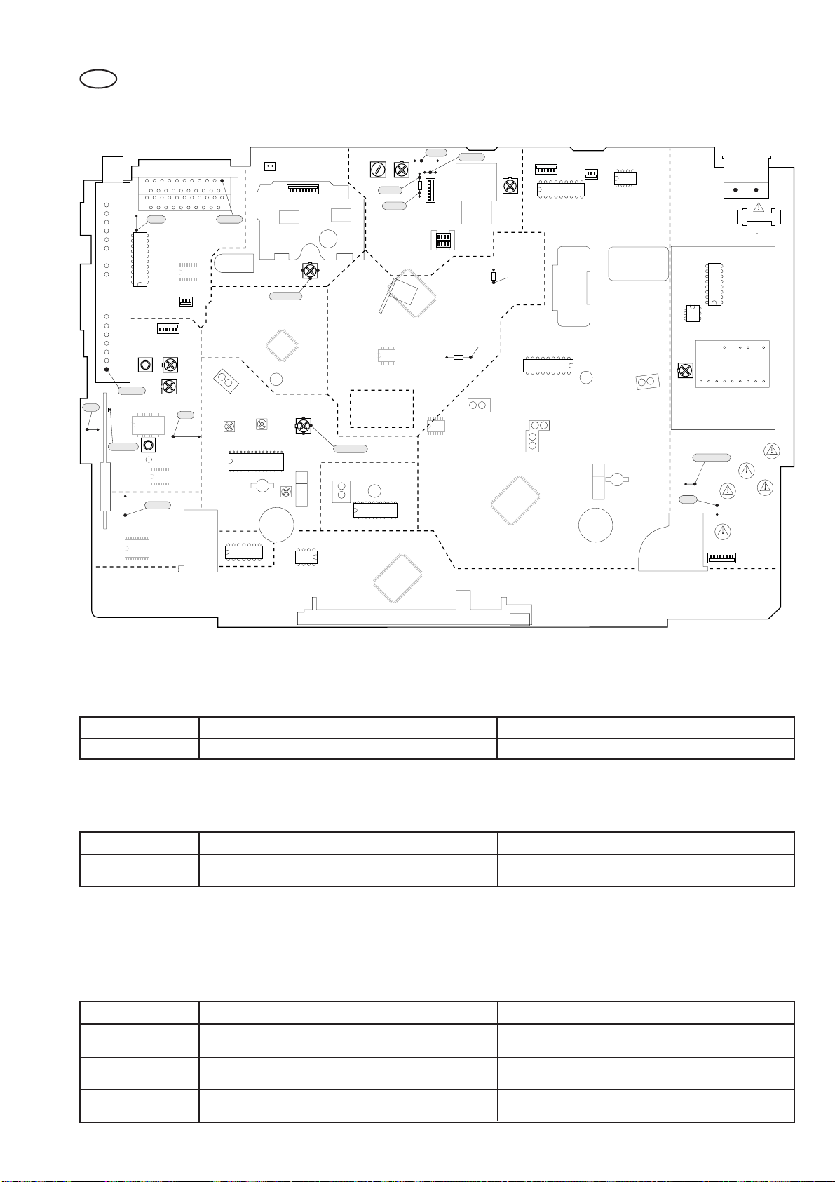
GV 27 …, GV 47 …, GV 7… Adjustment Procedures
GB
Adjustment Procedures
1. Chassis Board (QMB)
SCL
9005
11
1
C
B
A
11
1
2
3
5
6
TUNER
20
&
MODUL.
STV6400
(TUMOD)
1701
11
40,4MHz
17
HF-AFC
1720
1
1
28 15
40,4MHz
FRONT-
END
(FV)
9038
NICAM (QNIC)
110
20 11
21
20
21
20
SDA
9007
10
1
7507
5721
7720/7721
TDA98xx
16 9
5VASW
STEREO
TDA9840
7780
EURO-AV1 / Scart 1
EURO-AV2 / Scart 2
IN/OUT (IO)
1
1711
Band I / PLL
3748
14
AFC
5725
1
8
HEF4053
7722
HEF4053
7513
1
16 9
1710
1
AGC
3742
AFC
9095
1
2
1
2
Audout
HEAD-AMP.
8
AUDIO-FM
(AF)
12
TAE
7461
CLOCHE
ANTI-CLOCHE
5103
5100
7110
32 17
TDA4722
116
SECAM L
(VS-S)
VPS/PDC (VP)
1418
CLOCHE
7
1
1962
(HA)
PAL-Curr.
TDA9604
7850
1
ANTI-
1915, 1916
PAL
Curr.
24
SEC-Curr.
5208
33
3159
7890
24C08
1
3007
14
65
BIAS R BIAS
5603
BIAS-2
BIAS-1
65
VIDEO SIGNAL
PROCESSING
(VS)
17
14 8
FOLLOW TV
(FM)
SEC-Curr.
WTL
7465
24
LC74781
7800
DISPLAY
TMP87CS71F
CONTROL
(DC)
1
3618
999
QQP
LC89980M
7003
13
12
7201/7210
HEAD
GNDAL
9034
9154
3606
1
85
4
1
1
LA71520F
7007
25
41
16 7
14 8
25
41
5001
LM339
7860
3031
5VASW
LED
6460
1
1930
PB-
LEVEL
18 10
3160
19
Lum. Ampl.
check
7460
9
SAA1310
FTA
7466
WTR
7464
20
TMP91C642
7400/7401
33
52
1944
1
TDA5241
7300
1
1810
85
1
1
DECK ELECTRONIC
(DE)
INIT
1480
4
1353
T1,25A
7354
MC44603P
8189
TAS
7462
1
1
SOC1012T
+5V
3379
1
46
17
Transformer
5353
10111 12 13 14 15 16 17 18
POWER
SUPPLY
9071
TRIV
(PS)
SWIN (HP1)
T100mA
9070
1945
1350
1351
T500mA
1352
T500mA
1356
T1A
1355
T1A
65
1.1 Chassis Board – Power Supply (PS)
Test equipment: Digital Voltmeter
Adjustment Preparation Adjustment Procedure
1. +5V, R3379 Adjust voltage to 5.3V ±0.03V with R3379.Digital voltmeter:........................ wire bridge 9038 (5VASW)
1.2 Chassis Board – Keyboard Control Unit (DC)
Test equipment: Frequency Counter
Adjustment Preparation Adjustment Procedure
1. Clock Observe the instructions for Level 53 (see page 2-5).
Call up the Service Test Programme (see page 2-4).
Call up Level 53 (see page 2-4).
Terminate the Service Test Programme (see page 2-4).
1.3 Chassis Board – Deck Control / Deck Electronic (DE)
Test aids: Test Cassette, branded Video Cassette
Service work after changing the …
… Headwheel: Adjustment no. 1, 3
… IC7890: Adjustment no. 1, 2, 3; Keyboard Control Unit: Adjustment no. 1, Frontend: Adjustment no. 4, 5; Standard Sound: Adjustment no. 2
(only for stereo VCR)
Adjustment Preparation Adjustment Procedure
1. Headwheel Position
Indicator
2. VCR Option Code
Call up the Service Test Programme (see page 2-4).
Call up Level 51 (see page 2-4).
Call up the Service Test Programme (see page 2-4).
Call up Level 40 (see page 2-4).
3. Automatic Contour
Control (Option)
Call up the Service Test Programme (see page 2-4).
Call up Level 52 (see page 2-4).
GRUNDIG Service 3 - 3
Observe the instructions for Level 51 (see page 2-5).
Terminate the Service Test Programme (see page 2-4).
Enter VCR option code (see Level 40, see page 2-5).
Terminate the Service Test Programme (see page 2-4).
Observe the instructions for Level 52 (see page 2-5).
Terminate the Service Test Programme (see page 2-4).
k

Adjustment Procedures GV 27 …, GV 47 …, GV 7…
1.4 Chassis Board – Frontend (FV)
Test equipment: Oscilloscope with 10:1 Test Probe, Voltmeter, AF Millivoltmeter, Colour Generator
Service work after replacing the
… Tuner, IC7720, IC7721: Adjustments no. 2
… IC7720 (TDA9800T): Remove R3748
… IC7780: Adjustments no. 4, 5
Adjustment Preparation Adjustment Procedure
1. Demodulator Circuit
Voltmeter: ................................. IC7720-(15) or IC7721-(20)
EE-mode.
PAL, F5725
SECAM-L,
R3748 (Band I)
2. Delayed AGC
Voltage,
R3742 (AGC)
(AFC)
Colour generator 38.9MHz - 500mV
Colour generator 33.9MHz / 500mV
Press button "SYSTEM" repeatedly until "SEC" is displayed.
Feed in a PAL white test pattern with sound carrier (without sound
modulation, Ch27, 74dBµV aerial signal) into the warmed-up VCR.
Oscilloscope: .............................................. Tuner 1701-(17)
EE-mode.
3. Residual Carrier
Band I,
F5721 (40.4MHz)
4. Stereo Level
Colour generator 40.4MHz - 300mVPP: ...... Tuner 1701-(17)
Oscilloscope: ........................................................ F1720-(1)
EE-mode.
Call up the Service Test Programme (see page 2-4).
Call up Level 60 (see page 2-4).
5. Cross Talk
Call up the Service Test Programme (see page 2-4).
Call up Level 61 (see page 2-4).
(PLL). The new TDA9800T automatically sets a "Default" value.
: ...... Tuner 1701-(17)
PP
: ...... Tuner 1701-(17)
PP
Set the voltage with F5725
Set the voltage with R3748
Set the amplitude with R3742 (AGC) to 550mVPP +0/-50mV.
Set the amplitude with F5721 (40.4MHz) to minimum (5dB
lower at least than the input signal).
Observe the instructions for Level 60 (see page 2-6).
Terminate the Service Test Programme (see page 2-4).
Observe the instructions for Level 61 (see page 2-6).
Terminate the Service Test Programme (see page 2-4).
(AFC) to 2.5V ±0.2V.
(Band I) to 2.5V ±0.2V.
1.5 Chassis Board – Video/Chroma (VS, VS-S)
Test equipment: Oscilloscope with 10:1 Test Probe, Colour Generator
Service work after replacing the IC7007 or 7110: Adjustment no. 1
Adjustment Preparation Adjustment Procedure
1. Chroma Recording
Current
Remove the drive mechanism (see page 1-9)
Call up the Service Test Programme – Level 10 (see page 2-4)
Feed in a PAL red raster test pattern with 75% saturation (ratio
The FMF signal must have an amplitude of 420mVpp. If the
value deviates by more than ±40mV
defect (e.g. IC7007).
burst: chroma = 1 : 2.2) into the AV1 socket and record it.
Oscilloscope: ................................ R3031 (T7006 – Emitter)
Connect R3031 (T7006 – Emitter) to L5001 (5VASW).
PAL,
R3007
(PAL-Curr.)
Oscilloscope: ................................................ R3007 – wiper
Feed in a PAL red raster test pattern with 75% saturation (ratio
Set Chroma signal with R3007 (PAL-Curr.) to 160mVPP ±20mV
(for 2-Head-VCR) or 130mVPP ±20mVPP (for 4-Head-VCR).
burst: chroma = 1 : 2.2) into the AV1 socket and record it.
SECAM-L,
R3159 (SECAM-Curr .)
Oscilloscope: ................................................ R3159 – wiper
Feed in a SECAM-L red raster test pattern with 75% saturation
(ratio burst: chroma = 1 : 2.2) into the AV1 socket and record
it.
Set Chroma signal with R3159
±30mV
.
PP
Terminate the Service Test Programme, disconnect R3031
from L5001 and reassemble the drive mechanism.
1.6 Chassis Board – Standard Sound (AL)
Test equipment / aids: Frequency Counter, AF Millivoltmeter, AF Generator, Colour Generator, branded Video Cassette.
Service work after replacing the RP-Head, L5603 or IC7007: Adjustment no. 1, 2
Adjustment Preparation Adjustment Procedure
1. Erase Frequency,
F5603
(BIAS R)
1.1 Bias, R3618 (BIAS)
1.2 Frequency
Response Test
2. Playback Level for
Mono VCR,
R3160 (PB-Lev.)
for Stereo VCR
Frequency counter: ....................... wire bridge 9034 (Head)
Record
AF millivoltmeter:.......................... BIAS1 or BIAS2 (R3606)
Record.
–Feed in a CCVS signal via EURO-AV1 socket, contact 20.
–Feed an audio signal of 200mV
generator to the EURO-AV1 socket, contact 2 or 6.
(480mVPP) from the AF
rms
–Make a recording of 400Hz and 8kHz each of 1 min at least.
Afterwards play back these recordings (MONO).
–Connect an AF millivoltmeter (oscilloscope) to EURO-AV1
socket, contact 1 or 3.
AF millivoltmeter:............ EURO-AV1 socket, contact 1 or 3
AF generator (1kHz / 0.7V
........................................EURO-AV1 socket, contact 2 or 6
):
rms
Feed in a CCVS signal via EURO-AV1 socket, contact 20.
Play back the self made recording (Normal Play).
Call up the Service Test Programme (see page 2-4).
Call up Level 62 (see page 2-4).
With F5603 (BIAS R) set the frequency to 70kHz ±10kHz.
Set the voltage drop across R3600 with R3618 (BIAS) to
15mV
.
rms
Check the frequency response.
The voltage ratio of 400Hz to 8kHz must not be higher than
1:0.7 or 0.7:1 (±3dB). If the voltage ratio exceeds these limits,
the bias must be altered:
To increase the playback voltage at 8kHz: Reduce "BIAS".
To reduce the playback voltage at 8kHz: Increase "BIAS".
Set output voltage with R3160 (PB-Lev.) to 0.5V
Observe the instructions for Level 62 (see page 2-6).
Terminate the Service Test Programme (see page 2-4).
there is a technical
pp
(SECAM-Curr.) to 210mV
±50mV.
rms
PP
PP
3 - 4 GRUNDIG Service
k

GV 27 …, GV 47 …, GV 7… Platinenabbildungen und Schaltpläne / Layout of PCBs and Circuit Diagrams
Platinenabbildungen und Schaltpläne / Layout of PCBs and Circuit Diagrams
Abkürzungen / Abbreviations
Signal Abkürzungen Abbreviations Verwendung / Application
+5AS +5V Analog nach Sicherung 1700 +5V analog after fuse 1700 QNIC
+5ASS +5V Analog nach Drossel 5706 +5V analog after coil 5706 QNIC
+5D +5V Digital +5V digital DE QNIC
-28V -28V für Display -28V for display DC IO PS
-7V -7V für "IN/OUT" -7V for "IN/OUT" IO
12SW +12V Analog, (< 6W geschaltet) +12V analog, (<6W switched) AL FV PS QNIC
12VA +12 Analog +12V analog AF FV IO PS
14VM1 +14V für Fädel- und Kopfradmotor +14V for threading and head motor DE PS
2FSC Doppelte Farbhilfsträgerfrequenz Double colour subcarrier frequency OS VS
33V +33V für Tunerabstimmung +33V tuner adjustment FV PS
5VA +5V Analog +5V analog AF FV IO OS PS
5VASW +5V Analog (< 6W geschaltet) +5V analog (< 6W switched) DE FV HA OS PS QNIC VS VS-S
5VASW2 +5V Analog nach Drossell 5802 +5V analog after coil 5802 OS
5VASWB +5V Analog nach Drossell 5726 +5V analog after coil 5726 FV
5VD +5V Digital +5V digital DC DE FV PS
5VD1 +5V Digital nach Drossel 5200 +5V digital after coil 5200 DC
5VD2 +5V Digital nach Drossel 5400 +5V digital after coil 5400 DE
8SC1 Scart 1 Pin 8, Ausgang Scart 1 pin 8, output DE IO
8SC2 Scart 2 Pin 8, Eingang Scart 2 pin 8, input DE IO
9/14VM2 Capstanmotor Versorgung, geschaltet Capstan motor supply, switched DE PS
AEH 1/2 Audio Löschkopf Audio erase head AL
AF FM-Ton FM sound
AF1 Audio links vom Stereodecoder Audio left from stereo decoder AF AL FV IO
AF2 Audio rechts vom Stereodecoder Audio right from stereo decoder AF FV
AFC Automatische Frequenzkontrolle Automatic frequency control DC FV
AFE Audio von der Empfangseinheit Audio from Frontend FV IO QNIC
AGC Automatische Verstärkungsregelung Automatic gain control DE FV
AH1/2/C Audioköpfe Audio heads HA
AIN1 Audio Eingang von Scart 1 Audio input scart 1 AL IO
AIN1L Audio Eingang von Scart 1, links Audio input scart 1, left AF IO
AIN1R Audio Eingang von Scart 1, rechts Audio input scart 1, right AF IO
AIN2 Audio Eingang von Scart 2 Audio input scart 2 AL IO
AIN2L Audio Eingang von Scart 2, links Audio input scart 2, left AF IO
AIN2R Audio Eingang von Scart 2, rechts Audio input scart 2, right AF IO
AINFL Audio links von der Frontbuchse Audio left from front socket AF IO
AINFR Audio rechts von der Frontbuchse Audio right from front socket AF IO
AL Standardton Standard Sound
AMCO Audio zum Modulator Audio to the modulator AF FV
AMLP Audio "Mono" Wiedergabe Audio "mono" playback AF AL FV IO
AMLR Audio "Mono" Aufnahme Audio "mono" record AF AL IO
AN1/2 Analogspannung der Tastenmatrix Analog voltage of keyboard matrix DC
ANIL Audio "NICAM", links Audio "NICAM", left FV QNIC
ANIR Audio "NICAM", rechts Audio "NICAM", right FV QNIC
AOUT1L Audio Ausgang von Scart 1, links Audio output from scart 1, left AF IO
AOUT1R Audio Ausgang von Scart 2, rechts Audio output from scart 2, right AF IO
AOUT2L Audio Ausgang von Scart 2, links Audio output from scart 2, left AF IO
AOUT2R Audio Ausgang von Scart 2, rechts Audio output from scart 2, right AF IO
APH Audio Wiedergabekopf Audio playback head AL
ARH Audio Aufnahmekopf Audio record head AL
BLANKING Austastimpuls (für RGB-Durchschleifsignal) Blanking pulse (for RGB loop-through signal) IO
BLUE Blau Signal zwischen Scart 1/2 Blue signal between scart 1/2 IO
CAP Capstan Steuerspannung Capstan control voltage DE
CKDET Farbsystem Information Colour system information DE VS
CLKD1 Serieller Bus (Clock) Serial bus (clock) DC DE
CREV Capstan "Reverse" Capstan "reverse" DE
CROT Farbphasenrotation "Ein/Aus" Colour phase rotation "on/off" DE VS
CSCP Farbphasenumschaltung im LP-Betrieb Colour phase change in LP mode DE VS
CSI Farbsystem Information Colour system information DE VS-S
CSP Chroma-Wiedergabesignal "SECAM" Chrominance playback "SECAM" VS VS-S
CSR Chroma-Aufnahmesignal "SECAM" Chrominance record "SECAM" HA VS-S
CSW 8V/14V Unschaltung für Capstan Motor 8V/14V switching for capstan motor DE PS
CSYNC/1/2 Synchron-Signalgemisch Composite sync pulse DE HA OS VS VS-S
CTL1/2 Signal von der Kontrollspur (CTL) Control track signal (CTL) AL DE
DATD1/2 Daten vom seriellen Bus Serial bus data DC DE
DC Bedieneinheit Keyboard Control Unit
DE Laufwerksteuerung / Deck Elektronik Deck Control / Deck Electronic
DEC Audio-Umschaltung Audio switching voltage IO
ENVC Hüllkur ven Vergleichsignal Envelope comparator signal DE HA
FFP Künstlicher Bildimpuls Artificial frame pulse DE VS
FG/FGD Capstan Tachoimpulse Capstan tacho pulse DE
FM Follow TV Follow TV
FMAP FM Audio Wiedergabe FM audio playback AF HA
FMAR FM Audio Aufnahme FM audio record AF HA
FMPV FM Video-Wiedergabe FM video playback HA VS VS-S
FMRV FM Video-Aufnahme FM video record HA VS
FOME Follow TV-Signal (Videosignale identisch) Follow TV signal (video signals identical) DE FM
GRUNDIG Service 4 - 1

Platinenabbildungen und Schaltpläne / Layout of PCBs and Circuit Diagrams GV 27 …, GV 47 …, GV 7…
Signal Abkürzungen Abbreviations Verwendung / Application
FTA/FTAD Fädeltacho Threading tacho DE
FV Empfangseinheit Frontend
GNDA Masse Analog Ground analog FV IO QNIC
GNDA1/A2 Masse Analog "NICAM" Ground analog "NICAM" QNIC
GNDAF Masse Analog "FM-Ton" Ground analog "FM Sound" AF
GNDAIO Masse Analog "IN/OUT" Ground analog "IN/OUT" IO
GNDAL Masse Analog "Standardton" Ground analog "Standard Sound" AL
GNDD Masse Digital Ground digital AF DE IO QNIC
GNDEO Masse Löschoszillator Ground erase oscillator AL
GNDM Masse für Motoren Ground capstan motor DE
GNDVS Masse Signalelektronik Ground Signal Electronics AF
GNDVSIO Masse Analog "Video, IN/OUT" Ground analog "Video, IN/OUT" IO
GREEN Grün Signal zwischen Scart1/2 Green signal between scart1/2 IO
HA Kopfverstärker Head amplifier
HEHI Display-Heizung (HIGH) Display heater (HIGH) DC PS
HELO Display-Heizung (LOW) Display heater (LOW) DC PS
HEST Heizungsspannung - Steuersignal Heater voltage control signal DC
HP2 Kopfumschaltimpuls Audio Head pulse audio AF DE HA
I/R INIT-Schalter / Aufnahmesperre INIT switch / record prodection DE
ILED Steuerspannung für Bandanfang/ende-Sendediode Switching voltage for start/end of tape transmitting diode DE
INIT Initialisierungsschalter für das Laufwerk Initialisation switch for Deck Mechanism DE
IO IN/OUT IN/OUT
IPOR Reset bei Inbetriebnahme (Invertiert) Power-on reset (inverse) DC DE
IRAF Schaltspannung bei FM-Audio-Aufnahme "LOW" Switching voltage for FM audio record "LOW" DE HA
IREV Dubbing Oszillator Ein/Aus Dubbing oscillator on/off AL DE VS
ISTBY Schaltspannung bei STANDBY "LOW" Switching voltage for Standby "LOW" DC PS
ISWS Video-FM Mute Video-FM mute DE VS
IWIND Kontrollimpulse Verstärkung Control pulse amplification DE
LH1/2/C Longplay Köpfe Longplay heads HA
MEH1/2 Hauptlöschkopf Main erase head AL
MON Monitor Durchschleifsignal Scart 1/2 Monitor loop-through scart 1/2 IO
MOT0-3 Kopfmotor Steuerleitungen Head motor control lines DE
MTA Audio-Stummschaltung Audio mute AL DE
NC Nicht verwendet Not connected DE
OCLK OSD-Bus (Clock) OSD bus (clock) DC OS
OCS OSD-Chip Select OSD chip select DC OS
ODAT OSD-Bus (Daten) OSD bus (data) DC OS
OFP Bildimpuls Frame pulse DE OS
OS OSD OSD
PBV Wiedergabe-Schaltspannung Playback switching voltage DE VS-S
PG/FG Kopfscheibenposition/Geschwindigkeit Headwheel position/speed DE
POS Kopfscheibenposition Headwheel position DE
PS Netzteil Power Supply
PSS PAL oder SECAM-L PAL or SECAM-L DC FV
QMB Chassisplatte Family Board
QNIC NICAM-Decoder NICAM Decoder
RECP Aufnahmesperre Record protection DE
RED Rot-Signal zwischen Scart 1/2 Red signal between scart 1/2 IO
REEL Kopfscheibenmotor-Steuerspannung Headwheel motor control voltage DE
SB1 SECAM Band 1 SECAM band 1 DC FV
SCL I2C Bus - Takt I2C bus clock AF DC FV IO OS QNIC
SCL2 Serieller Bus - Takt Serial bus clock DE VS
SDA I
SDA2 Serieller Bus - Daten Serial bus data DE VS
SFS Schaltspannung für ZF-Tonfilter Switching voltage for IF sound filter DC FV
SH1/2/C Standard play Köpfe Standard play heads HA
SSIF Zweiton Zwischenfrequenz Dual sound intermediate frequency FV QNIC
SWIN Kopfumschaltimpuls Head switching pulse DE HA
SYNC Kontrollimpulse CTL von der Kontrollspur CTL control track pulse DE
TAE Bandende-Erkennung Tape end identification DE
TAS Bandanfang–Erkennung Tape start identification DE
THIO Schaltspannung Einfädeln / Ausfädeln Switching voltage threading in/out DE
TMO Fädelmotor-Schaltspannung Threading motor switching voltage DE
TMO1/2 Fädelmotoranschluß Threading motor connection DE
TRIA/ALI Trackinginformation Audio / Aussteuerungsanzeige Tracking information audio / audio level indication AF DE
TRIV Trackinginformation Video Tracking information video DE HA
VBS Video zur Signalelektronik Video to Signal Electronics FM IO VS
VFR Video von der Frontbuchse Video from front socket IO
VFV Video von der Empfangseinheit Video from Frontend FM FV IO VS
VIN1/2 Videoeingang - Scart 1 / 2 Video input scart 1 / 2 IO
VISS Kontrollspurimpuls Invertierung Control track pulse inversion DE
VMOD Video - Modulator Video - modulator FV IO
VOUT Video von OSD Video from OSD IO OS
VP VPS/PDC VPS/PDC
VREC Video Aufnahme von VS / IO Video record from VS / IO IO VP VS VS-S
VREF Referenzspannung Reference voltage VS-S
VS Video/Chroma (Signalelektronik) Video/Chroma (Signal Electronics)
VS-S SECAM-L (SECAM-VS) SECAM L (SECAM-VS)
VSB Video von der Signalelektronik Video from Signal Electronics OS VS
W/R Synchronspur-Schreiben/Lesen Write/read sync track DE
WTL/WTLD Tachosignal vom linken Wickelteller Wind tacho left DE
WTR/WTRD Tachosignal vom rechten Wickelteller Wind tacho right DE
2
C Bus - Daten I2C bus data AF DC FV IO OS QNIC
4 - 2 GRUNDIG Service
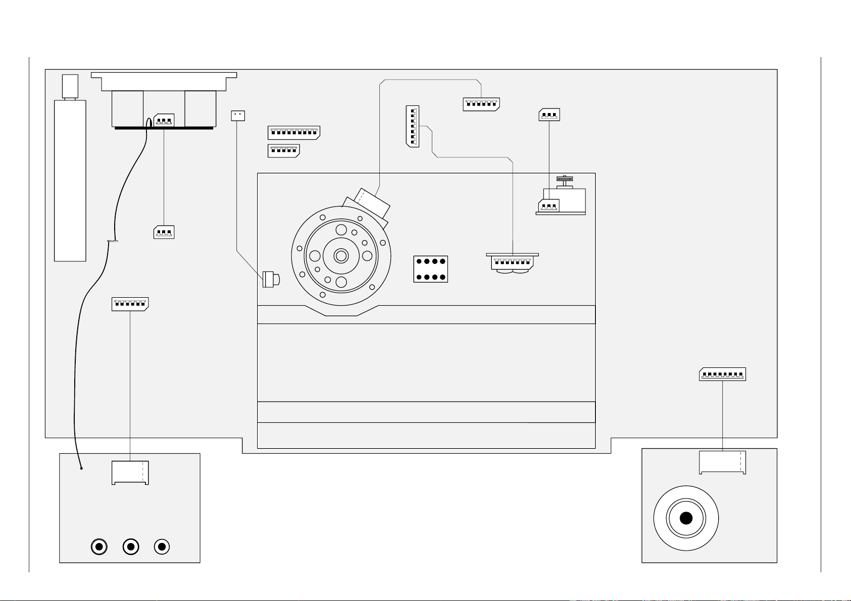
GRUNDIG Service 4 - 3
( # 2645. )
1103
4
3
2
1
5
VID inL inR in
VIDEOAUDIO
1901
6
4
3
2
1
5
SOCKET-Pr.:
6
8004... # 2628.
8001... # 2625.
ARH
1
TD4
Rotating Trafo-Conn.
AH2
AHC
AH1
SH1
SHC
SH2
LH2
LHC
LH1
1915
123456789
1930
M1M3M2
M0
POS
GNDD
12345
6
1-1
6
5
4
3
2
1
GNDD
GNDM2
CREV
FG
+6/16M2
GNDD
+5D
CAP
CAPSTAN-MOTOR-CONN.
1946
567
81
234
TD1(L3)
AUDIO-CONTROL-HEAD
ARH
CTL1
CTL2
AEH1
AEH2
APH
GND
1234567
THREADING MOTOR
ERASE-HEAD
2
1
MEH1
MEH2
TMO1
N.C.
TMO2
M1
M3
M2
M0
POS
GNDD
MOBO-DECK
TD3(L4)
TD2(L8)
1-1
1944
123
1-1
123
1-1
TMO1
N.C.
TMO2
2
3
4
5
6
7
CTL1
CTL2
AEH1
AEH2
APH
GND
8003... # 2627.
1961
12345
1916
2
1
1962
8002... # 2626.
QBOG1
1711
1-1
12VA
GNDVSIO
AINFL
GNDAIO
AINFR
VFR
TUNER + MODULATOR
123
AOUT1R
GNDAIO
AOUT1L
321
7
8
SHUTTLE-Pr.
GND
AN1
5VD
SHUTTLE b2
SHUTTLE b3
SHUTTLE b1
SHUTTLE b4
AN2
1945
1234567
8
GND
AN1
5VD
SHUTTLE b2
SHUTTLE b3
SHUTTLE b1
SHUTTLE b4
AN2
1-1
12VA
GNDVSIO
AINFL
GNDAIO
AINFR
VFR
1-1
1-1
1-1
AOUT1R
GNDAIO
AOUT1L
MEH1
MEH2
1-1
1-1
8006... # 2642.
8007... # 2627. --> 8003
8005... # 2643.
EURO-AV 1/2 CINCH OUT L/R
1917/1918 1911/1912
1750
1710
8008... # 2646.
12345
6
GV 27 …, GV 47 …, GV 7… Platinenabbildungen und Schaltpläne / Layout of PCBs and Circuit Diagrams
Verdrahtungsplan / Wiring Diagram
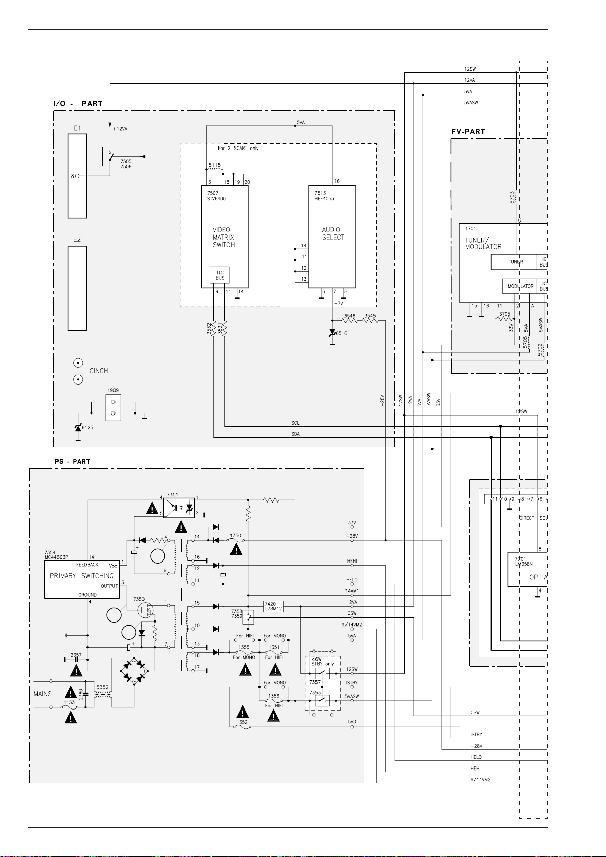
Platinenabbildungen und Schaltpläne / Layout of PCBs and Circuit Diagrams GV 27 …, GV 47 …, GV 7…
Blockschaltplan (Netzteil / Bus-System) / Block Circuit Diagram (Power Supply / Bus System)
EURO-AV
EURO-AV
3
1
2
4 - 4 GRUNDIG Service
 Loading...