

Page 1
CS100/CS300 Baery Operation
Quick Reference Guide
Note: This is an abbreviated guide
for proper baery operation and
maintenance for the CS100 and CS300.
For complete product instructions,
please refer to the CS100 and CS300
Operating Instructions.
Page 2
2
CS100/CS300 BATTERY OPERATION
Introduction
This Quick Reference Guide is designed to highlight the location,
functionality, alarms and maintenance of the lead acid batteries that
accompany the CS100 and CS300 Intra-aortic Ballon Pumps.
The CS100 and CS300 batteries are designed to be used during transport
or portable operation and it is critical to keep these batteries charged at
all times to avoid interruption in power during transport. Additionally, it is
important to maintain the batteries in accordance with CS100 and CS300
Operating Instructions.
Intro
CS100 CS300
Page 3

Table of Contents
Section Page #
Baery Overview 4-6
Baery Status 7-14
CS300 Baery Operation 15-20
CS300 Baery Preventive Maintenance 21
CS100 Baery Operation 22-30
CS100 Baery Preventive Maintenance 31
Key Baery Warnings and Cautions 32
CS100/CS300 BATTERY OPERATION
3
Table of Contents
Page 4

4
CS100/CS300 BATTERY OPERATION
CS100/CS300 Internal Battery Specifications
Type: 24 VDC (nominal), 17.2 Amp-hours
Sealed lead acid, maintenance free
Run Time: (full charge) 2.25 hours minimum (from full charge, 120 bpm, 22 ± 5 °C)
Approximately 3.0 hours typical with new baery (from full
charge, 90 bpm, 22 ± 5 °C)
NOTE: A reduction in runtime can occur over a baery's life for reasons such as age,
storage temperature and discharge depth.
Recharge Time: 18 hours minimum (from complete discharge to full charge,
22 ± 5 °C), 8 hours to achieve at least 90 percent charge
(typically).
Baery Overview
Page 5

CS100/CS300 Battery Information
CS100/CS300 Batteries
The IABP includes a battery pack which contains two sealed lead acid
batteries. The batteries are maintenance free. There is no need to add
water or electrolyte. The batteries are sealed to prevent leakage from the
terminals or case.
Replace batteries as required. Batteries should be replaced after 100 full
discharge cycles, at no more than three (3) year intervals, or if run time is
less than the minimum run time of 135 minutes minimum at 120 bpm.
Disposal of batteries should be conducted in accordance with local
statutes and the labeling shown on the battery pack.
CS100/CS300 BATTERY OPERATION
5
Baery Overview
Page 6

6
CS100/CS300 BATTERY OPERATION
CS100/CS300 Optimum Battery Performance
To obtain optimum battery performance and expected battery life the following guidelines should be observed.
• The batteries should be maintained at full charge when the IABP is not in use. It is required that the IABP be plugged
into an AC outlet when the system is not in use. Verify the battery is charging by observing the charge indicator on
the pump module. If the unit must be stored for an extended time period (2 months or longer} and AC power is not
available to maintain the internal battery, or if the unit is stored in an ambient exceeding the maximum operating
temperature, disconnect the system battery pack from the system console. Due to battery self-discharge the
disconnected batteries must be fully recharged at least every four months.
• The battery contains a safety vent that will allow gases to be released should its rating be exceeded. If this vent is
actuated do not operate the unit and contact a qualified service representative.
• Do not short circuit the battery or battery pack terminals. Keep battery pack covers on at all times to avoid objects or
liquids falling on batteries.
• Excessive heat is very detrimental to battery life. Do not operate the system in ambients above the maximum
operating temperature.
• DO NOT attempt to repair the battery. If the case is cracked or terminal leads are broken replace with the same
rate battery.
• DO NOT disassemble battery. The battery contains an electrolyte which can injure skin or damage clothing. In the
event that electrolyte gets on skin or in eyes, immediately flush with water for 15 minutes and get prompt medical
attention.
• Batteries must be replaced as pairs, (i.e., same lot/date code).
• When a Low Battery message is displayed after any system operation, the battery should be recharged within several
hours to prevent battery damage
Baery Overview
Page 7
It is extremely important to know the status of the IABP baeries at all times, as the status of the internal baeries affects the performance and
operation of the unit. There are two ways to determine the baery status, on the front panel and on the display screen.
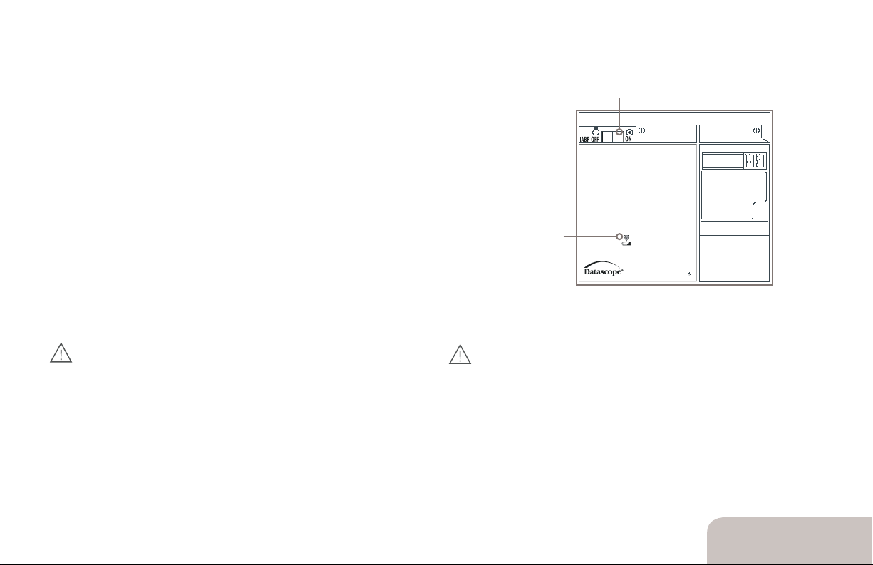
Viewing Battery Status on Front Panel
IABP ON/OFF
IABP ON/OFF
This is the ON/OFF switch for the IABP console and monitor module. Operation of
this switch does not affect the status of the internal baery charger.
Baery Charging LED
CS300
Automated Counterpulsation
INTELLISENSE TECHNOLO GY
This indicator has three states:
• It illuminates continuously when the internal baeries are fully charged
• The LED indicator flashes when the internal baeries are charging
Battery
Charging LED
• CS300: It is not illuminated when system is using the baery as a power source, or
when AC power is not available to the system, or when the system baery is faulty.
CS100: The Baery In Use status message and the Baery Indicator are displayed
Front Panel
when the system is operating from the internal rechargeable baery.
FOR CS300:
CAUTION: The system should be configured to charge the
internal baeries whenever AC power is available. Hence, keep the
system connected to a live AC receptacle with the Mains On/Off
switch in the “On“ position. If the system is to be stored for extensive
periods of time, or in ambient temperatures above the operating
range, see the Baery Section of the User Maintenance Chapter in
FOR CS100:
CAUTION: The internal baeries are charging only when the
AC Mains plug is connected to an active AC Mains source,
the AC Mains switch is “On”, and the baery charging status
LED is illuminated. This charging condition must be maintained
even when the system is not in use. Note that 18 hours of charging
is required to fully charge the baeries.
the Operating Instructions for additional information.
CAUTION: When AC power operation is intended, insure that the
system is plugged into AC mains, that the mains switch is in the “On”
position, and that the Baery in Use informational message in
NOT displayed.
CS100/CS300 BATTERY OPERATION
7
Baery Status
Page 8
8
CS100/CS300 BATTERY OPERATION
Baery Status
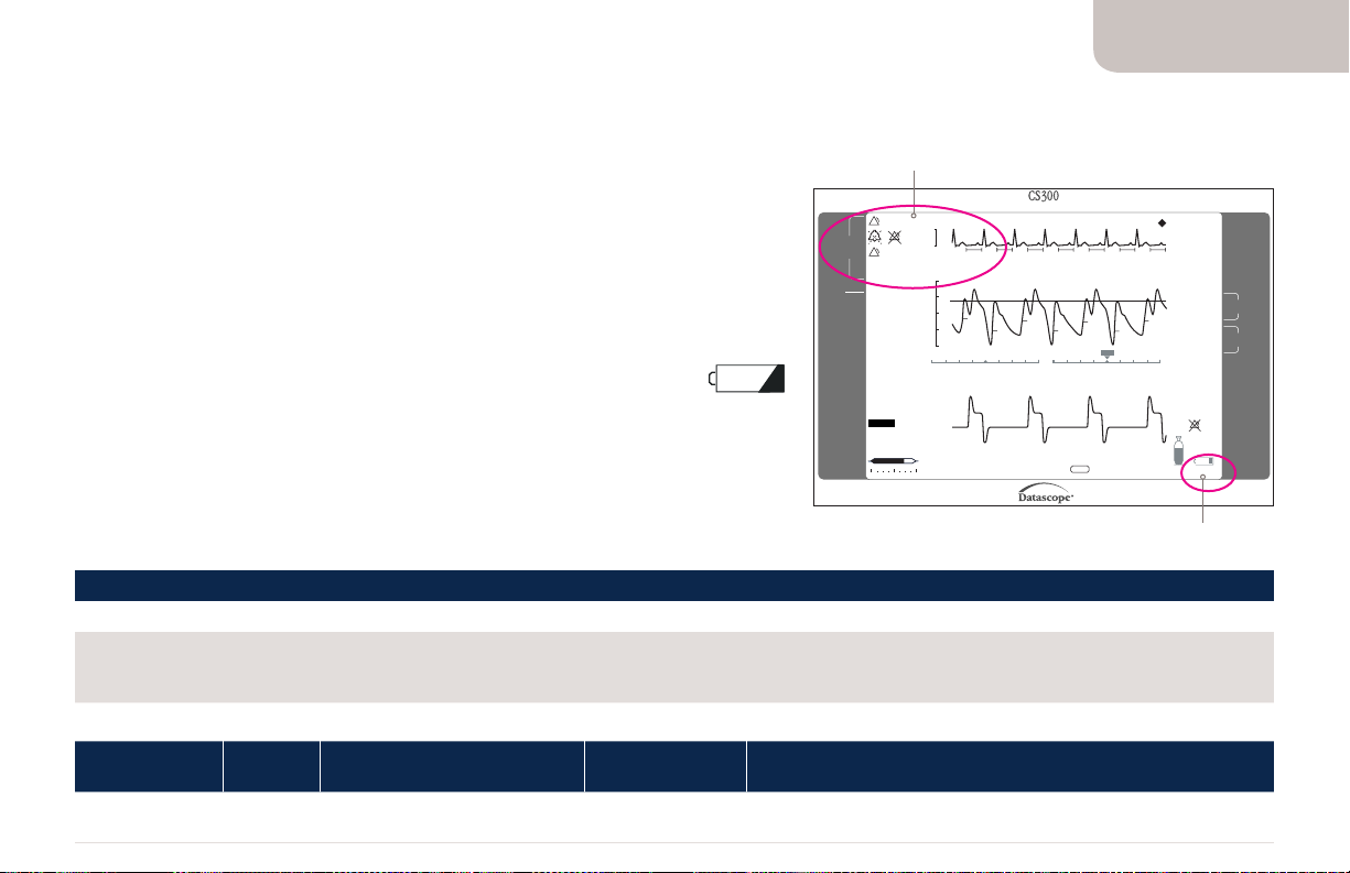
Viewing Battery Status on Display Screen
Alarm and Advisory Messages Area
This section of the screen displays alarm and advisory messages. The top-most line is reserved
for high priority alarms. The lower three (3) lines are shared to display any medium/low level
alarms or informational messages. If more than one message is displayed, they are posted in
priority order. See Alarms and Advisory Messages on page 9 of this document, for more
information regarding priority. As conditions are corrected, the corresponding message is
cleared and the next highest priority alarm or informational message is displayed. Pressing
the HELP key will access the appropriate help screen for the displayed condition. See “Help
Screens” in the Operating Instructions for more information.
Baery Indicator Icon
This icon indicates the approximate charge remaining in the internal baeries.
This indicator is displayed only when the system is powered by the internal baeries.
NOTE: The Low Baery Medium Priority Alarm is displayed when less than 30 minutes (approximately) of
internal baery life remains. When this message appears, the baery symbol is displayed as empty and
starts flashing. See the Troubleshooting and User Maintenance Chapters in the Operating Instructions for
additional information.
BATTERY IN USE
Associated Help Screen
Probable Cause Corrective Actions
The IABP is being powered from the
internal baeries.
CAUSE AND RESPONSE:
Operation
Trigger Mode
All All Indicates System is operating
Trigger
Source
Battery
1. Verify that it is necessary to operate from the internal baery. If appropriate, switch to the AC power source.
2. Verify MAINS power switch, located above the AC power cord connector, is ON.
Detailed Cause System Response Reset
Unaffected Message clears when power is received from AC power source.
from an internal baery.
Alarm & Advisory
Messages Area
Check IAB Catheter
!!!
ALARM &
ADVISORY
Low Battery
!!
MESSAGES
Auto Zeroing
Battery In Use
ECG
II
•
LEAD
Normal
•
GAIN
External
PRESSURE
SOURCE
IAB FILL MODE
Auto
SLOW GAS
On
ALARM
OPERATION
Auto
MODE
22 min in
Standby
IAB STATUS
Display Screen
Note: The display shown is for
illustrative purposes and does not
represent actual clinical conditions.
Automated Counterpulsation
0.5 mV
120
94
80
40
AUTO
Infl. Defl.
0.0
HELP
Available for Alarm/Advisory
TRIGGER
Pressure
19 mm Auto
Threshold
HEART RATE
bpm
80
SYSTOLIC
94
mmHg
Unassisted 99
DIASTOLIC
40
mmHg
Unassisted 51
MEAN
mmHg
72
AUG.
mmHg
115
AUG. ALARM
Off
mmHg
Battery
Helium
Battery
Indicator Icon
Page 9

Battery Alarms and Advisory Messages
The IABP utilizes both auditory and visual alarm signals to communicate the need for attention or awareness by the
pump operator. Auditory alarm signals (tone sequences) are primarily intended to attract the attention of the
operator. They were carefully developed to communicate the urgency of the response, as well as the pump’s location.
Auditory signals are effective over a relatively broad range of operator positions.
CAUTION: Do not set the alarm volume to such a low level that it cannot be readily heard over the ambient
noise level of the venue in which the IABP is used.
Visual alarm signals consist of both display panel symbols and text. The displayed information further reinforces the
urgency of the alarm (symbol shape, color & flashing property) and also identifies the alarm via a specific text
message. Textual information is legible at the operator’s position, up to 1 meter from the front of the display panel.
Additionally, alarms are further complimented by an option to display context sensitive help information to aid in the
understanding and guide in the resolution of the alarm condition.
Alarm and advisory messages are grouped into the following categories in order to facilitate operator awareness and
understanding:
• Technical Alarms
• High, Medium and Low Priority Alarms
• Informational Messages.
These messages are displayed based upon the priority of the condition(s) that prompted them. Technical Alarms and
High Priority Alarm messages are displayed in the top line of the Alarm and Advisory Messages section of the display.
Medium/low level alarms or informational messages are displayed in the 3 lines below the top line. When a Medium
Priority Alarm – such as a Battery Alarm – is displayed, IAB assist is not suspended and the Medium Priority Alarm
tone is sounded. Medium Priority Alarms require the Operator’s prompt response.
CS100/CS300 BATTERY OPERATION
9
Baery Status
Page 10

10
CS100/CS300 BATTERY OPERATION
!!
Medium Priority Alarms
Medium Priority Alarms indicate situations in which a prompt Operator
response is required. This class of alarm does not suspend pumping but
may indicate a need for corrective action. A yellow flashing alarm icon with
two (2) exclamation points denotes Medium Priority Alarms.
All Medium Priority Alarms have a uniform audio tone. The combination
of three (3) notes for Medium Priority Alarms is played in the following
sequence: three notes apause and then this cycle repeats.
NOTE: A “Low Battery” is categorized as a Medium Priority Alarm.
Baery Status
Medium Priority Alarm Icon
Page 11

Low Battery Alarm and Help Screen Message
Help screens are provided to guide the user through set-up procedures and for consultation regarding alarm
or informational message descriptions and alarm configuration. Help Screens are context sensitive and
available based on the information displayed on the screen. For example: The help screens for initial set-up
are only available at power-up and cleared once pumping is initiated. Similarly, the help screens for alarm
messages are only available while an alarm condition or informational message exists.
The following is the associated help screen for the battery-related Medium Priority Alarm:
LOW BATTERY
Associated Help Screen
Probable Cause Corrective Actions
There is less than 30 minutes of baery
operating time remaining.
CAUSE AND RESPONSE:
Operation
Trigger Mode
All All Baery reserve falls
Trigger
Source
Detailed Cause System Response Reset
below 30 minutes of
operating time.
1. Verify MAINS power switch, located above the AC power cord
connector, is ON.
2. Connect system to an AC power outlet.
Unaffected Automatically removes
message and turns
off tone when AC is
restored.
CS100/CS300 BATTERY OPERATION
11
Baery Status
Page 12

12
CS100/CS300 BATTERY OPERATION
Informational Messages
Informational Messages provide system information to the Operator. Informational Messages display textual
messages and, in some cases, are accompanied by an infrequently-repeating audio reminder tone.
The following are the associated help screens for battery-related Informational Messages:
BATTERY IN USE
Associated Help Screen
Probable Cause Corrective Actions
The IABP is being powered from the
internal baeries.
CAUSE AND RESPONSE:
Operation
Trigger Mode
All All Indicates System is
Trigger
Source
Detailed Cause System Response Reset
operating from an
internal baery.
1. Verify that it is necessary to operate from the internal baery.
If appropriate, switch to the AC power source.
2. Verify MAINS power switch, located above the AC power cord
connector, is ON.
Unaffected Message clears when
power is received from
AC power source.
Baery Status
Page 13

Informational Messages
BATTERY MAINTENANCE REQUIRED
Associated Help Screen
Probable Cause Corrective Actions
The IABP internal baery requires
maintenance.
CAUSE AND RESPONSE:
Operation
Mode
All All The Baery Test Due Date
Trigger
Source
Detailed Cause System Response Reset
or Baery Replacement
Date predate the current
system date at startup
or the internal baery
has a total accumulated
discharge time in excess of
100 total discharge cycles.
1. Contact Getinge Service.
2. Continue operation on AC power.
3. If baery operation is necessary, baery run time may be
reduced. Monitor the system for a Low Baery alarm.
NOTE: If a Low Baery alarm occurs, immediately connect the
system to AC power.
None At startup the message
is cleared when the
START key is pressed.
During operation the
message is removed
aer 30 seconds.
CS100/CS300 BATTERY OPERATION
13
Baery Status
Page 14

14
CS100/CS300 BATTERY OPERATION
Informational Messages
BATTERY MAINTENANCE REQUIRED
Associated Help Screen
Probable Cause Corrective Actions
The internal baery has become
unreliable.
CAUSE AND RESPONSE:
Operation
Mode
All All The internal baery failed
Trigger
Source
Detailed Cause System Response Reset
to reach a satisfactory level
of charge within 10 hours.
1. Contact Getinge Service. Baery replacement may
be required.
2. Continue operation on AC power.
3. If baery operation is necessary, baery run time may be
reduced. Monitor the system for a Low Baery alarm.
NOTE: If a Low Baery alarm occurs, immediately connect the
system to AC power.
Baery Status
None At startup the message
is cleared when the
START key is pressed.
During operation the
message is removed
aer 1 minute.
Page 15

Introduction for CS300
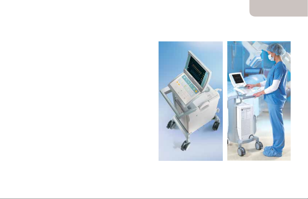
The IABP is available in two versions: the ‘Standard’ or ‘Hospital’ version,
which is optimized for in-hospital usage; and the UTS (Universal Transport
System! version, which is optimized for vehicular transport. The differences
between the two versions are described later in this chapter. Both versions
have the same therapeutic capabilities, and both have built-in battery packs,
which automatically power the unit if AC power is not available
CS300 Hospital Cart
The IABP console is mounted on a hospital cart for intra-hospital transport.
The console may be separated from the cart to accommodate very tight
spaces within a hospital room/venue.
All four (4) casters on the hospital cart swivel to facilitate movement in any
direction. The two casters closest to the cart handle are multifunctional.
They can be locked in the straight position (directional lock) or used as a
brake (total lock). The two casters on the side opposite the handle have
total lock only. It is recommended that all four casters are locked for use on
uneven surfaces or in transport vehicles.
IABP Console on a
Hospital Cart
CS100/CS300 BATTERY OPERATION
15
CS300 Baery
Operation
Page 16

16
CS100/CS300 BATTERY OPERATION
CS300 Portable Operation
The following is recommended by Datascope:
1. Battery fully charged prior to starting transport.
2. The use of Datascope’s Sensor IAB will eliminate the pressure waveform artifact that commonly occurs when moving patients
using conventional fluid-filled pressure monitoring catheters. Altitude changes are compensated for automatically in the
Autofill mode or manually in the Manual Fill mode.
3. The system must be properly secured when used in an ambulance, helicopter, or fixed wing aircraft.
The Universal Transport System (UTS) is specifically designed for air and vehicular transport. The UTS version mechanically
attaches to a docking station for high strength mounting.
WARNING: The user should continually rely on visual alarm messages during high noise transport situations.
CS300 Baery
Operation
Page 17

CS300 Battery Operation
The system automatically switches to battery power if AC power is not available (intentionally or due to power
loss). When AC power is restored, the system automatically reverts from internal battery operation to AC Mains
usage. The internal battery pack charges while the system operates from AC Mains power.
Prior to portable operation, the battery should be fully charged. A fully charged battery is indicated by a
continuously illuminated battery-charging LED (located on the front panel).
WARNING: Disconnecting the internal battery, when AC mains are not connected, will stop the therapy,
(i.e., power down the pump.)
CAUTION: When AC power operation is intended, insure that the system is plugged into AC mains, that the
mains switch is in the “On” position, and that the “Battery in Use” informational message is NOT displayed.
CAUTION: System batteries must be properly maintained and periodically tested.
CAUTION: The system should be configured to charge the internal batteries whenever AC power is
available. Hence, keep the system connected to a live AC receptacle with the Mains On/Off switch in
the On position. If the system is to be stored for extensive periods of time, or in ambient temperatures
above the operating range, see the Battery Section of the User Maintenance Chapter in the Operating
Instructions for additional information.
CS100/CS300 BATTERY OPERATION
17
CS300 Baery
Operation
Page 18

18
CS100/CS300 BATTERY OPERATION
CS300 Battery Operation
Battery in Use
• Verify that the “Battery in Use” Informational Message and the Battery Indicator are displayed
when in battery operation.
• Battery charging is not active when the battery is in use.
• When the battery has approximately 30 minutes of operating time remaining, the following occurs:
• The Medium Priority Alarm tone is activated.
• The “Low Battery” Medium Priority Alarm message is displayed on the screen continuously.
• The Battery Indicator is displayed as empty and it starts flashing.
• The condensate removal module will not operate (to conserve remaining power).
A reduction in run time will occur over a battery’s life due to age, storage temperature and discharge cycles.
Batteries which are continually subjected to complete discharge cycles without the recommended
immediate recharging, can incur permanent damage.
CS300 Baery
Operation
Page 19

CS300 Operation from DC-to-AC Inverter
The IABP can be powered from a DC-to-AC inverter if the DC source and the inverter meet the specifications
defined below. The DC source and inverter should be checked for proper operation by qualified maintenance
personnel prior to emergency use. The message Battery in Use will not be displayed during proper AC
inverter operation.
Specifications for DC Source and Inverter for Use with the IABP
Voltage Output: 100-120/220-240 VAC ± l 0%
Frequency: 50 Hz ±2 Hz, 60 Hz ±2 Hz
Overshoots: Does not continuously generate overshoots greater than 375
Volts peak with widths greater than 10 mSec when powering the system
Waveform: Sine wave or modified sine wave
Output Capability: Minimum of 500 watts continuous power; 1000 watts surge power
Safety Compliance: Meets or exceeds safety standards per IEC 60601-1
CS100/CS300 BATTERY OPERATION
19
CS300 Baery
Operation
Page 20

20
CS100/CS300 BATTERY OPERATION
Removing CS300 Pump Console from the Cart
(with battery pack attached)
The console can be removed from the cart with or without the battery pack attached. Removing the console
without the battery pack attached reduces the lift weight by approximately 35 lbs.
CAUTION: Insure that the wheels of the cart are in the locked position when removing the pump console
from the cart or returning the pump console to the cart.
CS300 Baery
Operation
Unlock console by
pressing tab to right
of console release
handle and pull
handle straight out.
CAUTION: When transporting the system without
the cart, be sure to only pull the system by the
handle, DO NOT PUSH.
2 3 41
Lift pump console
straight up and off
cart.
Release button
Detach monitor
from cart handle
by pressing button
on rear of monitor.
PULL
Attach monitor to top
of pump console. Extend
console handle until it
locks, tilt pump and pull
to transport.
CAUTION: The pull up handle must not be used
to lift the unit. Use only designated lift points
and handles.
Page 21

CS300 Preventive Maintenance
Two preventive maintenance schedules have been provided.
Schedule A indicates which actions should be taken by either the Clinical User or by a Biomedical Technician IBMET). These steps do not
require the use of tools and may be performed in a clinical seing.
Schedule B indicates the actions which should be performed only by a BMET or other qualified service personnel. Tools are required and in
some cases the instrument covers must be removed.
WARNING: Preventive Maintenance should not be performed when the IABP is aached to a patient.
CAUTION: This product requires scheduled preventative maintenance in order to maintain its specified performance. Note that
maintenance includes periodic cleaning to assure that proper cooling airflow of the system‘s electronics is maintained.
Schedule A
To be performed by the clinical user or the BMET.
INTERVAL
Required Action Before or Aer
Before each use, ensure that the
Baery Charging LED is illuminated;
or, if baeries are in use, that the
Baery Icon shows a full baery. See
page 7 of this document.
* Whichever comes first
CS100/CS300 BATTERY OPERATION
21
Each Use
•
Every
Month
Every 6
Months
Every
1000 Hrs.
of Use or
2 Years*
Schedule B
To be performed by the BMET.
INTERVAL
Required Action
(REFER TO SERVICE MANUAL)
check baery for rated voltage and
check baery run time. Replace
baeries when operating time is
marginal or aer three (3) years.*
* This does not imply a three-year warranty.
ery 6
Ev
Months
Every
2500
Hours
Every
5000
Hours
•
CS300 Baery
Preventive Maintenance
Page 22

22
CS100/CS300 BATTERY OPERATION
CS100 Hospital Cart
The CS100 console is mounted on a hospital cart for intra-hospital
transport. The console may be separated from the cart to accommodate
very tight spaces within a hospital room/venue.
All four (4) casters on the hospital cart swivel to facilitate movement in any
direction. The two casters closest to the cart handle are multifunctional.
They can be locked in the straight position (directional lock) or used as a
brake (total lock). The two casters on the side opposite the handle have
total lock only.
NOTE: The casters on the handle side of the cart may or may not have a
braking feature. Refer to markings on the casters.
It is recommended that all four casters are locked for use on uneven
surfaces or in transport vehicles.
CS100 Baery
Operation
CS100 Console on a
Hospital Cart
Page 23

CS100 Portable Operation
The following is recommended by Datascope during portable operation:
1. Baery fully charged prior to starting transport.
2. Altitude changes are compensated for automatically in the Autofill mode or manually in the Manual Fill mode.
3. The system must be properly secured when used in an ambulance, helicopter, or fixed wing aircra.
The CS100 is available in two versions with identical clinical functionality. A console version with a hospital cart
or the CS100 Universal Transport System (UTS) is specifically designed for air and vehicular transport. The UTS
version mechanically aaches to a docking station for high strength mounting.
WARNING: The user should continually rely on visual alarm messages during high noise transport
situations. The “Flash Alarms” option should be turned ON to improve the visibility of alarm messages.
This option can be set in the User Preferences Menu (located in the Display Preferences submenu.)
CS100/CS300 BATTERY OPERATION
23
CS100 Baery
Operation
Page 24

24
CS100/CS300 BATTERY OPERATION
CS100 Battery Operation
During portable operation, the CS100 is powered by a rechargeable baery. Prior to
portable operation the baery should be fully charged. A fully charged baery is
indicated by a continuously illuminated baery charging LED. This LED is located
on the front panel.
The Baery In Use status message and the Baery Indicator are displayed when the
CS100 is operating from the internal rechargeable baery. When the baery has
approximately 30 minutes of operating time remaining, the following occurs:
• An audible double beep alarm is activated for 30 seconds
• The Low Baery or Low Baery (EXT) (CS l 00i only) alert messages are displayed
on the screen continuously
• The Baery Indicator is displayed as empty and it starts flashing
• The condensate removal module will not operate
CS100 Baery
Operation
Page 25

CS100 Battery Charging
To charge the internal baery:
1. Leave the system power cord plugged in and set the MAINS On/Off to ON.
2. Check that the Baery Charging LED is illuminated (continuously or flashing depending on state).
3. Allow a minimum of l 8 hours to fully charge a low baery. Allow 8 hours to achieve al least 90 percent
charge (typically).
4. A fully-charged new internal baery will provide at least 135 minutes of portable operation.
NOTE: A reduction in run time will occur over a baery‘s life due to age, storage temperature and
discharge depth. Baeries which are continually subjected to complete discharge cycles without the
recommended immediate recharging, can incur permanent damage.
CS100/CS300 BATTERY OPERATION
25
CS100 Baery
Operation
Page 26

26
CS100/CS300 BATTERY OPERATION
CS100 Switching from AC to Battery Operation
1. The system automatically switches to baery power if AC power is removed (intentionally
or due to power loss).
2. If necessary, charge the baery as described in accordance with previous instructions.
3. Verify that the BATTERY IN USE advisory message and the Baery Indicator are displayed.
NOTE: Baery charging is not active in this state.
4. When AC power is restored the system automatically reverts from internal baery
operation to AC Mains usage. The internal baery pack will resume charging while the
system operates from AC Mains power. Always verify that the Baery Charging LED is
continuously illuminated or flashing.
CS100 Baery
Operation
Page 27

Operation From External DC Source (CS1OOi only)
In this case, the System is to be powered from an external DC source such as may be
available from an ambulance, helicopter, or external baery pack.
1. Connect a voltage-compatible external source to the External DC Input connector.
2. Internal baery will not be charged in this mode.
3. The IABP ON/OFF switch will activate the system.
4. Interruption of the external DC source power will result in portable internal baery
operation.
5. The internal BATTERY INDICATOR will not be displayed during external DC operation.
CS100/CS300 BATTERY OPERATION
27
CS100 Baery
Operation
Page 28

28
CS100/CS300 BATTERY OPERATION
Operation from DC-to-AC Inverter
The CS100 can be powered from a DC-to-AC inverter if the DC source and the inverter meet
the specifications defined below. The DC source and inverter should be checked for proper
operation by qualified maintenance personnel prior to emergency use. The message Baery
in Use will not be displayed during proper AC inverter operation.
Specifications for DC Source and Inverter for Use with the CS100
Voltage Output: 100-120/220-240 VAC ± 10%
Frequency: 50 Hz ±2 Hz, 60 Hz ±2 Hz
Overshoots: Does not continuously generate overshoots greater than
375. Volts peak with widths greater than 10 mSec when
powering the system.
Waveform: Sine wave or modified sine wave
Output Capability: Minimum of 500 was continuous power; 1000 was
surge power
Safety Compliance: Meets or exceeds safety standards per IEC 60601-1.
CS100 Baery
Operation
Page 29

Portable Operation Emergency Battery Back Up Recommendations
Datascope recommends that a back-up to the internal baery always be available.
WARNING: Replacing the internal baery, when AC mains are not connected, will
stop the therapy, (i.e., power down the pump.)
CS100/CS300 BATTERY OPERATION
29
CS100 Baery
Operation
Page 30

30
CS100/CS300 BATTERY OPERATION
Push down
to release
Removing CS100 Pump Console from the Cart
(with battery pack attached)
The console can be removed from the cart with or without the battery pack attached. Removing the console
without the battery pack attached reduces the lift weight by approximately 35 lbs.
CAUTION: Insure that the wheels of the cart are in the locked position when removing the pump
console from the cart or returning the pump console to the cart.
CS100 Baery
Operation
Unlock console by
pressing tab to right
of console release
handle and pull
handle straight out.
2 3 41
Lift pump console
straight up and
off cart.
Push to
Detach
Detach monitor
from cart handle by
pressing button on
rear of monitor.
PULL
Attach monitor to top
of pump console. Extend
console handle until it
locks, tilt pump and pull
to transport.
Page 31

CS100/100i Preventive Maintenance
Two preventive maintenance schedules have been provided.
Schedule A indicates which actions should be taken by either the Clinical User or by a Biomedical Technician (BMET). These
steps do not require the use of tools and may be performed in a clinical seing.
Schedule B indicates the actions which should be performed only by a BMET or other qualified service personnel. Tools are
required and in some cases the instrument covers must be removed.
WARNING: Preventive Maintenance should not be performed when the IABP is aached to a patient.
Schedule A
To be performed by the clinical user or the BMET.
INTERVAL
Required Action Before or Aer
Check baery system
Check Baery Indicator
Check baery run time. Replace
baeries when operating time is
marginal.
* Whichever comes first.
CS100/CS300 BATTERY OPERATION
31
Each Use
•
Every
Month
Every 6
Months
•
Every
1000 Hrs.
of Use or
2 Years
Schedule B
To be performed by the BMET.
INTERVAL
Required Action
(REFER TO SERVICE MANUAL)
Check baery for rated voltage and
check baery run time. Replace
baeries when operating time is
marginal or aer three (3) years.
* This does not imply a three-year warranty.
Every 6
Mon
ths
Every
2500
Hours
Every
5000
Hours
•
CS100 Baery
Preventive Maintenance
Page 32

32
CS100/CS300 BATTERY OPERATION
Warnings and Precautions
WARNING: The patient balloon should not remain inactive in the patient (i.e., no inflating and deflating) for more than 30
minutes, due to the potential for thrombus formation.
CAUTION: The internal baeries are charging only when the AC Mains plug is connected to an active AC Mains source,
the AC Mains switch is ON, and the baery charging status LED is illuminated. This charging condition must be maintained even when the system is not in use.
CAUTION: System baeries must be properly maintained and periodically tested.
CAUTION: The system should be configured to charge the internal baeries whenever AC power is available. Hence, keep
the system connected to a live AC receptacle with the Mains On/Off switch in the On position. If the system is to be
stored for extensive periods of time, or in ambient temperatures above the operating range, see the Baery Section of the
User Maintenance Chapter
CAUTION: Prior to emergency use, when the system is to be powered from an AC inverter, the inverter should be checked
for proper operation with the system by qualified maintenance personnel. The message “Baery in Use” will not be
displayed during proper AC inverter operation.
CAUTION: When the optional Protective Cover is on, do not leave the IABP on and powered-up (i.e., with the IABP On/Off
switch in the ON position).
in the Operating Instructions for additional information
Key Baery
Warnings & Precautions
.
Page 33

Page 34

PN: 00 02-08- 9867 Rev A · MCV0 0091613 RE VA · * , Ge tinge, and M aquet are tra demarks or r egistere d trademar ks of Getinge A B, its
subsi diaries, or a ffiliates in th e United Sta tes or other c ountries · Ma quet is regi stered wi th the U.S. Pa tent and Tradema rk Office · STATLOCK is a
regis tered tra demark of C. R. Bard, In c. · Copyrig ht 2019 Datas cope Corp . · All rights r eserved · C AUTION : Federal (U. S.A.) law r estrict s this devic e
to sale , distribu tion and use b y or on the orde r of a physicia n. Refer to Ins tructio ns for Use for cu rrent indi cations, wa rnings, c ontraindi cations
and pre cautions · 0 5/2019
Getinge •
1300 MacArthur Blvd., Mahwah, NJ 07430
45 Barbour Pond Drive, Wayne, NJ 07470 ·
·
USA
·
+1 201 995-8700 or
USA
·
+1 888 880-2874
1 800 777-4222
www.getinge.com
 Loading...