


OPERATOR MANUAL
61301608206 Rev. C
400LS/500LS
SERIES
STEAM STERILIZERS


OPERATOR MANUAL
400LS/500LS Series
Steam Sterilizers
Getinge USA, Inc.
1777 East Henrietta Road
Rochester, New York 14623-3133 USA
Phone: (800) 950-9912
Facsimile: (800) 950-2570
OPERATOR MANUAL 61301608206
Rev. A (02/2002)
Rev. B (01/2003)
Rev. C (09/2005)
Related Publications:
Manual 400LS/500LS Series
Installation Instructions 61301608205
Supervisor Manuall 61301608207
Service Manual 61301608209
Parts Catalog 61301608210
DESCRIPTION OF SYMBOLS & NOTES IN MANUAL
The following symbols with related notes appear in this manual.
“Warning” notes alert the user to the possibility of personal injury.
WARNING
WARNING
CAUTION
NOTE
NOTES
CAUTION
“Caution” notes alert the user to the possibility of damage to the equipment.
“Notes” alert the user to pertinent facts and conditions.
• This manual contains proprietary information of Getinge USA, Inc. It shall
not be reproduced in whole or in part without the written permission of
Getinge USA, Inc.
• This manual is intended for qualified technicians with specialized training.
If you require additional help, contact the company service representative.
• POSSIBILITY OF INJURY: Misuse of equipment or
bypassing its safety features may result in personal injury.
• POSSIBILITY OF EQUIPMENT DAMAGE: Misuse of
equipment may result in equipment damage.
• The 400LS/500LS Series Steam Sterilizers are designed
to steam sterilize laboratory goods and solutions.
This equipment is NOT intended for use other than
expressly stated.
Getinge® is a registered trademark.
Copyright ©2005 by Getinge USA, Inc.
Biosign®, EZ-VU™ Test Pack—registration pending
ii

SPECIAL SAFETY INSTRUCTIONS . . . . . . . . . . . . . . . . . . . ix
DESCRIPTION OF SYMBOLS ON THE EQUIPMENT . . . . xv
Switches. . . . . . . . . . . . . . . . . . . . . . . . . . . . . . . . . . . . . xv
Indicators . . . . . . . . . . . . . . . . . . . . . . . . . . . . . . . . . . . . xv
Labels . . . . . . . . . . . . . . . . . . . . . . . . . . . . . . . . . . . . . . xvi
MANUAL CONVENTIONS . . . . . . . . . . . . . . . . . . . . . . . . . xvii
Section 1 Getting Started
MODELS . . . . . . . . . . . . . . . . . . . . . . . . . . . . . . . . . . . . . . 1–1
CONTROLS AND INDICATORS . . . . . . . . . . . . . . . . . . . . 1–2
CYCLE ASSIGNMENTS . . . . . . . . . . . . . . . . . . . . . . . . . . 1–7
Section 2 Control Panel Navigation
PROCESS SCREENS . . . . . . . . . . . . . . . . . . . . . . . . . . . . 2–2
Bar Graph Screen . . . . . . . . . . . . . . . . . . . . . . . . . . . . 2–2
Details Screen . . . . . . . . . . . . . . . . . . . . . . . . . . . . . . . 2–3
The Plot Graph Screen . . . . . . . . . . . . . . . . . . . . . . . . 2–4
Selecting a Process Screen. . . . . . . . . . . . . . . . . . . . . 2–4
SOFTKEYS . . . . . . . . . . . . . . . . . . . . . . . . . . . . . . . . . . . . 2–6
TURNING ON THE CONTROLS . . . . . . . . . . . . . . . . . . . . 2–7
NAVIGATION BASICS. . . . . . . . . . . . . . . . . . . . . . . . . . . . 2–8
Directional Arrows . . . . . . . . . . . . . . . . . . . . . . . . . . . . 2–8
ENTER. . . . . . . . . . . . . . . . . . . . . . . . . . . . . . . . . . . . . 2–8
Select an Item from a List . . . . . . . . . . . . . . . . . . . . . . 2–8
Enter an Alphanumeric Value . . . . . . . . . . . . . . . . . . . 2–9
Communicating With the System. . . . . . . . . . . . . . . . 2–10
Exit from a Screen . . . . . . . . . . . . . . . . . . . . . . . . . . . 2–11
Table of Contents
Entering Data in Dialog Boxes . . . . . . . . . . . . . . 2–10
Responding to Yes/No Message Boxes . . . . . . . 2–10
iii

Section 3 Preparation for Use
DAILY CHECKLIST . . . . . . . . . . . . . . . . . . . . . . . . . . . . . . 3–1
LOAD PREPARATION. . . . . . . . . . . . . . . . . . . . . . . . . . . . 3–2
TECHNIQUES FOR LOADING . . . . . . . . . . . . . . . . . . . . . 3–4
LOADING ACCESSORIES . . . . . . . . . . . . . . . . . . . . . . . . 3–9
Section 4 Operating Instructions
SEQUENCE OF OPERATION. . . . . . . . . . . . . . . . . . . . . . 4–1
OPERATING THE STERILIZER . . . . . . . . . . . . . . . . . . . . 4–2
OPENING AND CLOSING THE STERILIZER DOOR. . . 4–15
OPERATING THE PRINTER. . . . . . . . . . . . . . . . . . . . . . 4–19
Operational Readiness . . . . . . . . . . . . . . . . . . . . . . . . 3–1
End of Cycle Routine. . . . . . . . . . . . . . . . . . . . . . . . . . 3–5
Liquid RTD Placement (Option). . . . . . . . . . . . . . . . . . 3–7
Loading Car and Transfer Carriage (533LS only) . . . . 3–9
Rack and Extendable Shelves. . . . . . . . . . . . . . . . . . 3–12
Turning on the Controls. . . . . . . . . . . . . . . . . . . . . . . . 4–2
Previewing/Selecting a Cycle . . . . . . . . . . . . . . . . . . . 4–2
Loading the Sterilizer. . . . . . . . . . . . . . . . . . . . . . . . . . 4–5
Editing Cycle Parameters . . . . . . . . . . . . . . . . . . . . . . 4–6
Starting a Cycle . . . . . . . . . . . . . . . . . . . . . . . . . . . . . . 4–7
Canceling a Cycle (Manual Abort). . . . . . . . . . . . . . . . 4–9
End of Cycle Routine. . . . . . . . . . . . . . . . . . . . . . . . . 4–10
Unloading the Sterilizer . . . . . . . . . . . . . . . . . . . . . . . 4–12
Safety Features . . . . . . . . . . . . . . . . . . . . . . . . . . . . . 4–16
Manual Door . . . . . . . . . . . . . . . . . . . . . . . . . . . . . . . 4–16
Power Door (Option) . . . . . . . . . . . . . . . . . . . . . . . . . 4–18
STATUS Indicator . . . . . . . . . . . . . . . . . . . . . . . . . . . 4–20
Advancing the Paper. . . . . . . . . . . . . . . . . . . . . . . . . 4–20
Using the Lever . . . . . . . . . . . . . . . . . . . . . . . . . . . . . 4–21
Saving Printouts . . . . . . . . . . . . . . . . . . . . . . . . . . . . 4–21
Tearing Off Printer Paper . . . . . . . . . . . . . . . . . . . . . 4–21
Replacing the Printer Paper . . . . . . . . . . . . . . . . . . . 4–21
Removing the Take-up Core . . . . . . . . . . . . . . . . . . . 4–23
Inserting a New Core. . . . . . . . . . . . . . . . . . . . . . . . . 4–23
Inserting a New Roll . . . . . . . . . . . . . . . . . . . . . . . . . 4–23
Loading the Paper. . . . . . . . . . . . . . . . . . . . . . . . . . . 4–23
Storing and Handling Paper Rolls . . . . . . . . . . . . . . . 4–24
Printing a Duplicate Record. . . . . . . . . . . . . . . . . . . . 4–24
iv

READING THE CYCLE PRINTOUT. . . . . . . . . . . . . . . . . 4–25
Cycle Start and Parameters. . . . . . . . . . . . . . . . . . . . 4–25
Phases. . . . . . . . . . . . . . . . . . . . . . . . . . . . . . . . . . . . 4–25
Validating the Exposure Phase . . . . . . . . . . . . . . . . . 4–26
PERFORMANCE TESTING. . . . . . . . . . . . . . . . . . . . . . . 4–28
Biological Monitoring . . . . . . . . . . . . . . . . . . . . . . . . . 4–28
Vacuum Leak Test. . . . . . . . . . . . . . . . . . . . . . . . . . . 4–29
Section 5 Conditional Instructions
CANCELING A CYCLE (MANUAL ABORT) . . . . . . . . . . . 5–2
Timed Phase . . . . . . . . . . . . . . . . . . . . . . . . . . . . . . . . 5–3
Untimed Phase . . . . . . . . . . . . . . . . . . . . . . . . . . . . . . 5–4
ADVANCING A CYCLE . . . . . . . . . . . . . . . . . . . . . . . . . . . 5–6
END OF CYCLE ROUTINE . . . . . . . . . . . . . . . . . . . . . . . . 5–9
SHUTTING DOWN THE STERILIZER. . . . . . . . . . . . . . . 5–11
Turning Off Electrical Power . . . . . . . . . . . . . . . . . . . 5–11
Turning Off the Steam and Water Supplies. . . . . . . . 5–12
RECOVERING FROM ELECTRICAL POWER FAILURE 5–13
Power Failure During Standby. . . . . . . . . . . . . . . . . . 5–14
Power Failure During a Cycle . . . . . . . . . . . . . . . . . . 5–14
OPENING THE DOOR MANUALLY. . . . . . . . . . . . . . . . . 5–15
Preparation . . . . . . . . . . . . . . . . . . . . . . . . . . . . . . . . 5–16
Remove Pressure from the Gasket . . . . . . . . . . . . . . 5–18
Remove the Load. . . . . . . . . . . . . . . . . . . . . . . . . . . . 5–21
Restore Pressure to the Gasket. . . . . . . . . . . . . . . . . 5–21
CYCLE END . . . . . . . . . . . . . . . . . . . . . . . . . . . . 4–26
CYCLE RESULTS . . . . . . . . . . . . . . . . . . . . . . . . 4–26
Section 6 Display Messages
DIAGNOSTIC MESSAGE TYPES. . . . . . . . . . . . . . . . . . . 6–2
Failure Conditions . . . . . . . . . . . . . . . . . . . . . . . . . . . . 6–2
Fault Conditions. . . . . . . . . . . . . . . . . . . . . . . . . . . . . . 6–4
Informational Messages. . . . . . . . . . . . . . . . . . . . . . . . 6–5
Visual Alarms. . . . . . . . . . . . . . . . . . . . . . . . . . . . . . . . 6–6
TROUBLESHOOTING . . . . . . . . . . . . . . . . . . . . . . . . . . . . 6–7
DIAGNOSTIC MESSAGES . . . . . . . . . . . . . . . . . . . . . . . . 6–8
v

Section 7 Routine Maintenance
MAINTENANCE SCHEDULE . . . . . . . . . . . . . . . . . . . . . . 7–1
DAILY. . . . . . . . . . . . . . . . . . . . . . . . . . . . . . . . . . . . . . . . . 7–2
WEEKLY . . . . . . . . . . . . . . . . . . . . . . . . . . . . . . . . . . . . . . 7–4
EVERY THREE MONTHS . . . . . . . . . . . . . . . . . . . . . . . . . 7–6
WHEN REQUIRED . . . . . . . . . . . . . . . . . . . . . . . . . . . . . . 7–8
Cleaning the Sediment Screens . . . . . . . . . . . . . . . . . 7–2
Blowing Down the Steam Boiler (option). . . . . . . . . . . 7–3
Cleaning the Exterior Surfaces . . . . . . . . . . . . . . . . . . 7–4
Cleaning theChamber Interior . . . . . . . . . . . . . . . . . . . 7–4
Cleaning the Accessories . . . . . . . . . . . . . . . . . . . . . . 7–4
Cleaning Materials . . . . . . . . . . . . . . . . . . . . . . . . 7–5
Cleaning Agents . . . . . . . . . . . . . . . . . . . . . . . . . . 7–5
Cleaning Methods. . . . . . . . . . . . . . . . . . . . . . . . . 7–5
Checking the Pressure Relief Valves . . . . . . . . . . . . . 7–6
Jacket Pressure Relief Valve . . . . . . . . . . . . . . . . 7–6
Chamber Pressure Relief Valve . . . . . . . . . . . . . . 7–7
Cleaning the Steam and Water Strainers . . . . . . . . . . 7–7
Cleaning the Door Gasket(s). . . . . . . . . . . . . . . . . . . . 7–8
Replacing the Door Gasket(s). . . . . . . . . . . . . . . . . . . 7–9
Replacing the Air Filter . . . . . . . . . . . . . . . . . . . . . . . 7–12
Resetting the Clock . . . . . . . . . . . . . . . . . . . . . . . . . . 7–13
Installing/Removing, & Adjusting Shelf Racks. . . . . . 7–15
Installing the Shelves . . . . . . . . . . . . . . . . . . . . . 7–15
Removing the Shelves . . . . . . . . . . . . . . . . . . . . 7–16
Changing the Rack Height . . . . . . . . . . . . . . . . . 7–17
Section 8 Steam Boiler
GENERAL DESCRIPTION . . . . . . . . . . . . . . . . . . . . . . . . 8–1
WATER QUALITY INFORMATION . . . . . . . . . . . . . . . . . . 8–2
Required Feedwater Quality . . . . . . . . . . . . . . . . . . . . 8–2
Feedwater Quality Recommendations . . . . . . . . . . . . 8–3
Recommended Limits Within a Boiler . . . . . . . . . . . . . 8–3
MANUAL BLOW-DOWN . . . . . . . . . . . . . . . . . . . . . . . . . . 8–4
AUTOMATIC BLOW-DOWN PACKAGE (OPTION) . . . . . 8–7
Setting Up Auto Blow-Down . . . . . . . . . . . . . . . . . . . . 8–8
SERVICE MAINTENANCE . . . . . . . . . . . . . . . . . . . . . . . . 8–9
Section 9 Utilities Control Feature
vi

Section 10 Uninterruptible Power Supply
GENERAL DESCRIPTION. . . . . . . . . . . . . . . . . . . . . . . . 10–1
OPERATION . . . . . . . . . . . . . . . . . . . . . . . . . . . . . . . . . . 10–3
Standby Mode . . . . . . . . . . . . . . . . . . . . . . . . . . . . . . 10–3
Normal Mode . . . . . . . . . . . . . . . . . . . . . . . . . . . . . . . 10–3
Battery Mode . . . . . . . . . . . . . . . . . . . . . . . . . . . . . . . 10–4
ROUTINE MAINTENANCE . . . . . . . . . . . . . . . . . . . . . . . 10–5
Cleaning (Weekly) . . . . . . . . . . . . . . . . . . . . . . . . . . . 10–5
Testing (Weekly) . . . . . . . . . . . . . . . . . . . . . . . . . . . . 10–5
Replacing Battery. . . . . . . . . . . . . . . . . . . . . . . . . . . . 10–5
Section 11 Unidirectional Double Doors
Door Operation . . . . . . . . . . . . . . . . . . . . . . . . . . . . . 11–1
Section 12 Liquid RTD Package
THEORY OF OPERATION . . . . . . . . . . . . . . . . . . . . . . . 12–2
Exposure Timing Based on the Chamber Temperature
(F0 set to zero (disabled)). . . . . . . . . . . . . . . . . . 12–3
Exposure Timing Based on the F0 Value . . . . . . . . . 12–3
Appendix A Consumable Stock and Spare Parts
CONSUMABLE STOCK. . . . . . . . . . . . . . . . . . . . . . . . . . . A–1
SPARE PARTS . . . . . . . . . . . . . . . . . . . . . . . . . . . . . . . . . A–2
Appendix B Menu Tree
Glossary
Index
vii

viii

SPECIAL SAFETY INSTRUCTIONS
THE FOLLOWING SAFETY INSTRUCTIONS APPEAR WITHIN THIS
MANUAL. READ THEM CAREFULLY BEFORE OPERATING THE UNIT.
400LS/500LS Series Steam Sterilizers
WARNING
p. ii POSSIBILITY OF INJURY: Misuse of equipment or bypassing its safety
p. ii POSSIBILITY OF EQUIPMENT DAMAGE: Misuse of equipment may result
p. ii The 400/500 Series Steam Sterilizers are designed to steam sterilize
p. 4-12, 4-15 BURN HAZARD: Before removing a load from the chamber, manually lower
p. 4-6 RISK OF CONTAMINATION: This sterilizer allows the user to modify cycle
“Warning” notes alert the user to the possibility of
personal injury.
features may result in personal injury.
in equipment damage.
laboratory goods and solutions. This equipment is NOT intended for use
other than expressly stated.
the door approximately one inch to allow residual steam to escape. (If the
sterilizer has a power door, unseal the door and wait about a minute for the
steam to vent before opening the door.) Stand back to avoid possible burns
when lowering the door.
settings, which may result in cycle parameters that will not achieve the
desired sterility assurance level (SAL). Users with password access are
responsible for validation of any cycles that use other than the factory set
parameters.
p. 5-15, 5-19 DO NOT attempt to open the sterilizer chamber door unless the CHAMBER
pressure gauge reads zero (0 psig). Hot steam can cause serious injury.
p. 3-2, 3-5, 5-2, 5-6, 5-15 RISK OF CONTAMINATION: Airborne microbial and particulate
contamination is likely to be high in the decontamination area of the sterile
processing department. Wear appropriate personal protective equipment
when preparing items for cleaning.
61301608206 ix

WARNING
p. 3-3 CREUTZFELDT-JAKOB DISEASE (CJD) DECONTAMINATION: It is the
“Warning” notes alert the user to the possibility of
personal injury.
responsibility of the laboratory facility to establish internal policies and
procedures relative to processing instruments that have or may have been
exposed to CJD. If instruments exposed to CJD are processed in
accordance with the World Health Organization (WHO) Infection Control
Guidelines for Transmissible Spongiform Encephalopathies (TSE), there
are:
POTENTIAL HAZARDS TO OPERTORS AND REPAIR PERSONNEL:
• Be sure to wear personal protective equipment (PPE) when handling
NaOH liquids.
• Heated NaOH liquids have the potential to injure personnel who handle
the containers.
• Heated NaOH liquids can emit fumes that can be corrosive to eye tissue
and can cause respiratory distress.
• Cleaning residual NaOH from the chamber interior could lead to skin
burns and the production of NaOH aerosol mist.
POTENTIAL DAMAGE TO THE STERILIZER:
• Processing caustic chemicals inside sterilizers is not recommended.
• NaOH is corrosive to copper and brass and has the potential to damage
the chamber and lower piping.
p. 4-5, 4-12, 4-14, 5-2, 5-6 BURN HAZARD: The door and chamber area could be HOT enough to
cause burns. Wear personal protective equipment (PPE) when loading the
chamber.
p. 5-15, 5-17 HOT SURFACES: The pipes on the outside of the chamber may be hot!
Avoid touching the pipes when opening and closing the bleed ball valves.
p. 4-14, 4-16, 4-17 BURN/PINCH HAZARD: KEEP HANDS AND FINGERS AWAY FROM A
MOVING DOOR.
If your hands or fingers are accidentally caught in the door:
POWER DOOR—PRESS THE FOOTSWITCH, OR THE DOOR CONTROL
SWITCH TO REVERSE THE DOOR DIRECTION—or, manually open the
door.
p. 8-4 BURN HAZARD: The drain valve is HOT. Wear personal protective gloves.
p. 5-15 BURN HAZARD: To avoid injury, DO NOT turn the manual valves with the
chamber door open.
p. 3-14, 7-17 HOT SURFACES: The rack and shelves may be hot enough to cause burns.
Wear protective gloves when extending the shelves out of the chamber.
p. 5-22 BURN HAZARD: To avoid injury DO NOT turn ON the manual valve labeled
STEAM TO DOOR(S) with the chamber door open.
x

400LS/500LS Series Steam Sterilizers
WARNING
p. 3-14 POSSIBILITY OF INJURY: Observe the following loading
p. 3-1 HOT SURFACES: The chamber and the gasket area could be HOT. Turn
p. 4-12, 4-14, 5-15 BURN HAZARD: Before removing the load, manually lower the door
p. 4-12 HOT SURFACES: The loading car or rack and shelves may be hot enough
p. 4-5, 4-12, 4-15 POSSIBILITY OF INJURY: Do not operate the door while loading or
“Warning” notes alert the user to the possibility of
personal injury.
recommendations:
• The rack can support a maximum load of 100 lbs. An individual shelf can
hold up to 100 lbs., evenly distributed.
• Do not place more than 20 lbs. on the end of an extended shelf.
• Liquid loads (hot or cold) should never be placed on an extended shelf.
Do not extend a shelf with liquid loads (hot or cold).
OFF the controls and make sure the sterilizer is cool before cleaning the
gasket or removing the sediment screen for cleaning.
approximately one inch to allow residual steam to escape. Stand back to
avoid possible burns when lowering the door
to cause burns. Wear protective gloves and eyewear when removing the
load from the chamber.
unloading the sterilizer.
p. 4-12 RISK OF CONTAMINATION: After removing wrapped goods from the
chamber, inspect for residual moisture (wet packs). Moisture on or within a
package can potentially create a pathway for migration of microorganisms
from the outside to the inside of a sterilized package.
p. 3-2, 4-11, 5-10, 5-16, 6-3, 6-17 POSSIBILITY OF INJURY: If a WATER IN DRAIN message displays, DO
NOT open the chamber door manually. Hot water in the chamber may spill
out if the door is opened. Wait until the message clears before attempting to
open the door.
p. 3-2, 3-7, 4-5, 4-7, 4-10, 4-13,
4-15, 5-2, 5-6, 5-9, 5-13, 5-16
p. 3-11 HOT SURFACES: The loading car may be hot enough to cause burns. Wear
p. 6-8 RISK OF CONTAMINATION: If the cycle is advanced or aborted, it must be
p. 3-5 BURN HAZARD: The liquid RTD may be HOT. Wear protective gloves and
POSSIBILITY OF INJURY: Only use vented or open containers to process
liquids in this sterilizer. Use of sealed, unvented containers to process
liquids can result in severe personal injury due to container breakage.
Getinge USA does NOT recommend or endorse use of such containers
protective gloves and eyewear when loading and unloading the chamber.
considered incomplete and the load must be repackaged and reprocessed.
glasses when placing the liquid RTD in the load or removing it from the
load.3–8
61301608206 xi

WARNING
p. 3-8, 10-2 POSSIBILITY OF INJURY: Always keep the liquid RTD in the storage
p. 6-18, 6-5 RISK OF CONTAMINATION: If the cycle is cancelled, advanced or aborted,
p. 4-7 Before pressing START, verify that the appropriate cycle is selected for the
p. 5-16, 5-22 If a condition exists OTHER THAN an electrical outage, call Getinge USA
p. 4-12 POSSIBILITY OF INJURY: After completion of a liquids cycle, carefully
p. 4-5, 4-12 POSSIBILITY OF INJURY: Wear protective eyewear and gloves when
“Warning” notes alert the user to the possibility of
personal injury.
pocket (see Figure 3–1) when not in use. If the probe is improperly stored,
the controls may prematurely determine that the cycle is complete. If the
flasks are removed before the cycle is complete, they may burst or crack.
it must be considered incomplete and the load must be reprocessed
(unwrapped goods or liquids) or repacked and reprocessed (wrapped
goods).
load being processed.
service before operating the sterilizer. Failure to do so may result in
personal injury.
remove the container taking care not to agitate the liquid. If the load is
agitated when removed from the chamber, the container may burst or crack.
handling liquids in containers.
p. 8-9 POSSIBILITY OF INJURY: Steam boiler maintenance should be performed
by qualified personnel only.
p. 4-7 POSSIBILITY OF INJURY: If the wrong cycle is selected for a liquid load,
the containers may burst or crack during processing.
p. 4-7 RISK OF CONTAMINATION: If the wrong cycle is selected, the desired
sterility assurance level (SAL) may not be reached.
p. 1-3, 3-2, 3-9, 4-6, 4-7, 4-9,
4-10, 4-12, 5-2, 5-9, 5-13, 5-15,
6-2, 6-8,
p. 4-7, 4-10, 4-12, 4-15, 5-9, 5-13,
5-15, 6-8
p. 4-7, 4-10, 4-12, 4-14, 5-9,
5-13, 5-15, 6-8
p. 5-6 RISK OF CONTAMINATION: If the cycle advance feature is used, the cycle
RISK OF CONTAMINATION: If the cycle is cancelled or aborted, it must be
considered incomplete and the load must be repackaged and reprocessed.
RISK OF CONTAMINATION: If the Process Failure indicator is flashing, the
cycle must be considered incomplete and the load must be repackaged and
reprocessed.
RISK OF CONTAMINATION: If the sterilizer canceled the cycle due to a
power interruption, the load must be repackaged and reprocessed.
must be considered incomplete and the load must be repackaged and
reprocessed.
xii

400LS/500LS Series Steam Sterilizers
p. 5-15, 5-17 View the CHAMBER and JACKET pressure gauge while the steam bleeds
from the chamber. Wait until the pressure is at zero (0 psig) before operating
the STEAM TO DOOR(S) and VACUUM TO DOOR(S) valves.
p. 5-15, 5-16 Retracting the door gasket manually should be performed by qualified
service maintenance personnel only. This procedure requires access to the
service side of the equipment.
p. 6-18 POSSIBILITY OF INJURY: Manual mode is intended for use by service
technicians to check the function of individual outputs. Attempting to operate
the sterilizer when any output is set for manual operation may result in
possibly dangerous conditions.
p. 7-2 HOT SURFACE: The chamber and sediment drain screens may be hot.
Allow it to cool before attempting to remove it for cleaning.
p. 7-4 HOT SURFACE: Make sure the sterilizer chamber is cool before attempting
to clean the interior surfaces.
p. 7-6 BURN HAZARD: (1) Keep away from outlet (discharge) end of the safety
valve when operating the pressure release handle. (2) The handle on the
pressure release valve may be hot. Wear protective gloves when operating
the valve.
p. 7-7 BURN HAZARD WHEN CLEANING THE STEAM STRAINER: All steam
lines are hot! Prevent burns by avoiding contact with the lines until the lines
are cool.
p. 7-8, 7-9, 7-15 HOT SURFACE: If the sterilizer is ON, the chamber headring which houses
the gasket, could be hot. Allow the headring to cool before replacing the
door gasket.
p. 5-15 RISK OF NON-STERILE DEVICE: The following procedure is NOT intended
for unidirectional double door units. On unidirectional double door units,
attempting to open the door manually may compromise the integrity of the
biological seal. The door should be unsealed only by authorized personnel
following standard operating procedures at the sterilizer site.
p. 3-9 POSSIBILITY OF INJURY: The loading car can hold a maximum load of 200
lbs. with a maximum of 100 lbs. evenly distributed on each shelf. To avoid
injury or equipment damage, do not exceed these weight limits
61301608206 xiii

xiv
DESCRIPTION OF SYMBOLS ON THE EQUIPMENT
Switches
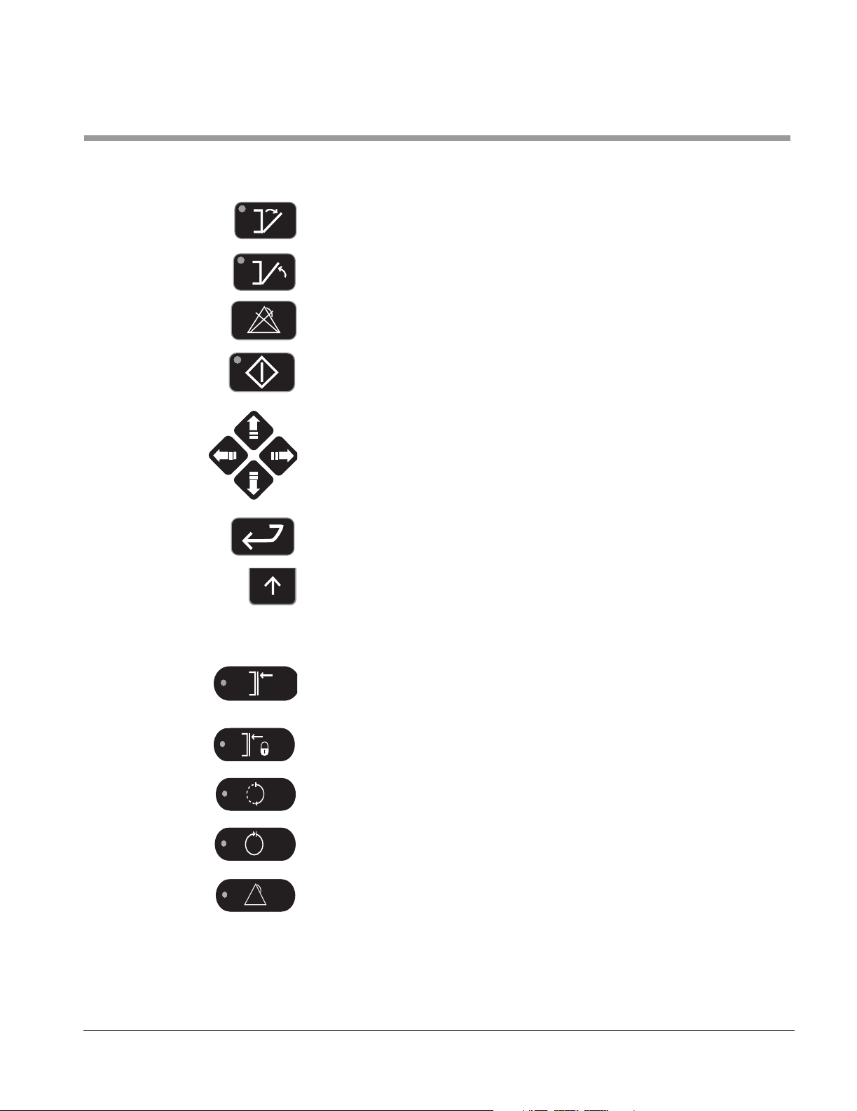
Open Door
Close Door
Clear Alarm
!
Start
Directional Arrows (for navigating display screens)
400LS/500LS Series Steam Sterilizers
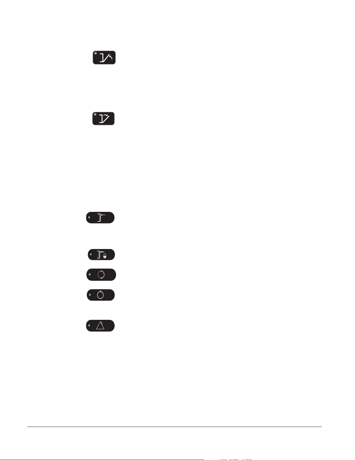
Indicators
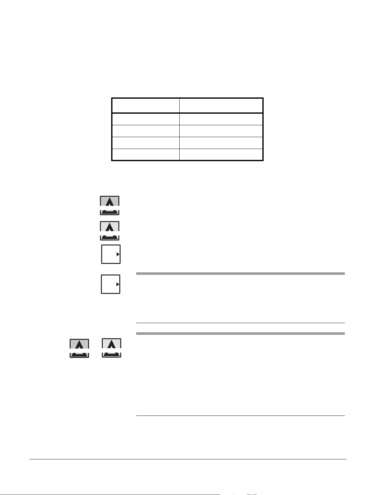
Enter
Up Arrows (for selecting softkey options (i.e. Save, Cancel, OK, and so
forth)
Door(s) Closed
Door(s) Sealed
In Process
Process Complete
Process Failure
!
61301608206 xv
Labels The following labels on the sterilizer alerts personnel to possible hazards.
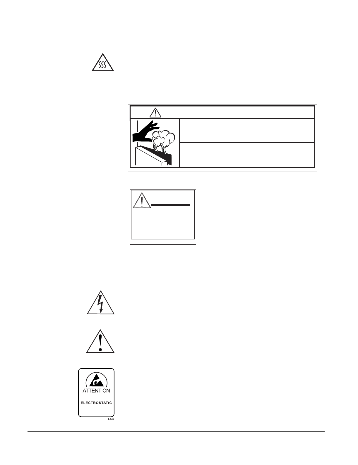
BURN HAZARD: Hot surfaces or heat-emitting area. Avoid contact. Risk of
burns.
HS
Burn Hazard
WARNING — BURN HAZARD
Steam released from the sterilizer chamber can
cause serious burns
Stand away while opening the door
If water leaks from the front of the sterilizer,
DO NOT open the door (
Contact Getinge USA Customer Support (800)950-9912
MGA
Load Processing Warning
WARNING
Processing a type
of load other
than defined in
Operator's Manual
could be hazardous.
61301609118 Rev. A
WS-0011
see Operator Manual)
61301602908 REV A
The following labels on the Control Box and Power Box alert service
personnel to possible hazards.
HIGH VOLTAGE
CAUTION: To reduce the risk of electrical shock, do not remove cover. Refer
servicing to qualified service personnel.
ATTENTION: Refer to accompanying documents for further information.
Electrostatic Sensitive Devices
OBSERVE PRECAUTIONS
FOR HANDLING
SENSITIVE
DEVICES
xvi

MANUAL CONVENTIONS
400LS/500LS Series Steam Sterilizers
Before you begin using this manual, it is important to understand the
conventions used. These conventions are established for visual ease of use.
ITALIC CAPS Display text, such as the ENTER PASSWORD
prompt.
[ALL CAPS] Softkeys on the control panel, such as [MORE] or
[OK].
ALL CAPS Switches and indicators on the control panel, such
as ENTER.
> The > symbol leads you through nested menu
items and dialog box options to a final action. For
example: SYSTEM MENU>enter
password>CONFIGURATION>EDIT CYCLES.
Italic Upper/Lower Case Cross reference to another section, manual, or
guide; such as: see 400/500 Series Steam
Sterilizers Service Manual.
PARAMETER SETTINGS
ACCESS REQUIRED
Parameter Setting Access Required is an alert
that a password with appropriate access rights is
necessary to proceed.
61301608206 xvii

xviii
MODELS
Section 1 Getting Started
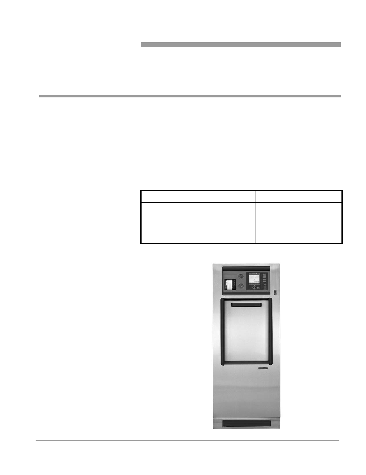
The 400LS/500LS Series Steam Sterilizers are designed to steam-sterilize
laboratory goods and solutions. Typical applications include:
•utensils
•glassware
• porous goods
• non-porous hard goods
• non-flammable/non-volatile liquids in self-venting or open containers
Models and cycle types are listed in Table 1–1.
Table 1–1. 400LS/500LS Series Steam Sterilizers
MODEL STERILIZER TYPE CYCLE TYPES AVAILABLE
422LS
522LS
433LS
533LS
Figure 1–1. 400LS/500LS SERIES STEAM STERILIZER
Gravity Gravity, Liquids
Vacuum Prevacuum, Gravity, Liquids,
Vacuum Leak Test
61301608206 1–1
Getting Started
S
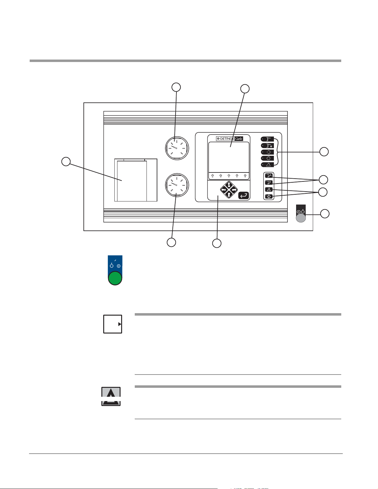
CONTROLS AND INDICATORS
Figure 1–2. STERILIZER FRONT PANEL
8
6
5
7
!
4
!
CONTROLS
ON / / OFF
2
1
WS-0047
CONTROLS
OFF ON
9
1. CONTROLS OFF/ON — This green push button turns the
3
sterilizer controls OFF and ON.
WS-0091
NOTES
WARNING
• Sterilizer controls are ON when the push button is pressed in
and illuminated.
• Sterilizer controls are OFF when the push button is released
and the button is not illuminated.
• If the CONTROLS OFF/ON button is illuminated and the backlit display is
blank, press any button (Up Arrow, Enter, and so forth) on the control
panel to turn ON the display back-light.
• If the CONTROLS OFF/ON button is pressed during a cycle, the cycle will
abort. This is not the recommended method to manually abort a cycle. To
manually abort a cycle, see "Canceling a Cycle (Manual Abort)" on page
5-2.
RISK OF CONTAMINATION: If the cycle is cancelled or
aborted, it must be considered incomplete and the load must
be repackaged and reprocessed.
1–2

400LS/500LS Series Steam Sterilizers
2. Cycle Switches:
• START — Begins the selected processing cycle.
• CLEAR/ALARM — Clears display messages and
!
silences any alarm. See "Display Messages" on
page 6-1.
3. Programming Switches:
• UP/DOWN/LEFT/RIGHT arrow keys—Used to:
1)select a cycle
(see "Previewing/Selecting a Cycle" on page 4-2).
2)enter a password
(see Enter a Password in the 400LS/500LS Series
Steam Sterilizers Supervisor Manual).
3)change adjustable cycle parameters
(see Edit Cycle Parameters in the 400LS/500LS
Series Steam Sterilizers Supervisor Manual).
4)navigate the menus
(see Menu Options in the 400LS/500LS Series
Steam Sterilizers Supervisor Manual).
• ENTER—Enables/stores selections in memory.
• UP ARROW softkeys—Usage varies depending on the
cycle and/or cycle phase. The softkey labels appear
above one of the five (5) arrow softkeys.
See Softkeys on page 2-6.
61301608206 1–3
Getting Started
4. DOOR CONTROL Switches:
•CLOSE DOOR
Manual Door units—Press the switch to seal the door;
however, the door seals automatically at the beginning
of the cycle.
Power Door units—Press the switch to close the door
or use the foot switch. Press the switch a second time
to seal the door.
• OPEN DOOR
Manual Door units—Press the switch to unseal the
door.
Power Door units—Press the switch to unseal the door.
Press the switch a second time to open the door or use
the foot switch.
Unidirectional Double Door units—unseals the unload
end (Remote End (RE)) door.
See "Opening and Closing the Sterilizer Door" on
page 4-15.
5. STATUS Indicators:
• DOOR(S) CLOSED—Indicates the door is closed, but
not sealed (or both doors are closed, but not sealed on
a double door unit).
• DOOR(S) SEALED—Indicates the door is sealed (or
both doors are sealed on a double door unit).
• IN PROCESS—Indicates a cycle is in progress.
• PROCESS COMPLETE—Green light indicates a cycle
is complete.
Flashing red light indicates an aborted cycle.
!
• PROCESS FAILURE—Flashing red light indicates that
the controls automatically aborted a cycle due to a
process failure, equipment malfunction, or failure while
in STANDBY.
1–4
400LS/500LS Series Steam Sterilizers
e
g
j
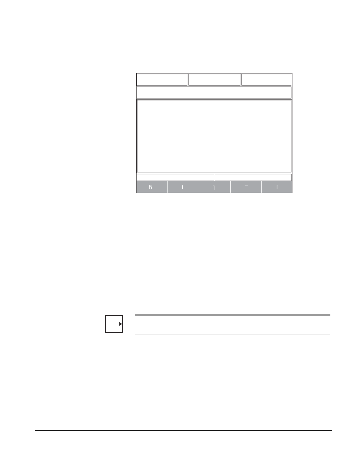
6. Display Window—The interface between the operator and
the sterilizer
Figure 1–3. DISPLAY WINDOW
a bc
d
NOTE
WS-0104
The Display Window includes:
a. Exposure Time
b. Exposure Temperature
c. Drying Time (not used for Liquid cycles)
d. Cycle information including:
• Cycle selected—Gravity, Liquids and Prevacuum.
• Phase name—Heat up, Exposure, Drying, Exhaust and Cycle
Complete to name a few.
• Time in the cycle—the cycle timer begins when the cycle
starts and continues to increase until the cycle is complete.
When the phase is STANDBY, the cycle timer does not increase.
• Time in current phase—the in-phase timer begins when each
phase starts and resets at the end of each phase.
• CYCLE COMPLETE—Green background
• PROCESS FAILURE—Flashing red background
61301608206 1–5

Getting Started
e. Process Screen includes:
• A user selectable process screen:
• Bar graph (See Figure 2–1 on page 2-2)
• Details (See Figure 2–2 on page 2-3)
• Plot graph (See Figure 2–3 on page 2-4)
•Dialog boxes
• Password window
NOTE
If all the items in the list do not fit on one screen, a black bar appears to the
right of the list. Use the UP/DOWN arrows to view any additional items.
f. Critical alarms
• Failure conditions
• Fault conditions
g. Non-critical information and system messages
• Informational messages
h. through l. — Five (5) softkey labels that display
different function names depending on the current
screen and/or cycle phase.
See "Softkeys" on page 2-6.
7. Printer — Provides a record of the cycle.
(see "Operating the Printer" on page 4-19).
8. Jacket Pressure Gauge — Indicates the current jacket
pressure.
9. Chamber Pressure Gauge — Indicates the current
chamber pressure.
1–6

COPY THESE 2 PAGES AND SAVE FOR REFERENCE
CYCLE ASSIGNMENTS
The sterilizer comes from the factory with up to 18 pre-assigned cycles as
shown in the 400LS/500LS Series Steam Sterilizers Supervisor Manual.
The cycle number and name can be changed by a qualified person with
configuration access privileges. When changes are made to the cycle
assignments write your setup in the form below.
Table 1–2. Cycle Assignments
400LS/500LS Series Steam Sterilizers
Cycle No. Cycle Type
Cycle Name
(8 Characters Max.)
Comments
61301608206 1–7

Getting Started
Table 1–2. Cycle Assignments
Cycle No. Cycle Type
Cycle Name
(8 Characters Max.)
Comments
Cycle type abbreviations:
• vac – Prevacuum(Models 433LS/533LS only)
• grv – Gravity
• liq – Liquids
• lkt – Vacuum Leak test (Models 433LS/533LS only)
DATE: ___________________
1–8

Section 2 Control Panel Navigation
The 400LS/500LS Series Steam Sterilizers have an easy to use interface.
This section covers:
• Three process screens—see page 2-2
• Softkey label assignments —see page 2-6
• Turning on the backlit display and the sterilizer controls—see page 2-7
• Basic navigation of the software—see page 2-8
For a description of the controls and indicators located on the control panel,
see Controls and Indicators page 1-2.
61301608206 2–1
Control Panel Navigation
E
C
P
C
A
PROCESS SCREENS
The user has the option of selecting one of three process screens:
• A screen with an enlarged timer (Bar Graph).
• A list of real-time process critical values, including, but not limited to,
chamber temperature, chamber pressure, jacket temperature,
atmosphere PSIA, chamber PSIA, Exposure temperature maximum,
exposure temperature minimum (Details).
• A screen with a graphical display (Plot Graph).
A password is not required to select a process screen.
Bar Graph Screen The Bar Graph screen displays the chamber temperature and pressure as a
bar graph and also shows a digital time representing the time remaining in
the cycle.
Figure 2–1. BAR GRAPH SCREEN
00:30:00
Exposure Time
P10 grv GRAVITY1
01 STANDBY
HAMBER TEM
37.3 C
SETUP
SELECT
CYCLE
121.1 C
Exposure Temp
0
REMAINING TIM
PARA -
METER
00:30:00
Drying Time
HAMBER PSI
14.68 PSI
Time in Cycle
00:00:00
00:24:15
Time in Current
Phase
Estimated Total
Time Remaining
in the Cycle
UNSEAL
WS-0014
2–2

400LS/500LS Series Steam Sterilizers
P
p
C
G
p
A
C
A
x
C
C
UNSEAL
S
CT
CYCLE
Details Screen The Details screen displays a list of real-time process critical values,
including: chamber temperature, chamber pressure, jacket temperature,
atmosphere PSIA, chamber PSIA, exposure temperature maximum,
exposure temperature minimum, steam table differential, overall
temperature time, machine counter, daily counter, leak test start, leak test
differential, and software version.
NOTE
If all the items in the list do not fit on one screen, a black bar appears to the
right of the list. Use the UP/DOWN arrows to view any additional items.
Figure 2–2. DETAILS SCREEN
00:30:00
Exposure Time
P10 grv GRAVITY 1
02 CYCL COMPLETE
Chamber Tem
hamb Press/PSI
Jacket Tem
Atmosphere PSI
hamber PSI
Exp. Temp Ma
Exp. Temp Min 121.4
SETU
ELE
121.1 C
Exposure Temp
61.2
0.00 PSI
122.3 C
14.37 PSI
14.35 PSI
121.7 C
00:30:00
Drying Time
01:36:36
00:04:34
WS-0012
61301608206 2–3

Control Panel Navigation
1
02 CYCL CO
E
UNSEAL
SETUP
01:36:36
00:03:42
p
C
A
8
35
e
0
0
C
C
SI
S
CT
CYCLE
E
C
P
C
A
The Plot Graph Screen The Plot Graph screen displays the chamber temperature and pressure as a
trend curve using a graphic display.
Figure 2–3. PLOT GRAPH SCREEN
00:30:00
Exposure Time
121.1 C
Exposure Temp
00:30:00
Drying Time
P10 grv GRAVITY
MPLET
14.
1.2
P
1:4
Tim
WS-0013 700H
ChamberTem
hamber PSI
ELE
Selecting a Process Screen The Bar Graph screen displays when the sterilizer control panel is turned
on. See Turning ON the Controls on page 2-7.
Figure 2–4. BAR GRAPH SCREEN
00:30:00
Exposure Time
P10 grv GRAVITY1
01 STANDBY
HAMBER TEM
37.3 C
SETUP
SELECT
CYCLE
121.1 C
Exposure Temp
REMAINING TIM
1. Press [SETUP].
The SETUP menu appears.
0
PARA -
METER
00:30:00
Drying Time
HAMBER PSI
14.68 PSI
00:00:00
00:24:15
UNSEAL
WS-0014
2–4

400LS/500LS Series Steam Sterilizers
2. Use the UP/DOWN ARROWS to select the process
screen:
• Bar Graph
• Details
• Plot Graph
3. Press ENTER.
The process screen selected appears.
61301608206 2–5

Control Panel Navigation
SOFTKEYS
Navigation of the software interface is controlled using the softkeys ( )
that appear at the bottom of each screen. The softkey labels, located
directly above the softkeys, change depending on the current main window
and/or the cycle phase. The following illustration shows the labels assigned
to each softkey.
NOTE
Access levels assigned determine the screens that are viewed.
Table 2–1. Softkey Assignments
Softkey Labels Screen or Procedure
SETUP SELECT
CYCLE
SETUP PARA-
SETUP PARA-
ABORT PHS
ADV
SETUP PARA-
CANCEL SETUP Menu
CANCEL OK SELECT CYCLE Screen
CANCEL MORE
CANCEL HOME OK EDIT PARAMETERS screen
CANCEL +/- CYCLE PARAMETER dialog box
CANCEL EDIT OK VIEW PARAMETERS screen
CANCEL CAPS
CANCEL DELETE OK ENTER PASSWORD screen
CANCEL HOME OK
CANCEL HOME System Menu Options
CANCEL HOME BRIGHT
PARA-
METER
METER
METER
METER
PARAMS
DELETE OK ADD USER, ACCESS AREAS or
LOCK
YES NO Confirmation message box
DEC
BRIGHT
INC
UNSEAL Startup or Default screen
UNSEAL Default Screen CYCLE COMPLETE
MORE Default Screen IN-CYCLE
EXIT Default Screen IN-CYCLE (Timed
Phase) (After MORE is pressed)
ABORT Default Screen IN-CYCLE (Untimed
Phase)
OK
or
SAVE
or
SAVE
OK ABOUT Screen
EDIT PARAMETERS screen
[MORE PARAMS]
MACHINE NAME screen
ALARM CLOCK, LANGUAGE DATE
UNITS, or PANEL SETUP screens
(If preference is enabled)
Softkeys
2–6

TURNING ON THE CONTROLS
To turn on the backlit display and the controls:
400LS/500LS Series Steam Sterilizers
CONTROLS
OFF ON
WS-0091
NOTES
Press the CONTROLS OFF/ON button.
• The switch illuminates and remains inward.
• The backlit display illuminates.
• The controls turn on.
• If the power is accidentally interrupted by pressing CONTROLS ON/OFF,
turn the controls back ON. The cycle is not cancelled if the controls are
turned ON within 2 seconds.
• If primary power is interrupted (e.g., a circuit breaker trips), the cycle is
not cancelled if power is restored within 59 seconds.
61301608206 2–7

Control Panel Navigation
NAVIGATION BASICS
Directional Arrows Each of the Directional Arrows has a specific function:
• Up Arrow ( ↑ )
• scrolls up a list on the process screen
• when the cursor is activated (blinking cursor), increases the
digit or value shown in reverse video
• Right Arrow (→)
• moves the cursor on the current screen or window right to
highlight a field
• Down Arrow ( ↓)
• scrolls down a list on the current screen or window.
• when the cursor is activated (blinking cursor), decreases the
digit or value shown in reverse video
• Left Arrow (←)
• moves the cursor on the current screen or window left to
highlight a field
ENTER Use the ENTER key to:
• Accept numbers and letters when entering passwords, machine names,
or changing a parameter setting.
• Select an item from a list (such as: a cycle from the list of available
cycles, a menu option, or a parameter).
Select an Item from a List Selecting an item from a list is very simple; the UP/DOWN arrow keys are
used to select the item and the ENTER key stores the selection in memory.
For more detailed instructions, see Previewing/Selecting a Cycle
on page 4-2.
2–8

400LS/500LS Series Steam Sterilizers
J
\
CE
/
Enter an Alphanumeric Value
When an alphanumeric value needs to be entered, a screen similar to
Figure 2–5 displays.
Figure 2–5. KEYBOARD SCREEN
00:30:00
Exposure Time
P10 grv GRAVITY1
01 STANDBY
ENTER PASSWORD
PASSWORD:
CANCEL
121.1 C
Exposure Temp
PA
DELETE
00:30:00
Drying Time
00:00:00
00:24:15
OK
WS-0017
When the keyboard screen appears, the blinking cursor is positioned at the
location of the first character of the string and the first key on the keyboard is
highlighted. The UP/DOWN/LEFT/RIGHT arrows are used to navigate to
the appropriate character; ENTER is used to select the character. The
selected character or # sign appears in the position of the blinking cursor
and the blinking cursor moves to the right of the character. Press [OK] when
the password is entered.
Softkeys:
• [CANCEL]—returns to the previous screen without accepting the
alphanumeric value.
• [DELETE]—deletes the character to the left of the cursor.
• [OK]—accepts the alphanumeric value and, in the case of the password
displays the next screen if a valid password is entered.
For more detailed instructions, see:
• Enter a Password in the 400LS/500LS Series Steam Sterilizers
Supervisor Manual.
• Set Up an Operator Password in the 400LS/500LS Series Steam
Sterilizers Supervisor Manual.
• Change an Operator Password in the 400LS/500LS Series Steam
Sterilizers Supervisor Manual.
• Edit the Cycle Number and Name in the 400LS/500LS Series Steam
Sterilizers Supervisor Manual.
• Assign the Sterilizer Name in the 400LS/500LS Series Steam Sterilizers
Supervisor Manual.
61301608206 2–9

Control Panel Navigation
E
P
A
c
Atomosphere PSIA
PSI
e
)
ss
Communicating With the System
Entering Data in Dialog Boxes
When a dialog box appears over the process screen, it is in read mode.
When ENTER is pressed, the screen goes into edit mode allowing
parameters to be selected and modified. Once in edit mode:
• LEFT/RIGHT arrows are used to select the parameter to be changed.
• UP/DOWN arrows are used to enter the new value.
• ENTER accepts the changes made and returns the screen to save mode.
• [SAVE] records the new values into memory and returns the screen to
read mode.
Figure 2–6. DATA VALUE ENTRY SCREEN
00:30:00
00:30:00
Exposure Time
P10 grv GRAVITY1
01 STANDBY
HAMBER TEM
Ja
Lo
Fo
37.3 C
121.1 C
Exposure Temp
Exposure Tim
00:01:00 - 06:00:00
:30:0 hh:mm:
00:30:00
Drying Time
HAMBER PSI
14.68 PSI
00:00:00
00:24:15
.03
0
Chamber PSIA 12.03 PSI
CANCEL
REMAINING TIM
ws-0212
For more detailed instructions, see Edit Cycle Parameters in the 400LS/
500LS Series Steam Sterilizers Supervisor Manual.
Responding to Yes/No Message Boxes
Yes/No message boxes appear over process screens and are used to
confirm changes made by the user (i.e., Confirm Save/Cancel). The user
responds to the message box by pressing either the [YES] or [NO] softkey at
the bottom of the process screen.
For more detailed instructions, see Setup the Display Panel in the 400LS/
500LS Series Steam Sterilizers Supervisor Manual.
2–10

400LS/500LS Series Steam Sterilizers
Exit from a Screen There are three commands used to exit from a screen:
• [CANCEL]—return to the previous screen without saving
changes
• [HOME]—return to the Main window and logs out the current
user.
• [OK]— return to the previous screen.
In the case of the Password Screen, pressing [OK] displays
the screen that corresponds to the function selected (when a
valid password is entered).
NOTES
• If both [OK] and [CANCEL] softkeys display:
a. Press [OK] to return to the previous screen.
b. When in edit mode (cursor blinking), press [CANCEL] to return to
the previous screen without saving any changes.
When not in edit mode, press [CANCEL] to return to the previous
screen
• If both [OK] and [CANCEL] (or [SAVE] and [CANCEL]) softkeys display,
the CONFIRM CANCEL? YES OR NO prompt appears when [CANCEL]
is pressed.
• The CONFIRM CANCEL? prompt can be turned off by changing the
CONFIRM SAVE/CANCEL setting on the PANEL SETUP Screen.
(See "Set up the Display Panel" in the 400LS/500LS Series Steam
Sterilizers Supervisor Manual)
61301608206 2–11

Control Panel Navigation
2–12

DAILY CHECKLIST
Section 3 Preparation for Use
HS
WARNING
NOTE
HOT SURFACES: The chamber and the gasket area could be
HOT. Turn OFF the controls and make sure the sterilizer is cool
before cleaning the gasket or removing the sediment screen for
cleaning.
Before operating the sterilizer each day:
1. Check the printer paper roll and replace it if necessary.
See Replacing the Printer Paper on page 4-21
2. Clean the sediment screens in the chamber drain.
See Cleaning the Sediment Screens on page 7-2
3. If the sterilizer is equipped with a steam boiler:
•allow the steam boiler to warm up for 20 to 30 minutes
before running a cycle.
•blow down the steam boiler as required.
See Manual Blow-Down on page 8-4
Some Getinge USA steam boilers are configured for automatic blow-down.
If your sterilizer has this feature, see "Automatic Blow-Down Package
(Option)" on page 8-7 for setup instructions for the automatic blow-down
option.
Operational Readiness To ensure that the sterilizer is ready for processing without requiring a
warm-up period:
• leave the sterilizer ON during regular periods of
sterilizer inactivity.
• close but do not seal the sterilizer door(s).
After daily operation, press CONTROLS OFF/ON to turn OFF the sterilizer
and allow the chamber time to cool down before cleaning the door gasket
and sediment screen.
61301608206 3–1

Preparation for Use
LOAD PREPARATION
WARNING
CAUTION
NOTE
• RISK OF CONTAMINATION: Airborne microbial and
particulate contamination is likely to be high in the
preparation area. Wear appropriate personal protective
equipment when preparing items for cleaning.
• RISK OF CONTAMINATION: If the cycle is cancelled or
aborted, it must be considered incomplete and the load must
be repackaged and reprocessed.
• POSSIBILITY OF INJURY: Only use vented or open
containers to process liquids in this sterilizer. Use of sealed,
unvented containers to process liquids can result in severe
personal injury due to container breakage. Getinge USA
does NOT recommend or endorse use of such containers.
POSSIBILITY OF EQUIPMENT DAMAGE: use of sealed unvented
containers to process liquids can result in permanent damage to
the sterilizer.
RIGID CONTAINER SYSTEM USERS: Contact the Rigid Container System
Manufacturer to determine validated cycle parameters and proper loading of
contents into the containers.
The 400LS/500LS Series Steam Sterilizers are designed to steam-sterilize
laboratory goods and solutions. Typical applications include:
•utensils
•glassware
• porous goods
• non-porous hard goods
• non-flammable/non-volatile liquids in self-venting or open containers
Clean, package, and load items according to established procedures for
your workplace.
3–2

400LS/500LS Series Steam Sterilizers
CREUTZFELDT-JAKOB DISEASE (CJD)
DECONTAMINATION
It is the responsibility of the laboratory facility to establish internal policies
and procedures relative to processing instruments that have or may have
been exposed to CJD. If instruments exposed to CJD are processed in
accordance with the World Health Organization (WHO) Infection Control
Guidelines for Transmissible Spongiform Encephalopathies (TSE), there
are:
POTENTIAL HAZARDS TO OPERATORS AND REPAIR PERSONNEL:
• Be sure to wear personal protective equipment (PPE) when
handling NaOH liquids.
• Heated NaOH liquids have the potential to injure personnel
who handle the containers.
• Heated NaOH liquids can emit fumes that can be corrosive to
eye tissue and can cause respiratory distress.
• Cleaning residual NaOH from the chamber interior could lead
to skin burns and the production of NaOH aerosol mist.
POTENTIAL DAMAGE TO THE STERILIZER:
• Processing caustic chemicals inside sterilizers is not
recommended.
• NaOH is corrosive to copper and brass and has the potential
to damage the chamber and lower piping.
Table 3–1. Load Chart
CYCLE TYPE TYPICAL LOAD
Gravity (grv)
Prevacuum (vac) Porous goods and hard goods
Liquids (liq)
Vacuum Leak Test (lkt) Empty chamber
• Hard goods, such as utensils and glassware
• Porous goods
• Goods that may be damaged if subjected to a
vacuum.
• Liquids in open or vented sealed containers
only
• Use flasks of Type 1 borosilicate (i.e. Pyrex
glass) only
61301608206 3–3

Preparation for Use
TECHNIQUES FOR LOADING
POSSIBILITY OF INJURY: Only use vented or open containers
WARNING
CAUTION
to process liquids in this sterilizer. Use of sealed, unvented
containers to process liquids can result in severe personal
injury due to container breakage. Getinge USA does NOT
recommend or endorse use of such containers.
POSSIBILITY OF EQUIPMENT DAMAGE: use of sealed unvented
containers to process liquids can result in permanent damage to
the sterilizer.
The following recommendations apply both to the loading car and transfer
carriage (see page 3-9) and to the rack and extendable shelves (see page
3-12):
• All packages must be positioned in the chamber to allow free circulation
and penetration of steam, enhance air elimination, and prevent
entrapment of air or water.
• Do not overload the loading car or shelves. When placing items on the
car or shelves, be sure there is enough space for free circulation of steam
around each pack and each item. This also ensures adequate air
elimination, steam penetration, and drainage of condensate, which are all
needed to attain product sterility.
• Items capable of holding water, such as basins and trays, should be
oriented in the same direction and arranged so that any condensate
drains out. Wicking material such as absorbent towels should be used to
absorb condensate.
• Large or heavy metal items should be placed on the lowest shelf to
enable the condensate to drain out without wetting other items in the
load.
• When using non-woven wrap, ensure there are no low spots that might
hold condensation.
• When processing liquids in open containers, fill the containers to only
75% of capacity (e.g., 750 mL for a 1 liter container). This will limit the
liquid loss to < 6% of the volume.
• Heat penetration of liquid solutions is affected by both liquid volume and
container geometry. To ensure effective sterilization processing, liquid
loads should be of a uniform volume and container size.
3–4

End of Cycle Routine
WARNINGS
NOTES
400LS/500LS Series Steam Sterilizers
• RISK OF CONTAMINATION: If the cycle is cancelled or
aborted, it must be considered incomplete and the load must
be reprocessed or repacked and reprocessed.
• RISK OF CONTAMINATION: Airborne microbial and
particulate contamination is likely to be high in the
preparation area. Wear appropriate personal protective
equipment when preparing items for cleaning.
• For detailed information regarding failure and fault conditions and
informational messages, refer to Diagnostic Message Types on page 6-2.
• For information regarding troubleshooting, refer to page 6-7.
The status of the completed load should be verified before removing the
load from the sterilizer. The following table outlines what to look for to
determine if a cycle completed successfully or aborted
61301608206 3–5

Preparation for Use
.
Table 3–2. Cycle Result Determination
Successful Cycle Aborted Cycle
• CYCLE COMPLETE is printed on the printout below the
• CYCLE ABORTED is printed on the printout.
CYCLE RESULTS.
SAMPLE PRINTOUT--COMPLETED CYCLE SAMPLE PRINTOUT--ABORTED CYCLE
SIGNATURE:................
PROCESS END
14:35:41
CYCLE RESULTS
Exp. Temp Max 121.8C
Exp. Temp Min 121.5C
Overall Time at Temp 00:32:34
DAILY COUNTER 2
01:36:36 14.37 102.9
CYCL COMPLETE
01:36:04 14.31 106.8
CE UNSEALING
01:36:04 14.31 106.9
CYCLE COMPLETE
• CYCLE COMPLETE appears against a green background* in the cycle information portion of the Display
window (Figure 1–3, Area d).
• PROCESS COMPLETE status indicator is green indicating a successfully completed cycle.
(NOTE: The message/phase clears/changes when the sterilizer door opens.)
• STANDBY appears against a flashing red background* in
• The failure message appears against a flashing red back-
• Pulsing alarm tone is activated.
• PROCESS COMPLETE status indicator is flashing red
• PROCESS FAILURE status indicator is flashing red.
• The sterilizer’s control system remains in STANDBY.
• The alarm silences when CLEAR ALARM is pressed.
• The message clears when the cause of the failure is cor-
SIGNATURE:................
CYCLE ABORTED
00:03:11 14.26 88.8
AIR-IN
00:03:00 14.24 89.1
00:02:10 14.22 100.3
DRYING
00:02:00 18.69 107.8
00:01:26 37.23 126.9
ABORT -HIGH TEMP
00:01.26 37.23 126.9
CYCLE ABORTED
the cycle information portion of the Display window. (Figure 1–3, Area d)
ground* in the critical alarms portion of the Display window. (Figure 1–3, Area f).
indicating an aborted cycle.
rected and CLEAR ALARM is pressed.
• The door automatically unseals, remains closed, and
ready to open.
(NOTE: Doors on unidirectional units do NOT automatically
unseal; check the cycle printout to confirm results.)
*panel version 3.07 or later
3–6
• The door remains sealed.
(NOTE: The door remains sealed until the failure condition is
acknowledged.)
POSSIBILITY OF INJURY: If a
WATER IN DRAIN message
WARNING
displays, DO NOT open the
chamber door manually. Hot water
in the chamber may spill out if the door is
opened. Wait until the message clears before
attempting to open the door.

Liquid RTD Placement (Option)
400LS/500LS Series Steam Sterilizers
WARNING
WARNINGS
BURN HAZARD: The liquid RTD may be HOT. Wear protective
gloves and glasses when placing the liquid RTD in the load or
removing it from the load.
Place the liquid RTD (load probe) into the center of the largest container
with the greatest volume of liquid and locate it in the coolest part of the
chamber (usually near the chamber drain). If the container is sealed, a selfventing automatic sealing stopper with an opening for the load probe is
required.
• POSSIBILITY OF INJURY: Only use vented or open
containers to process liquids in this sterilizer. Use of sealed,
unvented containers to process liquids can result in severe
personal injury due to container breakage. Getinge USA does
NOT recommend or endorse use of such containers.
• POSSIBILITY OF INJURY: Always keep the liquid RTD in the
storage holster (see Figure 3–1) when not in use. If the probe
is improperly stored, the controls may prematurely determine
that the cycle is complete. If the flasks are removed before
the cycle is complete, they may burst or crack.
POSSIBILITY OF EQUIPMENT DAMAGE: Use of sealed, unvented
CAUTION
Self-Venting
Automatic
Sealing Stopper
(bottom drain baffle
removed for clarity)
containers to process liquids can be result in permanent damage
to the sterilizer.
Figure 3–1. LIQUID RTD PLACEMENT
Drain
Storage Holster
Liquid RTD
(Load Probe)
WS-0226
61301608206 3–7

Preparation for Use
NOTE
For more information about the load probe, see Liquid RTD Package on
page 12-1.
3–8

LOADING ACCESSORIES
400LS/500LS Series Steam Sterilizers
CAUTION
Loading Car and Transfer Carriage (533LS only)
WARNING
Do not place items on the floor of the chamber. Always use the loading car
or shelf provided.
POSSIBILITY OF INJURY: The loading car can hold a
maximum load of 200 lbs. with a maximum of 100 lbs. evenly
distributed on each shelf. To avoid injury or equipment
damage, do not exceed these weight limits.
Figure 3–2. LOADING CAR AND TRANSFER CARRIAGE (533LS only)
Sterilizer
Chamber
Loading Car
(Door Open)
Track
Assembly
NOTES
Transfer
Carriage
Units equipped for racks and shelves
will not accept a loading car
and transfer carriage.
WS-0054
NOTE:
• Loading cars and transfer carriages are not available for 400LS Series
Steam Sterilizers.
• On power door units, be careful when aligning the transfer carriage with
the sterilizer chamber. Bumping the door control footswitch may
accidentally activate the door motor.
61301608206 3–9

Preparation for Use
To transfer the loading car to the chamber:
1. Align the car and carriage directly in front of the open
chamber. Make sure the carriage’s locking rod handle is in
the down position (see Figure 3–3).
2. Move the transfer carriage forward until the carriage
contacts the sterilizer door and the notches in the transfer
carriage align with the chamber rails.
3. Turn the locking rod handle approximately 90° to the “Lock
to Sterilizer” position.
4. Push the loading car onto the track assembly located in the
chamber.
5. Turn the locking rod handle back to the "Unlock and
Transport" position, then pull the carriage away from the
sterilizer.
Figure 3–3. TRANSFER CARRIAGE OPERATION
Sterilizer
Chamber
Notch
Carriage Locking
Plate
Chamber
Rail
Loading
Car
Lock to
Sterilizer
LOCKING ROD HANDLE DETAIL
Locking Rod
Handle
Unlock and
Transport
Transfer
Carriage
Transfer
Carriage
Loading Car Frame
Carriage
Lock
Loading Car Frame
WS-0095
3–10

400LS/500LS Series Steam Sterilizers
HS
WARNING
HOT SURFACES: The loading car may be hot enough to
cause burns. Wear protective gloves and eyewear when
loading and unloading the chamber.
To remove the loading car from the chamber:
1. Follow steps 1 through 3 on page 3-10 for positioning and
securing the transfer carriage in front of the open chamber.
2. Pull the loading car out of the chamber until the car’s axle
makes contact with the rod support rear block on the
carriage.
3. Turn the locking rod handle back to the “Unlock and
Transport” position.
4. Pull the carriage away from the sterilizer.
61301608206 3–11

Preparation for Use
Rack and Extendable Shelves The rack and extendable shelves are constructed of 300 series stainless
steel. The shelves are removable to facilitate cleaning.
The rack can hold up to four shelves. Two shelves are supplied; additional
shelves may be purchased as an option.
WARNINGS
HS
shelf-caution1
20 lbs.
MAX
DO NOT EXCEED 20 POUNDS
ON EXTENDED SHELVES
• HOT SURFACES: The rack and shelves may be hot enough
to cause burns. Wear protective gloves when loading and
unloading the chamber.
• POSSIBILITY OF INJURY: Observe the following loading
recommendations:
-The rack can support a maximum load of 100 lbs. An
individual shelf can hold up to 100 lbs., evenly distributed.
-Do not place more than 20 lbs. on the end of an extended
shelf.
-Liquid loads (hot or cold) should never be placed on an
extended shelf.
-Do not extend a shelf with liquid loads (hot or cold).
Figure 3–4. RACK AND EXTENDABLE SHELVES
Rack
(100 lb. Total Load
All Shelves)
Extendable
Shelves
DO NOT EXTEND SHELVES
CONTAINING BOTTLES
NOTE
• Routine cleaning (see page 7-4) prolongs the useful life of the shelves, as
chlorides from the steam or spillage from liquid loads may otherwise
corrode 300 series stainless steel.
• For information on positioning shelves and racks, see "Installing/
Removing, & Adjusting Shelf Racks" on page 7-15.
CAUTION
Do not place items on the floor of the chamber. Always use the loading car
or shelf.
3–12

SEQUENCE OF OPERATION
Section 4 Operating Instructions
This section covers the sequence a user may follow when sterilizing a load:
• Turning on the Controls—see page 4-2
• Previewing/Selecting a Cycle—see page 4-2.
• Loading the Sterilizer—see page 4-5.
• Editing Cycle Parameters—see page 4-6.
• Starting a Cycle—see page 4-7.
• Canceling a Cycle (Manual Abort)—see page 4-9.
• End of Cycle Routine—see page 4-10
• Unloading the Sterilizer—see page 4-12.
This section also covers:
• Opening and Closing the Sterilizer Door—see page 4-15.
• Operating the Printer—see page 4-19.
• Reading the Cycle Printout—see page 4-25.
• Performance Testing—see page 4-28.
61301608206 4–1

Operating Instructions
E
P
A
OPERATING THE STERILIZER
Turning on the Controls For information regarding controls, see Turning ON the Controls on page 2-
7.
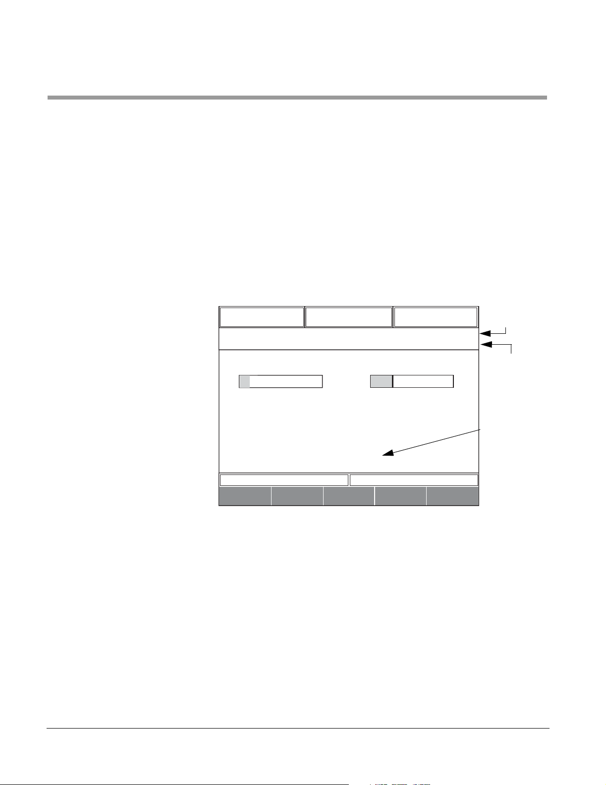
Previewing/Selecting a Cycle When making a cycle selection, pressing ENTER displays the exposure
time and temperature, drying time, and the cycle name for the selected
cycle at the top of the Main Display window (see Figure 4–1). This feature
permits preview of several different cycle settings before final selection.
After previewing the cycle, press OK to select the cycle.
NOTES
• The information that appears in the main display window depends on the
type of display chosen as the default (Details, Plot Graph, or Bar Graph).
• Press CANCEL at any time to return to the main display window without
selecting a cycle.
Figure 4–1. MAIN DISPLAY WINDOW (Bar Graph)
00:30:00
Exposure Time
P10 grv GRAVITY1
01 STANDBY
HAMBER TEM
37.3 C
121.1 C
Exposure Temp
00:30:00
Drying Time
HAMBER PSI
14.68 PSI
00:00:00
00:24:15
0
REMAINING TIM
SETUP
SELECT
CYCLE
PARA-
METER
UNSEAL
WS-0014-B
4–2

400LS/500LS Series Steam Sterilizers
E
P
A
E
P
A
To select a cycle:
1. From the main display window, press [SELECT CYCLE].
The SELECT CYCLE screen appears.
Figure 4–2. SELECT CYCLE SCREEN
00:30:00
Exposure Time
P10 grv GRAVITY1
01 STANDBY
SELECT CYCLE
P01
P02
P03
P04
P05
P06
P07
CANCEL
HAMBER TEM
vac PREVAC1
vac PREVAC1
37.3 C
vac PREVAC1
vac PREVAC1
vac PREVAC1
vac PREVAC1
grv GRAVITY1
121.1 C
Exposure Temp
0
REMAINING TIM
00:30:00
Drying Time
HAMBER PSI
14.68 PSI
ws-0156 400_500LS
00:00:00
00:24:15
OK
2. Use the UP/DOWN arrows to scroll the list of cycles.
The black bar at the right side of the screen indicates more
cycles exist than will fit on one (1) screen. Continued
scrolling refreshes the screen and displays any additional
cycles.
Stop scrolling when the desired cycle is highlighted.
Press ENTER to view
the parameters for the
highlighted cycle.
Use the UP/DOWN arrows
to highlight a cycle
Press CANCEL at any time
to return to the Main Display
screen without selecting a cycle.
3. Press ENTER to preview the cycle parameters.
The cycle name and cycle parameters appear at the top of
the display window.
Figure 4–3. SELECTING A CYCLE
00:30:00
Exposure Time
P10 grv GRAVITY1
01 STANDBY
SELECT CYCLE
P01
P02
P03
P04
P05
P06
P07
CANCEL
HAMBER TEM
vac PREVAC1
vac PREVAC1
37.3 C
vac PREVAC1
vac PREVAC1
vac PREVAC1
vac PREVAC1
grv GRAVITY1
121.1 C
Exposure Temp
0
REMAINING TIM
00:30:00
Drying Time
HAMBER PSI
14.68 PSI
00:00:00
00:24:15
OK
-
1
Press [OK}
to confirm the
selected cycle
61301608206 4–3

Operating Instructions
4. Verify the cycle parameters are correct for the load.
• If correct, press [OK] to confirm the cycle.
• If not correct, repeat steps 2 and 3 until the correct cycle
is selected.
NOTE
NOTE
Press CANCEL at any time to return to the main display window without
selecting a cycle.
The main display window displays.
If a cycle is highlighted without pressing [ENTER], pressing
[OK] will confirm the last cycle entered instead of the cycle
currently highlighted.
4–4

Loading the Sterilizer
WARNINGS
CAUTION
400LS/500LS Series Steam Sterilizers
• BURN HAZARD: The door and chamber area could be HOT
enough to cause burns. Wear personal protective equipment
(PPE) when loading the chamber.
• POSSIBILITY OF INJURY: Do not operate the door while
loading or unloading the sterilizer.
• POSSIBILITY OF INJURY: Wear protective eyewear, and
gloves when handling liquids in containers.
• POSSIBILITY OF INJURY: Only use vented or open
containers to process liquids in this sterilizer. Use of sealed,
unvented containers to process liquids can result in severe
personal injury due to container breakage. Getinge USA
does NOT recommend or endorse use of such containers.
POSSIBILITY OF EQUIPMENT DAMAGE: Use of sealed, unvented
containers to process liquids can be result in permanent damage to the
sterilizer.
NOTE
To load the sterilizer:
1. Open the door (if necessary). See Opening and Closing
the Sterilizer Door on page 4-15.
2. Place the load into the chamber.
See Loading Car and Transfer Carriage (533HC only) on
page 3-9 or Rack and Extendable Shelves on page 3-12.
Always place the load on a shelf or rack. Do not place the load on the floor
of the chamber.
3. Close the door. See Opening and Closing the Sterilizer
Door on page 4-15.
61301608206 4–5

Operating Instructions
Editing Cycle Parameters
• RISK OF CONTAMINATION: This sterilizer allows the user to
modify cycle settings, which may result in cycle parameters
that will not achieve the desired sterility assurance level
(SAL). Users with password access are responsible for
validation of any cycles that use other than the factory set
parameters.
• RISK OF CONTAMINATION: If the cycle is cancelled or
aborted, it must be considered incomplete and the load must
be repackaged and reprocessed.
After the load is placed within the sterilizer chamber, edit the cycle
parameters as necessary. A password is required to edit cycle parameters.
NOTE
For information regarding editing a cycle parameter, see Edit Cycle
Parameters in the 400LS/500LS Series Steam Sterilizers Supervisor
Manual.
4–6

Starting a Cycle
400LS/500LS Series Steam Sterilizers
WARNINGS
• Before pressing START, verify that the appropriate cycle is
selected for the load being processed.
• POSSIBILITY OF INJURY: If the wrong cycle is selected for a
liquid load, the containers may burst or crack during
processing.
• RISK OF CONTAMINATION: If the wrong cycle is selected,
the desired sterility assurance level (SAL) may not be
reached.
• RISK OF CONTAMINATION: If the cycle is cancelled or
aborted, it must be considered incomplete and the load must
be reprocessed (unwrapped goods or liquids) or repacked
and reprocessed (wrapped goods).
• RISK OF CONTAMINATION: If the Process Failure indicator
is flashing, the cycle must be considered incomplete and the
load must be repackaged and reprocessed.
• RISK OF CONTAMINATION: If the sterilizer canceled the
cycle due to a power interruption, the load must be
repackaged and reprocessed.
• POSSIBILITY OF INJURY: Only use vented or open
containers to process liquids in this sterilizer. Use of sealed,
unvented containers to process liquids can result in severe
personal injury due to container breakage. Getinge USA
does NOT recommend or endorse use of such containers.
POSSIBILITY OF EQUIPMENT DAMAGE: Use of sealed, unvented
CAUTION
NOTE
containers to process liquids can be result in permanent damage to the
sterilizer.
If the control panel shows UTILITY SHUTDOWN, see Bypassing Utility
Shutdown Mode on page B-53.
61301608206 4–7

Operating Instructions
To begin the sterilization cycle:
1. Press START.
a. The door(s) automatically seal (if not previously
sealed) and the DOOR(S) SEALED LED illuminates.
b. During the cycle, the IN PROCESS LED illuminates
and the chamber temperature and the elapsed time in
each phase display on the display screen.
c. At the end of the cycle, the PROCESS COMPLETE
LED illuminates and the buzzer sounds (the buzzer
silences automatically).
If the LED appears green, the cycle is complete.
If the LED appears flashing red, the cycle was aborted.
If a process failure occurs, the PROCESS FAILURE LED
!
flashes, an alarm sounds, the process stops, and a
diagnostic message appears on the printout.
NOTE
!
The failure message appears against a flashing red background* in the
critical alarms portion of the Display window. (Figure 1–3, Area f).
• Press CLEAR ALARM to clear the message (if the alarm
has corrected) and silence the alarm.
• Refer to Diagnostic Messages on page 6-8 for corrective
action.
4–8

Canceling a Cycle (Manual Abort)
400LS/500LS Series Steam Sterilizers
WARNING
NOTE
RISK OF CONTAMINATION: If the cycle is cancelled or
aborted, it must be considered incomplete and the load must
be repackaged and reprocessed.
A cycle can be cancelled during any phase. However, the softkeys at the
bottom of the display screen show different labels depending on the phase
of the cycle. If the cycle is in a timed phase (i.e. exposure), [MORE]
displays. If the cycle is in an untimed phase (i.e. heat-up), [ABORT]
displays.
See Canceling a Cycle (Manual Abort) on page 5-2.
If the CONTROLS OFF/ON button is pressed during a cycle, the cycle will
abort (after a 2 second timer expires). Therefore, this is not the
recommended method to manually abort a cycle. Use the [ABORT] softkey
instead
61301608206 4–9

Operating Instructions
End of Cycle Routine
WARNING
CAUTION
• RISK OF CONTAMINATION: If the cycle is cancelled or
aborted, it must be considered incomplete and the load must
be repackaged and reprocessed.
• RISK OF CONTAMINATION: If the Process Failure indicator
is flashing, the cycle must be considered incomplete and the
load must be repackaged and reprocessed.
• RISK OF CONTAMINATION: If the sterilizer canceled the
cycle due to a power interruption, the load must be
repackaged and reprocessed.
• POSSIBILITY OF INJURY: Only use vented or open
containers to process liquids in this sterilizer. Use of sealed,
unvented containers to process liquids can result in severe
personal injury due to container breakage. Getinge USA
does NOT recommend or endorse use of such containers.
POSSIBILITY OF EQUIPMENT DAMAGE: Use of sealed, unvented
containers to process liquids can be result in permanent damage to the
sterilizer.
NOTES
• For detailed information regarding failure and fault conditions, and
informational messages, refer to FAILURE CONDITION MESSAGES on
page 6-3.
• For information regarding troubleshooting and/or diagnostic messages
refer to Section 6, Tables 6–1 through 6–6.
The status of the completed load should be verified before removing the
load from the sterilizer. The following table outlines what to look for to
determine if a cycle completed successfully or aborted
4–10

.
Table 4–1. Cycle Result Determination
Successful Cycle Aborted Cycle
400LS/500LS Series Steam Sterilizers
• CYCLE COMPLETE is printed on the printout below the
• CYCLE ABORTED is printed on the printout.
CYCLE RESULTS.
SAMPLE PRINTOUT--COMPLETED CYCLE SAMPLE PRINTOUT--ABORTED CYCLE
SIGNATURE:................
PROCESS END
14:35:41
CYCLE RESULTS
Exp. Temp Max 121.8C
Exp. Temp Min 121.5C
Overall Time at Temp 00:32:34
DAILY COUNTER 2
01:36:36 14.37 102.9
CYCL COMPLETE
01:36:04 14.31 106.8
CE UNSEALING
01:36:04 14.31 106.9
CYCLE COMPLETE
• CYCLE COMPLETE appears against a green
background* in the cycle information portion of the
Display window (Figure 1–3, Area d).
• PROCESS COMPLETE status indicator is green
indicating a successfully completed cycle.
(NOTE: The message/phase clears/changes when the
sterilizer door opens.)
• STANDBY appears against a flashing red background* in
• The failure message appears against a flashing red
• Pulsing alarm tone is activated.
• PROCESS COMPLETE status indicator is flashing red
• PROCESS FAILURE status indicator is flashing red.
• The sterilizer’s control system remains in STANDBY.
• The alarm silences when CLEAR ALARM is pressed.
• The message clears when the cause of the failure is
SIGNATURE:................
CYCLE ABORTED
00:03:11 14.26 88.8
AIR-IN
00:03:00 14.24 89.1
00:02:10 14.22 100.3
DRYING
00:02:00 18.69 107.8
00:01:26 37.23 126.9
ABORT -HIGH TEMP
00:01.26 37.23 126.9
CYCLE ABORTED
the cycle information portion of the Display window.
(Figure 1–3, Area d)
background* in the critical alarms portion of the Display
window. (Figure 1–3, Area f).
indicating an aborted cycle.
corrected and CLEAR ALARM is pressed.
• The door automatically unseals, remains closed, and
• The door remains sealed.
ready to open.
(NOTE: The door remains sealed until the failure condition is
(NOTE: Doors on unidirectional units do NOT automatically
acknowledged.)
unseal; check the cycle printout to confirm results.)
POSSIBILITY OF INJURY: If a
WATER IN DRAIN message
WARNING
displays, DO NOT open the
chamber door manually. Hot water
in the chamber may spill out if the door is
opened. Wait until the message clears before
attempting to open the door.
*panel version 3.07 or later
.
61301608206 4–11

Operating Instructions
S
Unloading the Sterilizer
WARNING
HS
• RISK OF CONTAMINATION: After removing wrapped goods
from the chamber, inspect for residual moisture (wet packs).
Moisture on or within a package can potentially create a
pathway for migration of microorganisms from the outside to
the inside of a sterilized package.
• RISK OF CONTAMINATION: If the cycle is cancelled or
aborted, it must be considered incomplete and the load must
be repackaged and reprocessed.
• RISK OF CONTAMINATION: If the Process Failure indicator
is flashing, the cycle must be considered incomplete and the
load must be repackaged and reprocessed.
• RISK OF CONTAMINATION: If the sterilizer canceled the
cycle due to a power interruption, the load must be
repackaged and reprocessed.
• BURN HAZARD: The door and chamber area could be HOT
enough to cause burns. Wear personal protective equipment
(PPE) when loading and unloading the chamber.
• BURN HAZARD: Before removing a load from the chamber,
manually lower the door approximately one inch to allow
residual steam to escape. (If the sterilizer has a power door,
unseal the door and wait about a minute for the steam to vent
before opening the door.) Stand back to avoid possible burns
when lowering the door.
• HOT SURFACES: The loading car or rack and shelves may
be hot enough to cause burns. Wear protective gloves and
eyewear when removing the load from the chamber.
• POSSIBILITY OF INJURY: Wear protective eyewear,
clothing, and gloves when handling liquids in containers.
• POSSIBILITY OF INJURY: After completion of a liquids
cycle, carefully remove the container taking care not to
agitate the liquid. If the load is agitated when removed from
the chamber, the container may burst or crack.
• POSSIBILITY OF INJURY: Do not operate the door while
loading or unloading the sterilizer.
POSSIBILITY OF INJURY: Only use vented or open containers
WARNING
to process liquids in this sterilizer. Use of sealed, unvented
containers to process liquids can result in severe personal
4–12

CAUTION
400LS/500LS Series Steam Sterilizers
injury due to container breakage. Getinge USA does NOT
recommend or endorse use of such containers.
POSSIBILITY OF EQUIPMENT DAMAGE: Use of sealed, unvented
containers to process liquids can be result in permanent damage to the
sterilizer.
NOTE
NOTE
Before removing the load, be sure to check that the cycle was successful. as
indicated by the green PROCESS COMPLETE indicator. If the PROCESS
COMPLETE indicator is flashing red (failure), check the printer tape for
messages that indicate the cycle was aborted. Refer to "End of Cycle
Routine" on page 4-10.
Unload the sterilizer:
1. Unseal the door.
• Single door and standard double door units: The door(s)
automatically unseal at the end of the cycle.
• Interlocking double door units: The door at the unload
end automatically unseals at the end of the cycle.
• Unidirectional double door units: The door at the unload
end must be manually unsealed at the end of the cycle.
Wait for approximately one (1) minute for the steam to vent before opening
the door.
2. Open the door.
See Opening and Closing the Sterilizer Door on
page 4-15.
3. Remove the load
See Loading Car and Transfer Carriage (533LS only) on
page 3-9 or Rack and Extendable Shelves on
page 3-12.
4. Close the door.
• On unidirectional double door units, press SEAL DOOR
to seal the door at the unload end prior to unsealing the
door at the load end for the next cycle.
61301608206 4–13

Operating Instructions
• On interlocking double door units, press SEAL DOOR to
seal the door at the unload end and automatically unseal
the door at the load end for the next cycle.
4–14

OPENING AND CLOSING THE STERILIZER DOOR
S
• RISK OF CONTAMINATION: If the cycle is cancelled or
WARNING
HS
aborted, it must be considered incomplete and the load must
be repackaged and reprocessed.
• RISK OF CONTAMINATION: If the Process Failure indicator
is flashing, the cycle must be considered incomplete and the
load must be repackaged and reprocessed.
• RISK OF CONTAMINATION: If the sterilizer canceled the
cycle due to a power interruption, the load must be
repackaged and reprocessed.
• BURN/PINCH HAZARD: KEEP HANDS AND FINGERS
AWAY FROM A MOVING DOOR.
If your hands or fingers are accidentally caught in the door:
•Manual Door—gently reverse direction to open the door.
•POWER DOOR—PRESS THE FOOTSWITCH, OR THE
DOOR CONTROL SWITCH TO REVERSE THE DOOR
DIRECTION—or, manually open the door.
400LS/500LS Series Steam Sterilizers
CAUTION
• BURN HAZARD: The door and chamber area could be HOT
enough to cause burns. Wear personal protective equipment
(PPE) when loading and unloading the chamber.
• BURN HAZARD: Before removing a load from the chamber,
manually lower the door approximately one inch to allow
residual steam to escape. (If the sterilizer has a power door,
unseal the door and wait about a minute for the steam to vent
before opening the door.) Stand back to avoid possible burns
when lowering the door.
• POSSIBILITY OF INJURY: Do not operate the door while
loading or unloading the sterilizer.
• POSSIBILITY OF INJURY: Only use vented or open
containers to process liquids in this sterilizer. Use of sealed,
unvented containers to process liquids can result in severe
personal injury due to container breakage. Getinge USA
does NOT recommend or endorse use of such containers.
POSSIBILITY OF EQUIPMENT DAMAGE: Use of sealed, unvented
containers to process liquids can be result in permanent damage to the
sterilizer.
61301608206 4–15

Operating Instructions
Safety Features These safety features apply to all units:
• The operator cannot unseal a door during a processing cycle.
• If a door is not fully closed, it cannot be sealed.
• If a door is not sealed, a cycle cannot be started.
• If there is pressure or vacuum in the chamber at the end of the cycle, the
door cannot be unsealed.
Manual Door The sterilizer is equipped with a counterbalanced vertical sliding door.
Gentle upward or downward pressure on the door’s handle raises or lowers
the door.
The door is sealed by applying steam pressure behind the door gasket
located in the chamber headring. When pressure is applied, the gasket is
forced against the inside of the door, creating a door-to-chamber seal.
On single door units, a closed door seals automatically when START is
pressed. The door unseals automatically at the end of the cycle.
On standard double door units, both closed doors seal automatically when
START is pressed. The doors cannot be sealed individually.
NOTE
NOTE
On units with the interlocking double door option, both closed doors seal
automatically when START is pressed. The doors can be sealed
individually; however, when either door is sealed, the other door unseals
automatically. Only the door at the unload end unseals automatically at the
end of the cycle.
On unidirectional double door units, the door at the unload end must be
unsealed manually.
Be sure the doors are unsealed (Door(s) Sealed indicator OFF) before
turning OFF power to the controls or the sterilizer.
See Section 11 for information regarding unidirectional double door
operation.
To open the door:
1. Verify the Status of the Load. See "End of Cycle Routine"
on page 4-10.
2. If the DOOR(S) SEALED indicator is illuminated, press
OPEN DOOR to unseal the door.
3. Wait approximately 30 seconds to allow any trapped steam
to leave the chamber.
4. Apply gentle downward pressure on the door handle.
4–16

400LS/500LS Series Steam Sterilizers
CAUTION
Do not use excessive force when operating the door. Damage to the door or
the door’s latching mechanism could result.
To close the door:
1. Apply gentle upward pressure on the handle. The door
latches when fully closed.
2. The door seals automatically when the cycle starts.
Figure 4–4. DOOR OPERATION
WARNING
BURN/PINCH HAZARD: KEEP HANDS AND FINGERS AWAY
FROM A MOVING DOOR.
If your hands or fingers are accidentally caught in the door:
POWER DOOR—PRESS THE FOOTSWITCH, OR THE
DOOR CONTROL SWITCH TO REVERSE THE DOOR
DIRECTION—or, manually open the door.
Manual Door—gently reverse direction to open the door.
61301608206 4–17

Operating Instructions
Power Door (Option)
WARNING
On power door units, a motor raises and lowers the door, but does not seal
the door. The door is sealed when START or DOOR(S) SEALED is pressed.
BURN/PINCH HAZARD: KEEP HANDS AND FINGERS AWAY
FROM A MOVING DOOR.
If your hands or fingers are accidentally caught in the door:
POWER DOOR—PRESS THE FOOTSWITCH, OR THE
DOOR CONTROL SWITCH TO REVERSE THE DOOR
DIRECTION—or, manually open the door.
NOTES
NOTES
• A power door can also be raised and lowered manually.
• Wait for approximately one (1) minute for the steam to vent before
opening the door.
To open or close the door:
Press and release the footswitch at the bottom of the
sterilizer.
• It is not necessary to hold the footswitch while the motor is running; once
started, the motor runs until the door is fully open or closed.
• If there is an obstruction in the way of a moving door, the door stops after
several seconds. Press and release the footswitch to reverse the door
direction. Once the door is reversed and stops moving, remove the
obstruction.
To stop a moving door:
Press and release the footswitch. The door moves in the
reverse direction.
Figure 4–5. POWER DOOR SWITCH
4–18
Footswitch
WS-0045

OPERATING THE PRINTER
400LS/500LS Series Steam Sterilizers
At the beginning of the cycle, the printer records the date and time the cycle
was started, sterilizer name and ID number, cycle count, and cycle
parameter settings.
During the cycle, the printer records the chamber temperature and chamber
pressure at each transition point (start of a new phase), as well as the time
of the transition. During exposure, the temperature and pressure are printed
twice per minute.For liquids cycle that use the liquid RTD, the F
load temperature are also printed out. The program time is reset at the start
of each cycle.
value and
0
NOTES
NOTES
• The slow print interval (the time between data recordings) is factory set at
1 minute. The fast print interval (the time between recordings during
exposure) is factory set at 30 seconds. The print intervals can be
shortened (to record more data) or lengthened (to conserve paper) by a
qualified Getinge USA service representative.
• The temperature and pressure units (°C or °F; PSI, kPa, or bar) can be
configured by an operator with Configuration password access. See
"Select the Language, Date Format, and Units in the 400LS/500LS Series
Steam Sterilizers Supervisor Manual.
• The column layout of the printout can be configured by a qualified
Getinge USA service representative.
The printer also records any diagnostic messages that occur during the
cycle.
• Occasionally with the introduction of AC power to the sterilizer, the
message "LOW POWER BROWN OUT" may occur on the printout. This
message should be disregarded.
• When removing the load from the sterilizer at the end of the cycle, be sure
the printer’s plastic cover is closed. This prevents residual steam from
condensing on the printout or inside the cover.
• If the printer’s plastic cover is open and residual steam condenses on the
printout, it causes darkening of the thermosensitive paper.
The printer has a paper take-up core which holds a complete roll of paper. If
printouts of separate loads are required, this core can be removed. The
printout remains behind the paper cover until the operator opens the cover
and tears off the printout.
61301608206 4–19

Operating Instructions
Figure 4–6. PRINTER
CLEAR
COVER
COVER SLOT
ROLL
COVER
LEVER
RETAINER
CORE
SLOT
NOTCH
STATUS
TAB
STATUS
COPY
FEED
SHAFT
00-01A
STATUS Indicator The STATUS indicator on the printer blinks when the printer is out of paper
or there is a paper jam.
Figure 4–7. STATUS INDICATOR
OFF = NO POWER
ON = READY
BLINKING = PRINTER NOT READY,
PAPER NOT PROPERLY INSERTED,
OR ROLL COVER OPEN
A00866BC
Advancing the Paper To advance the paper through the printer, press and hold
FEED.
To stop the paper advance, release FEED.
To take up slack paper without advancing more paper:
1. Press and release FEED. Then immediately press and hold
FEED.
The core takes up slack paper.
2. Release FEED.
4–20

400LS/500LS Series Steam Sterilizers
Using the Lever The lever helps remove the core. (See Figure 4–8) To
remove a full core, press the lever in the direction of the
arrow. This opens the retainer.
Saving Printouts There are three ways to save printouts.
STATUS
• Full roll—to collect a complete roll on the core:
Insert the paper into the slot on the core, and remove the
core when it is full
00-01f
STATUS
(see Replacing the Printer Paper below).
• Small sections—to collect printouts of shorter periods,
such as daily use:
When loading paper, do not insert a new core. Instead,
00-01H
STATUS
feed the paper to the area by the shaft. When information is
printed, open the clear cover and tear off the printout.
• Separate printouts—to collect individual printouts
for each cycle:
For separate small printouts, feed the paper out through
the cover slot. During use, keep the clear cover closed.
00-01G
Before opening the sterilizer door, tear off the printout after
each cycle.
Tearing Off Printer Paper To tear off the printout for individual cycle records:
1. Press FEED for approximately one second. This advances
the paper beyond the SIGNATURE line of the printout.
2. Open the printer cover.
3. Tear off the printout against the tear blade at the top of the
printer.
4. Close the printer cover.
Replacing the Printer Paper
To replace the printer paper roll, follow the steps on page 4-23 and see
Figure 4–8 on page 4-22. For small section or separate printouts, see
Saving Printouts above.
For information on ordering printer paper and cores, see Consumable Stock
on page A-1.
61301608206 4–21

Operating Instructions
Figure 4–8. REPLACING THE ROLL
REMOVE THE USED CORE
STATUS
INSERT A NEW CORE
STATUS
ALIGN NOTCHES
WITH TABS
INSERT A NEW ROLL
LOAD THE PAPER
STATUS
STATUS
• PRESS AND RELEASE
• THEN PRESS AND HOLD
FOR 1 REVOLUTION
01-00-D
4–22

400LS/500LS Series Steam Sterilizers
Removing the Take-up Core The printer has a take-up core which holds a complete roll of paper. The
printout remains behind the clear cover until the cover is opened and the
printout is torn off or the paper roll removed.
1. Open the clear cover.
2. Press and hold the lever in the direction of the arrow.
3. Remove the core.
NOTE
If printouts of separate loads are required, the take-up core
can be removed.
Inserting a New Core 1. Still holding the lever, align the notches on the new core
with the tabs on the shaft. (See REPLACING THE ROLL,
Figure 4–8 on page 4-22.)
2. Release the lever. Seat the new core against the retainer.
Inserting a New Roll 1. Open the roll cover.
2. Remove the old roll.
3. Insert the new roll as shown.
4. Pull out about 6 inches of paper.
Be sure the plain side of the paper faces you.
Loading the Paper 1. Close the roll cover.
2. Fold the paper as shown (see Figure 4–9).
Figure 4–9. FOLD THE PAPER
FOLD
FOLD
00-01B
3. Rotate the new core so the slot faces you.
4. Insert the paper into the slot.
5. Press and release FEED. Then immediately press and hold
FEED.
• The core turns.
• Take up the paper at least one full revolution.
6. Release FEED. Close the clear cover.
61301608206 4–23

Operating Instructions
Storing and Handling Paper Rolls
NOTE
Printing a Duplicate Record
NOTE
The printer uses a special heat-sensitive paper. The printer does not print
on rolls of plain paper.
The paper should not be exposed to temperatures above 104°F (40°C) for
extended periods of time. Exposure to direct sunlight for several weeks or
longer may darken the paper, making the printout difficult to read.
Direct contact with steam discolors the paper, making the printout difficult to
read. Always close the clear protective cover after replacing the paper roll or
removing printouts from the take-up compartment.
To print a duplicate of the previous cycle record, press and
release COPY while the unit is not running a cycle.
The duplicate record prints.
• COPY only functions from the end of a cycle until the start of the next
cycle. Pressing CYCLE START clears the printer memory.
• During a cycle COPY is disabled.
4–24

READING THE CYCLE PRINTOUT
A sample cycle printout of a liquids cycle run on a 400LS/500LS Series
Steam Sterilizer has been provided in Figure 4–10. The proper
interpretation of the information produced during a cycle is provided below.
400LS/500LS Series Steam Sterilizers
NOTES
• When a printout of a cycle is produced, the cycle start is near the bottom
of the printout and the end of the cycle is near the top. When reading the
printout, always read from bottom to top.
• The sample printout shown in Figure 4–10 is from a liquids cycle. Different
sterilization cycles will produce printouts with slightly different information,
but time stamps and pressure and temperature readings are all read in
the same way.
• There are two (2) printer rates (fast log and slow log). The factory set
parameters are:
Fast Log — prints every 30 seconds during the exposure phase.
Slow Log — prints every 60 seconds during phases other than exposure.
Slow and Fast Log intervals may be adjusted by a qualified Getinge USA
Service Representative.
Cycle Start and Parameters Callout #1 shows a line of text which indicates that a new cycle has started
(e.g., DATE: 01/07/02).
The information between Callout #1 and Callout #3 lists some of the
parameters for the cycle. As an example, Callout #2 shows the EXPOSURE
TIME for the current cycle (00:30:00). The EXPOSURE TIME is the amount
of time the EXPOSURE TEMP shall be maintained.
Callout #3 shows the name of the current cycle. In this example, the cycle is
a liquids cycle named P13 liq LIQUIDS1.
Phases Each time a phase within a cycle starts, the phase name is recorded on the
printout. In the sample printout, Callout #4 shows the beginning of the LIQ
(liquid) EXPOSURE phase.
Immediately above the word LIQ EXPOSURE, the time the phase started
along with the chamber pressure and temperature are printed. In this
example, the printout shows the LIQ EXPOSURE phase started at
00:28:13, and, at that time, the chamber pressure was 30.57 PSIG and the
chamber temperature was 121.2°C.
During timed phases, the printer reports the appropriate cycle information
including F
temperature readings at regular intervals. LIQ EXPOSURE uses the fast log
rate, factory set at 30 seconds. Therefore, after the start of LIQ EXPOSURE
at 00:28:13, there are readings at 00:28:43, 00:29:13, and so forth. The
sample printout is truncated to fit on the page; normally, there are pressure/
temperature readings every 30 seconds for the entire 30 minute phase.
value, load temperature, along with chamber pressure and
0
61301608206 4–25

Operating Instructions
When the cycle transitions from one phase to the next, the new phase name
is printed along with the time the phase begins, F
as well as the chamber pressure and temperature readings. In this example,
Callout #5 shows the LIQ EXHAUST phase of the P13 liq LIQUIDS1 cycle
starting at 00:58:13. The beginning of the new phase (LIQ EXHAUST) also
marks the end of the previous phase (LIQ EXPOSURE).
value, load temperature,
0
Validating the Exposure Phase
NOTES
• Phases do NOT overlap.
• Different cycles will feature different phases and parameters.
Unlike the LIQ EXPOSURE phase where readings are printed at the fast log
rate, the LIQ EXHAUST phase readings are reported at the slow log rate.
The following paragraphs use the cycle parameters and results to validate
the EXPOSURE phase.
The start time of each phase within a cycle is printed. Therefore, it is
possible to determine the total time of any given phase. In Figure 4–10,
Callout #6 shows the LIQ EXPOSURE phase starting at 00:28:13 and the
LIQ EXHAUST phase starting at 00:58:13, the total exposure time is the
difference between the two start times, or 00:30:00. This can be validated by
the EXPOSURE TIME parameter in Callout #2 which reads 00:30:00.
Examining the EXPOSURE TEMP parameter appearing above EXPOSURE
TIME (Callout #2), reveals the P13 liq LIQUIDS1 cycle requires an exposure
temperature of 121.1°C. During the LIQ EXPOSURE phase the
temperatures recorded are between 121.2 and 121.9°C which are within
acceptable sterilization variances.
This information shows the LIQ EXPOSURE phase is valid because
121.1°C was achieved and maintained for a time of at least 00:30:00.
CYCLE END
Callout #7 shows a line that reads CYCLE COMPLETE followed by a line
with a time stamp, pressure and temperature reading. This is the end of the
P13 liq LIQUIDS1 cycle.
CYCLE RESULTS
Pertinent information regarding the cycle is displayed together for ease of
use. The information includes:
• The number of cycles completed; this counter resets everyday at
midnight. (DAILY COUNTER)
• The amount of time the sterilizer was at exposure temperature.
(OVERALL TMP TIME)
• The minimum (EXP TEMP MIN) and maximum (EXP TEMP MAX)
exposure temperature which occurred during the cycle.
4–26

Figure 4–10. SAMPLE PRINTOUT (Liquids Cycle with Load Probe)
7. Time stamp at end of cycle.
6. Total exposure time
00:58:13 (liq. exposure end)
- 00:28:13 (liq. exposure start)
00:30:00 *Total exposure time
400LS/500LS Series Steam Sterilizers
Top of Printout/End of Cycle
SIGNATURE: . . . . . . . . . . . . . . . . . . . . . . . . . . . . . . . . . ..
PROCESS END
02:30:00
CYCLE RESULTS
Exp. Temp Max 122.3C
Exp. Temp Min 121.6C
Overall Tmp Time 00:42:10
DAILY COUNTER 110
02:15:36 48.9 98.0 14.38 82.6
CYCL COMPLETE
02:15:06 48.9 98.0 14.39 87.1
CE UNSEALING
02:15:05 48.9 98.1 14.39 87.1
AIR-IN
02:15:00 48.9 98.1 14.35 87.1
02:14:00 48.9 98.1 14.37 87.2
5. Time stamp
for end of Liquid Exposure cycle
and beginning of Liquid Exhaust.
4. Beginning of Liquid Exposure cycle.
3. Cycle name.
2. Set exposure time.
1. Date stamp - denotes start of cycle.
Read tape from bottom to top.
00:59:00 40.8 121.7 30.03 121.4
00:58:13 39.9 121.8 30.43 121.8
LIQ EXHAUST
00:58:00 39.7 121.9 30.37 121.8
00:57:30 39.1 121.8 30.50 121.9
00:57:00 38.5 121.8 30.45 121.8
00:28:13 5.3 121.2 30.57 122.1
LIQ EXPOSURE
00:28:00 5.1 121.1 30.84 122.3
00:27:00 4.1 120.6 30.77 122.2
00:02:01 0.0 28.6 14.95 79.8
LIQ HEAT-UP
00:02:00 0.0 28.5 14.95 79.1
00:00:00 0.0 26.0 14.46 59.0
PURGE
00:00:00 0.0 26.0 14.45 59.0
START
PROGTIME F000 A102 A103 A100
PROGRAM: P13 liq LIQUIDS1
A100 CHAMBER TEMP
A103 CHAMB PSIA
A102 Load Temp
F000 Fo Value
SIGNALS
BlowDown Durat. 00:00:00
Chamber Cooldown 0.75 /M
Fo Value Reached 0.0
Exposure Time 00:30:00
Liq Dwell Time 00:00:00
Exp Overdrive 1.0 C
Exposure Temp 121.1 C
Purge Time
PARAMETERS
CYCLE COUNTER : 236
MACHINE NAME : 544LS
PROCESS START : 11:38:12
DATE : 11/12/04
00:02:00
Bottom of Printout/Start of Cycle
WS-0223
61301608206 4–27

Operating Instructions
PERFORMANCE TESTING
Biological Monitoring Biological monitoring is used to document the efficacy of specific steam
sterilization cycle.
• Biological indicator test pack should be used during initial installation of
steam sterilizers.
• Biological indicator test pack should be used in steam sterilization loads
weekly, preferably daily.
• Each load containing implantable devices must be monitored. Whenever
possible, the implantable devices should be quarantined until the results
of the biological testing are available.
The Getinge USA Biosign Biological Indicators are self-contained test units
for monitoring steam sterilization cycles. Biosign is available as an individual
test (Part No. 61301600022) or as a pre-assembled single-use test pack
(Part No. 61301603337).
4–28

400LS/500LS Series Steam Sterilizers
Vacuum Leak Test To run a vacuum leak test cycle:
1. Make sure the sterilizer chamber is empty.
2. Close the sterilizer door(s).
3. Select the Vacuum Leak Test cycle.
4. Press START.
a. The vacuum leak test cycle begins.
b. The cycle includes a conditioning phase, a 3 minute
exposure phase, a 15 minute drying phase, and a 5
minute dwell phase followed by a 15 minute leak test.
The test takes approximately 40 minutes.
c. During the cycle, LEAK TEST displays.
d. At the end of the cycle, the buzzer sounds and CYCLE
COMPLETE displays.
5. Check the results:
a. If the sterilizer passes the test (LEAK TEST FAIL does
not display), the sterilizer is functioning properly.
• Repeat the air removal test (Bowie-Dick test), carefully
following the instructions on the S.M.A.R.T. Pack.
• If the sterilizer fails the Bowie-Dick test a second time, consult
the B-D Test Pack manufacturer and/or a qualified
Getinge USA service representative.
b. If the sterilizer fails the test (LEAK TEST FAIL), shut
down the sterilizer and check the condition of the
gasket. If the gasket requires replacement, either
follow the procedure Replacing the Door Gasket(s) on
page 7-9 or call service. Do not process any loads in
the sterilizer until the problem is identified and
corrected.
61301608206 4–29

Operating Instructions
4–30

Section 5 Conditional Instructions
The following procedures provide information and instructions for situations
that may develop that are not part of standard sterilizer operation:
• Canceling a Cycle (Manual Abort) — see page 5-2.
• Advancing a Cycle (Manual Phase Advance) — see page 5-6.
• End of Cycle Routine— see page 5-9
• Shutting Down the Sterilizer — see page 5-11.
• Recovering from an Electrical Power Failure — see page 5-13.
• Opening the Door Manually — see page 5-15.
61301608206 5–1

Conditional Instructions
CANCELING A CYCLE (MANUAL ABORT)
WARNINGS
CAUTION
• RISK OF CONTAMINATION: If the cycle is cancelled or
aborted, it must be considered incomplete and the load must
be repackaged and reprocessed.
• RISK OF CONTAMINATION: Airborne microbial and
particulate contamination is likely to be high in the
preparation area. Wear appropriate personal protective
equipment (PPE) when preparing items for cleaning.
• BURN HAZARD: The door and chamber area could be HOT
enough to cause burns. Wear personal protective equipment
(PPE) when loading and unloading the chamber.
• POSSIBILITY OF INJURY: Only use vented or open
containers to process liquids in this sterilizer. Use of sealed,
unvented containers to process liquids can result in severe
personal injury due to container breakage. Getinge USA
does NOT recommend or endorse use of such containers.
POSSIBILITY OF EQUIPMENT DAMAGE: use of sealed unvented
containers to process liquids can result in permanent damage to
the sterilizer.
A cycle can be cancelled during any phase of operation. However, the
softkeys at the bottom of the display screen show different labels depending
on the phase of the cycle. If the cycle is in a timed phase (i.e. exposure),
[MORE] displays. If the cycle is in an untimed phase (i.e. heat-up), [ABORT]
displays.
5–2

400LS/500LS Series Steam Sterilizers
E
P
A
E
P
A
Timed Phase During a timed phase (i.e. exposure), the screen appears as follows:
Figure 5–1. IN-CYCLE SCREEN
NOTE
00:30:00
Exposure Time
P10 grv GRAVITY1
04 EXPOSURE
HAMBER TEM
121.3 C
121.1 C
Exposure Temp
00:30:00
Drying Time
HAMBER PSI
30.20 PSI
01:01:53
00:25:48
36
REMAINING TIM
SETUP
If the sterilizer is not in a timed phase (i.e. waiting for the chamber to heat
up), ABORT displays in the same position as MORE in the previous figure.
To cancel a cycle during a timed phase:
PAR A-
METER
MORE
WS-0096
1. Press [MORE].
The screen appears as follows:
Figure 5–2. IN-CYCLE SCREEN (ABORT)
00:30:00
Exposure Time
P10 grv GRAVITY1
04 EXPOSURE
HAMBER TEM
121.3 C
121.1 C
Exposure Temp
HAMBER PSI
30.20 PSI
36
REMAINING TIM
ABORT
PHS ADV
00:30:00
Drying Time
01:01:53
00:25:48
EXIT
ws-0157
61301608206 5–3

Conditional Instructions
E
P
A
2. Press [ABORT].
The sterilizer ceases all processing activity and begins an
exhaust (or liquid exhaust) phase (including exhaust, dry,
air in, and standby phases).
3. Wait for the appropriate exhaust phase to complete and
STANDBY is displayed.
4. Press OPEN DOOR to unseal the door(s).
Wait approximately one (1) minute for the steam to vent
before opening the door.
5. Open the door about an inch for 10 seconds to allow
residual steam vapors to escape.
On power door units, unseal the door and wait about a
minute for the steam to vent before opening the door.
NOTE
If the load was a liquid load, wait 15 minutes before removing the load from
the chamber.
6. Verify the status of the load. See End of Cycle Routine on
page 5-9.
7. Remove the load from the chamber.
Untimed Phase During an untimed phase (i.e. Heat-up), the screen appears as
follows:
Figure 5–3. IN-CYCLE SCREEN
00:30:00
Exposure Time
P10 grv GRAVITY1
02 HEAT-UP
HAMBER TEM
121.3 C
121.1 C
Exposure Temp
00:30:00
Drying Time
HAMBER PSI
30.20 PSI
00:30:14
00:24:15
66
REMAINING TIM
SETUP
NOTE
If the sterilizer is in a timed phase (i.e. exposure), MORE displays in the
same position as ABORT in the previous figure.
5–4
PARA-
METER
ABORT
ws-0111

400LS/500LS Series Steam Sterilizers
To cancel the cycle during an untimed phase:
1. Press [ABORT].
The sterilizer ceases all processing activity and begins an
exhaust (or liquid exhaust) phase.
2. Wait for the appropriate exhaust phase to complete and
STANDBY displays.
3. Press OPEN DOOR switch to unseal the door(s).
4. Open the door about an inch for 10 seconds to allow
residual steam vapors to escape.
On power door units, unseal the door and wait about a
minute for the steam to vent before opening the door.
NOTE
If the load was a liquid load, wait 15 minutes before removing the load from
the chamber.
5. Verify the status of the load. See End of Cycle Routine on
page 5-9.
6. Remove the load from the chamber.
61301608206 5–5

Conditional Instructions
ADVANCING A CYCLE
ARNINGS
This feature may be used to terminate a timed phase and advance to the
next phase. Timed phases include: PURGE, LIQ DWELL, EXPOSURE, LIQ
EXPOSURE, and DRYING.
• RISK OF CONTAMINATION: If the cycle advance feature is
used, the cycle must be considered incomplete and the load
must be repackaged and reprocessed.
• RISK OF: CONTAMINATION: If the cycle is cancelled or
aborted, it must be considered incomplete and the load must
be repackaged and reprocessed.
• RISK OF CONTAMINATION: Airborne microbial and
particulate contamination is likely to be high in the
preparation area. Wear appropriate personal protective
equipment (PPE) when preparing items for cleaning.
• BURN HAZARD: The door and chamber area could be HOT
enough to cause burns. Wear personal protective equipment
(PPE) when loading the chamber.
NOTE
• POSSIBILITY OF INJURY: Only use vented or open
containers to process liquids in this sterilizer. Use of sealed,
unvented containers to process liquids can result in severe
personal injury due to container breakage. Getinge USA
does NOT recommend or endorse use of such containers.
The cycle advance feature is intended for use by qualified service personnel
only. Improper use of this feature can compromise the integrity of the
processing cycle.
5–6
400LS/500LS Series Steam Sterilizers
E
P
A
E
P
A
To advance a cycle:
From the Main Display screen shown in the following figure:
Figure 5–4. MAIN DISPLAY SCREEN
00:30:00
Exposure Time
P10 grv GRAVITY1
04 EXPOSURE
HAMBER TEM
121.3 C
121.1 C
Exposure Temp
00:30:00
Drying Time
HAMBER PSI
30.20 PSI
01:01:53
00:25:48
36
REMAINING TIM
SETUP
1. Press [MORE].
The softkey labels at the bottom of the screen appear as
shown in the following figure.
Figure 5–5. MAIN DISPLAY SCREEN (ADVANCE CYCLE)
00:30:00
Exposure Time
P10 grv GRAVITY1
04 EXPOSURE
PAR A-
METER
121.1 C
Exposure Temp
00:30:00
Drying Time
01:01:53
00:25:48
MORE
WS-0096
HAMBER TEM
121.3 C
HAMBER PSI
30.20 PSI
36
REMAINING TIM
ABORT
61301608206 5–7
PHS ADV
EXIT
ws-0157

Conditional Instructions
2. Press [PHS ADV].
The CYCLE ADVANCED message displays for 5 seconds
and is printed on the paper tape.
After a cycle phase is advanced, the cycle continues
through the air-in phase but the controls enter STANDBY
mode, bypassing the CYCLE COMPLETE phase.
3. Verify the status of the load. See End of Cycle Routine on
page 5-9.
4. Remove the load from the chamber.
5–8

END OF CYCLE ROUTINE
400LS/500LS Series Steam Sterilizers
WARNING
CAUTION
• RISK OF CONTAMINATION: If the cycle is cancelled or
aborted, it must be considered incomplete and the load must
be repackaged and reprocessed.
• RISK OF CONTAMINATION: If the Process Failure indicator
is flashing, the cycle must be considered incomplete and the
load must be repackaged and reprocessed.
• RISK OF CONTAMINATION: If the sterilizer canceled the
cycle due to a power interruption, the load must be
repackaged and reprocessed.
• POSSIBILITY OF INJURY: Only use vented or open
containers to process liquids in this sterilizer. Use of sealed,
unvented containers to process liquids can result in severe
personal injury due to container breakage. Getinge USA
does NOT recommend or endorse use of such containers.
POSSIBILITY OF EQUIPMENT DAMAGE: use of sealed unvented
containers to process liquids can result in permanent damage to
the sterilizer.
NOTES
• For detailed information regarding failure and fault conditions, and
informational messages, refer to FAILURE CONDITION MESSAGES on
page 6-3.
• For information regarding troubleshooting and/or diagnostic messages
refer to Section 6, Tables 6–1 through 6–6.
The status of the completed load should be verified before removing the
load from the sterilizer. The following table outlines what to look for to
determine if a cycle completed successfully or aborted
61301608206 5–9

Conditional Instructions
.
Table 5–1. Cycle Result Determination
Successful Cycle Aborted Cycle
• CYCLE COMPLETE is printed on the printout below the
CYCLE RESULTS.
• CYCLE ABORTED is printed on the printout.
SAMPLE PRINTOUT--COMPLETED CYCLE SAMPLE PRINTOUT--ABORTED CYCLE
SIGNATURE:................
CYCLE ABORTED
00:03:11 14.26 88.8
AIR-IN
00:03:00 14.24 89.1
00:02:10 14.22 100.3
DRYING
00:02:00 18.69 107.8
00:01:26 37.23 126.9
ABORT -HIGH TEMP
• CYCLE COMPLETE appears against a green
background* in the cycle information portion of the
Display window (Figure 1–3, Area d).
• PROCESS COMPLETE status indicator is green
indicating a successfully completed cycle.
(NOTE: The message/phase clears/changes when the
sterilizer door opens.)
00:01.26 37.23 126.9
• STANDBY appears against a flashing red background* in
the cycle information portion of the Display window.
(Figure 1–3, Area d)
• The failure message appears against a flashing red
background* in the critical alarms portion of the Display
window. (Figure 1–3, Area f).
• Pulsing alarm tone is activated.
• PROCESS COMPLETE status indicator is flashing red
indicating an aborted cycle.
• PROCESS FAILURE status indicator is flashing red.
• The sterilizer’s control system remains in STANDBY.
• The alarm silences when CLEAR ALARM is pressed.
• The message clears when the cause of the failure is
corrected and CLEAR ALARM is pressed.
CYCLE ABORTED
• The door automatically unseals, remains closed, and
ready to open.
(NOTE: Doors on unidirectional units do NOT automatically
unseal; check the cycle printout to confirm results.)
*panel version 3.07 or later
5–10
• The door remains sealed.
(NOTE: The door remains sealed until the failure condition is
acknowledged.)
POSSIBILITY OF INJURY: If a
WATER IN DRAIN message
WARNING
displays, DO NOT open the
chamber door manually. Hot water
in the chamber may spill out if the door is
opened. Wait until the message clears before
attempting to open the door.

SHUTTING DOWN THE STERILIZER
In an emergency, it may be necessary to remove electrical power from the
sterilizer or to turn off the steam and water supplies. All operators should
know the location of the mains disconnect circuit breaker and the steam and
water supply shutoff valves at the sterilizer site.
400LS/500LS Series Steam Sterilizers
NOTE
The CONTROLS OFF/ON switch turns OFF the controls only; it does not
remove all power from the sterilizer.
Turning Off Electrical Power 1. Turn OFF power to the sterilizer at the mains disconnect
circuit breaker (see Figure 5–6 on page 5-12).
2. If the sterilizer has an uninterruptible power supply (UPS),
press the Off/Standby switch on the UPS (see Figure 10–1
on page 10-1).
3. If the sterilizer has a steam boiler or a vacuum pump, turn
off the three-phase voltage at the circuit breaker.
61301608206 5–11

Conditional Instructions
!
/
Turning Off the Steam and Water Supplies
Steam Supply
(units without steam generator)
Cold Water Supply
Cold Water
Shutoff
If the sterilizer does not have a steam boiler, turn off the steam and cold
water supplies.
Figure 5–6. CIRCUIT BREAKERS AND SHUTOFF VALVES
Hot Water Supply
(units with steam generator)
Steam
Shutoff
115 VAC
!
C
O
N
T
O
R
N
O
L
/
S
O
F
F
Hot Water
Shutoff
UPS
(option)
Three-Phase Voltage
to Vacuum Pump
Three-Phase Voltage
to Steam Boiler
Main
Disconnect
Circuit
Breaker
Circuit
Breaker
Vacuum Pump
- or -
(option)
Steam
Boiler
(option)
WS-0197
5–12

RECOVERING FROM ELECTRICAL POWER FAILURE
S
• RISK OF CONTAMINATION: If the sterilizer canceled the
WARNING
cycle due to a power interruption, the load must be
repackaged and reprocessed.
• RISK OF CONTAMINATION: If the cycle is cancelled or
aborted, it must be considered incomplete and the load must
be repackaged and reprocessed.
• RISK OF CONTAMINATION: If the Process Failure indicator
is flashing, the cycle must be considered incomplete and the
load must be repackaged and reprocessed.
• POSSIBILITY OF INJURY: Only use vented or open
containers to process liquids in this sterilizer. Use of sealed,
unvented containers to process liquids can result in severe
personal injury due to container breakage. Getinge USA
does NOT recommend or endorse use of such containers.
400LS/500LS Series Steam Sterilizers
CAUTION
NOTES
POSSIBILITY OF EQUIPMENT DAMAGE: use of sealed unvented
containers to process liquids can result in permanent damage to
the sterilizer.
When a power failure occurs, the controls store cycle information in shortterm, non-volatile memory. This information includes whether a cycle was in
progress, the current cycle type, the current cycle phase, and elapsed time
in the current phase.
• Cycle assignments and settings are backed up by a lithium battery inside
the control box. This battery is not user-replaceable but has a 10-year
shelf-life.
• If the sterilizer has an uninterruptible power supply, the UPS provides
power to the sterilizer controls. See Section 10 for information on the
UPS.
61301608206 5–13

Conditional Instructions
Power Failure During Standby
If a power failure occurs while in STANDBY, the sterilizer returns to
STANDBY mode, when power is restored.
Power Failure During a Cycle If power is interrupted for less than 60 seconds, the sterilizer continues the
cycle, at the same point at which power was interrupted, when power is
restored.
If power is interrupted for 60 seconds or more, the sterilizer automatically
aborts the cycle and returns to standby mode, when power is restored. If
there is pressure or vacuum in the chamber, the controls run the appropriate
exhaust or air-in phase.
5–14

OPENING THE DOOR MANUALLY
• Retracting the door gasket manually should be performed by
WARNINGS
qualified service maintenance personnel only. This procedure
requires access to the service side of the equipment
• RISK OF CONTAMINATION: The following procedure is
NOT intended for unidirectional double door units. On
unidirectional double door units, attempting to open the door
manually may compromise the integrity of the biological seal.
The door should be unsealed only by authorized personnel
following standard operating procedures at the sterilizer site.
• HOT SURFACES: The pipes on the outside of the chamber
may be hot! Avoid touching the pipes when opening and
closing the bleed ball valves.
• View the CHAMBER and JACKET pressure gauges while the
steam bleeds from the chamber. Wait until the pressure is at
zero (0 psig) before operating manual valves. Hot steam can
cause serious injury.
• DO NOT attempt to open the sterilizer chamber door unless
the CHAMBER pressure gauge reads zero (0 psig). Hot
steam can cause serious injury.
• RISK OF CONTAMINATION: Airborne microbial and
particulate contamination is likely to be high in the
decontamination area of the sterile processing department.
Wear appropriate personal protective equipment (PPE) when
preparing items for cleaning.
• RISK OF CONTAMINATION: If the sterilizer canceled the
cycle due to a power interruption, the load must be
repackaged and reprocessed.
• RISK OF CONTAMINATION: If the Process Failure indicator
is flashing, the cycle must be considered incomplete and the
load must be repackaged and reprocessed.
• RISK OF CONTAMINATION: If the cycle is cancelled or
aborted, it must be considered incomplete and the load must
be repackaged and reprocessed.
• BURN HAZARD: Before removing the load, manually lower
the door approximately one inch to allow residual steam to
escape. Stand back to avoid possible burns when lowering
the door.
• BURN HAZARD: To avoid injury, DO NOT turn the manual
valves with the chamber door open.
400LS/500LS Series Steam Sterilizers
61301608206 5–15

Conditional Instructions
CAUTION
• If a condition exists OTHER THAN an electrical outage, call
Getinge USA service before operating the sterilizer. Failure
to do so may result in personal injury.
• POSSIBILITY OF INJURY: If a WATER IN DRAIN message
is displayed, DO NOT operate the chamber door. Hot water
in the chamber may spill if the door is opened. Wait until the
message clears before attempting to open the door.
• POSSIBILITY OF INJURY: Only use vented or open
containers to process liquids in this sterilizer. Use of sealed,
unvented containers to process liquids can result in severe
personal injury due to container breakage. Getinge USA
does NOT recommend or endorse use of such containers.
POSSIBILITY OF EQUIPMENT DAMAGE: use of sealed unvented
containers to process liquids can result in permanent damage to
the sterilizer.
Manual gasket retraction may be necessary if access to the chamber is
required and UNSEAL DOOR is inoperative due to an electrical outage. All
other conditions should be reported to Getinge USA.
Preparation
WARNINGS
CAUTION
The following subsections outline the procedure to open the door. While this
procedure applies to both manual and power doors, it does not apply to
unidirectional doors. For unidirectional doors see Unidirectional Double
Doors on page 11-1.
• Remove Pressure from the Gasket see page 5-18
• Remove the Load see page 5-21
• Restore Pressure to the Gasket see page 5-21
Be sure to follow the sequence outlined above when opening the door.
• Retracting the door gasket manually should be performed by
qualified service maintenance personnel only. This procedure
requires access to the service side of the equipment
• POSSIBILITY OF INJURY: If a WATER IN DRAIN message
is displayed, DO NOT operate the chamber door. Hot water
in the chamber may spill if the door is opened. Wait until the
message clears before attempting to open the door.
RISK OF ELECTRICAL SHOCK: Disconnect all electrical supply circuits to
ensure that the sterilizer components will not be energized prior to the
performance of required adjustments and testing.
5–16

400LS/500LS Series Steam Sterilizers
S
The chamber and jacket pressure gauges on the front panel should both
read zero (0 psig) before opening the sterilizer chamber door. Follow these
instructions to relieve chamber and jacket pressure to permit opening
the door.
1. Turn OFF the steam supply.
2. Turn OFF power to the sterilizer at the power source
(circuit breakers on sterilizer power box).
ARNING
NOTE
• HOT SURFACES: The pipes on the outside of the chamber
may be hot! Avoid touching the pipes when opening and
closing the bleed ball valves.
• View the CHAMBER and JACKET pressure gauges while the
steam bleeds from the chamber. Wait until the pressure is at
zero (0 psig) before operating manual valves. Hot steam can
cause serious injury.
3. Locate the chamber bleed ball valve.
4. Open the valve by rotating the handle
COUNTER-CLOCKWISE to release any steam from
the chamber.
5. Locate jacket bleed ball valve.
6. Open the valve by rotating the handle
COUNTERCLOCKWISE to release any steam from
the jacket.
The chamber and jacket bleed ball valves are located in the service area on
the right side of the sterilizer behind the midline horizontal frame member.
See Figure 5–7.
Figure 5–7. CHAMBER AND JACKET BLEED VALVES
Closed
Position
Open
Position
Jacket Bleed
Ball Valve
Front of Sterilizer
Chamber
Bleed
61301608206 5–17
WS-0297

Conditional Instructions
Remove Pressure from the Gasket
WARNING
WARNING
HS
HS
NOTE
DO NOT attempt to open the sterilizer chamber door unless the
CHAMBER and JACKET pressure gauges on the front panel
read zero (0 psig). Hot steam can cause serious injury.
1. Verify the chamber pressure gauge reads zero (0 psig).
2. Locate the water to ejector valve.
3. Turn the water to ejector valve ON by rotating the handle
CLOCKWISE (approximately 1/4 turn).
The water flow creates a vacuum to retract the gasket.
The water to ejector valve is located in the service area on the left side of
the sterilizer, just below the middle horizontal frame member.
See Figure 5–8.
Figure 5–8. WATER SOLENOID AND HAND VALVES
Water to Eject
Solenoid Valve
5–18
Front of Sterilizer
WS-0118 400_500
 Loading...