

Page 1

GETINGE A.B.
Technical Information Data Sheet
Specification for
Getinge cGMP
Equipment Features
Page 2

cGMP EQUIPMENT FEATURES
TECHNICAL INFORMATION DATA SHEET
Specification for
Getinge cGMP Equipment Features
Getinge A.B.
Head Office
P.O. Box 69
S-310 44 Getinge
Sweden
Phone +46 35 15 55 00 • Fax +46 35 54952
1
Page 3

The Getinge Group
Disinfection and Sterilization Business
Getinge is a world leading company in the field of medical
technology, specializing in the development and manufacture of
equipment for the HealthCare and Pharmaceutical industries.
With over sixty years of experience, and manufacturing plants in
Sweden, United Kingdom, United States, France and Australia, we
are the World's leading supplier of disinfection and sterilization
equipment, serving customers in more than 100 countries on all 5
continents.
Getinge manufactures a full range of steam and gas sterilizers. We
produce a wide range of "industry standard" models and offer a
custom design and build service for special products and
applications.
Always at the forefront of sterilization technology, we are constantly
developing new features and techniques to satisfy the demands of
our customers and regulatory bodies.
We pride ourselves in our world - class, market leading technology,
employing every aspect of our exhaustive experience and 'knowhow' to solve our clients' problems in the sterilization of the new
delivery and packaging systems for pharmaceuticals and medical
devices.
© Getinge 1997
Page 4

Introduction
As the World’s leading manufacturer of sterilization equipment for
the Pharmaceutical Industry, Getinge A.B. accepts a responsibility to
promote the ‘state-of-the-art’ in sterilization technology.
There are few rules and regulations that define ‘cGMP’ in terms of
technical specification. Indeed most sterilizers produced by Getinge
will satisfy those regulations that do exist and in this respect, most
Getinge sterilizers comply with ‘GMP’ requirements.
However, for those customers who require an additional assurance
to be at the ‘leading edge’ in terms of cGMP compliance, Getinge
offers an additional, optional, package of equipment features that
address all current concerns in the industry.
Working from experience gained over many years, we have
developed this set of equipment features designed to satisfy the
known cGMP requirements of the Pharmaceutical Industry including those of Europe, U.S. and Japan.
Scope
This document refers specifically to steam sterilizers (Getinge
reference ‘GE’, steam and air mixture sterilizers (Getinge reference
‘GEV’) and circulating water sterilizers (Getinge reference ‘GEC’).
As required, comments are added to distinguish between features
specific to each model.
2
01/05/99 GMP_.doc Issue 1 - Jan-97
© Getinge 1997
Page 5

Definitions
The 'Product' is defined as the item or items being processed in the
sterilizer.
The 'Process System' is defined as any part of the chamber or
piping system that is in contact with the product, or in contact with
media that is subsequently in contact with the product during a
sterilization process.
Generally, this includes all pipework connected to the sterilizing
chamber, up to and including the first isolation valve and all lines
carrying process media (steam, water or filtered air) to the chamber.
'Control sensor' is defined for the purpose of this document as the
sensor that activates the timer for Exposure Period.
'Exposure period' is defined as the holding period after the Control
Sensor has achieved sterilization temperature.
Comments in parentheses [ ] are specifically for customer
consideration.
'Dead-leg' is defined as any pipe or connection in the Process
System in which there is no flow, that is greater than six (6) times
the internal diameter of the pipe.
3
01/05/99 GMP_.doc Issue 1 - Jan-97
© Getinge 1997
Page 6

Chamber and Piping System
Materials - Chamber
The chamber shall be manufactured from Stainless Steel type 3161.
All components, fittings & fixings used within the chamber shall be
stainless steel of a grade appropriate to the product, process and
media. Generally, Stainless Steel type 304 shall be acceptable for
this application.
Materials - Piping and components
The Process System piping and components shall be fabricated
using piping of a material suitable for the application. The process
media shall not be contaminated by the materials and materials shall
not be corroded by the process media.
Generally, Stainless Steel type 3161 shall be used for applications
where Clean or Pure steam is used as the Process Media.
Drainage
The piping & components in the Process System shall be designed
to drain freely - either into the chamber (and from there to waste), or
directly to the waste system. No pipes or connections shall be
allowed, or have the ability to collect or hold water or condensate.
[Consideration shall be given to the steam supply to ensure it is
adequately drained.]
The piping system shall be designed, and equipment selected and
installed such that pipes, fittings and components do not retain
moisture
Piping shall be sloped to a minimum of 1% towards the drain
(e.g. 3 mm fall in a 300 mm length)
Backflow prevention
Means shall be provided to prevent backflow of one medium into
another at interconnections between systems, and from the drain
system to the Process System.
1
Type 316 ‘L’ or ‘Ti’ , etc according to local practice or requirements
4
01/05/99 GMP_.doc Issue 1 - Jan-97
© Getinge 1997
Page 7
Dead-Legs
There shall be no Dead Leg in the Process System
All Process System piping and components shall be designed to be
sterilized as part of each process cycle (or otherwise be sealed
during process cycles in which it is not used).
Consideration shall be given to lines and connections that are be
used infrequently or are unused during an alternate process.
(For example, steam inlet manifolds on GEC type sterilizers fitted
with a vacuum sterilizing capability, and vice-versa, water inlet
manifolds on the same equipment). In such cases, the use of
bleeders and/or maintenance sanitization cycles shall be used.
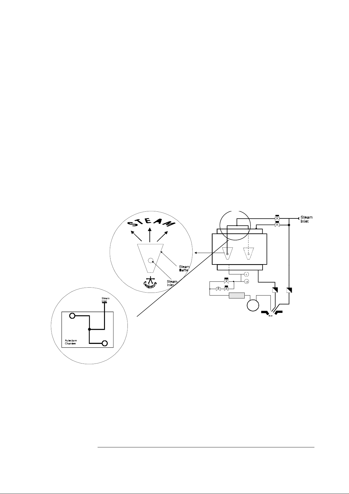
Steam Inlet
Steam inlet piping and manifolds shall be designed and constructed
to distribute steam uniformly throughout the chamber.
Air Inlet
Air entering the chamber shall be filtered if the air is subsequently in
contact with the Product.
Air inlet filters for vacuum break and admission of compressed air
shall be a microbial retentive membrane filter. The pore size of the
5
01/05/99 GMP_.doc Issue 1 - Jan-97
© Getinge 1997
Page 8

GEV
and
GEC
filter shall be according to specific regulatory and product
requirements, but shall generally be less than 0.22 µm.
Heat Exchangers
Internal Heat Exchanger - GEV
The internal heat exchangers shall be of sanitary design
and fabricated from the same material as the chamber
(usually Stainless Steel type 3161 ) and designed to negate
the possibility of leakage of coolant into the chamber or
Process System.
The heat exchanger system / control system shall
incorporate a Leak Test program to periodically check the
integrity of the Heat Exchangers.
External Heat Exchanger - GEC
The external heat exchangers shall be of sanitary design
with process contact surfaces fabricated from the same
material as the chamber (usually Stainless Steel type 316
and designed to negate the possibility of leakage of coolant
into the chamber or Process System.
Generally, where a plate heat exchanger is used, it shall
incorporate a dual gasket system.
1
1
Type 316 ‘L’ or ‘Ti’ , etc according to local practice or requirements
6
01/05/99 GMP_.doc Issue 1 - Jan-97
© Getinge 1997
Page 9

Validation Ports
A minimum of one test connection for the entry of thermocouple
temperature sensors shall be fitted in an accessible location.
As a guide, one port for each two load modules shall be provided.
Each load module is 1.0 to 1.3 m deep. This is subject to practicality
to be assessed in each case.
Connection shall be a minimum of 50 mm diameter to accept a
minimum of 12 thermocouple sensors.
Insulation
[All pipes operating above 60°C, or carrying cold water shall be
insulated. However, it may be impractical to insulate all pipes in this
definition. As a guide, pipes greater in length more than 10 times
their external diameter(10D) shall be insulated. Generally, incoming
water lines shall be insulated up to the first point of use. In most
cases, insulation is only practical after installation of the sterilizer.]
Cleaning
Internal surfaces of the chamber shall be smooth and crevice free.
The surfaces shall be polished to provide a minimum Ra value of
0.63 µm. Internal corners shall be radiused with a minimum 50 mm
radius.
The internal surface of the door shall have a surface finish similar to
the internal surface of the chamber.
The internal surface of chamber ports (nozzles) shall have a surface
finish similar to the internal surface of the chamber.
Fascia and Bioseal Panels
It shall be possible to clean the front surfaces of the fascia and
bioseal panels.
[All gaps between fixed panels and all gaps between the fascia and
the adjacent walls / floor shall be filled with suitable sealant after
installation on site.]
All areas behind fascia panels shall be accessible for cleaning.
Where required for access for cleaning, or for access for
maintenance, fascia panels shall be hinged to open.
7
01/05/99 GMP_.doc Issue 1 - Jan-97
© Getinge 1997
Page 10

GEV
and
Internal Chamber Fitments
Loading Rails and Equipment fitted to chamber
It shall be possible to remove internal loading equipment fixings
(rails, rollers) for periodic cleaning and maintenance.
Strainers
All chamber drain ports shall be fitted with a removable mesh
strainer to prevent debris from entering the chamber drain piping.
(The mesh shall be removable from inside the chamber for routine
cleaning by the machine operator.)
Internal Liner (GEV)
The internal liner of the GEV sterilizer shall be removable for
cleaning.
There shall be no ‘hidden’ areas that are inaccessible.
GEC
Internal Distribution Plate (GEC)
The internal distribution of the GEC sterilizer shall be removable for
cleaning.
8
01/05/99 GMP_.doc Issue 1 - Jan-97
© Getinge 1997
Page 11

GE
and
Control System
Temperature Control
Chamber Temperature will be controlled on a temperature or
pressure basis according to cycle and product requirements. In
either case, the Exposure Period shall be controlled according to
temperature - the lowest temperature of the chamber environment
and product.
GEV
GEC
For non-liquids cycles, this will generally be according to the
Chamber Drain temperature only (it is assumed, and verified during
qualification, that the chamber drain is the coolest part of the
chamber).
For liquids, where the liquid volume is greater then 100 ml, the
exposure period shall be controlled according to chamber drain and
load temperature.
By default, Exposure Period control shall always be by Chamber
Drain, and if fitted, Load Temperature sensors.
Temperature Control
Chamber Temperature will be controlled according to the
temperature of the circulating water. Exposure Period shall be
controlled according to temperature - the lowest temperature of the
product sensors fitted.
GE
and
GEV
Condensate Control
A bleed valve (drain valve by-pass) shall be installed in the chamber
drain line. This shall be opened during the heating and exposure
phases to eliminate condensate.
The bleed ensures a steady flow of steam across the control and
verification sensors.
Means shall be provided to detect a blockage of the bleed valve.
High condensate level shall activate an alarm within the control
system, but shall not abort the process. If the temperature at the
control sensor is depressed by the presence of condensate, the
process shall automatically abort.
9
01/05/99 GMP_.doc Issue 1 - Jan-97
© Getinge 1997
Page 12

Pressure Instruments
Pressure gauges, transducers and other capillary lines connecting
instrumentation to the chamber, shall comply with the ‘Dead Leg’
requirement above. If impractical, pressure transmitting liquid filled
diaphragm or electronic transducer systems shall be used.
In case of use of electronic systems relying on an electric power
supply, for safety, a mechanical gauge (also complying with this
specification) shall be fitted in the service area.
Process Recorder
As a minimum, temperature and pressure values shall be recorded
on a time base during each process cycle. This shall be
independent of the control system or designed to indicate
differences between the controlled and recorded values. This
recorder may be included in the optional ‘Cycle Printer’ detailed
below.
Reference Instrument
Independent reference instruments (verification sensors) shall be
fitted to monitor temperature sensors and pressure sensors
controlling the process.
The verification sensors shall be independent of the control system
in respect of the actual sensor, excitation circuits, amplifiers and
scaling and calibration.
For non-liquids cycles, the verification temperature sensor shall be a
second RTD sensor located in the chamber drain pipework (the
Chamber Drain sensor may be dual element - one element
connected to the controller and the other to the monitoring system).
For liquid cycles, a dual element load temperature sensors is
required. One element of the probe shall be connected to the
controller, and the other shall be connected to the monitoring
system.
A verification pressure sensor is required.
Temperature Sensor Accuracy
This shall be according to local codes and practices.
Generally Pt100 RTD sensors according to IEC 751, and with an
accuracy better than ± 0.2°C shall be used.
10
01/05/99 GMP_.doc Issue 1 - Jan-97
© Getinge 1997
Page 13

Alarm Systems
These shall be designed to continuously monitor conditions that are
critical to the sterilization process in order to ensure personnel
safety, equipment safety and product quality and integrity.
All alarms that occur during a process shall be recorded. The
system shall register concurrent alarms.
Alarms shall include audible and visual indicators. Means to silence
audible alarms shall be provided. Silencing the audible alarm shall
not cancel the visual alarm, until the alarm is acknowledged or
cleared. When silenced for one alarm, the audible alarm shall
remain active for other alarms.
Alarms are segregated into three types:
Fatal - those which cause the process to stop. Operator to decide
whether the cycle shall be continued or aborted. These include, but
are not limited to:
• Intentional abort by operator - operation of 'Stop' button
• Power failure for more than pre-set time
• Time-out of process or equipment critical phases - where process
efficacy would be affected or equipment damage would occur
• Failure of temperature and pressure sensors.
• Door lock failure (loss of 'closed' or 'locked' indication)
GEC
GEV
• Pump Failure (COS Ø pump monitor system error)
• Fan Failure (COS Ø fan watch system error)
Non-fatal - those which allow process to continue. These include,
but are not limited to:
• High condensate level detected
• Interlock test errors
11
01/05/99 GMP_.doc Issue 1 - Jan-97
© Getinge 1997
Page 14

Optional Items
Cycle Printer
An automatic measurement and recording system shall be provided.
The following data and parameters shall be recorded, as a minimum:
Header, including:
Date Sterilizer I.D.
Load Identification Operator I.D. & Signature
Cycle Start Time (real time) Cycle Type selected
Cycle Parameters:
Value of adjustable parameters
Set sterilizing time and temperature
Logged on adjustable time base:
Chamber pressure Load temperature(s) (note 2)
Chamber Drain Temperature (note 1) Verification sensor values (note 3)
Note 1: Applies to Non-Liquids cycles only.
Note 2: Applies to Liquids cycles only.
Note 3: See ‘Reference Instrument’ below.
The sterilizer & process I.D. shall be identified at the top of each
page of the process log such that the specific process run can be
uniquely identified. Phase changes within the process shall be
indicated.
PACS Supervisor
The PACS Supervisor is a combination Reference Instrument and
Process Recorder.
The PACS Supervisor is provided with independent sensors for
temperature and pressure. These are then the 'Verification Sensors'
mentioned above.
The verification sensors shall monitor the control sensors and may
indicate an alarm if the sensors deviate by more than a pre-set limit
during the process.
The values of the control temperature sensors, verification sensors
and pressure sensor shall be combined in a data acquisition system
(i.e. on a single data printout). All alarms shall be noted in the
documentation.
12
01/05/99 GMP_.doc Issue 1 - Jan-97
© Getinge 1997
Page 15

In-situ Air Filter Sterilization (AFS)
This applies to microbial retentive air filters in a stainless steel
housing, used for vacuum break or admission of compressed air to
the chamber. When AFS is specified:
A cycle shall be provided to automatically sterilize the filter element
within the housing. The piping system upstream of the filter, to the
first isolating valve, shall be sterilized as part of each process.
It shall be possible to record and validate each cycle. The process
record shall indicate and report its satisfactory completion.
The drain of the filter housing and/or upstream piping is equipped
with a temperature sensor (Control Sensor), and the cycle is
operated according to a sequence for a gravity displacement
sterilization cycle, with an added cooling phase. See separate sheet
for detailed description.
In-situ Air Filter Integrity Test (AFT)
This applies to microbial retentive air filters in a stainless steel
housing, used for vacuum break or admission of compressed air to
the chamber. When AFT is specified:
A cycle shall be provided to automatically test the integrity of the
filter element within the housing.
It shall be possible to record and validate each cycle. The process
record shall indicate and report its satisfactory completion.
The filter housing shall be equipped with a pressure sensor and
ancillary equipment to enable a forward flow pressure decay, water
intrusion test, or similar, to be performed.
The control system shall indicate 'Pass' or 'Fail' on termination.
The test shall be designed according to procedures and parameters
specified by the filter manufacturer. The filter manufacturer shall
provide approval in writing of the test parameters and procedure.
13
01/05/99 GMP_.doc Issue 1 - Jan-97
© Getinge 1997
Page 16

Sanitary Piping system (SAN)
When specified, this will be provided in conjunction with stainless
steel Process System piping. All piping and components in the
Process System shall be of sanitary specification.
The features of a 'sanitary' system include:
• The system shall be completely self draining, and shall not retain
moisture. The 'system' includes all components, fittings and
piping in the Process System.
• The system shall be free of crevices where dirt might accumulate.
Internal surfaces shall be cleanable. Optionally, the chamber
shall have a higher grade surface finish - E.P. or high mechanical
polish (e.g. Ra=0.2µm).
• When connections can be avoided, the components shall be
welded in place. However, consideration is given to removal of
components and assemblies for cleaning and inspection.
• Connections shall be made using approved (to 3A or IDF
standard) sanitary style fittings, such as tri-clamps. Screwed
connections shall not be used.
• Valves shall be of sanitary design, such as diaphragm type
valves. Globe valves shall not be used.
Optional items for Sanitary Specification
♦ Material specifications and mill sheet certificates may be provided
for piping and components (in Getinge’s Extended Documentation
package).
♦ Weld Records may be provided.
◊ Weld samples shall be produced before and after the
machine construction to indicate repeatable performance
of the welding equipment.
◊ Welds shall be identified by reference number (e.g.
engraving or sketch)
◊ Welds shall be inspected by video boroscope indicating
reference numbers as above.
◊ Welding equipment parameters should be printed and
included in the weld documentation.
14
01/05/99 GMP_.doc Issue 1 - Jan-97
© Getinge 1997
 Loading...