GE GIE21GSHBSS, GIE21GSHCSS, GIE21GTHBBB, GIE21GTHBWW, GIE21GTHCBB Installation Guide
...
GE Appliances
Part Install Instructions
Breaker Trip Kit
WR49X27506
|
! |
IMPORTANT SAFETY NOTICE |
|
|
! |
WARNING |
|
|
|
|
|
||
The information in this part instruction is intended for use by |
|
To avoid personal injury, disconnect power before servicing this |
||||
individuals possessing adequate backgrounds of electrical, |
|
appliance. If electrical power is required for diagnosis or test |
||||
electronic and mechanical experience. Any attempt to repair a |
|
purposes, disconnect the power immediate after performing the |
||||
major appliance may result in personal injury and property |
|
necessary checks. RECONNECT ALL GROUNDING DEVICES If |
||||
damage. The manufacturer or seller cannot be responsible for the |
|
grounding wires, screws, straps, c ips, uts, or washers used to |
||||
interpretation of this information, nor can it assume any liability in |
|
complete a path to ground are removed for service, they must be |
||||
connection with its use. |
|
returned to their original position a d properly fastened. |
||||
|
|
|
||||
Parts Included: |
|
Tools Required: |
||||
• |
|
PTC starter (relay) - WR55X22042 |
|
• |
|
Phillips h adOnlyscrewdriver |
• |
|
Overload ProtectorWR87X27188 |
|
• |
|
¼” nut driv r |
• |
|
Protector Cover - WR01X27243 |
Use• Small flat blade screwdriver |
|||
• |
|
Instruction Sheet |
|
|
|
|
Following steps coverInternalthe repair for branch circuit AFCI or
AFCI+GFCI dual function circuit breakers tripping with 21 Cu Ft top freezer refrigerators.
Step 1- Disconnect power to he r frig rator.
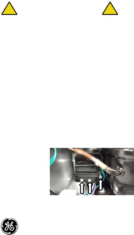
Step 2- Remove the rear access cover by removing six ¼‘” hex head screws. Step 3- RemoveLISthree Phillips head screws from the protector cover.
|
|
Continued… |
GE Appliances |
1 |
WR00X27596 |
Louisville, KY 40225 |

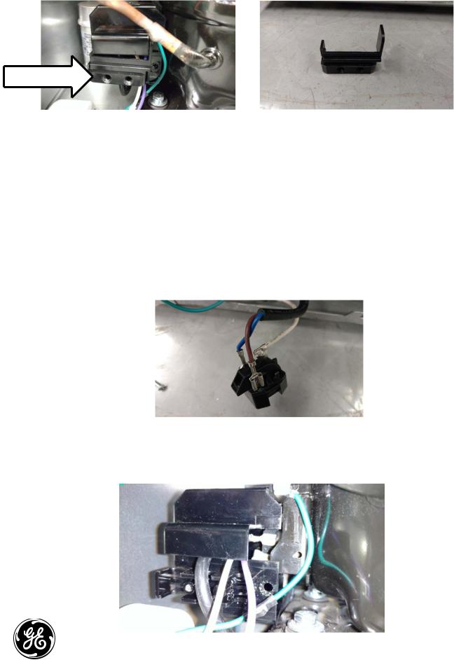
Step 4- Remove the plastic wire holder. A small screwdriver may help to pry the holder from the cover.
Wire holder
Step 5- Remove the protector cover.
•Rotate the back of the cover to the left.
•Then rotate the top of the cover away from the compressor.
Step 6- Remove the PTC by pulling the relay to the left of the compressor. DO NOT pry or wiggle the
Step 10Place the wires into the groove of the relay cover and slide the cover into place.
PTC side to side to remove, this can damage compressor pins. Disconnect wires and discard the PTC. |
||||
|
|
|
|
Only |
Step 7- Remove the overload by pulling the overload to the l ft of the compressor and replace with the |
||||
new overload. |
|
|
Use |
|
Step 8- Connect the wires to the new startup relay. |
|
|||
Pin 1-White |
|
|
||
|
|
|
||
Pin 2-Blue |
|
|
|
|
Pin 3-Brown |
|
1 |
|
|
Pin 4-not used |
2 |
|
|
|
|
|
|
4 |
|
|
|
|
3 |
|
Step 9- Connect the new relay to the compressor. |
|
|
||
LIS |
Internal |
|
|
|
|
|
|
|
|
|
|
Continued… |
GE Appliances |
2 |
WR00X27596 |
Louisville, KY 40225 |
 Loading...