

Page 1

Gateway™ 7450R Server
System Manual
March 2001
Page 2

Notices
Copyright © 2001 Gateway, Inc.
All Rights Reserved
4545 Town Centre Court
San Diego, CA 9212 1 USA
All Rights Reserved
This publication is protected by copyright and all rights are reserved. No part of it may be reproduced or
transmitted by any means or in any form, without prior consent in writing from Gateway.
The information in this manual has been carefully checked and is believed to be accurate. However, changes
are made periodically. These changes are incorporated in newer publication editions. Gateway may improve
and/or change products described in this publication at any time. Due to continuing system improvements,
Gateway is not responsible for inaccurate information which may appear in this manual. For the latest product
updates, consult the Gateway Web site at www.gateway.com. In no event will Gateway be liable for direct,
indirect, special, exemplary, incidental, or consequential damages resulting from any defect or omission in
this manual, even if advised of the possibility of such damages.
In the interest of continued product development, Gateway reserves the right to make improvements in this
manual and the products it describes at any time, without notices or obligation.
Trademark Acknowledgments
1-800-GATEWAY, ActiveCPR, ALR, AnyKey, black-and-white spot design, CrystalScan, Destination, DestiVu,
EZ Pad, EZ Point, Field Mouse, Gateway 2000, Gateway Country, gateway .net, Gateway stylized logo, Perfect
Scholar, Solo, TelePath, Vivitron, stylized “G” design, and “You’ve got a friend in the business ” slogan are
registered trademarks and black-and-white spotted box logo, GATEWAY, Gateway Astro, Gateway@Work,
Gateway Connected touch pad, Gateway Connected music player, Gateway Cyber:)Ware, Gateway
Education:)Ware, Gateway Flex Case, Gateway Gaming:)Ware, Gateway GoBack, Gateway Gold, Gateway
Learning:)Ware, Gateway Magazine, Gateway Micro Server, Gateway Money:)Ware, Gateway Music:)Ware,
Gateway Networking Solutions, Gateway Online Network (O.N.) solution, Gateway Photo:)Ware, Gateway
Professional PCs, Gateway Profile, Gateway Solo, green stylized GATEWAY, green stylized Gateway logo,
Gateway T eacher:)Ware, Gateway Video:)Ware, HelpSpot, InforManager, Just click it!, Learn@Gateway, Kids
BackPack, People Rule, SERVE-TO-ORDER, Serv er Watchdog, SpotShop, Spotshop.com, and Your:)Ware
are trademarks of Gateway, Inc. Intel, Intel Inside logo, and Pentium are registered trademarks and MMX is
a trademark of Intel Corporation. Microsoft, MS, MS-DOS, an d Windows are trademarks or registered
trademarks of Microsoft Corporation. All other product names mentioned herein are used f or identification
purposes only, and may be the trademarks or registered trademarks of their respective companies.
Page 3

Contents
Preface. . . . . . . . . . . . . . . . . . . . . . . . . . . . . . . . . . . . . . . . . . . . . . . . . . . . . . . . . . . . . . v
Conventions used in this manual . . . . . . . . . . . . . . . . . . . . . . . . . . . . . . . . . . . . . . . v
Getting additional information . . . . . . . . . . . . . . . . . . . . . . . . . . . . . . . . . . . . . . . . . . vi
1 System Features . . . . . . . . . . . . . . . . . . . . . . . . . . . . . . . . . . . . . . . . . . . . . . . . 1
Standard features . . . . . . . . . . . . . . . . . . . . . . . . . . . . . . . . . . . . . . . . . . . . . . . . . . . 1
Front panel . . . . . . . . . . . . . . . . . . . . . . . . . . . . . . . . . . . . . . . . . . . . . . . . . . . . . . . . 2
Control Panel . . . . . . . . . . . . . . . . . . . . . . . . . . . . . . . . . . . . . . . . . . . . . . . . . . . . . . . 3
Back panel . . . . . . . . . . . . . . . . . . . . . . . . . . . . . . . . . . . . . . . . . . . . . . . . . . . . . . . . . 4
Interior of system . . . . . . . . . . . . . . . . . . . . . . . . . . . . . . . . . . . . . . . . . . . . . . . . . . . . 5
System board . . . . . . . . . . . . . . . . . . . . . . . . . . . . . . . . . . . . . . . . . . . . . . . . . . . . . . 6
Hot-plug backplane . . . . . . . . . . . . . . . . . . . . . . . . . . . . . . . . . . . . . . . . . . . . . . . . . . 8
Control panel board . . . . . . . . . . . . . . . . . . . . . . . . . . . . . . . . . . . . . . . . . . . . . . . . . . 9
Riser card . . . . . . . . . . . . . . . . . . . . . . . . . . . . . . . . . . . . . . . . . . . . . . . . . . . . . . . . 10
2 System Setup . . . . . . . . . . . . . . . . . . . . . . . . . . . . . . . . . . . . . . . . . . . . . . . . . . 11
Setting up the server . . . . . . . . . . . . . . . . . . . . . . . . . . . . . . . . . . . . . . . . . . . . . . . . 11
Starting the server . . . . . . . . . . . . . . . . . . . . . . . . . . . . . . . . . . . . . . . . . . . . . . . . . . 12
Understanding the Power-On Self-Test . . . . . . . . . . . . . . . . . . . . . . . . . . . . . . 13
Setting up the operating system . . . . . . . . . . . . . . . . . . . . . . . . . . . . . . . . . . . . 13
Turning off the server . . . . . . . . . . . . . . . . . . . . . . . . . . . . . . . . . . . . . . . . . . . . . . . 14
Resetting the server . . . . . . . . . . . . . . . . . . . . . . . . . . . . . . . . . . . . . . . . . . . . . . . . 15
3 Case Access . . . . . . . . . . . . . . . . . . . . . . . . . . . . . . . . . . . . . . . . . . . . . . . . . . . 17
Preventing static electricity discharge . . . . . . . . . . . . . . . . . . . . . . . . . . . . . . . . . . . 17
Opening the case . . . . . . . . . . . . . . . . . . . . . . . . . . . . . . . . . . . . . . . . . . . . . . . . . . 18
Removing the top panel . . . . . . . . . . . . . . . . . . . . . . . . . . . . . . . . . . . . . . . . . . 18
Closing the case . . . . . . . . . . . . . . . . . . . . . . . . . . . . . . . . . . . . . . . . . . . . . . . . . . . 20
Replacing the top panel . . . . . . . . . . . . . . . . . . . . . . . . . . . . . . . . . . . . . . . . . . 20
4 Replacing and Adding Internal Devices . . . . . . . . . . . . . . . . . . . . . . . . 21
Drives . . . . . . . . . . . . . . . . . . . . . . . . . . . . . . . . . . . . . . . . . . . . . . . . . . . . . . . . . . . . 21
Preparing to replace or add a drive . . . . . . . . . . . . . . . . . . . . . . . . . . . . . . . . . 21
Drive cabling information . . . . . . . . . . . . . . . . . . . . . . . . . . . . . . . . . . . . . . . . . 22
Replacing the diskette drive . . . . . . . . . . . . . . . . . . . . . . . . . . . . . . . . . . . . . . . 22
Installing a CD drive . . . . . . . . . . . . . . . . . . . . . . . . . . . . . . . . . . . . . . . . . . . . . 24
Replacing the CD drive assembly . . . . . . . . . . . . . . . . . . . . . . . . . . . . . . . . . . 25
Replacing a hot-plug drive . . . . . . . . . . . . . . . . . . . . . . . . . . . . . . . . . . . . . . . . 27
Contents i
Page 4

Adding a hot-plug drive . . . . . . . . . . . . . . . . . . . . . . . . . . . . . . . . . . . . . . . . . . .29
Memory . . . . . . . . . . . . . . . . . . . . . . . . . . . . . . . . . . . . . . . . . . . . . . . . . . . . . . . . . . .31
Replacing memory . . . . . . . . . . . . . . . . . . . . . . . . . . . . . . . . . . . . . . . . . . . . . . .32
Adding memory . . . . . . . . . . . . . . . . . . . . . . . . . . . . . . . . . . . . . . . . . . . . . . . . .33
Processors . . . . . . . . . . . . . . . . . . . . . . . . . . . . . . . . . . . . . . . . . . . . . . . . . . . . . . . .34
Replacing the primary processor . . . . . . . . . . . . . . . . . . . . . . . . . . . . . . . . . . . .34
Replacing the secondary processor . . . . . . . . . . . . . . . . . . . . . . . . . . . . . . . . .36
Adding a secondary processor . . . . . . . . . . . . . . . . . . . . . . . . . . . . . . . . . . . . .39
Replacing the battery . . . . . . . . . . . . . . . . . . . . . . . . . . . . . . . . . . . . . . . . . . . . . . . .40
Expansion cards . . . . . . . . . . . . . . . . . . . . . . . . . . . . . . . . . . . . . . . . . . . . . . . . . . . .43
Replacing an expansion card . . . . . . . . . . . . . . . . . . . . . . . . . . . . . . . . . . . . . .43
Adding an expansion card . . . . . . . . . . . . . . . . . . . . . . . . . . . . . . . . . . . . . . . . .45
Replacing the power supply . . . . . . . . . . . . . . . . . . . . . . . . . . . . . . . . . . . . . . . . . . .48
Replacing a blower . . . . . . . . . . . . . . . . . . . . . . . . . . . . . . . . . . . . . . . . . . . . . . . . . .50
Replacing a fan . . . . . . . . . . . . . . . . . . . . . . . . . . . . . . . . . . . . . . . . . . . . . . . . . . . . .52
Replacing the control panel board . . . . . . . . . . . . . . . . . . . . . . . . . . . . . . . . . . . . . .53
Replacing the hot-plug backplane . . . . . . . . . . . . . . . . . . . . . . . . . . . . . . . . . . . . . .54
Replacing the riser card . . . . . . . . . . . . . . . . . . . . . . . . . . . . . . . . . . . . . . . . . . . . . .55
Replacing the system board . . . . . . . . . . . . . . . . . . . . . . . . . . . . . . . . . . . . . . . . . . .57
5 Using the BIOS Setup Utility . . . . . . . . . . . . . . . . . . . . . . . . . . . . . . . . . . . .61
About the BIOS Setup utility . . . . . . . . . . . . . . . . . . . . . . . . . . . . . . . . . . . . . . . . . . .61
Updating the BIOS . . . . . . . . . . . . . . . . . . . . . . . . . . . . . . . . . . . . . . . . . . . . . . . . . .63
BIOS Recovery . . . . . . . . . . . . . . . . . . . . . . . . . . . . . . . . . . . . . . . . . . . . . . . . . . . . .63
Setting the system board jumpers and switches . . . . . . . . . . . . . . . . . . . . . . . . . . .64
The CMOS Clear jumper . . . . . . . . . . . . . . . . . . . . . . . . . . . . . . . . . . . . . . . . . .64
Setting the switches . . . . . . . . . . . . . . . . . . . . . . . . . . . . . . . . . . . . . . . . . . . . . .65
6 Managing the Server . . . . . . . . . . . . . . . . . . . . . . . . . . . . . . . . . . . . . . . . . . . .67
Avoiding power source problems . . . . . . . . . . . . . . . . . . . . . . . . . . . . . . . . . . . . . . .67
Surge suppressors . . . . . . . . . . . . . . . . . . . . . . . . . . . . . . . . . . . . . . . . . . . . . . .67
Line conditioners . . . . . . . . . . . . . . . . . . . . . . . . . . . . . . . . . . . . . . . . . . . . . . . .68
Uninterruptible power supplies . . . . . . . . . . . . . . . . . . . . . . . . . . . . . . . . . . . . . .68
Maintain and manage your hard drive . . . . . . . . . . . . . . . . . . . . . . . . . . . . . . . . . . .68
Hard drive maintenance utility . . . . . . . . . . . . . . . . . . . . . . . . . . . . . . . . . . . . . .68
Hard drive management practices . . . . . . . . . . . . . . . . . . . . . . . . . . . . . . . . . . .69
Protecting the server against viruses . . . . . . . . . . . . . . . . . . . . . . . . . . . . . . . . . . . .72
System administration and control . . . . . . . . . . . . . . . . . . . . . . . . . . . . . . . . . . . . . .73
ManageX Event Manager . . . . . . . . . . . . . . . . . . . . . . . . . . . . . . . . . . . . . . . . .73
SNMP agent . . . . . . . . . . . . . . . . . . . . . . . . . . . . . . . . . . . . . . . . . . . . . . . . . . . .73
System security . . . . . . . . . . . . . . . . . . . . . . . . . . . . . . . . . . . . . . . . . . . . . . . . .76
System recovery . . . . . . . . . . . . . . . . . . . . . . . . . . . . . . . . . . . . . . . . . . . . . . . . . . . .77
Creating a startup diskette . . . . . . . . . . . . . . . . . . . . . . . . . . . . . . . . . . . . . . . . .77
ii Gateway 7450R Server System Manual
Page 5

Using your Server Companion CD . . . . . . . . . . . . . . . . . . . . . . . . . . . . . . . . . . 78
7 Troubleshooting . . . . . . . . . . . . . . . . . . . . . . . . . . . . . . . . . . . . . . . . . . . . . . . . 79
Introduction . . . . . . . . . . . . . . . . . . . . . . . . . . . . . . . . . . . . . . . . . . . . . . . . . . . . . . . 79
Troubleshooting checklist . . . . . . . . . . . . . . . . . . . . . . . . . . . . . . . . . . . . . . . . . . . . 79
Verifying your configuration . . . . . . . . . . . . . . . . . . . . . . . . . . . . . . . . . . . . . . . 79
Troubleshooting guidelines . . . . . . . . . . . . . . . . . . . . . . . . . . . . . . . . . . . . . . . . 80
Troubleshooting the battery installation . . . . . . . . . . . . . . . . . . . . . . . . . . . . . . 80
CD problems . . . . . . . . . . . . . . . . . . . . . . . . . . . . . . . . . . . . . . . . . . . . . . . . . . . . . . 81
Hard drive problems . . . . . . . . . . . . . . . . . . . . . . . . . . . . . . . . . . . . . . . . . . . . . . . . 81
Memory and processor problems . . . . . . . . . . . . . . . . . . . . . . . . . . . . . . . . . . . . . . 82
Peripheral/Adapter problems . . . . . . . . . . . . . . . . . . . . . . . . . . . . . . . . . . . . . . . . . . 82
Printer problems . . . . . . . . . . . . . . . . . . . . . . . . . . . . . . . . . . . . . . . . . . . . . . . . . . . 84
System problems . . . . . . . . . . . . . . . . . . . . . . . . . . . . . . . . . . . . . . . . . . . . . . . . . . . 85
Video problems . . . . . . . . . . . . . . . . . . . . . . . . . . . . . . . . . . . . . . . . . . . . . . . . . . . . 86
Error codes and test points . . . . . . . . . . . . . . . . . . . . . . . . . . . . . . . . . . . . . . . . . . . 88
A Safety, Regulatory, and Notices . . . . . . . . . . . . . . . . . . . . . . . . . . . . . . . . 95
B System Specifications . . . . . . . . . . . . . . . . . . . . . . . . . . . . . . . . . . . . . . . . 107
System Specifications . . . . . . . . . . . . . . . . . . . . . . . . . . . . . . . . . . . . . . . . . . . . . . 107
Mechanical specifications . . . . . . . . . . . . . . . . . . . . . . . . . . . . . . . . . . . . . . . . 108
Environmental specifications . . . . . . . . . . . . . . . . . . . . . . . . . . . . . . . . . . . . . . 108
Electrical specifications . . . . . . . . . . . . . . . . . . . . . . . . . . . . . . . . . . . . . . . . . . 109
Index. . . . . . . . . . . . . . . . . . . . . . . . . . . . . . . . . . . . . . . . . . . . . . . . . . . . . . . . . . . . . . 111
Contents iii
Page 6

iv Gateway 7450R Server System Manual
Page 7
Preface
Conventions used in this manual
Throughout this manual, you will see the following conventions:
Convention Description
ENTER Keyboard key names are printed in small capitals.
C
TRL+ALT+DEL A plus sign means to press the keys at the same time.
Setup Commands to be entered, options to select, and messages that
appear on your monitor are printed in bold.
User’s Guide Names of publications are printed in italic.
Viewpoint All references to front, rear, left, or right on the server are based
on the server being in a normal, upright position, as viewed from
the front.
Important A note labeled important informs you of special
circumstances.
Caution A caution warns you of possible damage to equipment or
loss of data.
Warning A warning indicates the possibility of personal injury.
Preface v
Page 8

Getting additional information
Log on to the Gateway technical support area at www.gatewayatwork.com to
find information about your system or other Gateway products. Some t ypes
of information you can acc ess are:
■ Hardware driver and program u pdates
■ Technical tips
■ Service agreement information
■ Technical documents and component info rmation
■ Frequently asked questions (FAQs)
■ Documentation for per ipherals or optional co mponents
■ Online technical support
vi Gateway 7450R Server System Manual
Page 9

System Features
Standard features
■ As many as two Intel
Bus (FSB)
■ Four Dual Inline Memory Module (DIMM) sockets, that support up to
4.0 GB of buffered, PC/133 Synchronous Dynamic Random Access
Memory (SDRAM)
■ ATI Rage XL AGP video chipset
■ Two integrated Intel 82559 network controllers providing dual 10/100
LAN support and network con nectors
■ Integrated Super Video Graphics Array (SVGA) vi deo suppo rt with 4 MB
of Synchronous Graphics RAM (SGRAM)
■ Two full-length, full-height, 64-bit, 66 MHz PCI slots on a riser card
■ One 1.44 MB disk ette driv e, on e opti onal CD dri ve, an d at l east one ha rd
drive
■ Integrated voltage regulator modules (VRMs) for both processors
■ Integrated Adaptec AIC 7892 small computer systems interface (SCSI)
controller providing low-voltage differential (LVD) Ultra3 support
®
Pentium III processors with 133 MHz Front Side
1
■ Three-drive hot-plug drive bay supporting Ultra160 single connector
attachment (SCA) drives
■ Keyboard port Personal System/2
port, one video port, two RJ-4 5 LAN ports, an d one Un iversal Serial Bus
(USB) port on the front panel
®
(PS/2), mouse port (PS/2), one serial
System Features 1
Page 10
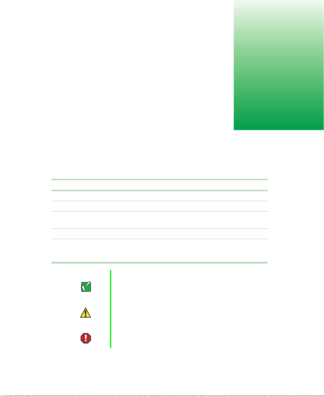
Front panel
CD drive (optional)Control Panel
Hard drive activity LED (3)
Hot-plug drive(s)Hot-plug drive bays (3)
Control panel contain s th e LED ind ica tor s an d the bu tto ns th at c ont rol the
server.
CD drive (optional) plays data or audio CDs.
Diskette d rive writes to and reads from 3.5-inch, 1.44 MB diskettes.
Hot-plug driv e bays (3) includes three drive carriers and as many as three
hot-swappable, hot-plug drives connected to a ho t-plug b ac kplane. Th e driv e
bays support 1.0-inch Ultra160 SCSI drives.
Hot plug drive(s) plug into the hot-plug drive bay(s). The server includes at
least one and may inclu de as many as three.
Hard drive activity LED (3) flashes green when the adjacent hard drive is
accessed.
Hard drive pow er LED (3) glows g reen when the adjacent hard drive has
power, glows amber if the adjacent hard drive has failed, and blinks amber
if the adjacent hard drive is rebuilding.
Hard drive power LED (3)
Diskette drive
2 Gateway 7450R Server System Manual
Page 11
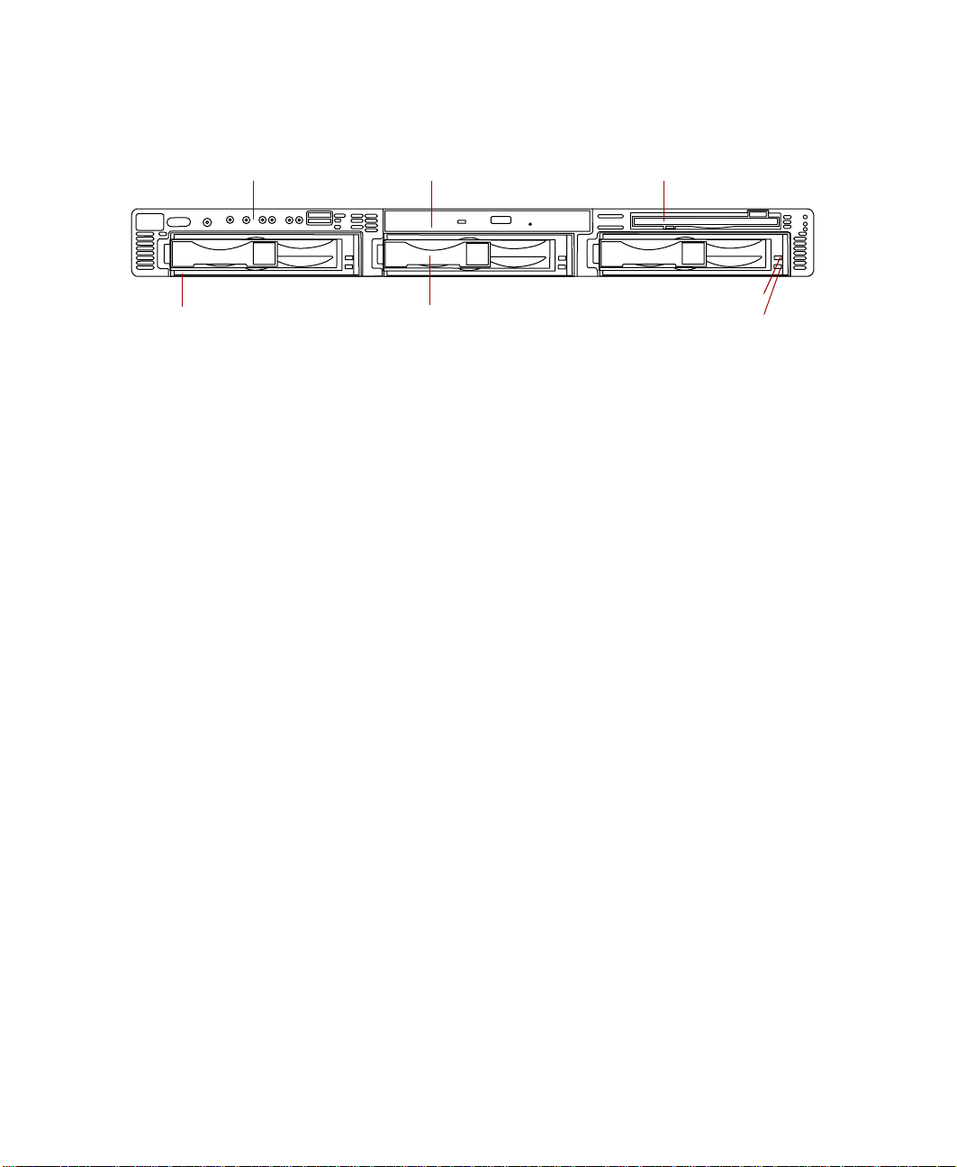
Control Panel
System fault LED
Power LED
Fault LED reset button
Power button
System fault LED glows amber when a hardware or system failure occurs.
Pressing the fault LED reset button turns this LED off, but does not correct
the fault.
Power LED glows green when the serve r has power and flashes green when
the server is in power saving mode. This LED glows amber when AC power
to the server is on, but the internal (DC) power is off which means there is
power to the server but the server is powered down.
Fault LED reset button resets any of the fault LEDs to its original state in
the default mode. This button does not correct or clear the fault. If the fault
condition persists, the appropriate LED will turn on again until the fault is
corrected. This button can be reprogrammed through a BIOS option to
generate a Non-Maskable Interrupt (NMI) when pressed. The NMI function
can produce varied results depending on the software support for NMI
handling.
LAN1 LED
LAN2 LED
Blower fault LED
Fan fault LED
USB port
Power button turns the serve r on and off.
LAN1 LED blinks green when there is traffic on the LAN1 connector. Glows
amber when the LAN1 connector experiences an interruption in connectivity.
LAN2 LED blinks green when there is traffic on the LAN2 connector. Glows
amber when the LAN2 connector experiences an interruption in connectivity.
Blower fault LED glows amber when one of the blowers has failed or entered
an out-of-tolerance sta te.
Fan fault LED glows amber when one of the fans has failed or entered an
out-of-toleran ce state.
USB port provides front panel access for USB peripherals.
System Features 3
Page 12
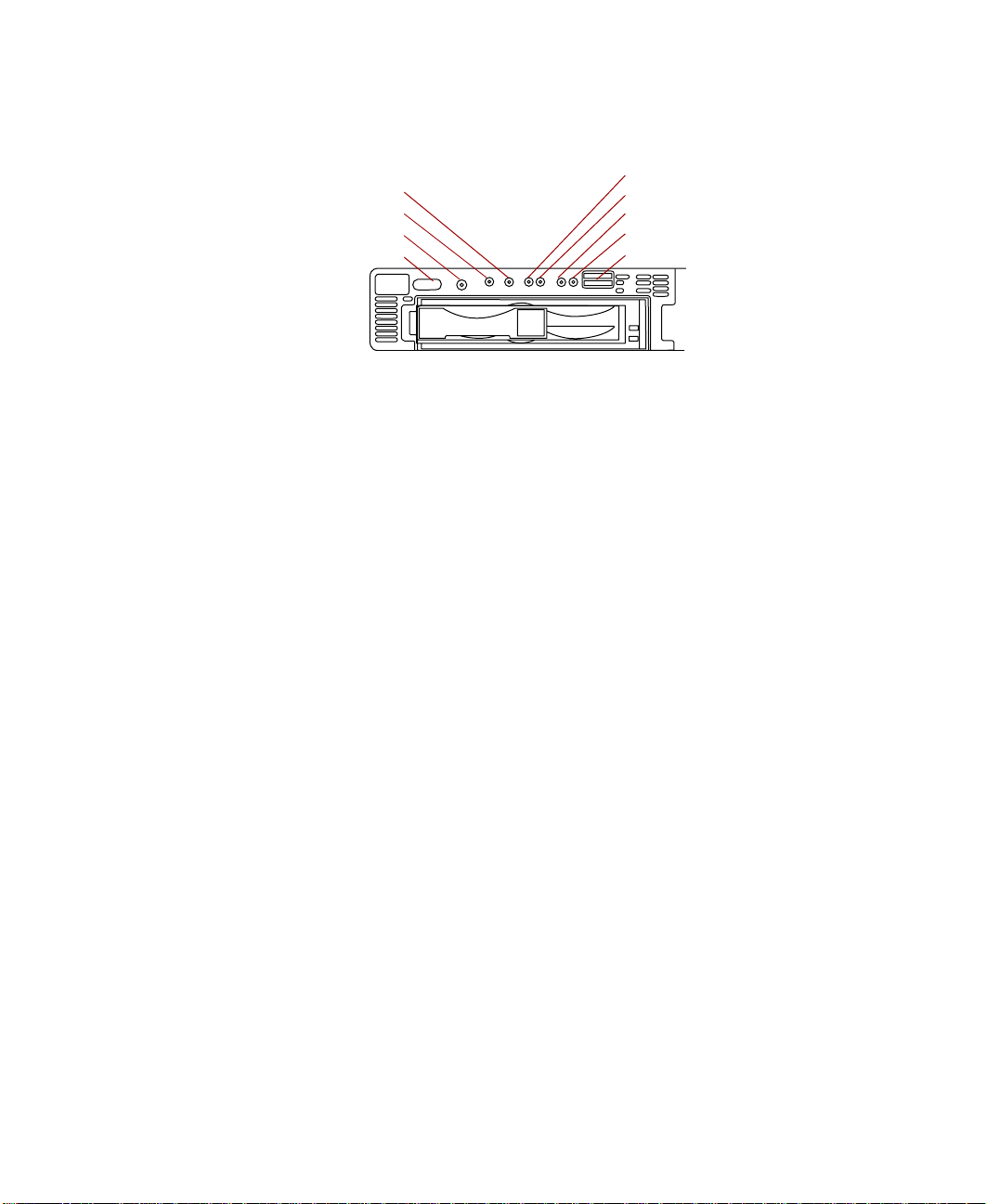
Back panel
Power connector
Keyboard port Serial port
Power connector connects the server power cord. The other end of the power
cord plugs into an AC outlet, uninterruptible power supply (UPS), or power
strip.
Mouse port connects a PS/2-compatible mouse.
LAN2 port lets you connect to a network. The adjacent indicator LEDs show
LAN activity (green) and 100 Mbit speed (amber).
LAN1 port lets you connect to a network. The adjacent indicator LEDs show
LAN activity (green) and 100 Mbit speed (amber).
Keyboard port connects a PS/2-compatible keyboard.
Serial port connects to a serial device.
Video por t connects the monitor interface cable. The video controller is
integrated on the system board.
Mouse port
LAN2 port
Video port
LAN1 port
Expansion card slots (2)
Expansion card slots (2) let you install as many as two full-length, full-height,
64-bit, 66 MHz PCI expansion cards.
4 Gateway 7450R Server System Manual
Page 13
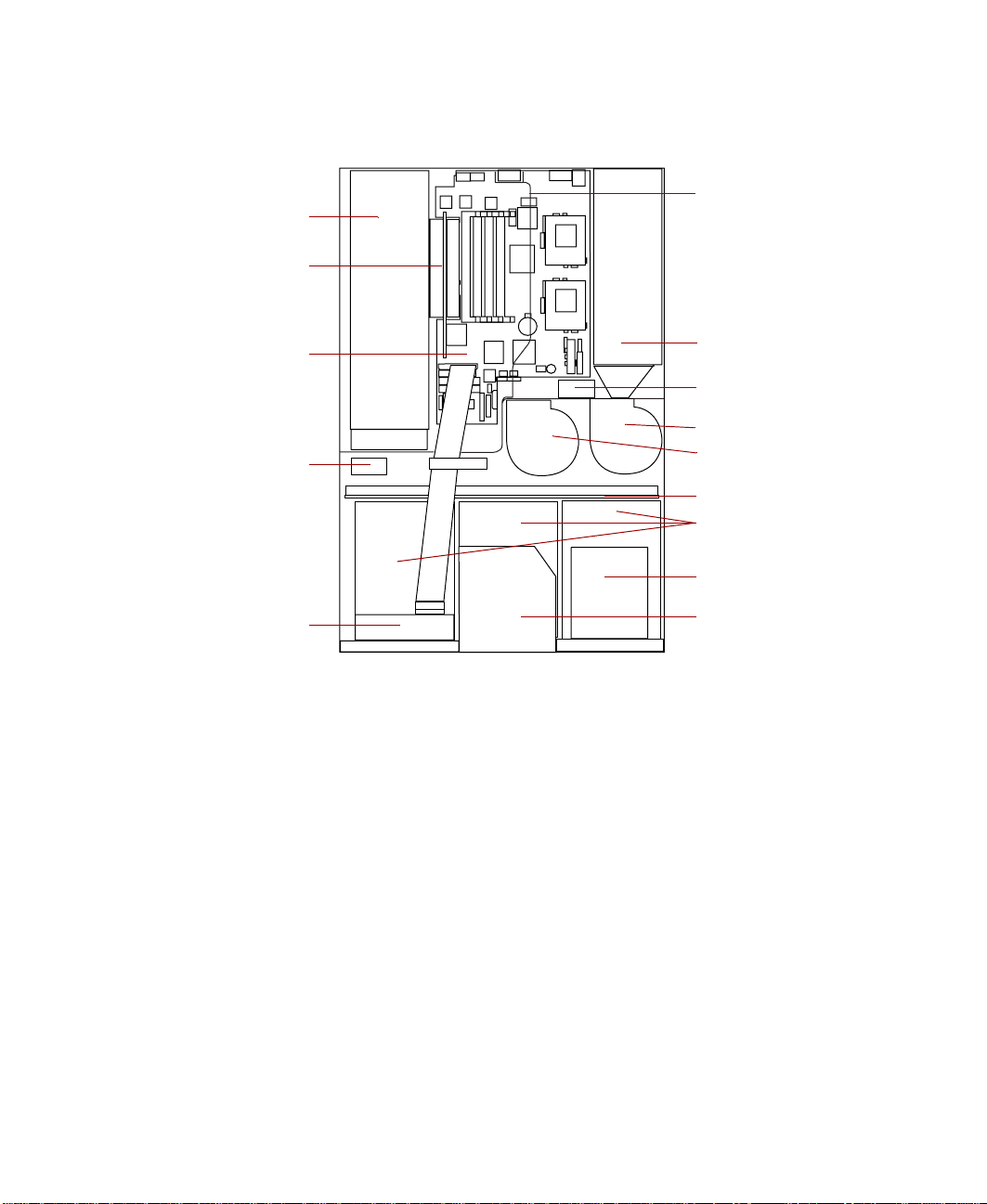
Interior of system
Expansion cards
Riser card
Air baffle
System boa rd
Fan 1
Control panel board
Power supply
Fan 2
Blower 2
Blower 1
Hot-plug backplane
Hot-plug drive bays
Diskette drive
CD drive (o ptional)
Expansion cards you can install as many as two full-length PCI expansion
cards.
Riser card supports as many as two full-length PCI expansion cards.
System board see “System board” on page 6.
Fans provide cooling for the system.
Control panel board contains the indicator LEDs and the butto ns to control
the server. See “Control panel b oard” on page 9 .
Air baffle controls the internal airflow to make sure the thermally sensitive
internal components receive adequate cooling.
Power supply provides power to the system components.
Blowers provide cooling for the system.
Hot-plug backplane provides the control for the hot-plug drives.
System Features 5
Page 14
Hot-plug bays support up to three 1-inch high, 3.5-inch Ultra160 SCA SCSI
hard drives. Empty drive bays contain empty carriers to control airflow and
EMC characteristics.
Diskette d rive reads and writes 1.44-MB diskett es.
CD drive (optional) plays data or audio CDs.
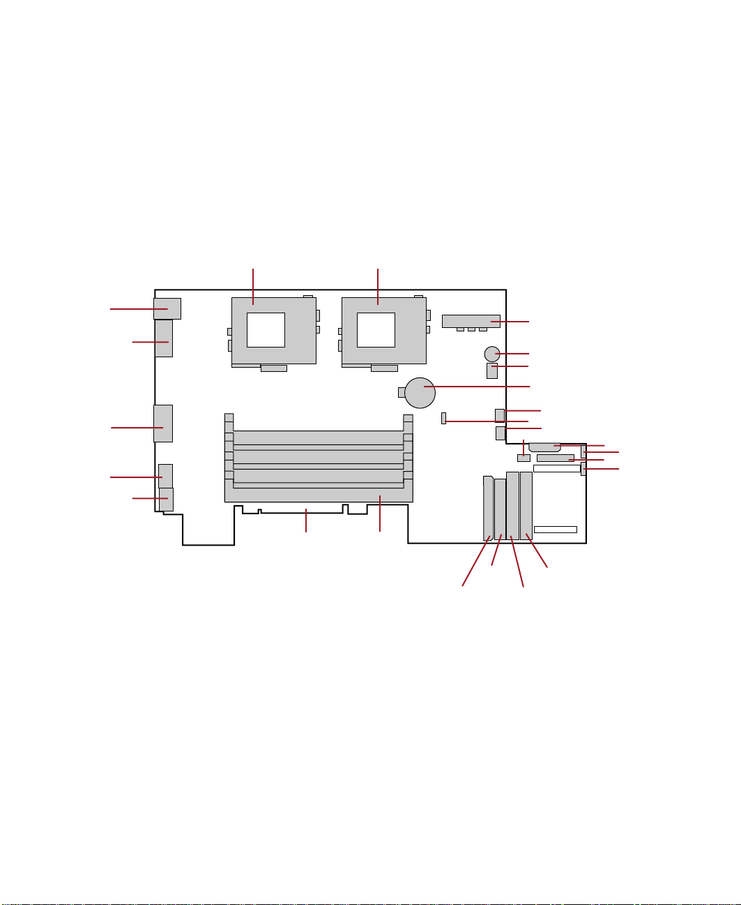
System board
A
Y
X
W
V
U
T
B
C
D
E
F
G
H
I
J
S
Q
R
O
P
K
L
M
N
A Secondary processor socket
B Primary processor socket
C Power connector
D Speaker
E Sw itch b ank SW 1
F Battery
6 Gateway 7450R Server System Manual
Page 15

Blower 2 connector
G
H Jumper J1
I Blower 1 conn ector
J Front panel USB connector
K Power connector
L Fan 2 connec tor
M Front panel connector
N Fan 1 connec tor
O Secondary IDE connector
P Primar y IDE connector
Q Diskette drive conn ector
R Ultra160 SCSI connector
S DIMM slots (4)
T Riser card edge connector
U RJ-45 Ethernet LAN1 connector and LEDs
V RJ-45 Ethernet LAN2 connector and LEDs
W Video connector
X Serial po rt
Y Sta cked keyboard and mouse ports
System Features 7
Page 16
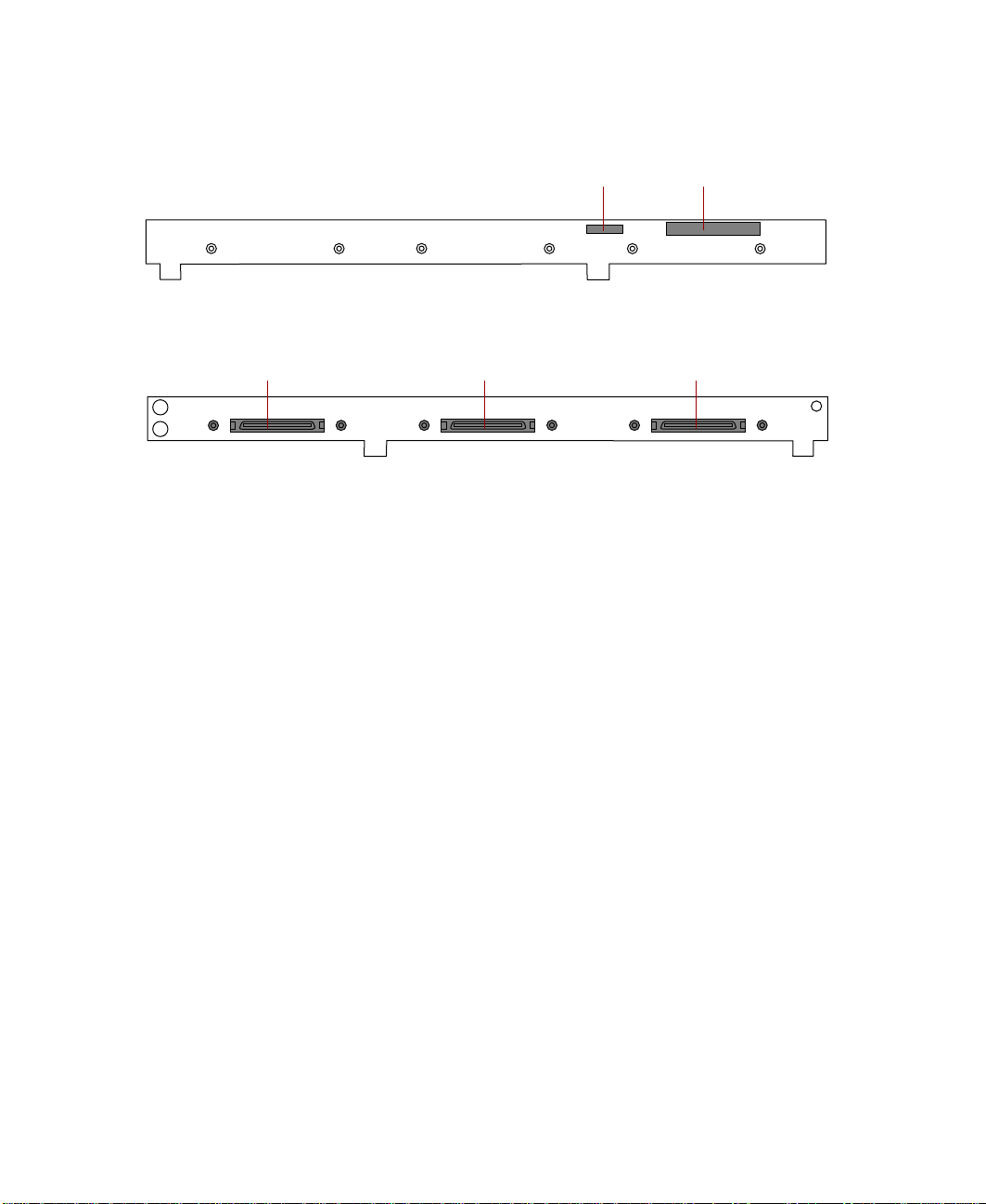
Hot-plug backplane
Back
Power connector Data connector
SCSI connector
SCSI ID 0
Front
Power connector connects t he power cable from the power supply.
Data connector connects the SCSI cable from the RAID controller.
SCSI drive connectors (3) connect the three SCA SCSI drives. Install drives
in increasing order of SCSI ID.
SCSI connector
SCSI ID 1
SCSI connector
SCSI ID 2
8 Gateway 7450R Server System Manual
Page 17

Control panel board
LAN1 LED LAN2 LED
System fault LED
Power LED
Fault LED reset button
Power button
Blower fault LED
Fan fault LED
USB port
USB connector
System fault LED glows amber when a hardware or system failure occurs.
Pressing the fault LED reset button turns this LED off, but does not correct
the fault.
Power LED glows green when the serve r has power and flashes green when
the server is in power saving mode. This LED glows amber when AC power
to the server is on, but the internal (DC) power is off which means there is
power to the server but the server is powered down.
Fault LED reset button resets any of the fault LEDs to its original state. This
button does not correct or clear the fault. If the fault condition persists, the
appropriate LED will turn on again until the fault is corre cted.
Power button turns the ser ver on and off.
LAN1 LED blinks green when there is traffic on the LAN1 connector. Glows
amber when the LAN1 connector experiences an interruption in connectivity.
LAN2 LED blinks green when there is traffic on the LAN2 connector. Glows
amber when the LAN2 connector experiences an interruption in connectivity.
Blower fault LED glows amber when one of the blowers has failed or entered
an out-of-tolerance sta te.
Fan fault LED glows amber when one of the fans has failed or entered an
out-of-toleran ce state.
Front panel connector
USB port provides front panel access for USB peripherals.
System Features 9
Page 18
USB connector connects the control panel to the system board.
Front panel connector connects the controls on the front panel with the
system board.
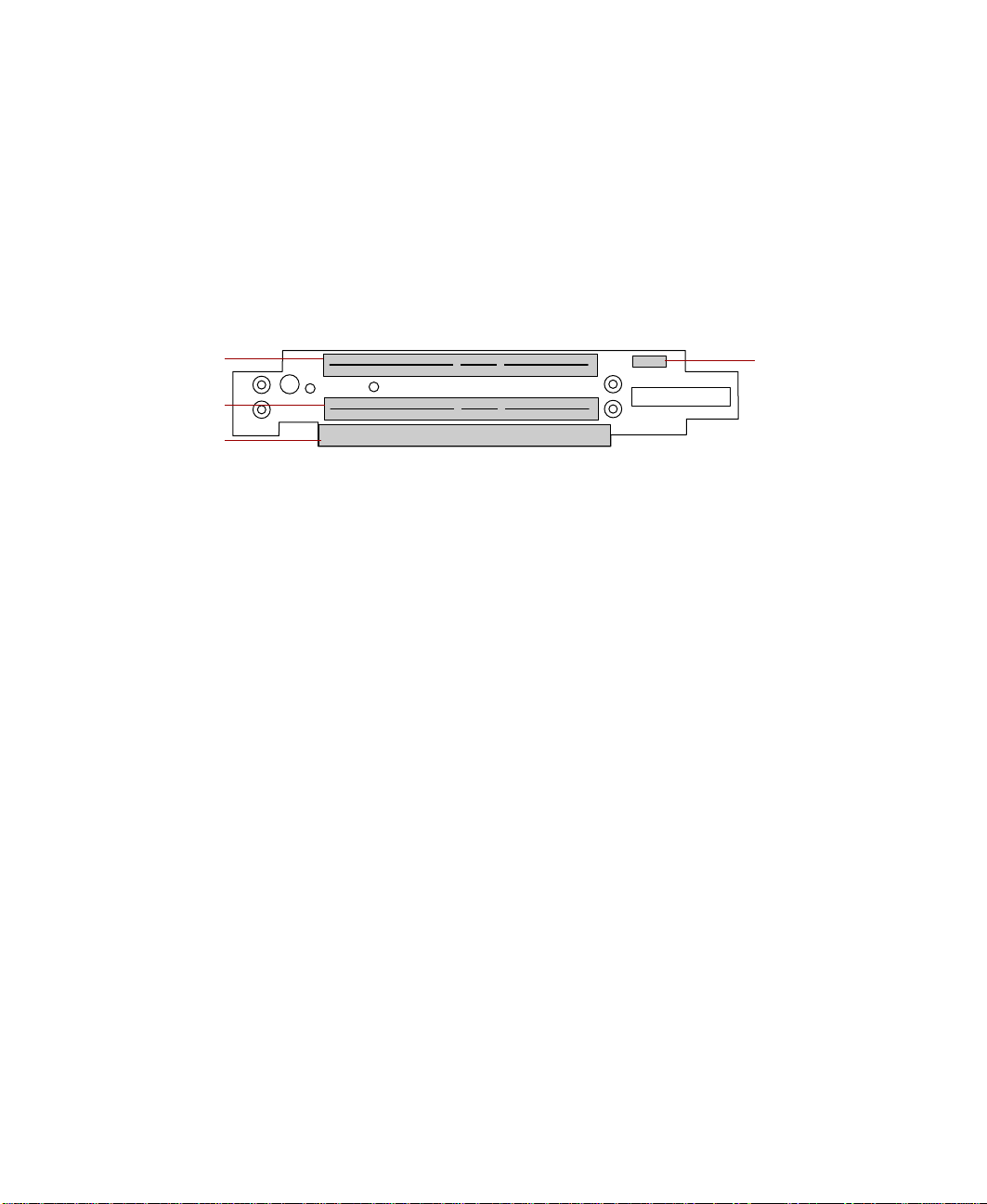
Riser card
The riser card includes a PCI bridge to support the two PCI expansion slots
through the edge connector on the system board.
PCI Slot 2
PCI Slot 1
System board
connector
PCI expansion slots provide support for as many as two 64-bit, 66 MHz PCI
expansion cards. Slot 1 is the lower slot and slot 2 is the upper slot.
System board connector connects to the system board.
Chassis intrusi o n switch sends a signal to the system management software
when the chassis cover is removed.
Chassis
intrusion
switch
10 Gateway 7450R Server System Manual
Page 19

System Setup
Setting up the server
Use the instructions in the Gateway 7450R Rackmount Installation Guide that
came with the server to assemble the server.
You should prepare a safe working environment before assembling the server
by following these guidelines:
Important Keep the boxes and packing material. If you n eed to s en d
the server to Gateway for repairs, you must use the original
packaging or your wa rranty may be voided .
■ Obtain an adequately rated uninterruptible power supply (UPS). A UPS
protects against AC line spikes, power interruptions, and other power
fluctuations that may damage the server.
■ Protect the server from extreme temperature and h umidity. Do not
expose it to direct sunlight, he ater ducts, or other he at-generating objects.
■ Route external cables carefully to make sure they do not block air vents
or impede airflow.
2
■ Make sure that the inlet air temperature within the rack cabinet remains
below the specified limit of 40
■ Keep the server away from equipment tha t generates magnetic fields,
such as unshielded stereo speakers. Even a telephone placed too close to
the server may cause interference.
° C (104° F).
System Setup 11
Page 20
■ Plug the server into a wall outlet, power strip, or uninterruptible power
supply (UPS).
Warning For the power supply of this equipment, an approved
power cor d ha s to be used . F or a rat ed c urr en t up to 6 A
and an equipment weight up to 6 kg, a power cord not
lighter than H05VV-F, 3 G, 0.75 mm
Warning Zum Net zanschluß dieses Gerätes ist eine geprüfte
Leitung zu verwenden. Für einen Nennstrom bis 6 A und
einem Gerätewicht größer 6 kg ist eine Leitung nicht
leichter als H05VV-F, 3 G, 0.75 mm
Starting the server
Before you start the server for the first time, make sure:
■ The power supply is autosensing and it automatically determines the
voltage of the incoming power source.
■ All cables are firmly connected to the proper ports on the back panel of
the server.
2
, has to be used.
2
einzusetz en.
Caution Electricity can flow from connected peripherals into the
system causing a shock. Make sure the server and
peripherals are turned off and unplugged from the power
outlet when you connect peripherals to the server.
■ The server and monitor are plugged into an AC outlet, power strip, or
UPS and that the power strip or UPS is turned on.
To start the system:
1 If you have connected the system components to a power strip or UPS,
make sure all the system components are turned off, then turn on the
power strip or UPS.
2 Turn o n th e m o ni t o r.
3 Turn on any other components c onnected to the server , such as speakers,
a printer, or a scanner.
12 Gateway 7450R Server System Manual
Page 21

Turn on the server. The power LED on the control panel is green when
4
the power is on. This same LED is amber when there is AC power
connected to the server, but the server is off.
If nothing happens when you turn on the system:
■ Make sure that the power cables are securely p lugged in and that
the power strip or UPS (if you are using one) is plugged in and
turned on.
■ Make sure the monitor is connected to the server, plugged into the
power strip, AC outlet, or UPS, and turned on. You may also need
to adjust the brightness and contrast controls on the monitor.
Understanding the Power-On Self-T est
When you turn on your server, a screen appears telling you to press F2 to
enter Setup or Esc to continue POST. The power-on self-test (POST) routine
checks the system memory and components. Press E
will begin in a few moments if you do not respond. Press the S
bypass the remaining memory count and shorten the startup process.
The system displays an error message if POST finds any problems. Write down
any error messages that you see. If you continue to have problems, these error
messages may help you or Gateway technical support diagnose the cause.
SC to start PO ST. POST
PACEBAR to
Setting up the operatin g system
The first time you start the server, the operating system takes a few minutes
to set up.
Refer to your operating system documentation for specific questions regarding
the operating system.
To complete the operating system setup in Windows NT:
1 After the server starts, the start-up wizard opens. Click Next.
2 Type the requested information in the appropriate text boxes. When you
have finished typing the information, click
3 Cont inue following the instructions and selecting options in the start-up
wizard dialog boxes, clicking
the wizard tells you to restart your server.
Next to move through the dialog boxes, until
Next.
System Setup 13
Page 22
If you need to return to the previous dialog box to change any of your
entries, click
Back.
4 Restart the server. The setup is complete.
Important For all operating systems, refer to the appropriate
operating system softwa re manual for sp ecific instr uctions.
T urning off the server
Every time you turn off the server, shut down the operating system first. You
may lose data if you do not follow the proper procedure.
To turn off the server in Windows NT:
1 Click Start, then select Shut down the computer?, then Shut Down.
2 Click OK. The operating system shuts down. When you see a message
It is now safe to turn off yo ur computer , turn off the server by pressing
saying
the power button.
By default, you must hold the power button in for four seconds to turn
the server off. BIOS Setup provides an option to set the power button to
turn the power off immediately when pressed.
3 Turn off the monitor and peripherals.
Caution When you turn the server off, some electric current still
flows through it. Before opening the server case or
connecting or removi ng any peripherals, turn of f the server ,
then unplug the power cord.
Important For other operating systems, such as Windows 2000 or
Novell Netware, refer to th e ap prop ria t e op era ting sy st em
software manual for specifi c inst ruct i ons. Some operating
systems will bypass the power button and turn the server
off under software control.
14 Gateway 7450R Server System Manual
Page 23

Resetting the server
If your server does not respond to keyboard or mouse input, you may have
to close programs that are not responding. If closing u nresponsive program s
does not restore your server to normal operation, you may have to perform
a forced shut down and restart the server.
To close unresponsive programs and shut down the server in
Windows NT:
1 Press CTRL+ALT+DEL. A window opens that lets you close a program that
is not responding.
2 Click Tas k M an a g er, then select the program that is not responding.
3 Close the program by clicking End Task.
4 If the server does not respond, press and hold the power button for four
seconds to force the server to shut down.
5 Turn the server back on.
As a part of the regular startup process, a program to check the disk status
runs automatically. When the checks are finished, Windows starts.
Important For other operating systems, such as Windows 2000 or
Novell Netware, refer to th e ap prop riate operating system
software m anual fo r specific i nstruct ions.
System Setup 15
Page 24

16 Gateway 7450R Server System Manual
Page 25

Case Access
3
Preventing static electricity discharge
Before opening the server case, follow th ese precautions to prevent damage
from static electricity. When opening your server case, always perform the
following procedure.
Caution Static electricity can permanently damage electronic
components in your server. Prevent electrostatic damage
to your server by following static electricity precautions
every time you open your server case.
To prevent static el ectricity discharg e:
1 Turn off the server power.
2 Touch a ba re metal surface on the back of the server.
3 Unplug all power cords from AC outlets and disconnect the modem cable
(if installed).
Also follow these static electricity precautions:
■ Avoid static-causing surfaces such as plastic and packing foam in your
work area.
■ Remove the parts from their antistatic bags or containers only when you
are ready to use them. Do not lay parts on the outside of an antistatic
bag or container because only the inside provides antistatic protection.
Case Access 17
Page 26
■ Always hold cards by their edges and their metal mounting brackets.
Avoid touching components on the cards and the edg e connectors that
connect to expansion slots. Never slide cards or other parts over any
surface.
Opening the case
Important All references to front, back, left, or ri ght on the server are
based on the se rve r be ing in a normal posi tio n, as v iew e d
from the front.
To remove or replace any of the rem ovable media drives or the internal
components you must open the case. Because the components inside the
server are extremely sensitive to static electricity, make sure you follow the
precautions at the beginning of this chapter to avoid static electricity damage.
Only qualified personnel should open the server for maintenance. If you are
qualified to maintain the server yourself, make sure you are properly grounded
before opening the case.
Caution Avoid exposure to dangerous electrical voltages and
moving parts by turning off the server and unplugging the
power cord and mod em cable (if inst alled) before removin g
the cover.
Removing the top panel
The top panel provides access to all of the internal components of the server.
Caution Operating the ser ver with the top panel remove d adversely
affects the therma l characteristics of the server interior and
can result in overheating of and possible damage to the
hard drives or the processors.
To remove the top panel:
1 Turn off the server and disconnect all power cords.
2 Observe all safety and static electricity precautions. See “Preventing static
electricity discharge” on page 17.
18 Gateway 7450R Server System Manual
Page 27
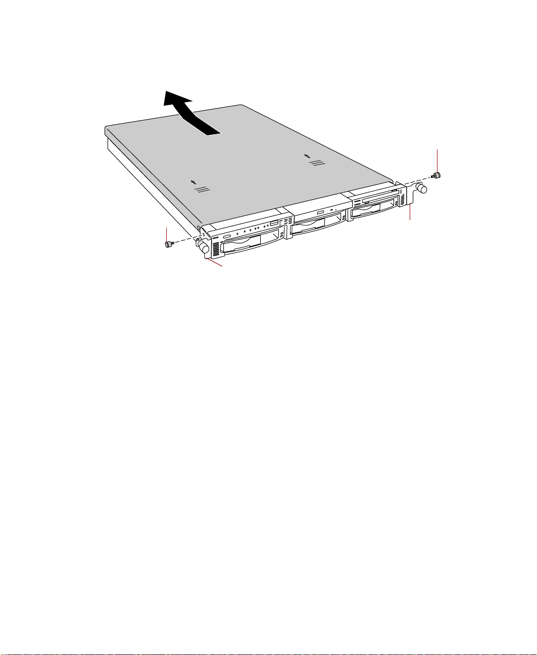
Remove the two thumbscrews from the top of the flanges at the sides of
3
the front panel.
Thumbscrew
H
S
U
P
H
US
P
Thumbscrew
Flange
4 Slide the top panel slightly to the back.
5 Lift the panel up and away from the chassis.
Flange
Case Access 19
Page 28

Closing the case
Close the case as soon as you finish installing or removing components so
that dust and dirt do not collect inside the server and to ma intain the thermal
characteristics of the server interior.
Caution Operating the ser ver with the top panel remove d adversely
affects the therma l characteristics of the server interior and
can result in overheating of and possible damage to the
hard drives or the processors.
Replacing the top panel
You must replace the top panel before you can o perate the server. If you do
not, a system intrusion event is logged by the system management hardware.
Be careful not to pinch any cables between the internal components and the
top panel as you replace it.
To replace the top panel:
1 Plac e the top panel on the top of the chassis approximately 3/4-inch back
from the front of the server.
2 Slide the panel toward the front of the chassis 3/4-inch, securing it in
place.
3 Replace the two thumbscrews you removed earlier.
20 Gateway 7450R Server System Manual
Page 29

Replacing and Adding Internal Devices
Drives
There are several types of drives and similar devices that can be installed in
the server.
Preparing to replace or add a drive
One diskette drive and at least one 1-inch high, 3.5-inch hot-plug hard drive
are included with the serv er. You can add an optional slimline CD d rive and
as many as two additional hot-plug drives for a total of three hot-plug drives.
As you prepare to install drives, keep the following in mind:
■ If you remove a drive, place it in an antistatic bag or container.
■ Before you install a drive, see the drive documentation for information
on configuring the drive, setting any jumpers on the drive, a nd attaching
cables to the drive.
■ If you are installing a drive that uses an add-in controller card, install
the card before you install the drive.
4
■ You may need to configure the drives you install using the BIOS Setup
utility or the SCSISelect utility. Press F2 at start up to open the BIOS Setup
utility or press C
TRL+A to enter the SCSISelect utility.
Replacing and Adding Internal Devices 21
Page 30

Drive cabling information
The system includes two different types of drive cables. Each drive cable is
clearly labeled, indicating the cable type and showing which end to connect
to the appropriate connector on the system board and which end to connect
to the drive.
■ Use the diskette drive cable to connect the diskette drive.
■ Use the SCSI LVD cable to connect the hot-plug backplane to the
integrated SCSI controller on the system board.
If you order the optional CD drive, a third cable is provided. Use the standard
IDE cable to connect the CD drive.
Replacing the diskette drive
The diskette drive is on the right side of the server. See “Interior of system”
on page 5 for the location of the diskette drive.
Important The replacement drive should include the bracket and
small circuit board. If it does not, transfer those
components to the new drive.
To replace the diskette drive assembly:
1 Turn off the system and disconnect the power cord and all other external
peripheral de vices.
2 Open the case. See “Opening the case” on page 18 and “Preventing static
electricity discharge” on page 17.
3 Remove the power and data cables from the small printed circuit board
at the back of the drive. Note their locations and orientations.
22 Gateway 7450R Server System Manual
Page 31
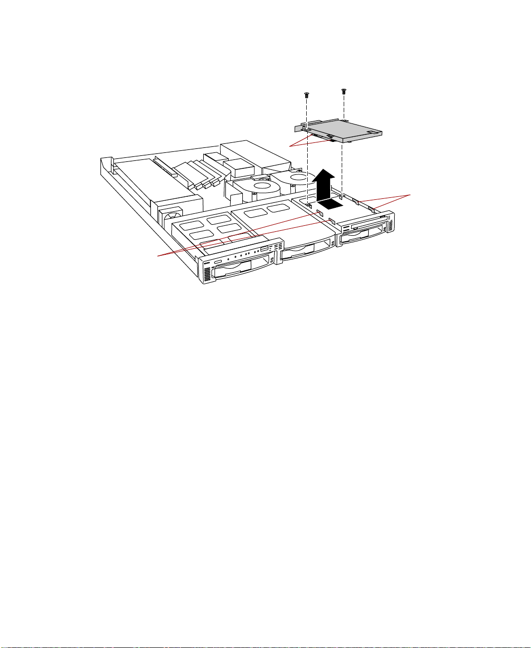
Remove the diskette drive assembly by removing the two screws near the
4
back of the drive.
Slots
Hooks
Hooks
5 Slide the drive assembly back slig htly to disengage the hooks on the drive
bay from the slots on the diskette drive bracket, then pull the drive
assembly out of the chassis.
6 If necessary , set any jumpers on the replacement drive assembly. (See your
drive documentation for proper drive jum per settings and cable
orientation.)
7 Replace the diskette drive assembly in the chassis. Make sure the hooks
extend through the slots on the new bracket, then slid e the diskette drive
assembly forward.
8 Secure the diskette drive assembly using the screws you removed in
Step 4.
9 Connect the power and data cables, making sure the cables are in their
original positions.
10 Close the case. See “Closing the case” on page 20.
11 Reconnect the power cord and all other external peripheral devices, then
turn on the computer.
Replacing and Adding Internal Devices 23
Page 32

Installing a CD drive
The CD drive bay is in the center of the front panel. If the server did not
include a CD drive, a blank or “dummy” unit occupies the bay and must be
removed.
Important The CD drive assembly should include the bracket and
small circuit board. If it does not, contact Client Care.
To install your CD drive assembly:
1 Turn off the system and disconnect the power cord and all other external
peripheral de vices.
2 Open the case. See “Opening the case” on page 18 and “Preventing static
electricity discharge” on page 17.
3 Remove the two screws that secure the “dummy” unit to the drive bay.
4 Slide the “dummy” unit back slightly to disengage the hooks on the drive
bay from the slots on the bracket, then pull the “dummy” unit out of
the chassis.
24 Gateway 7450R Server System Manual
“Dummy” unit
Page 33

If necessary, set any jumpers on the CD drive assembly. (See your drive
5
documentation for proper drive jumpe r settings and cable orientation.)
6 Place the CD drive assembly in the chassis. Make sure the hooks extend
through the slots on the bracket, then slide the CD drive assembly
forward.
7 Secure th e CD drive assembly with the two screws you removed in Step 4.
8 Connect the power and data cables, making sure the cables are in the
correct position and orientation.
The IDE cable ships with the CD drive kit. Make sure you route the cable
directly from the CD drive, through the cable clamp, and to the prim ary
IDE connector on the system board. Other routing may interfere with
internal airflow and the thermal characteristics of the server.
9 Close the case. See “Closing the case” on page 20.
10 R econnect the power cord and all other external peripheral devices, then
turn on the system.
Replacing the CD drive assembly
The CD drive assembly is located beside the diskette drive assembly in the
center of the front panel.
Important The replacement drive should include the bracket and
small circuit board. If it does not, transfer those
components to the new drive.
To replace the CD drive assembly:
1 Turn off the system and disconnect the power cord and all other external
peripheral de vices.
2 Open the case. See “Opening the case” on page 18 and “Preventing static
electricity discharge” on page 17.
3 Remove the power and data cables from the small printed circuit board
at the back of the drive. Note their locations and orientations.
Replacing and Adding Internal Devices 25
Page 34

4 Remove the two screws that secure the CD drive assembly to the chassis.
Slots
Hooks
Hooks
5 Slide the drive assembly back slig htly to disengage the hooks on the drive
bay from the slots on the CD drive bracket, then pull the drive assembly
out of the chassis.
6 If necessary, set any jumpers on the replacement drive. (See your drive
documentation for proper drive jumpe r settings and cable orientation.)
7 Place the new CD drive and brac ket i n t he chas sis . Ma ke su re t he h oo ks
extend through the slots on the new bracket, then slide the CD drive
forward.
8 Secure the CD drive with the two screws you removed in Step 4.
9 Connect the power and data cables, making sure the cables are in their
original positions.
10 Close the case. See “Closing the case” on page 20.
11 Reconnect the power cord and all other external peripheral devices, then
turn on the system.
26 Gateway 7450R Server System Manual
Page 35

Replacing a hot-plug drive
The hot-plug drives are located along the bottom edge of the front panel as
you face the system. The hot-plug bay sup ports as many as three 1-in ch high ,
3.5-inch SCSI hard drives.
The hot-plug drives are assigned SCSI ID numbers by the hot-plug backplane
with the drive on the left end of the hot-plug bay assigned SCSI ID 0. The
backplane assigns SCSI IDs to the other drives in order up to SCSI ID 2 at the
right end of the hot-plug bay. See “Hot-plug backplane” on page 8 for the
locations of the drives by SCSI ID number.
Important Gateway tests and verifie s the operatio n and compati bility
of the drives we sell. Addit ional or replacement drive s must
conform to Gateway standards, especially in a RAID or
mission-critical environment.
Install the first drive in the left bay, then install drives in increasing order by
SCSI ID number thereafter.
To replace a failed drive:
1 Before you remove the failed drive, use the appropriate software and
utilities installed on the system to stop all activity on the SCSI bus.
Instructions for using the software are provided by the software
manufacturer.
2 Use the utilities or look at the drive indicator LEDs on the front panel
to determine which drive needs to be replaced.
Replacing and Adding Internal Devices 27
Page 36

3 Remove the drive from the drive bay by unclipping the retention lever
and rotating the lever out away from the front of the system.
Retention lever
4 Continue pulling outward until the drive is entirely out of the system.
5 Remove the six screws that secure the drive to the carrier.
6 Remove the drive from the carrier.
28 Gateway 7450R Server System Manual
Page 37

Install the new drive in the carrier using the six screws you rem oved in
7
Step 5. Make sure the drive is oriented correctly.
8 Align the drive carrier with the slots at the sides of the drive bay. Leave
the retention lever in the open position.
9 Push the drive all of the way into the drive bay until the connector at
the back joins with the corresponding connector on the SCSI backplane,
then firmly close the lever.
10 R un any necessary utilities to setup the new drive. See the utility software
documentation for details.
Adding a hot-plug drive
The hot-plug drives are located along the bottom edge of the front panel as
you face the system. The hot-plug bay supports as many as three 1-inch high
3.5-inch SCSI hard drives.
Replacing and Adding Internal Devices 29
Page 38

The hot-plug drives are assigned SCSI ID numbers by the hot-plug backplane
with the drive on the left end of the hot-plug bay assigned SCSI ID 0. The
backplane assigns SCSI ID s to the other drives in orde r up to SCSI ID 2 on
the right end of the hot-plug bay. See “Hot-plug backplane” on page 8 for the
locations of the drives by SCSI ID number.
Important Gateway tests and verifie s the operatio n and compati bility
of the drives we sell. Addit ional or replacement drive s must
conform to Gateway standards, especially in a RAID or
mission-critical environment.
Install the first drive in the left bay, then install drives in increasing order by
SCSI ID number thereafter (left to right).
To install an additional hot-plug drive:
1 Remove the drive carrier from the drive bay by unclipping the retention
lever and rotating the lever out away from the front of the system.
Retention lever
2 Continue pulling outward until the drive carrier is entirely out of the
system.
3 Usi ng six screws from the accessory kit, install the new drive in the carrier.
Make sure the drive is oriented correctly.
30 Gateway 7450R Server System Manual
Page 39

Align the drive carrier with the slots at the sides of the drive bay. Leave
4
the retention lever in the open position.
5 Push the drive all of the way into the drive bay until the connector at
the back joins with the corresponding connector on the SCSI backplane,
then firmly close the lever.
6 Run any necessary utilities to setup the new drive. See the utility software
documentation for details.
Memory
Four DIMM sockets on the system board support up to 4.0 Gigabytes (GB) of
PC/133 SDRAM.
The DRAM DIMMs supported by the system board conform to the fo llowing
standards:
■ 128 MB, 256 MB, 512 MB, and 1024 MB ECC DIMMs
■ PC/133-compliant, registered, ECC SDRAM
■ 128 MB minimum system memory
■ 4.0 GB maximum system memory
When you select and install DIMMs, keep the following in mind:
■ Do not use unbuffered DIMMs.
■ Memory should be added in order, from DIMM 1 to DIMM 4.
■ There can be no empty slots between installed DIMMs.
■ No jumper settings are required for the memory size or type because the
BIOS automatically detects this information.
Important Gateway recommends that you purchase memory
upgrades through Gateway sales. An incorrect memory
match may adversely af fe ct the per formanc e of the s erver.
Replacing and Adding Internal Devices 31
Page 40

Replacing memory
To replace DIMMs:
1 Turn off the system and disconnect the power cord and all other external
peripheral de vices.
2 Open the case. See “Opening the case” on page 18 and “Preventing static
electricity discharge” on page 17.
3 Pull open the socket clamps on each side of the DIMM socket, then lift
the DIMM out of the socket. Store the DIMM in an anti-static container.
2
1
DIMM 1
1
DIMM 4
4 Insert the new DIMM into the socket, aligning the two notches in the
DIMM with the two notches in the DIMM socket.
5 Gently press th e DIMM into the socket until it is firmly sea ted. Inserting
the DIMM automatically locks the socket clamps on each end of the
DIMM.
6 Close the case. See “Closing the case ” on page 20.
7 Reconnect the peripherals and the power cord, then turn on the system .
32 Gateway 7450R Server System Manual
Page 41

Adding memory
To add DIMMs:
1 Turn off the system and disconnect the power cord and all other external
peripheral de vices.
2 Open the case. See “Opening the case” on page 18 and “Preventing static
electricity discharge” on page 17.
3 Pull open the socket clamps on each side of the DIMM socket.
4 Insert the new DIMM into the socket, aligning the two notches in the
DIMM with the two notches in the DIMM socket.
DIMM 1
DIMM 4
5 Gently press th e DIMM into the socket until it is firmly sea ted. Inserting
the DIMM automatically locks the socket clamps on each end of the
DIMM.
6 Close the case. See “Closing the case” on page 20.
7 Reconnect the peripherals and the power cord, then turn on the system .
Replacing and Adding Internal Devices 33
Page 42

Processors
The system is compatible with the Intel® Pentium® III 866 MHz and faster
processors with 133 MHz front-side bus (FS B). As many as two processors may
be installed in the system. You do not need to install additional voltage
regulator modules (VRMs), because the VRMs for both p rocessors are built into
the system board.
The server uses different heat sinks for the primary and secondary processors.
When ordering a replacement or upgrade processor, make sure that you order
the correct processor kit for the processor you are installing. The primary
processor, located closer to the front of the server, uses a smaller heatsink.
The secondary processor, located closer t o the ba ck of the server, uses a larger
heatsink.
Replacing the primary processor
When replacing a processor, order a processor upgrade from The Accessor y
Store on the Gateway Web site.
Caution A heatsink must be instal led on each processor. Installing
a processor without a heatsink could result in damage to,
or failure of, the processor.
To replace the primary processor:
1 Turn off the system and disconnect the power cord and all other external
peripheral de vices.
2 Open the case. See “Opening the case” on page 18 and “Preventing static
electricity discharge” on page 17.
3 Locate the primary processor, see “System board” on page 6 for the
location of the system board components.
34 Gateway 7450R Server System Manual
Page 43

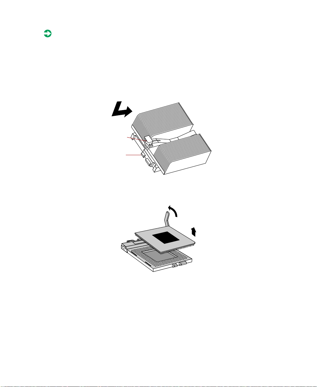
Unclip the heatsink by pressing down on the top of the clip, th en pushing
4
the top of the clip toward the heatsink.
Clip
Hook
5 Lift the heatsink off of the processor.
6 Remove the processor by pulling the lever arm slightly away from the
processor socket, then lifting it to a ninety-degree angle.
1
2
7 Lift the old processor out of the socket.
8 Insert the new processor by aligning pin one on the processor and the
socket, then place the processor into the socket.
2
Pin 1
Replacing and Adding Internal Devices 35
1
Page 44

9 Secure the new processor by pushing the lever arm all of the way down
until it clicks into place.
10 Replace the heatsink.
11 Place the fixed end of the heatsink clip over the hook on the processor
socket first, then press the hinged end of the clip over the hook on the
other side of the processor socket.
12 Close the case. See “Closing the case” on page 20.
13 Reconnect the power cord and all other cords you removed, then turn
on the system.
Replacing the secondary processor
When replacing a processor, order a processor upgrade from The Accessor y
Store on the Gateway Web site.
Caution The correct heatsin k must b e ins talled on each processo r.
Installing a processor without a heatsink could result in
damage to, or failure of, the processor. Make sure you
order the correct processor upgrade kit.
36 Gateway 7450R Server System Manual
Page 45
To replace the secondary processor:
1 Turn off the system and disconnect the power cord and all external
peripheral de vices.
2 Open the case. See “Opening the case” on page 18 and “Preventing static
electricity discharge” on page 17.
3 Un clip the heatsink by pressing down on the top of the clip, then pushing
the top of the clip toward the heatsink.
Clip
Hook
4 Remove the processor by pulling the lever arm slightly away from the
processor socket, then lifting it to a ninety-degree angle.
1
5 Lift the old processor out of the socket.
Replacing and Adding Internal Devices 37
2
Page 46

6 Insert the new processor by aligning pin one on the processor and the
socket, then place the processor into the socket.
1
Pin 1
2
7 Secure the new processor by pushing the lever arm all of the way down
until it clicks into place.
8 Replace the heatsink. Make sure that the heatsink is oriented properly
over the processor and socket.
9 Close the case. See “Closing the case ” on page 20.
10 Reconnect the power cord and all other cords you removed, then turn
on the system.
38 Gateway 7450R Server System Manual
Page 47

Adding a secondary processor
The system is compatible with the Intel® Pentium® III 866 MHz and faster
processors with 133 MHz front-side bus (FSB). As many as two processors may
be installed in the system. The second processor must match the first processor
in speed or the system functions at the speed of the slowest processor.
When adding a second processor order a proc essor upgrade kit from The
Accessory Store on the Gateway Web site.
Caution The correct heatsin k must b e ins talled on each processo r.
Installing a processor without a heatsink could result in
damage to, or failure of, the processor. Make sure you
order the correct processor upgrade kit.
To add a second processor:
1 Turn off the system and disconnect the power cord and all external
peripheral de vices.
2 Open the case. See “Opening the case” on page 18 and “Preventing static
electricity discharge” on page 17.
3 Open the lever on the secondary processor socket.
4 Align the new processor with the processor slot. Note that the processor
slot is keyed so the processor can only be installed one way.
2
Pin 1
1
5 Place the processor in the socket, then close the lever to secure the
processor.
Replacing and Adding Internal Devices 39
Page 48

6 Place the secondary (large) heatsink ov er the processor and socket,
making sure that it is oriented properly.
7 Place the fixed end of the clip over the hook on the back of the socket,
then press the hinged end of the clip over the hook o n the front o f the
socket.
8 Close the case. (See “Closing the case” on page 20.)
9 Reconnect the power cord and all other cords you removed, then turn
on the system.
Replacing the battery
The battery provides power for the system real-time clock and CMOS memory ,
which holds the system configuration information.
If your battery is failing you may notice the server clock slowing down and
giving you the incorrect time.
40 Gateway 7450R Server System Manual
Page 49

Open the BIOS Setup utility and write down all the values in the various
menus before replacing the battery . Replacing the battery resets the BIOS Setup
utility to its default values.
Warning Danger of explosion if battery is incorrectly replaced.
Replace only with the same or equivalent type
recommended by manufacturer.
Dispose of used batteries according to manufacturer’s
instructions.
Warnung Explosionsgefahr bel falsch eingebautter batterie.
Ersetzen der batterien nur mit batterien des gleichen typs
oder mit batterien vom hersteller empfohlenen typs.
Entsorgen gebrauchter batterien entsprechned
herstellerangaben.
Attention Il y a danger d’explosion s’il y a replacement incorrect de
la batteri e.
Remplacer uniquement avec une batterie du même type
ou d’un type équivalent reco mmandé par le constructeur.
Mettre au rebut les batteries usagées conformément aux
instructions du fabricant.
To replace the battery:
1 Restart the server and start the BIOS Setup utility.
2 Write down the CMOS values from each tab in the BIOS Setup utility so
you can reenter them after you replace the battery. For more information,
see “About the BIOS Setup utility” on page 61.
3 Turn off the server, disconnect the power cord and all external peripheral
devices.
4 Open the case. See “Opening the case” on page 18 and “Preventing static
electricity discharge” on page 17.
5 Locate the battery on the system board (see “System board” on page 6).
The battery is circular and has the positive pole mark (+) on the top.
Replacing and Adding Internal Devices 41
Page 50

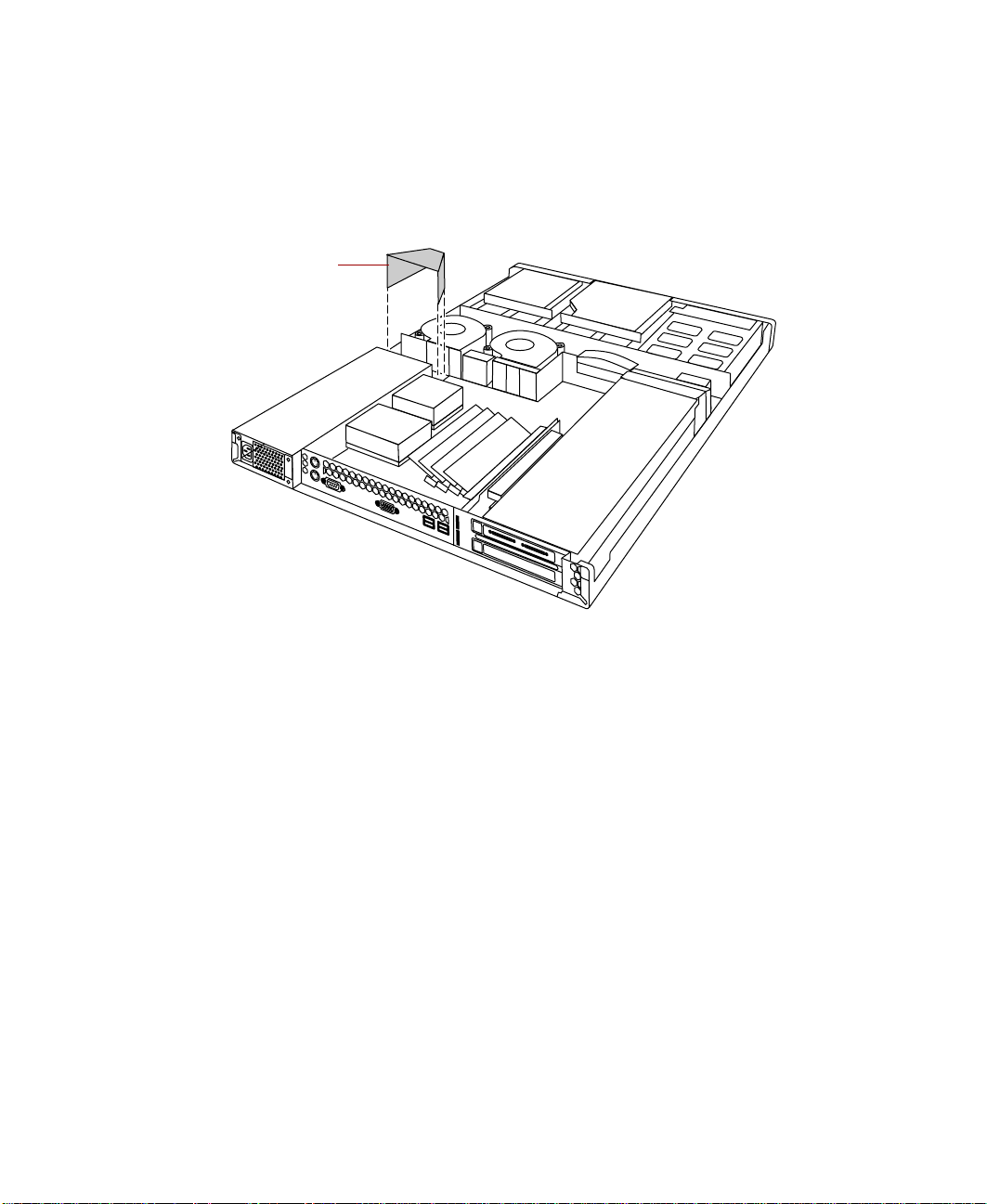
6 Remove the cable over the air baffle and pull the air baffle out of the
server.
Air baffle
7 Using your finger or a small, flat-bladed screwdriver, carefully press the
small spring clip to remove the battery from its socket on the system
board.
Spring clip
8 Press the new battery in the socket with the positive pole up. Be sure you
have pressed the battery down far enough for it to contact the base of
the socket (it should snap into place).
9 Close the case. See “Closing the case ” on page 20.
10 Reconnect the peripherals and the power cord, then turn on the system.
11 If the CMOS data is not correct, change the information in the BIOS Setup
utility using the data you recorded in Step 2.
42 Gateway 7450R Server System Manual
Page 51

Expansion cards
The server has two expansion slots on the riser card that can be used for a
variety of expansion cards. These slots support 64-bit, 66 MHz PCI cards. Both
slots will hold full-length, full-height cards.
Replacing an expansion card
You must install an expansion card in slot 1 before you can install an
expansio n card in slo t 2.
To replace an expansion card:
1 Set any jumpers and switches on the replacement card, if required in the
card instructions.
2 Turn off the server, then disconnect the power cord and all ex ternal
peripheral de vices.
3 Open the case. See “Opening the case” on page 18 and “Preventing static
electricity discharge” on page 17.
4 Disconnect any cables attached to the o ld card.
5 Remove the screw that holds the expansion card bracket in place.
Expansion card brack et
Expansion cardScrew
Replacing and Adding Internal Devices 43
Page 52

6 Remove the card holder from the other end of the expansion card.
Card holder
7 Remove the old expansion card from the slot.
8 Set any jumpers or switches on the new expansion card, then install the
new expansion card in the empty slot.
44 Gateway 7450R Server System Manual
Page 53

If the card is full-length, insert the card extension into the card guide.
9
The card extension in slot 1 fits below the card guide and the card
extension in slot 2 fits into the groove in the card guide.
Card guide
Card exten sions
10 Replace the card holder over the card guide and the end of the expansion
card. See the illustration following Step 6.
11 Replace the screw in the expansion card bra cket to secure the ca rd. See
the illustration following Step 5.
12 Connect any cables to the card. See the card documentation for the
proper cable orientation.
13 Close the case. See “Closing the case” on page 20.
14 Reconnect the peripherals and the power cord, then turn on the system.
Y ou may need to reconfigure the server after replacing an expansion card. You
may also need to install upgrade software that came with the card. Check the
card documentation for additional information.
Adding an expansion card
When adding an expansion card, you must install an expansion card in s lot 1
before you can install an expansion card in slot 2.
Replacing and Adding Internal Devices 45
Page 54

To add an expansion card:
E
1 Set any jumpers and switches on the card, if required in the card
instructions.
2 Turn off the server, disconnect the power cord and all external peripheral
devices.
3 Open the case. See “Opening the case” on page 18 and “Preventing static
electricity discharge” on page 17.
4 Locate an available slot and remove the slot cover by removing the screw
on the expansion card bracket, then remove the slot cover.
xpansion card bracket
Slot coverScrew
46 Gateway 7450R Server System Manual
Page 55

Remove the card holder from the other end of the exp ansion card.
5
Card holder
6 Set any jumpers or switches on the expansion card, then install the
expansion card in the empty slot.
7 If the card is full-length, insert the card extension into the card guide.
The card extension in slot 1 fits below the card guide and the card
extension in slot 2 fits into the groove in the card guide.
Card guide
Card exten sions
Replacing and Adding Internal Devices 47
Page 56

8 Replace the card holder over the card guide and the end of the expansion
E
card.
9 Replace the screw in the expansion card br acket to secure the card.
xpansion card bracket
Expansion cardScrew
10 Connect any cables to the card. See the card documentation for the
proper cable orientation.
11 Close the case. See “Closin g the case” on pa ge 20.
12 Reconnect the peripherals and the power cord, then turn on the system.
Y ou may need to reconfigure the server after installing some expansion cards.
Y ou ma y also need to install softwa re that came with the card. Check the card
documentation for additional information.
Replacing the power supply
The 200-W power s upply provides all s ystem power.
To replace the power supply:
1 Turn off the system and disconnect the power cord and all periph erals.
2 Open the case. See “Opening the case” on page 18 and “Preventing static
electricity discharge” on page 17.
48 Gateway 7450R Server System Manual
Page 57
Disconnect the cables from the power supply to all other internal parts.
3
Note their positions and orientations so y ou can connect the c ables from
the new power supply.
4 Remove the air duct between the power supply and the number two
blower.
Air duct
Replacing and Adding Internal Devices 49
Page 58

5 Remove the three screws that secure the power supply to the back panel,
then slide the power supply toward the front of the server to free it from
the pin on the bottom of the server and lift it out of the ch assis.
Pin
6 Place the new power supply in the chassis making sure the pin on the
bottom of the chassis passes through the hole on the power supply
bracket.
7 Replace the screws you removed in Step 5 above.
8 Reconnect the cables you removed in St ep 3.
9 Replace the air duct you removed in St ep 4.
10 Close the case. See “Closing the case” on page 20.
11 Reconnect the power cord and all external peripherals, then turn on the
system.
Replacing a blower
The blowers are located between the hot-plug backplane and the system
board.
50 Gateway 7450R Server System Manual
Page 59

To replace a blower:
1 Use the system management software to determine which blower has
failed.
2 Turn off the system and disconnect the power cord and extern al
peripherals.
3 Open the case. See “Opening the case” on page 18 and “Preventing static
electricity discharge” on page 17.
4 Unplug the correct blower cable from the system board and remove the
cable from the cable cl amps.
5 Lift the blower off of the pins on the bottom of the chassis.
Blower 2
Blower 1
6 Insert the new blower onto the pins on the bottom of the chassis.
7 Insert the blower cable into the cable clamps. Make sure it does not get
pinched in the cover or block airflow.
8 Plug the blower cable into the connector on the system board. See
“System board” on page 6 for the locations of the blower connectors.
9 Close the case. See “Closing the case” on page 20.
10 Reconnect the power cord and external peripherals, then turn on the
system.
Replacing and Adding Internal Devices 51
Page 60
Replacing a fan
Fan 1 is located between the expansion cards and the drive bays and fan 2
is located between the two blowers. See “Interior of system” on page 5 for the
locations of the fans.
To replace a fan:
1 Use the system management software to determine which fan has failed.
2 Turn off the system and disconnect the power cord and extern al
peripherals.
3 Open the case. See “Opening the case” on page 18 and “Preventing static
electricity discharge” on page 17.
4 Unplug the fan cable from the system board and remove the cable from
the cable clamps .
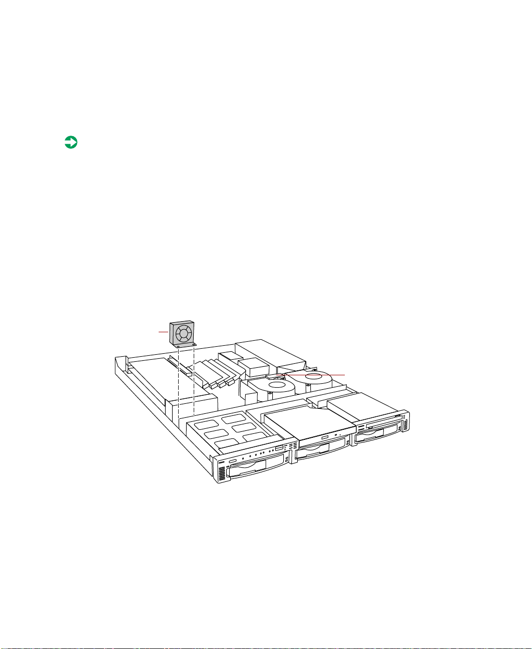
5 Lift the fan out of the fan bracket. (The fan bracket is not secured to the
chassis and may come out when you remove the fan. Replace it on the
pins on the bottom of the chassis.)
Fan 1
6 Insert the new fan into the fan bracket. Make sure the direction of
rotation and airflow match the direction and airflow of the fan you
removed.
52 Gateway 7450R Server System Manual
Fan 2
Page 61
Plug the fan connector into the connector on the system board and
7
replace the cable in the cable clamps. Make sure the cable does not
interfere with airflow and will not be pinched when you close the cover.
8 Close the case. See “Closing the case” on page 20.
9 Reconnect the power cord and external peripherals, then turn on the
system.
Replacing the control panel board
The control panel board is mounted on the front of the chassis, inside the
front panel.
To replace the control panel board:
1 Turn off the system and disconnect the power cord and all external
peripherals.
2 Open the case. See “Opening the case” on page 18 and “Preventing static
electricity discharge” on page 17.
3 Disconnect all c ables from the control panel board. Note the location and
orientation of each cable as you remove it.
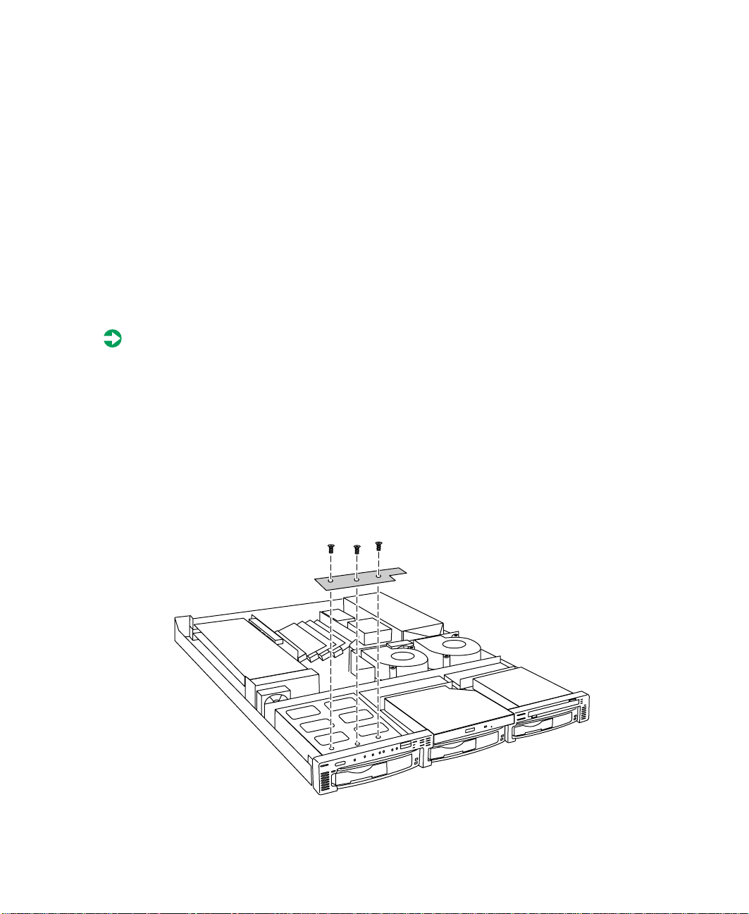
4 Remove the three screws that secure the control panel board to the front
of the chassis, then remove the board from the server.
Replacing and Adding Internal Devices 53
Page 62

5 Install the new c ontrol pa nel board by replac ing the th ree screws you
removed in Step 4.
6 Plu g the front panel cables into the appropriate connectors on the control
panel board.
7 Close the case. See “Closing the case ” on page 20.
8 Reconnect the p ower cord and the external peripherals, then turn on the
system.
Replacing the hot-plug backplane
The three drive hot-plug backplane is at the back of the hot-plug drive cage.
The backplane supports as many as three hot-swappable Ultra3 SCSI drives.
To replace the hot-plug backplane assembly:
1 Turn off the system and disconnect the power cord and all external
peripheral de vices.
2 Open the case. See “Opening the case” on page 18 and “Preventing static
electricity discharge” on page 17.
3 Disc onnect all cables to the hot-plug backplane. Note their locations and
orientations.
4 Remove all hot-plug drives. Be careful to note which drive was in which
slot.
54 Gateway 7450R Server System Manual
Page 63

Remove the four screws that secure the hot-plug backplane assembly in
5
the chassis, then lift the assembly out of the server.
6 Place the new backplane assembly in the chassis and secure it using the
four screws you removed in Step 5.
7 Reconnect all cables on the backplane to the correct connectors.
8 Replace all ho t-plug drives. Make sure that you replace them in the same
slots that they were in before you removed them.
9 Close the case. See “Closing the case” on page 20.
10 Reconnect all peripherals and the power cord, then turn on the system.
Replacing the riser card
The riser card connects to the edge connector on the left side of the system
board and provides connectors for as many as two full-height, full-length
expansio n cards.
Replacing and Adding Internal Devices 55
Page 64

To replace the riser card:
1 Turn off the system and disconnect the power cord and all external
peripheral de vices.
2 Open the case. See “Opening the case” on page 18 and “Preventing static
electricity discharge” on page 17.
3 Remove any expansion cards installed in the system. See “Replacing an
expansion card” on page 43.
4 Remove the two screws that secure the riser card assembly to the chassis.
5 Disconnect the riser card from the edge connector on the system board,
then lift the riser card assembly out of the chassis.
56 Gateway 7450R Server System Manual
Page 65
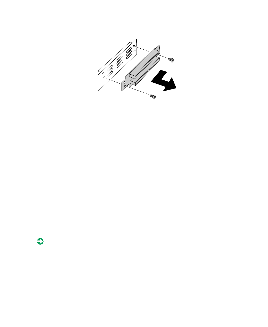
Remove the two screws that secure the riser card to the bracket.
6
7 Slide the riser card to the left on the bracket to free it from the pins on
the bracket, then pull the riser card off of the bracket.
8 Place the new riser card on the bracket and secure it with the two screws
you removed in Step 6.
9 Insert the new riser card assembly into the chassis and insert the system
board edge connector into the connector on the back of the riser card.
10 Secure the riser card with the four screws you removed in Step 4.
11 Replace any expansi on cards you removed in St ep 3.
12 Close the case. See “Closing the case” on page 20.
13 Reconnect all peripherals and the power cord, then turn on the system.
Replacing the system board
The system board integrates the other elements of the system, such as the
processor, memory, storage, networking, and communications.
To replace the system board:
1 Turn off the system and disconnect the power cord and all external
peripheral de vices.
2 Open the case. See “Opening the case” on page 18 and “Preventing static
electricity discharge” on page 17.
Replacing and Adding Internal Devices 57
Page 66

3 Remove all expansion cards from the system. See “Replacing an
expansion card” on page 43.
4 Remove the two screws that secure the riser card assembly to the chassis.
5 Disconnect the riser card from the edge connector on the system board,
then lift the riser card assembly out of the chassis.
6 Disconnect all cables from the system board. Note the locations and
orientations of the cables as you remove them.
7 Remove any processors and DIMMs that you will install in the new
system board. See “Replacing memory” on page 32, “Replacing the
primary processor” on page 34, and “Replacing the secondary processor”
on page 36.
58 Gateway 7450R Server System Manual
Page 67

Remove the eight screws that secure the system board to the chassis, then
8
lift the system board out of the chassis.
9 Remove the new syst em board from its anti-static bag and set any jumpers
that you may need to set for your configuration. See “System board” on
page 6 and “Setting the system board jumpers and switches” on page 64.
10 Place the new system board in the chassis.
11 Replace the eight screws you removed in Step 8.
12 Install the DIMM(s) and processor(s) in the new system board. See
“Replacing memory” on page 32, “Replacing the primary processor” on
page 34, and “Replacing the secondary processor” on page 36.
13 Reconnect the system cables to the appropriate connectors on the system
board. See “System board” on page 6 for reference.
14 R eplace the riser card using the two screws you removed in Step 4. Make
sure you seat the riser card connector securely onto the edge connector
on the system board.
Replacing and Adding Internal Devices 59
Page 68

15 R epla ce an y expa nsio n card s you rem oved fr om th e sys tem in Step3. See
“Replacing an expa nsion card” on page 43.
16 Close the case. See “Closing the case” on page 20.
17 Reconnect all peripherals and the power cord, then turn on the system.
60 Gateway 7450R Server System Manual
Page 69

Using the BIOS Setup Utility
About the BIOS Setup utility
The server BIOS has a built-in setup utility that lets you configure several basic
system characteristics. The settings are stored in battery-backed RAM and are
retained even when the power is off.
Enter the BIOS Setup utility by restarting the server, then pressing F2 when
prompted during the startup process. The Main BIOS Setup utility screen
opens. It may not look exactly like the screen shown below.
BIOS Setup Utility
Main Advanced Security Power Boot Exit
Item Specific Help
BIOS Version
System Time:
System Date:
Legacy Diskette A:
3A00
[xx:xx:xx]
[xx/xx/xxxx]
[ ]
[TAB] , [Sh ift-Tab], or
[Enter] selects field.
5
>Primary Master:
>Primary Slave:
>Secondary Master:
>Secondary Slave:
System Memory:
F1 Help
ESC Exit ←→ Select Menu ENTER Select > Sub-Menu F10 Save & Exit
↑↓ Select Item -/+ Change Values F9 Setup Defaults
[CD-ROM]
[None]
[None]
[None]
256 MB
Using the BIOS Setup Utility 61
Page 70

As you select items on the Main menu or in submenus, you see specific
information related to the current selection in the Item Specific Help box.
The command bar shows the keystrokes necessary to access help, navigate
through the menus, and perform other functions.
■ F1 opens the Help screen, providing general help for using the BIOS Setup
utility.
■ ESC closes the screen you are in and returns you to the previous screen
or exits you from the BIOS Setup utility.
■ The ↑ (up arro w) and ↓ (down arrow) keys select items in the menu.
■ The ← (left arrow ) and → (right arrow) keys move you between the
menus.
■ The + (plus) and - (minus) keys change the values in the fields.
■ ENTER moves you to a submenu screen when a se lected item is pr eceded
by > or activates a selected f ield.
■ F9 opens a screen that lets you return all values to their default settings.
■ F10 opens a screen that lets you save all settings, then exit the BIOS Setup
utility.
The main screen has the following menu selections at the top of the screen:
■ Main gives you access to basic information and settings related to your
system hardware and configuration.
■ Advanced gives you access to information and settings for system
resources, hardware, and system configuration.
■ Security gives you access to settings related to system access passwords.
■ Power gives you access to information and options for power
management features.
■ Boot gives you access to information and settings for boot features and
boot sequences.
■ Exit gives you access to options for exiting the BIOS Setup utility.
Refer to the Help box on the right side of the BIOS Setup screens for
information about menu items.
62 Gateway 7450R Server System Manual
Page 71

Updating the BIOS
If you need a new version of the BIOS, you can download the BIOS update
from the technical support area on the Gateway Web site
(www.gatewayatwork.com) and install the new version from a diskette.
To update the BIOS you need to perform the following tasks in sequence:
■ Create a bootable diskette
■ Note the current BIOS settings
■ Create the BIOS update diskette
■ Update the BIOS
■ Restore the BIOS settings
Follow the detailed instructions for updating the BIOS that are included in
the self-extracting file that you can download from the technical support area
of Gateway’s Web site.
BIOS Recovery
The BIOS recovery option is designed to recover the BIOS in the ev ent of a
failed BIOS upgrade or if the BIOS should become corrupt for some reason.
To recover the BIOS:
1 Create a bootable BIOS recovery diskette by following the instructions
provided with the BIOS recovery files on the Web site.
2 Open the case. See “Opening the case” on page 18 and “Preventing static
electricity discharge” on page 17.
3 Set switch SW1-3 to on. See “Setting the switches” on page 65.
4 Close the case. See “Closing the case” on page 20.
5 Place the BIOS recovery diskette in the diskette drive.
6 Turn o n th e s e r ve r.
No messages are displayed on screen during the BIOS recovery. The server
will emit a long series of beeps. A final extended tone signals the
completion of the BIOS update.
Using the BIOS Setup Utility 63
Page 72

7 Turn off the server.
8 Remove the diskette from the drive.
9 Open the case.
10 Set switch SW1-3 back to the off position.
11 Close the case.
12 Turn o n th e s e rv e r.
13 As t he server boots, press F2 to open the BIOS Setup utility. Save and exit
from the BIOS Setup utility, even if you made no changes to the settings.
If the server does not boot properly, repeat the BIOS recovery procedure. If
the server still does not boot properly, contact Gateway technical support.
Setting the system board jumpers and switches
The system board has one jumper and one four switch bank. Each of these
components has a specific function described in the sections below.
The CMOS Clear jumper
The CMOS Clear jumper on the system board (jumper J1) lets you clear all
BIOS Setup settings. (See the figure on page 6 for the location of the jumper.)
The following table shows the settings required to perform this task. Make
sure you turn off the server and unplug the power cord before moving the
jumper. After you have cleared C MOS memory, return the jumper to pins 1
and 2 for normal operation.
Mode Jumper
Setting
CMOS protected Pins 1-2 Normal operation (default)
Clear CMOS Pins 2-3 Causes server to clear all BIOS
Caution Moving the jumper while the power is on can damage the
server. Always turn off the server and unplug the power
cord before moving the jumper.
64 Gateway 7450R Server System Manual
Action When Set
settings and return to defaults
Page 73

Setting the switches
Switch bank SW1 is a four-switch bank that lets you clear the password, update
the BIOS, or recover from a failed BIOS update attempt. The four switches
each have a different function as shown in the table below. For the location
of switch bank SW1, see “System board” on page 6.
Switch When on When off
S1-1 Clear password Normal operation
S1-2 Update BIOS ROM Disable BIOS update
S1-3 Recover BIOS ROM * Normal operation
S1-4 Reserved Reserved
* Requires a BIOS recovery diskette
Using the BIOS Setup Utility 65
Page 74

66 Gateway 7450R Server System Manual
Page 75

Managing the Server
A voiding power source problems
Surge suppressors, line conditioners, and uninterruptible power supplies can
help protect the server against power source problems.
Surge suppressors
During a power surge, the voltage level of electricity coming into the server
can increase far above normal levels and cause data loss or system damage.
Protect your server and peripherals by connecting them to a surge suppressor,
which will abso rb v ol tag e s urg es an d p rev ent th em f rom rea ch ing yo ur se rver.
When purchasing a surge suppressor:
■ Make sure the surge suppressor meets the appropriate product safety
certification for your location, such as Underwriters Laboratories (UL) or
Conformite European (CE).
■ Check the maximum amount of voltage the suppressor allows to pass
through the line. The lower the voltage that the suppressor allows to pass
through, the better the protection for the server.
6
■ Check the energy absorption (dissipation) rating. The higher the energy
absorption rating, the better the protection for the server.
■ Check line-conditioner capabilities. A line conditioner smooths out some
normal line noise (small voltage fluctuations) of an electrical supply.
Managing the Server 67
Page 76

Line conditioners
A line conditioner protects the server from the small fluctuations in voltage
from an electrical supply. Most systems can handle this variation (line noise)
without problems. However, some electrical sources include more line noise
than normal. Line noise can also be a problem if the server is located near,
or shares a circuit with, a device that causes electromagneti c interference, such
as a television or a motor.
Some surge suppressors and uninterruptible power supplies include simple
line-conditioning capabilities.
Uninterruptible power supplies
Use a standby uninterruptible power supply (UPS) to protect your server from
data loss during a total power failure. A UPS uses a ba ttery to keep your server
running temporarily during a power failure and lets you save your work and
shut down your server. You cannot run your server for an extended period
of time while using only the UPS.
Maintain and manage your hard drive
Regular maintenance can ke ep your hard driv e operating effic iently and good
file management can keep the server free of unwanted files while making
important files secure and easier to find.
Hard drive maintenance utility
If you are using the Windows NT operating system, you can help maintain
the performance of your hard drive by regularly using Check Disk.
Important For other operating systems, such as Windows 2000 or
Novell Netware, refer to th e ap prop ria t e op era ting sy st em
manual.
Using Check Disk in Windows NT
Bad sectors are parts of a hard drive or diskette that will not h old data. A lost
allocation unit is a group of sectors that has lost its place in the table that
the operating system uses to locate files. Check Disk checks the hard drive
for bad sectors or lost allocation units and lets you fix them.
68 Gateway 7450R Server System Manual
Page 77

Use Check Disk from once a we ek to o nce a month, d epe nding o n ho w of ten
you use the server. Also use Check Disk if you have any hard drive problems.
To use Check Disk:
1 Double-click the My Computer icon. The My Computer window opens.
2 Right-click the drive you want to check.
3 Select Properties. The drive’s properties window opens.
4 Click the Tools tab.
5 At Error-checking, click Check Now. The Chec k Disk window opens.
6 Scan the entire hard drive by selecting Scan for and attempt recovery of bad
sectors
.
7 Click Start. Check Disk checks the drive for errors.
8 Follow any on-screen instructions for com pleting the scan.
Hard drive management practices
By deleting unneeded files from your hard drive and managing the space that
is automatically allocated for saving certain files, you can help maintain the
performance of the hard drive. W e suggest that you first check your hard drive
for available space, then back up important files prior to deleting unneeded
files, in case you delete important files by mistake.
Checking hard drive space
In Windows, you can see a chart of the available hard drive space.
To check hard drive s pace:
1 Double-click on the My Computer icon on the desktop. The My Computer
window opens.
2 Right-click the drive you want to check.
3 Select Properties. The drive’s properties window opens. The General tab
shows you the available and used space on the drive.
Managing the Server 69
Page 78

Backing up files
Regularly backing up your files protects you from losing data and lets you
keep fewer files on your hard drive. Back up old files to the network, a large
capacity disk drive, or tape drive and delete the files from the hard drive. This
server does not support the installation of an internal large capacity disk drive
or tape storage drive.
You can use the software that came with your tape backup drive or your large
capacity disk drive to back up the files. You can also back up files by running
the Backup utility that came with your operating system. In Windows NT,
Backup copies files to a tape drive.
To run Backup in Windows NT:
1 Click Start, then select Programs, Administrative Tools, then Backup.
2 Follow the on-screen instructions.
Deleting unneeded files
By deleting unneeded files from the hard drive, you free up space on the hard
drive and help improve hard-drive performance. The following sections give
you some simple ways to delete unneeded files.
Deleting Windows temporary f iles
During normal operation, Windows constantly create s new temp orary (.tmp)
files. You can safely delete all but the most recent .tmp files.
To delete .tmp files:
1 Open Windows Explorer, then select Tools, Find, then Files and Folders.
2 In the Named text box, type *.tmp
3 In the Look in drop down list, select your drive letter.
4 Click Find Now. The list of .tmp files appears.
5 Click Modified above the list. To see the Modified button, you may need
to maximize the Find window. The list is sorted by date.
6 Highlight all the files in the list except those with the current date.
7 Press SHIFT + DELETE. A dialog box opens asking if you want to delete the
files.
8 Click Yes. The files are deleted.
70 Gateway 7450R Server System Manual
Page 79

Deleting temporary Internet files
As you visit Web sites, your browser stores temporary Internet files on your
hard drive in a memory cache and a disk cache. Files in the memory cache are
removed when you turn off your server . F iles are saved in t he disk cache unt il
the space designated for the cache is full. See your browser’s Help files for
instructions on emptying the disk cache.
You can save space on the hard drive by decreasing the size of the Internet
file disk cache. See your browser’s Help files for instructions.
Emptying the Recycle Bin
When you delete a file from your hard drive in Windows, it is not immediately
removed from the hard drive. Instead, the file is moved into the Recycle Bin.
Because files are stored in the Recycle Bin and not deleted from the hard drive
immediately , you can retrieve a file tha t you accidentally delete from the hard
drive.
To delete all the files from the Recycle Bin, right-click the
on the desktop, then click
Y ou can save space on the hard drive by decreasing the size of the Recycle Bin.
Empty Recycle Bin.
Recycle Bi n icon
To decrease the size of the Recycle Bin:
1 Right-click the Recycle Bin, then select Properties.
2 At the Global tab, select either Configure drives independently or Use one
setting for all drives.
3 If you are configuring drives independently, click the tab for the drive
you want to configure.
4 Move the slider to set the size of the Recycle Bin. A good initial setting
is 5%.
5 Click OK.
Managing the Server 71
Page 80

Protecting the server against viruses
A virus is a program that attaches itself to a program or data file on a computer,
then spreads from one computer to another. Viruses can damage data, cause
computers to malfunction, and can display annoying or offensive messages.
Some viruses can go unnoticed for long p eriods of time because they are
activated by a certain date or time. Protect your server from viruses by:
■ Using an anti-virus program to check files and programs that are on
diskettes, attached to e-mail messages, or downloaded from the Internet.
After you run the anti-virus program you can back up your files to
diskettes, a separate hard drive, or a high-capacity storage drive.
■ Keeping your anti-virus program updated.
■ Obtaining all software from reputable sour c es a nd check ing the s oftware
for viruses before installing it.
■ Disabling macros on suspicious Microsoft Word and Excel files. These
programs will warn you if a document that you are opening contains a
macro that might have a virus .
To remove a virus:
1 Find and remove the virus immediately using an anti-virus program.
2 Turn off your server and leave it off for at least 30 seconds.
3 Turn on the server and rescan for the virus.
4 If the virus is still present, contact the manufacturer of your anti-virus
program or Gateway Client Care.
72 Gateway 7450R Server System Manual
Page 81

System administration and control
The server has two server-management tools that you can use to administer
and control the server. These tools are ManageX Event Manager and the
Simple Network Management Protocol (SNMP) agent.
ManageX Event Manager
ManageX lets the system administrator manage multiple systems on a
Windows NT, Windows 2000, or Novell Netware network from a single
window, and implement commands and policies acro ss the network with a
single action. With this tool, you can automate system management tasks,
which can be triggered by specific events or at specified thresholds.
You can find additional information about the ManageX Event Manager
under
server.
SNMP agent
The SNMP agent is software that links the hardware to ManageX Event
Manager. Each significant hardware event generates an interrupt that is
detected by the SNMP agent and then routed to ManageX. The SNMP agent
is provided on the Server Companion CD (SCCD) and must be installed on
the server before system administration and control will function properly.
Documentation on the Server Companion CD which came with the
Installing the SNMP agent in Windows NT
The server must be prepared for the server man agement software.
■ You must download and install WMICORE.EXE first to provide a WMI
environment in Windows NT. Download WMICORE.EXE from
msdn.microsoft.com/downloads/sdks/wm i/download.asp. When you
install WMICORE.EXE, check the
the Components dialog box .
■ SNMP service must be installed. If not, install SNMP service through
Windows NT before you install the SNMP agent.
Install WMI SNMP Provider checkbox in
Managing the Server 73
Page 82

To install the SNMP agent in Windows NT:
1 Add the IP address or hostname of the server to the SNMP setup. This
SNMP service routes SNMP service alerts to ManageX.
2 Install ManageX from the Se rver Compani on CD (SCCD).
3 Run SETUP.EXE from the SCCD. The default directory is \Program
Files\7450R Agent.
4 Restart the server.
5 Setup ManageX. See “Setting up ManageX” on page 75.
Installing the SNMP agent in Windows 2000
The server must be prepared for the server man agement software.
■ SNMP service must be installed. If not, install SNMP service through
Windows 2000 before you install the SNMP agent.
To install the SNMP agent in Windows 2000:
1 Add the IP address or hostname of the server to the SNMP setup. This
SNMP service routes SNMP service alerts to ManageX.
2 Install ManageX from the Se rver Compani on CD (SCCD).
3 Copy WBEMSNMP.EX_ from the \i386 directory on the SCCD to a local
drive.
4 Open a DOS command prompt window and ty pe expand
D:\WBEMSNMP.EX_ C:\WBEMSNMP.EXE, where D is the drive and
directory where you copied WBEMSNMP.EX_ and C is the drive and
directory where you want to place the expan ded file, then presss E
5 Type WBEMSNMP at the command prompt, then press ENTER.
The system will display the welcome screen with the title Welcome to the
WMI SNMP Provider Installation Wizard. When the welcome screen is
displayed, continue with the installation.
6 Click Start, then select Settings, then Control Panel.
7 Double-click Add/Remove Hardware.
8 Click Add/Troubleshoot a device, Add a new device, then No, I want to select
the hardware from a list
.
74 Gateway 7450R Server System Manual
NTER.
Page 83

Select Other devices, then click Have Disk.
9
10 Browse the SCCD to find 7450R.inf.
11 Select the 7450R Driver.
12 If the server does not reboot automatically, reboot the server.
13 Setup ManageX (see “Setting up ManageX” on page 75).
Setting up ManageX
To setup ManageX:
1 Run ManageX.
2 Select WBEM Browser, Systems Mana gement Server , then 7 450R Co mponents
to see the server information.
This step displays the WBEM Object detail window. The data displayed
in this window is not updated dynamically. To view the latest data, click
the refresh button before you open the WBEM Object detail window.
3 Select the Device Selector window.
4 Click Devices to choose the server which will run ManageX.
5 Click Apply.
6 In the list of options on the left side of the screen, right-click Policies.
7 Select All Tasks, then Set Directory.
8 Accept the default installation directory \Program Files\7450 R Agent.
9 Click Policies, then Available.
10 Right-click 7450RSnmpTrap.mxw.
11 Select All Tasks, then Install.
You can open the Message Reader to view the events. The Message Reader is
dynamically updated every few seconds.
You can also modify the error limit values in \winnt\7450R.ini. However,
you must stop the SNMP service and restart it when you are finished.
Managing the Server 75
Page 84

System security
You can also set security measures in the BIOS Setup uti lity whic h establishes
passwords and automatic system lockouts. The system also includes server
management software that monitors the chassis intrusion switch.
Mechanical access and monitoring
The system includes a chassis intrusion switch. When the top panel is opened,
the switch transmits a signal to the system board, where server management
software processes the signal.
Security through the BIOS Setup utility
The BIOS Setup utility provides several security features to prevent
unauthorized or accidental access to the system. Once the security measures
are enabled, access to the system is allowed only after you enter the correct
password. For example, the utility lets you:
■ Set and enable the supervisor and user password s
■ Control access to the Setup utility
■ Restrict diskette drive ac cess
■ Restrict access to the hard drive boot sector
Configure and enable the security features using the BIOS Setup utility.
Disabling the security features does not change th e state of system power . That
is, if you press and release the power switch while security is on, the system
will not power off when security is later disabled. However, if the front panel
power switch remains pressed when security is disabled, the system will turn
off.
76 Gateway 7450R Server System Manual
Page 85

Summary of software security features
The following table lists the software security features and describes what
protection each offers. In general, to enable or set the features listed here, you
must run the BIOS Setup utility and go to the Security Menu. The table also
refers to other Setup utility menus. For more information, see “About the BIOS
Setup utility” on page 61.
Feature Description
Disable wri ting to
diskette
Control access to
BIOS Setup
Control acce ss to t he
system other than
BIOS Setup
Boot without keyboard The system can boot with or without a keyboard. During POST and before
The system will not boot from or write to a diskette unless a password is
entered. To set these features, see “About the BIOS Setup utility” on
page 61.
To control access to the system configuration, set a supervisor password
and enable it through Setup.
The supervisor password lets you access all of the Setup options and
menus. If yo u also se t a user password , it allo ws limi ted acces s to Se tup
options and menus.
Once set, passwor ds can be disa bled by deletin g the password or b y setting
the Clear Passwor d switch. See “S etting th e switche s” on page 65.
To control access to the system, set a password and enable the Password
on Boot option using the BIOS Setup utility.
Once set, passwor ds can be disa bled by deletin g the password or b y setting
the Password Clea r switch. See “S etting th e switche s” on page 65.
the system boots, the BIOS automatically detects and tests the keyboard,
if present. Do not plug in a keyboard while the system is on.
System recovery
Take precautions that allow you to recover damaged files and recov er your
system in the event that your hard drive is damaged, or if your BIOS or system
files get corrupted.
Creating a startup diskette
If your server hard drive is damaged, you may not be able to start the server
from the hard drive. A startup diskette is a boo table diskette that lets y ou start
the server and attempt to fix the problem.
Managing the Server 77
Page 86

When you set up Windows NT, you are prompted to create a startup diskette.
If you did not choose to create a startup diskette at that time, you ma y create
one later by running the Windows NT upgrade/installation program. Perform
this process by going to the DOS Com mand Prompt, changing to the C:\I386
subdirectory and typing winnt32/ox. Press E
NTER and follow the prompts.
Using your Server Companion CD
The Server Companion CD included with your server can be used to:
■ Install hardware drivers for Windows NT
■ Install selected hardware drivers for some other operating systems (see
the SCCD for the drivers available)
■ Install the System Management SNMP agent for Windows NT or
Windows 2000
■ Reinstall selected utilities
■ Access system documentation
Instructions for each operating system are provided with the Server
Companion CD.
78 Gateway 7450R Server System Manual
Page 87

Troubleshooting
Introduction
If the server does not operate correctly, re-read the instructions for the
procedures you have performed. If an error occurs within an application, refer
to the documentation supplied with the software. This section identifies
solutions to some possible problems.
T roubleshooting checklist
Before turning on the system, make sure that:
■ The power cord is connected to the power connector and an AC outlet.
■ The AC outlet is supplying power.
■ If a power strip is used, it is turned on.
■ If the power supply has a voltage selection switch, that the voltage
selection switch reflects the proper voltage.
7
V erifying your configuration
If the server is not operating correctly, the BIOS may contain an invalid
configuration parameter. Open the BIOS Setup utility and check your
configuration settings. (See “About the BIOS Setup utility” on page 61.)
Troubleshooting 79
Page 88

T roubleshooting guidelines
As you troubleshoot the server, keep the following guidelines in mind:
■ Never remove the chassis cover while the server is turned on.
■ Do not attempt to open the monitor. Even if the power is disconnected,
stored energy in the components can be dangerous.
■ If a peripheral does not work, make sure that all connections are secure.
■ If you see an error message on the screen, write it down, word for word.
You may be asked about it when calling Gateway Client Care.
■ Only qualified personnel should open the system for maintenance.
■ If you are qualified to maintain the system yourself, make sure you are
properly grounded before opening the system chassis. See Chapter 3, Case
Access, for more information on preventing electrostatic damage to the
system.
T roubleshooting the battery installation
If you have problems after installing the new battery, try each of the items
listed below, restarting the server after each try.
■ Turn off the server and make sure that all exterior cables are attached
and secured to the correct co nnectors.
■ Make sure that all power switches are on. If the server is plugged into a
power strip or surge protector, make sure it is turned on also.
■ Enter the BIOS Setup utility and compare the settings on the screen with
your notes or the system hardware manuals. Correct any discrepancies.
■ Tu rn off the server, remove the cover, and make sure that all cables inside
the case are attached securely. Also, make sure that the colored cable edges
are aligned correctly and that the connectors did not miss any pins.
Disconnect and reconn ect the cables. Close th e case as described in
“Closing the case” on page 20, reconnect the peripherals and power
cords, then turn on the server.
■ Turn off the server, remove the cover and, if you have the proper test
equipment, make sure that the new battery has power. (Although
unlikely, your new battery may be defective.) Close the case as described
in “Closing the case” on page 20, reconnect the power cord, then turn
on the server.
80 Gateway 7450R Server System Manual
Page 89

CD problems
The system does not recognize the CD drive
Probable cause Solution
The CD is not intended
for PC use
The CD is loaded
incorrectly
The CD is scratched or
dirty
The CD drive needs to
be added as new
hardware
The secondary IDE
device may be disabled
The CD drive cab les a re
not installed correctly
The CD drive may be
defective
Make sure that the disc is PC-compatible.
Make sure that the label is facing up, then try again.
Try cleani ng the C D wi th a lin t-free cl oth. M ake su re the d isk
is not scratched.
In the Control Panel window (Start | Settings | Control
Panel), double-click Add New Hardware. Follow the
on-screen instructions for adding the drive.
Restart your server, then press F2 to enter the BIOS Setup
utility program. From the Main | IDE Configuration menu,
set the IDE Controller to Both and the Secondary IDE
Master to Auto.
Open the system, then make sure all cables between the I DE
controll er and the CD drive ar e correctl y connec ted.
Replace the CD drive.
Hard drive problems
The system does not recognize a SCSI drive
Probable cause Solution
SCSI hot-plug drive is
not seated correctly
The SCSI bus is not
properly terminated
The drive is configured
with a conflicting SCSI ID
The cables are not
connected correctly
Open the system and reseat the hot-plug drive(s). This
problem is most common immediately after shipping.
Open the system and make sure that the last device on the
SCSI chain is properly terminated.
Change the device’s SCSI address to one that is not
currently being used by the system.
Open the system, then ma ke sure the cables are connec ted
properly.
Troubleshooting 81
Page 90

Memory and processor problems
The system detected memory errors during start up
Probable cause Solution
Memory was added or
removed, and the new
configuration wa s not sa ved
in the BIOS Setup utility
The memory was in stalled
incorrectly
A memory chip is faulty Replace the card with the faulty chip. Third-party
Open the BIOS Setup utility and save the new memory
configuration.
Make sure t hat the mem ory is pro perly se ated and
oriented.
diagnostic programs can help determine which chip or
memory segment is failing.
The system does not recognize a new or second pr ocessor
Probable cause Solution
The processor was installed
incorrectly
Check the installation . Make sure that the processo r
is fully seated in its socket. Th e proc es so r s ho uld be
recognized automatically if it was installed correctly.
Peripheral/Adapter problems
The system does not recognize a SCSI device
Probable cause Solution
The device needs to be
added as new hardware
The SCSI ID may be
invalid
The SCSI chain is not
terminated
From the Control Panel window (Start | Settings | Control
Panel), double-click Add New Hardware. Follow the
on-screen instructions for adding the device.
Assign an available SCSI ID to the device.
Make sure the last device on the SCSI chain is terminated.
82 Gateway 7450R Server System Manual
Page 91

Probable cause Solution
The device cables are
not installed correctly
Open the system, then check all cables between the
controller and the de vice.
The system does not recognize the diskette drive
Probable cause Solution
The diskette drive may
be configured incorrectly
The drive cables are not
connected properly
Restart your server, then press F2 to enter the BIOS Setup
utility. In the Boot | Removable Devices menu, make sure
that the diskette drive parameters are set correctly.
Open the system, then make sure all cables are properly
connected to the controller card. The diskette controller is
integrate d into th e system bo ard.
The diskette drive will not read, write, or format
Probable cause Solution
The diskette is not
IBM-formatted
The disk is write
protected
The diskette is corrupted Run CheckDisk on the diskette. If errors are detected and
Make sure t hat the di skette yo u are try ing to for mat is
IBM-compatible. If it is, try reform atti ng it. If not, get anoth er
diskette.
Make sure that the write-protection window on the
upper-right corner of the diskette is closed (unprotected).
corrected, try accessing the diskette again.
The diskette drive LED illuminates continuously
Probable cause Solution
The diskette is corrupted Remove the diskette from the drive. If the light remains on,
try restarting the system.
The cable to the drive is
not connected properly
Open the system, then make sure the cable between the
diskette drive and its controller is properly connected. Make
sure that the pins are not bent or misaligned. The diskette
controller is integrated into the system board.
Troubleshooting 83
Page 92

The system does not recognize an expansion card
Probable cause Solution
The interrupt or I/O
address is set incorrectly
The card has not been
configured through the
software
The card was not installed
correctly
Check the address configuration of the adapter card and
make sure that it does not conflict w ith anot her card in the
system.
Configure the card with the appropriate software.
Make sure the card jumpers are set correctly and reseat
the card.
Printer problems
This server does not include a parallel port on the I/O panel. To connect a
printer directly to the server, you must use a serial or USB printer.
The printer will not turn on
Probable cause Solution
The printer is not onlne
(ready)
The printer is not turned onMake sure that the power switch is set to the On position.
Make sure the on-line or ready light is on, or the display
indicates “Ready.”
If the printer is turned on, the green power LED should be
illuminated.
The printer is not
plugged in
The printer is defective Try another printer, if one is available.
Make sure t hat the po wer cable i s plugged into a wor king
power source.
The printer is turned on but will not print
Probable cause Solution
The printer is not connected
to the system
Make sure the data cable between the printer and the
system is properly connected. Make sure that it is
connected to the proper port. Make sure the connector
and cable have no bent or broken pins.
84 Gateway 7450R Server System Manual
Page 93

Probable cause Solution
The printer is not designated
as the default printer
The printer has not been
added to the system
If the printer that you are trying to print to is not the
default printer, make sure that you have selected it
through the program printer setup function.
In the Printers window (Start | Settings | Printers),
double-click Add Printer. Follow the on-screen
instructions for adding the new printer.
System problems
The system will not start up
Probable cause Solution
The system is not conn ected to
an AC outlet
The system is non-responsive
Probable cause Solution
An error occurs during an
application or the server
may be out of m emory
Press and hold in the power button for 4 seconds to turn
the system off. Turn the system back on, then follow the
on-screen instructions.
Make sure that the power cable is connected to an
operating AC power source.
The keyboard does not work
Probable cause Solution
A key was pres sed while th e
system was start ing up
The keyboard is not plugged
in or connected properly
Something spilled into the
keyboard
The keyboard is defective Try a keyboard that you know is working.
Clear the sticking key, then turn off the system, wait for
a few seconds, then turn the system back on.
Make sure the cable is properly connected.
Turn off the system. Turn the keyboard upside down to
drain it, then turn is right-side up to let it dry before using
the keyboard again.
Troubleshooting 85
Page 94

The mouse does not work
Probable cause Solution
The mouse is not plugged in
or connected properly
The mouse driver did no t load
when the system started
The mouse is defective Try a mouse that you know is working.
Video problems
The system is running but the screen is blank
Probable cause Solution
The monitor is not turned on Make sure that the monitor is plugged in and turned on.
The monitor data cable is
not connected
The connector or cable is
damaged
The monitor brightnes s and
contrast controls a re turned
down
Make sure that the cable is plugged in correctly.
Load the appropriate mo us e d r iv er m an ual ly or c on tac t
technical support.
If the monitor is turned on, the green power LED should
illuminate.
Make sure that the monito r data cable is connected to the
video controller on the back of the system.
Check the connector a nd cable for bent or damag ed pins.
Adjust the brightness and contrast knobs to the center
position.
The monitor is defective Connect a working monitor to the server.
The video card is no t seated
correctly
The video card is not
compatible with the system
The second processor is no t
seated properly
Open the system and reseat the video card. The server
board may have a built-in vid eo adapter, so there may not
be a video adapter to remove and replace.
Check the documentation or technical support to make
sure that the video card is compatible with the system. If
not, obtain a compati ble video ca rd. The ser ver board
may have a built-in video adapter, so there may not be
a video adap ter to r emove and r eplace.
Open the system and reseat the the second processor.
86 Gateway 7450R Server System Manual
Page 95

The image on the screen is dim or difficult to read
Probable cause Solution
The monitor brightness and
contrast controls are turned
down
Sunlight i s glaring o ff the
display
The monitor may be old Replace the monitor.
Adjust the brightness and contrast knobs until the text
becomes clear.
Position the monitor away from the sun or a window.
The color monitor displays everything in black and white
Probable cause Solution
The system was turned
on before the monitor
The display type is set
incorrectly
Make sure that the monitor is turned on, then restart the
system.
In the Control Panel window (Start | Settings | Control
Panel), double-click Display, set the display to the
appropriate monitor type, then restart the system.
The displayed characters are garbled
Probable cause Solution
The video cable is damaged Make sure the connector and cable have no bent or
damaged pins.
The display setup is incorrect In the Control Panel wi ndow (Start | Settings | Control
Panel), double-click Display and check the settings.
The correct video ty pe should be selected , along wi th
a supported resolution. See your mo nitor documentation
for more information.
The video is distorted
Probable cause Solution
The monitor controls are
not properly adjusted
The connector or cab le is
damaged
Adjust the monitor control s until the text becomes cle ar . See
your monitor documentation for more information.
Check the connector and cable for bent or damaged pins.
Troubleshooting 87
Page 96

Probable cause Solution
The surge protector or
UPS is damaged
The monitor is to o clos e
to a source of electrical
interference
The monitor needs to be
degaussed
Disconnect the moni tor power cable, then c onn ec t i t d irec tl y
to the power source.
Move the monitor away from sources of electrical
interference, such as televisions, unshielded speakers,
microwave ovens, fluorescent lights, and metal beams or
shelves.
Turn off the server and m onitor and leav e them off fo r at least
a half hour, then restart the system.
Error codes and test points
This section lists test points and beep codes that you may encounter. These
codes often indicate proc edural errors such as an incorrec t keystroke or a
write-protected diskette. Some messages, however, may indicate a problem
that requires you to consult the troubleshooting section of this manual.
T est
Point
02h Verify real mode
03h Disable non-maskable interrupt (NMI)
04h Get processor type
06h Initi alize sys tem hardwar e
07h Disable shadow and execute code from ROM
08h Initi alize chip set with i nitial PO ST values
09h Set IN POST flag
0Ah Initialize processor registers
0Bh Enable processor cache
0Ch Init ialize ca ches to init ial POST va lues
0Eh Initialize I/ O compone nts
0Fh Initializ e the loca l bus IDE
10h Init ialize po wer manage ment
11h Load alternate registers with initial POST values
* If the BIOS detects erro r 2C or 2E, i t disp lays an addit ional word-b itmap (xx xx) ind icatin g
the addres s li ne or bi t s tha t fa il e d. Fo r ex am pl e , “2C 0002” means address line 1 (bit one
set) has failed. “2E 1020” means data bits 12 and 5 (bits 12 and 5 set) have failed in the
lower 16 bits.
Beep
Code
POST Routine Description
88 Gateway 7450R Server System Manual
Page 97

T est
Point
12h Restore processor control word during warm boot
13h Initialize PCI bus mastering devices
14h Initi alize keyb oard contr oller
16h 1-2-2-3 BIOS ROM checksum
17h Initialize cache before memory auto-size
18h 8254 timer initialization
1Ah 8237 DMA controller initialization
1Ch Reset programmable interrupt controller
20h 1-3-1-1 Test DRAM refresh
22h 1-3-1-3 Test 8742 keyboard controller
24h Set ES segment register to 4 G B
28h Auto-size DRAM
29h Initialize POST Memory Manager
2Ah Clear 512 kb base RAM
2Ch 1-3-4-1 RAM failure on address line xxxx*
2Eh 1-3-4-3 RAM failure on data bits xxxx* of low byte of memory bus
2Fh Enable cache before system BIOS shadow
32h Test processor bus-clock frequency
33h Initialize Phoenix Dispatch Manager
36h Warm start shut down
38h Shadow system BIOS ROM
3Ah Auto-size cache
3Ch Advanced configuration of chipset registers
3Dh Load alternate registers with CMOS values
42h Init ialize in terrupt v ectors
45h POST device initialization
46h 2-1-2-3 Check ROM copyright notice
48h Check video configuration against CMOS
49h Initialize PCI bus and devices
4Ah Initialize all video adapters in system
4Bh QuietBoot start (optional)
4Ch Shadow video BIOS ROM
* If the BIOS detects erro r 2C or 2E, i t disp lays an addit ional word-b itmap (xx xx) ind icatin g
the addres s li ne or bi t s tha t fa il e d. Fo r ex am pl e , “2C 0002” means address line 1 (bit one
set) has failed. “2E 1020” means data bits 12 and 5 (bits 12 and 5 set) have failed in the
lower 16 bits.
Beep
Code
POST Routine Description
Troubleshooting 89
Page 98

T est
Point
4Eh Display BIOS copyright notice
4Fh Initializ e MultiB oot
50h Display processor type and speed
52h Test keyboard
54h Set key click if enabled
55h Enable USB devices
58h 2-2-3-1 Test for unexpected interrupts
59h Init ialize PO ST display service
5Ah Display prompt “Press F2 to enter SETUP”
5Bh Disable processor cache
5Ch Test RAM between 512 and 640 kb
60h Test extended memory
62h Test extended memory address lines
64h Jump to UserPatch 1
66h Configure advanced cache registers
67h Initi alize mult iprocesso r APIC
68h Enable external and processor caches
69h Setup System Management Mode (SMM) area
6Ah Display external L2 cache size
6Bh Load custom defaults (optional)
6Ch Display shadow-area message
6Eh Display possible high address for UMB recovery
70h Display error messages
72h Check for confi guration errors
76h Check for keyboard errors
7Ch Set up hardware interrupt vectors
7Dh Initialize intelligent system monitoring
7Eh Initialize co processor if pres ent
80h Disable onboard SuperI/O ports and IRQs
81h Late POST device initialization
82h Detect and install external RS232 ports
83h Configure non-MCD IDE controllers
* If the BIOS detects erro r 2C or 2E, i t disp lays an addit ional word-b itmap (xx xx) ind icatin g
the addres s li ne or bi t s tha t fa il e d. Fo r ex am pl e , “2C 0002” means address line 1 (bit one
set) has failed. “2E 1020” means data bits 12 and 5 (bits 12 and 5 set) have failed in the
lower 16 bits.
Beep
Code
POST Routine Description
90 Gateway 7450R Server System Manual
Page 99

T est
Point
84h Detect and install external parallel ports
85h Initialize PC-compatible PnP ISA devices
86h Re-initialize onboard I/O ports
87h Configure mainboard configurable devices (optional)
88h Init ialize BI OS data a rea
89h Enable non-maskable interrupts
8Ah Initialize extended BIOS data area
8Bh Test and initialize PS/2 mouse
8Ch Init ialize di skette co ntroller
8Fh Determine number of ATA drives (optional)
90h Initialize hard drive controllers
91h Initialize local-bus hard drive controllers
92h Jump to UserPatch2
93h Build MPTABLE for multi-processor boards
95h Install CD ROM for boot
96h Clear huge ES segment register
97h Fix multi-processor table
98h 1-2 Search for option RO Ms. Beeps on checks um failur e
99h Check for SMART drive (optional)
9Ah Shadow option ROMs
9Ch Set up power management
9Dh Initialize security engine (optional)
9Eh Enable hardware interrupts
9Fh Determine number of ATA and SCSI drives
A0h Set time of day
A2h Check key lock
A4h Initialize ty pematic r ate
A8h Erase F2 prom pt
AAh Scan for F2 keystroke
ACh Enter SETUP
AEh Clear boot flag
B0h Check for errors
* If the BIOS detects erro r 2C or 2E, i t disp lays an addit ional word-b itmap (xx xx) ind icatin g
the addres s li ne or bi t s tha t fa il e d. Fo r ex am pl e , “2C 0002” means address line 1 (bit one
set) has failed. “2E 1020” means data bits 12 and 5 (bits 12 and 5 set) have failed in the
lower 16 bits.
Beep
Code
POST Routine Description
Troubleshooting 91
Page 100

T est
Point
B2h POST done - prepare to boot operating system
B4h 1 One short beep before boot
B5h Terminate QuietBoot (optional)
B6h Check password (optional)
B7h Initialize ACPI BIOS
B9h Prepare boot
BAh Initialize SMBIOS
BBh Initialize PnP option ROMs
BCh Clear parity checkers
BDh Display MultiBoot menu
BEh Clear screen (optional)
BFh Check virus and backup reminders
C0h Try to boot with INT 19
C1h Initialize POST Error Manager (PEM)
C2h Ini tialize er ror loggi ng
C3h Init ialize er ror displ ay functi on
C4h Initialize system error handler
C5h PnPnd dual CMOS (optional)
C6h Initialize notebook docking (optional)
C7h Initialize notebook docking late (optional)
C8h Forc e check (o ptional)
C9h Extended checksum (optional)
D2h Unknown interrupt
E0h Initialize the chipset
E1h Initialize the bridge
E2h Initialize the processor
E3h Initialize th e system t imer
E4h Initialize th e system I /O
E5h Check force recovery boot
E6h Checksum BIOS ROM
E7h Go to BIOS
* If the BIOS detects erro r 2C or 2E, i t disp lays an addit ional word-b itmap (xx xx) ind icatin g
the addres s li ne or bi t s tha t fa il e d. Fo r ex am pl e , “2C 0002” means address line 1 (bit one
set) has failed. “2E 1020” means data bits 12 and 5 (bits 12 and 5 set) have failed in the
lower 16 bits.
Beep
POST Routine Description
Code
The following are for the boot block in the Flash ROM
92 Gateway 7450R Server System Manual
 Loading...