


SERVICE AND PARTS
FRYMASTER BIGL30 SERIES MANUAL LOV™
GAS FRYER
This equipment chapter is to be installed in the Fryer Section of the
Equipment Manual.
MANUFACTURED
BY
8700 Line Avenue.
SHREVEPORT, LOUISIANA 71106
PHONE: 1-318-865-1711
TOLL FREE: 1-800-551-8633
1-800-24 FRYER
FAX: 1-318-219-7135
FOR YOUR SAFETY
Do Not Store or use gasoline or other flammable vapors and liquids in the vicinity of this or any other appliance.
|
Frymaster L.L.C., 8700 Line Avenue, Shreveport, LA 71106 |
|
|
|
PHONE 318-865-1711 |
FAX 318-219-7135 |
03/2016 |
PRINTED IN THE UNITED STATES |
SERVICE HOTLINE 1-800-24-FRYER |
||
www.frymaster.com |
Email: service@frymaster.com |
*8196968* |

NOTICE
IF, DURING THE WARRANTY PERIOD, THE CUSTOMER USES A PART FOR THIS MANITOWOC FOOD SERVICE EQUIPMENT OTHER THAN AN UNMODIFIED NEW OR RECYCLED PART PURCHASED DIRECTLY FROM FRYMASTER OR ANY OF ITS FACTORY AUTHORIZED SERVICERS, AND/OR THE PART BEING USED IS MODIFIED FROM ITS ORIGINAL CONFIGURATION, THIS WARRANTY WILL BE VOID. FURTHER, FRYMASTER DEAN AND ITS AFFILIATES WILL NOT BE LIABLE FOR ANY CLAIMS, DAMAGES OR EXPENSES INCURRED BY THE CUSTOMER WHICH ARISE DIRECTLY OR INDIRECTLY, IN WHOLE OR IN PART, DUE TO THE INSTALLATION OF ANY MODIFIED PART AND/OR PART RECEIVED FROM AN UNAUTHORIZED SERVICE CENTER.
 DANGER
Copper wire suitable for at least 167°F (75°C) must be used for power connections.
 DANGER
The electrical power supply for this appliance must be the same as indicated on the rating and serial number plate located on the inside of the fryer door.
 DANGER
This appliance must be connected to the voltage and phase as specified on the rating and serial number plate located on the inside of the fryer door.
 DANGER
All wiring connections for this appliance must be made in accordance with the wiring diagrams furnished with the equipment. Wiring diagrams are located on the inside of the fryer door.
 DANGER
Do not store or use gasoline or other flammable vapors and liquids in the vicinity of this or any other appliance.
 WARNING
Do not attach accessories to this fryer unless fryer is secured from tipping. Personal injury may result.
 WARNING
Frymaster fryers equipped with legs are for permanent installations. Fryers fitted with legs must be lifted during movement to avoid damage and possible bodily injury. For a moveable or portable installation, Frymaster optional equipment casters must be used.
Questions? Call 1-800-551-8633 or email at service@frymaster.com.
 WARNING
Do not use water jets to clean this equipment.
 WARNING
This equipment is intended for indoor use only. Do not install or operate this equipment in outdoor areas.
 DANGER
Adequate means must be provided to limit the movement of this appliance without depending on or transmitting stress to the electrical conduit. A restraint kit is provided with the fryer. If the restraint kit is missing contact your local KES.
 DANGER
Prior to movement, testing, maintenance and any repair on your Frymaster fryer, disconnect all electrical power from the fryer.

BIGL30 SERIES GAS FRYERS
TABLE OF CONTENTS
WARRANTY ....................................................................................................................................... |
|
i |
|
CHAPTER 1: Service Procedures |
|
||
1.1 |
Functional Description..................................................................................................... |
1-1 |
|
1.2 |
The Electronic Ignition System........................................................................................ |
1-1 |
|
1.3 |
Interface Board................................................................................................................ |
1-2 |
|
1.4 |
Thermostats .................................................................................................................... |
1-4 |
|
1.5 |
Accessing Fryers for Servicing........................................................................................ |
1-4 |
|
1.6 |
Cleaning the Gas Valve Vent Tube................................................................................. |
1-5 |
|
1.7 |
Checking the Burner Manifold Gas Pressure.................................................................. |
1-5 |
|
1.8 |
Measuring Flame Current ............................................................................................... |
1-6 |
|
1.9 |
Replacing Fryer Components ......................................................................................... |
1-7 |
|
|
1.9.1 |
Replacing the Controller or the Controller Wiring Harness .............................. |
1-7 |
|
1.9.2 |
Replacing the Temperature Probe or High-Limit Thermostat........................... |
1-7 |
|
1.9.3 |
Replacing the Interface Board.......................................................................... |
1-8 |
|
1.9.4 |
Replacing an Ignition Module ........................................................................... |
1-8 |
|
1.9.5 |
Replacing an Igniter Assembly......................................................................... |
1-8 |
|
1.9.6 |
Replacing or Cleaning a Combustion Air Blower.............................................. |
1-9 |
|
1.9.7 |
Adjusting the Air/Gas Mixture......................................................................... |
1-10 |
|
1.9.8 |
Replacing a Gas Valve................................................................................... |
1-11 |
|
1.9.9 |
Replacing a Burner Assembly ........................................................................ |
1-12 |
|
1.9.10 |
Replacing the Filter Motor, Filter Pump, or Filter Pump Solenoid Valve ........ |
1-13 |
|
1.9.11 |
Replacing the Frypot ...................................................................................... |
1-13 |
|
1.9.12 |
Replacing Frypot Insulation and/or Upper Burner Rails ................................. |
1-14 |
1.10 |
Troubleshooting and Problem Isolation......................................................................... |
1-17 |
|
|
1.10.1 |
Ignition Failure................................................................................................ |
1-18 |
|
1.10.2 |
Improper Burner Function .............................................................................. |
1-18 |
|
1.10.3 |
Improper Temperature Control....................................................................... |
1-20 |
|
1.10.4 |
Computer Malfunctions .................................................................................. |
1-20 |
|
1.10.5 |
Filtration Malfunctions .................................................................................... |
1-20 |
|
1.10.6 |
Leakage.......................................................................................................... |
1-21 |
1.11 |
Troubleshooting Guides ................................................................................................ |
1-21 |
|
|
1.11.1 |
Troubleshooting the 24 VAC Circuit ............................................................... |
1-22 |
|
1.11.2 |
Troubleshooting the Gas Valve ...................................................................... |
1-24 |
|
1.11.3 |
Troubleshooting the Temperature Probe ....................................................... |
1-25 |
|
1.11.4 |
Replacing the Transformer, Reset Switch or Filter Relay............................... |
1-25 |
1.12 |
Probe Resistance Chart ................................................................................................ |
1-26 |
|
1.14 |
M3000 Computer Service Procedures .......................................................................... |
1-27 |
|
|
1.14.1 |
M3000 Computer Troubleshooting................................................................. |
1-27 |
|
1.14.2 |
M3000 Useful Codes and Passwords ............................................................ |
1-30 |

BIGL30 SERIES GAS FRYERS
TABLE OF CONTENTS cont.
|
1.14.3 |
Service Required Errors ................................................................................. |
1-30 |
|
1.14.4 |
Error Log Codes ............................................................................................. |
1-31 |
|
1.14.5 M3000 Menu Summary Tree.......................................................................... |
1-32 |
|
|
1.14.6 M3000 Controller Pin Positions and Harnesses............................................. |
1-33 |
|
1.15 |
Loading and Updating Software Procedures ................................................................ |
1-34 |
|
1.16 |
Principal Wiring Connections ........................................................................................ |
1-35 |
|
1.17 |
Wiring Diagrams............................................................................................................ |
1-36 |
|
|
1.17.1 |
BIGL230/430 Wiring ....................................................................................... |
1-36 |
|
1.17.2 |
BIGL330 Wiring .............................................................................................. |
1-37 |
|
1.17.3 BIGL430 Extra Transformer Box Wiring ......................................................... |
1-38 |
|
1.18 |
Simplified Wiring Diagrams ........................................................................................... |
1-39 |
|
|
1.18.1 BIGL30 Series Full Vat Single Spark Module................................................. |
1-39 |
|
|
1.18.2 BIGL30 Series Dual Vat Single Spark Module ............................................... |
1-40 |
|
|
1.18.3 BIGL30 Series Data Network Flowchart......................................................... |
1-41 |
|
CHAPTER 2: Parts List
2.1 |
Accessories..................................................................................................................... |
2-1 |
|
2.2 |
Doors, Sides, Flue Caps, Top Caps and Casters ........................................................... |
2-1 |
|
2.3 |
Drain System Components ............................................................................................. |
2-3 |
|
|
2.3.1 |
Drain Valves and Associated Parts .................................................................. |
2-3 |
|
2.3.2 |
Drain Tube Sections and Associated Parts...................................................... |
2-4 |
2.4 |
Electronics and Electrical Components........................................................................... |
2-5 |
|
|
2.4.1 |
Computers and Associated Components......................................................... |
2-5 |
|
2.4.2 |
Control Box....................................................................................................... |
2-6 |
|
2.4.3 |
Transformer Box............................................................................................... |
2-8 |
2.5Wiring….…...................................................................................................................... 2-9
|
2.5.1 |
Main Wiring Harnesses .................................................................................... |
2-9 |
|
2.5.2 |
M3000 Communication Wiring Harnesses ..................................................... |
2-10 |
2.6 |
Frypots and Associated Components ........................................................................... |
2-11 |
|
|
2.6.1 |
Full-Vat Frypot Components........................................................................... |
2-11 |
|
2.6.2 |
Dual-Vat Frypot Components......................................................................... |
2-13 |
|
2.6.3 |
Frypot Probes and Thermostats..................................................................... |
2-15 |
2.7 |
Gas Valves, Supply and Combustion System Components ......................................... |
2-16 |
|
2.8 |
Filtration System Components ...................................................................................... |
2-18 |
|
2.9 |
Filter Pump, Motor and Associated Components.......................................................... |
2-19 |
|
2.10 |
Frypot Assemblies and Associated Parts...................................................................... |
2-20 |
|
2.11 |
Oil Return System Components.................................................................................... |
2-21 |
|
2.12 |
Wiring Connectors, Pin Terminals, and Tools............................................................... |
2-22 |
|
2.13 |
Fasteners ...................................................................................................................... |
2-23 |
|
MANUAL LOV™ GAS WARRANTY STATEMENT
Frymaster, L.L.C. makes the following limited warranties to the original purchaser only for this equipment and replacement parts:
A.WARRANTY PROVISIONS - FRYERS
1.Frymaster L.L.C. warrants all components against defects in material and workmanship for a period of two years.
2.All parts, with the exception of the frypot, O-rings and fuses, are warranted for two years after installation date of fryer.
3.If any parts, except fuses and filter O-rings, become defective during the first two years after installation date, Frymaster will also pay straight-time labor costs up to two hours to replace the part, plus up to 100 miles/160 km of travel (50 miles/80 km each way).
B.WARRANTY PROVISIONS - FRYPOTS
1.Frymaster warrants the frypot assembly for fifteen (15) years. First ten (10) years parts and labor. Years eleven (11) through fifteen (15) frypot only. Components attached to the frypot, such as the high-limit, probe, gaskets, seals, ignitors and related fasteners, are also covered by the fifteen year warranty if replacement is necessitated by the frypot replacement. Components that are not part of the frypot assembly, such as the blower, gas valve, micro switches, doors and cabinetry are not covered by the frypot warranty. Leaks due to abuse or from threaded fittings such as probes, sensors, high-limits, drain valves or return piping are not included. If the frypot is found to be defective, Frymaster will replace the frypot, allowing up to the maximum time per the Frymaster time allowance chart hours of straight-time labor plus up to 100 miles/160 km of travel (50 miles/80 km each way) to change the frypot.
2.This warranty is limited to fryers operating on natural or propane (LP) gas. Fryers that operate on manufactured gas (also known as town gas or high-hydrogen gas) have a lifetime frypot warranty, parts only.
C.WARRANTY PROVISIONS – COMBUSTION CHAMBERS
1.Frymaster L.L.C. warrants the combustion chambers against defective material or workmanship for a period of ten years from the original installation date, parts and labor.
2.The combustion chamber consists of the infrared burners and the structural components to mount the burners. This warranty does not cover ancillary components, including the igniter, blower, high-limit thermostat, and temperature probe.
3.This warranty is limited to fryers operating on natural or propane (LP) gas.
E. PARTS RETURN
All defective in-warranty parts must be returned to a Frymaster Authorized Factory Servicer within 60 days for credit. After 60 days, no credit will be allowed.
F. WARRANTY EXCLUSIONS
This warranty does not cover equipment that has been damaged due to misuse, abuse, alteration, or accident such as:
improper or unauthorized repair (including any frypot which is welded in the field);
failure to follow proper installation instructions and/or scheduled maintenance procedures as prescribed in your MRC cards. Proof of scheduled maintenance is required to maintain the warranty;
improper maintenance;
damage in shipment;
abnormal use;
removal, alteration, or obliteration of either the rating plate or the date code on the heating elements;
operating the frypot without shortening or other liquid in the frypot;
no fryer will be warranted under the ten-year program for which a proper start-up form has not been received.
This warranty also does not cover:
transportation or travel over 100 miles/160 km (50 miles/80 km each way), or travel over two hours;
overtime or holiday charges;
consequential damages (the cost of repairing or replacing other property which is damaged), loss of time, profits, use or any other incidental damages of any kind.
There are no implied warranties of merchantability or fitness for any particular use or purpose.
This warranty is applicable at the time of this printing and is subject to change.
BIGL30 SERIES GAS FRYER
CHAPTER 1: SERVICE PROCEDURES
1.1Functional Description
BIGL30 series gas fryers contain a welded stainless steel frypot that is directly heated by a high efficiency infrared burner system, requiring approximately 43% less energy than conventional burners to cook the same volume.
Self-contained combustion chambers (referred to as “burners”) are fitted into rails attached to the sides of the frypot, one on each side. Each combustion chamber is fitted with special ceramic tiles that are heated by the burning of a forced air/gas mixture. The tiles transfer heat to the frypot by means of infrared radiation, providing much more constant and uniform heat dispersion over the surface of the frypot than conventional burners. Because less heat is lost to the atmosphere in the process, compared to “open-burner” designs, less fuel is required to achieve and maintain a given frypot temperature.
In full-vat units, gas flow to both of the burners is regulated by one electromechanical gas valve. All fryers in this series are equipped with 24 VAC gas valve systems, and all are configured with electronic ignition.
1.2The Electronic Ignition System
An ignition module mounted below the component box (located behind the control panel) is connected to an ignitor assembly at the burner. The ignition module performs five important functions: it provides fuse protection for the 24-volt circuit, provides an ignition spark, supplies voltage to the gas valve, provides the alarm circuit (24V) to the controller and proofs the burner flame. The module contains a four second time delay circuit and a coil that activates the gas valve. .
The ignitor assembly consists of a spark plug, an enrichment tube, and a flame sensor.
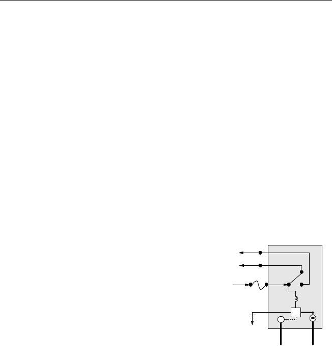
At start-up, the power switch is placed in the ON position, supplying approximately 12-volts DC to the heat-control circuitry
in the controller and to one side of the heat relay coils on the
interface board. If resistance in the temperature probe indicates the temperature in the frypot is below 180ºF (82ºC), the current flows
through a melt cycle circuit where a timer switch alternately closes for six seconds and opens for 24 seconds. If the temperature is 180ºF (82ºC) or above, the current flows through a heat circuit, bypassing the timer switch. In either case, ground is supplied to
the other leg of the heat relay coils, which closes electronic switches in the 24 VAC circuit to provide current to the ignition module. Circuitry in the ignition module sends 24 VAC to the gas valve via a normally closed high-limit switch. Simultaneously,
the module causes the ignitor to spark for four seconds to light the burner. A flame sensor verifies the burner ignition by measuring the flow of microamps through the flame. If the burner does not
light (or is extinguished), current to the ignition module is cut, the gas valve closes, and the ignition module “locks out” until the power switch is turned off and then back on. A normally closed drain switch is attached to the rear of the controller. If the drain is opened, the heat circuit is opened and all heating is discontinued. A probe monitors the temperature in the frypot. When the programmed setpoint temperature is reached, resistance in the probe causes the heat cycle circuitry in the controller to cut off current flow through the heat relay. This in turn cuts off the 24 VAC to the ignition module, causing the gas valve to close.
1-1
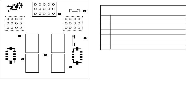
1.3Interface Board
All fryers in this series have an interface board located in the component box behind the control panel. The interface board provides a link between the controller and the fryer’s individual components without requiring excessive wiring, and allows the controller to execute commands from one central point.
K2 and K3 are double-pole-double throw (DPDT) relays that supply 24VAC to the ignition and gas valve circuits, as well as 120VAC to the blower motor. The relays on this board plug into sockets. If a relay fails, that relay can be replaced.
LEDs (labeled D1 through D7) are arrayed around the board to assist in troubleshooting.
INTERFACE BOARD
LED DIAGNOSTIC LIGHTS
D1 24 VAC to left gas valve (dual vat only)
D2 24 VAC to left ignition module (dual vat only)
D3 24 VAC from transformer
D4 24 VAC to right ignition module
D5 24 VAC to gas valve (right valve if dual vat)
D6 12 VAC from transformer
D7 CE and Japanese units only: air switch closed
NOTE: In full-vat fryers, the relay for the left side (K2) may not be present.
The chart on the following page illustrates current flow through the board, and the table at the top of page 1-4 identifies frequently used test points.
1-2

1-3 |
FREQUENTLY USED TEST POINTS FOR INTERFACE BOARD
TEST |
METER |
PINS |
RESULTS |
|
SETTING |
||||
|
|
|
||
12VAC Power to Controller |
50VAC Scale |
1 and 3 on J3 or J2 |
12-18 |
|
24VAC Power to Right Module |
50VAC Scale |
8 on J3 and GROUND |
22-28 |
|
|
|
|
|
|
120 VAC Power |
250VAC Scale |
11 on J3 and GROUND |
110-125 |
|
|
|
|
|
|
120 VAC Power to Blowers |
250VAC Scale |
12 on J3 and GROUND |
110-125 |
|
|
|
|
|
|
24VAC Power to Full or Right vat High-Limit |
50VAC Scale |
9 on J3 and GROUND |
22-28 |
|
24VAC Power to Left High-Limit (if present) |
50VAC Scale |
9 on J1 and GROUND |
22-28 |
|
Probe Resistance (Full or Right Vat) * |
R x 1000 OHMS |
2 and 6 on J3 or 13 and 14 on J2 |
** |
|
Probe Resistance (Left - if present) * |
R x 1000 OHMS |
2 and 6 on J1 or 14 and 15 on J2 |
** |
|
|
|
|
|
|
Probe Isolation |
R x 1000 OHMS |
6 on J1 or J3 and GROUND |
*** |
|
|
|
|
|
|
High-Limit Continuity (Full or Right Vat) |
R x 1 OHM |
9 on J3 and Wire 13C on Gas Valve |
0 |
|
|
|
|
|
|
High-Limit Continuity (Left - if present) |
R x 1 OHM |
9 on J1 and Wire 12C on Gas Valve |
0 |
|
|
|
|
|
*Disconnect 15-pin harness from controller before testing probe circuit.
**See Probe Resistance Chart on page 1-28.
***5 mega-Ohms or greater.
1.4Thermostats
BIGL30 series gas fryers have temperature probes located on the front centerline of each frypot. In this type of thermostat, the probe resistance varies directly with the temperature. That is, as the temperature rises, so does resistance, at a rate of approximately 2 ohms for every 1º F. Circuitry in the controller monitors the probe resistance and controls burner firing when the resistance exceeds or falls below programmed temperatures (setpoints).
BIGL30 series gas fryers are also equipped with a high-limit thermostat. In the event that the fryer fails to properly control the oil temperature, the high-limit thermostat prevents the fryer from overheating to the flash point. The highlimit thermostat acts as a normally closed power switch that opens when exposed to temperatures above 425ºF to 450ºF (218ºC to 232ºC). The different types of thermostats have different part numbers for CE and Non-CE models, and are not interchangeable.
1.5Accessing Fryers for Servicing
 DANGER
Moving a fryer filled with oil may cause spilling or splattering of the hot liquid. Follow the draining instructions in Chapter 5 of the BIGL30 Series Gas Fryer Installation and Operation Manual before attempting to relocate a fryer for servicing.
1.Shut off the gas supply to the unit. Unplug the power cords. Disconnect the unit from the gas supply.
2.Remove any attached restraining devices and relocate the fryer for service accessibility.
3.After servicing is complete, reconnect the unit to the gas supply, reattach restraining devices, and plug in the electrical cords.
1-4
1.6 |
Cleaning the Gas Valve Vent Tube |
1. |
Set the fryer power switch and the gas valve to the OFF position. |
2. |
Carefully unscrew the vent tube from the gas valve. NOTE: The vent tube may be straightened for ease of |
|
removal. |
3. |
Pass a piece of ordinary binding wire (.052 inch diameter) through the tube to remove any obstruction. |
4. |
Remove the wire and blow through the tube to ensure it is clear. |
5. |
Reinstall the tube and bend it so that the opening is pointing downward. |
1.7 |
Checking the Burner Manifold Gas Pressure |
1. On non-CE fryers only ensure that the gas valve knob is in the OFF position.
Honeywell |
ON |
OFF |
2. Remove the pressure tap plug from the gas valve assembly.
Pressure Tap Plug
Typical Non-CE |
Typical CE Valve |
Valve Assembly |
Assembly |
3.Insert the fitting for a gas pressure-measuring device into the pressure tap hole.
4.On non-CE fryers only, place the gas valve in the ON position.
5.Place the fryer power switch in the ON position. When the burner has lit and burned steadily for at least one minute, compare the gas pressure reading to the pressure for the corresponding gas in the appropriate table on the following page. The tables list the burner manifold gas pressures for each of the gas types that can be used with this equipment.
1-5

CE Standard
Burner Manifold Gas Pressures
|
|
|
Pressure |
|
|
|
|
|
|
|
(mbar) |
|
|
|
|
|
|
|
Single |
|
|
|
|
|
Gas |
|
Vat |
|
|
|
|
|
Natural Gas Lacq |
|
7 |
|
|
|
|
|
(G20) under 20 mbar |
|
|
|
|
|
|
|
|
|
|
|
|
|
|
|
Natural Gas Gronique |
* |
10 |
|
|
|
|
|
(G25) under 25 mbar |
|
|
|
|
|
|
|
|
|
|
|
|
|
|
|
Natural Gas Gronique |
|
10 |
|
|
|
|
|
(G25) under 20 mbar |
|
|
|
|
|
|
|
|
|
|
|
|
|
|
|
Butane/Propane |
|
17 |
|
|
|
|
|
(G30) at 28/30 or 50 mbar |
|
|
|
|
||
|
|
|
|
|
|
||
|
Propane |
|
20 |
|
|
|
|
|
(G31) under 37 or 50 mbar |
|
|
|
|
||
|
|
|
|
|
|
||
|
* Belgian G25 = 7,0 mbar |
|
|
|
|
|
|
|
|
|
|
|
|
|
|
|
|
|
|
|
|
|
|
|
|
|
|
|
|
|
|
|
|
|
|
|
|
|
|
Non-CE Standard
Burner Manifold Gas Pressures
|
|
Gas |
Pressure |
|
|
|
|
|
Natural |
3" W.C. |
|
|
|
|
|
0.73 kPa |
|
|
|
|
|
|
|
|
|
|
|
|
|
Propane |
8.25" W.C. |
|
|
|
|
|
2.5 kPa |
|
|
|
|
|
|
|
|
|
|
|
|
|
|
|
|
|
|
6. To adjust the burner gas pressure, remove the cap from the gas valve regulator and adjust to the correct pressure.
Non-CE |
CE |
Valve |
Valve |
GAS VALVE REGULATOR CAP
7.Place the fryer power switch (and the gas valve in non-CE fryers) in the OFF position. Remove the fitting from the pressure tap hole and reinstall the pressure tap plug.
1.8Measuring Flame Current
When the burner flame is properly adjusted, it will produce a current between 2.5 A and 3.5 A. Flame current is measured by placing a microamp (not milliamp) meter in series with the sensing wire on the ignitor. This is accomplished as follows:
1. Place the fryer power switch in the OFF position.
1-6
2.Disconnect the sensing wire from one of the burner ignitors and connect it to the positive lead of the meter. Connect the negative lead of the meter to the terminal from which the sensing wire was removed.
Flame Sensor Wire 
3.Place the fryer power switch in the ON position to light the burners. After the frypot temperature reaches 200 F (93 C), wait at least one minute before checking the reading. NOTE: The closer the unit is to normal operating temperature, the more accurate the reading will be.
1.9Replacing Fryer Components
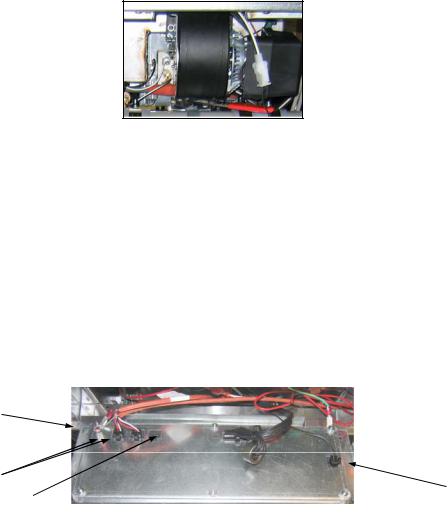
1.9.1 Replacing the Controller or the Controller Wiring Harnesses
1.Disconnect the fryer from the electrical power supply.
2.Open the control panel by removing the screws on the bottom of the bezel. Carefully lower the bezel.
3.Remove the two screws from the upper corners of the controller. The controller is hinged at the bottom and will swing open from the top.
4.Unplug the wiring harnesses from the connectors on the back of the controller marking their position for reassembly and disconnect the grounding wires from the terminals. Remove the controller by lifting it from the hinged slots in the control panel frame.
Ground Wire Terminal
 Ground Wire Terminal
 20-Pin Connector
Communication Wires
Locator Wire
Drain Switch
Manual M3000 controller.
5.Install the replacement controller. Reverse steps 1 thru 4.
6.Setup the manual M3000 controller following the instructions in the Installation and Operation manual. Setup MUST be performed after replacement.
7.Once setup is complete on all replaced controllers, reset all control power following the instructions in section 1.13.6 to readdress the new controller. Check software version and if necessary update the software. If a software update was necessary, follow the instructions to update the software in section 1.15 on page 1-34.
1.9.2Replacing the Temperature Probe, High-Limit Thermostat
1.Disconnect the fryer from the electrical supply.
2.Drain cooking oil below the level of the probe or thermostat.
3.Remove the screws on the bottom of the bezel. Carefully lower the bezel.
4.Remove the top two screws in the upper corners of the controller.
5.Swing the controller out from the top and allow it to rest on its hinge tabs.
6.Disconnect the controller wiring harness(es) and ground wire from the back of the controller and remove the controller by lifting it from the hinge slots in the control panel frame.
7.Disconnect the ignition cables from the ignitors by grasping the boots and gently pulling toward you.
8.Disconnect the flame sensor wires from the flame sensors.
9.Disconnect the sound device lead from the interface board.
1-7

10.If working on the left frypot, cut the wire tie on the wiring bundle and disconnect the main wiring harness 15-pin connector.
11.Remove the spark module boxes.
12.Remove the component box mounting screws.
13.Lower the component box far enough to expose the probes and carefully disconnect the wiring harness plug from the back of the box. This will leave one set of wires, enclosed in spiral wrap, connected to the component box.
14.Unscrew the probe or thermostat from the frypot.
15.Apply Loctite® PST56765 pipe thread sealant or equivalent to the replacement part threads and screw the replacement part into the frypot, torquing to 180 inch-pounds.
16.Connect the wires from the new component as follows:
a.If replacing the temperature probe, use a pin pusher to disconnect (one at a time) the red and white leads from the connector and insert the corresponding leads from the new probe into the plug..
b.If replacing the high-limit thermostat, use a pin pusher to disconnect the lead running to the connector and insert the corresponding lead from the new thermostat.
c.Disconnect the other lead from the drain safety switch and connect the remaining lead from the new thermostat.
17.Reverse steps 1 through 13 to complete the procedure.
1.9.3 Replacing the Interface Board
1.Perform steps 1 through 4 from section 1.9.1.
2.Disconnect the wires attached to the interface board, marking or making a note of the wires and terminals to facilitate reconnection.
3.Remove the nuts at each corner of the interface board and carefully pull it from the studs far enough to allow the connector on the back of the board to be disconnected, then remove the board from the box. When removing the board, be careful not to lose the spacers that fit over the studs behind the board.
4.Recover the relay(s) from the failed interface board and install on the replacement board.
5.Reverse the procedure to install the replacement board, being sure that the spacers behind the board are in place and the computer locator ground wire is attached to a stud.
1.9.4 Replacing an Ignition Module
1.Disconnect the fryer from the electrical supply.
2.Remove the screws on the bottom of the bezel. Carefully lower the bezel.
3.Remove the top two screws in the upper corners of the controller.
4.Swing the controller out from the top and allow it to rest on its hinge tabs.
5.Loosen the nuts attached to the screws of the module. Slide the module towards the rear of the component box until the nuts drop through the keyholes.
6.Carefully rotate the module and pull forward. On some units it may be necessary to remove the blower.
7.Disconnect the wires from the ignition module, marking or making a note of the wires and terminals to facilitate reconnection.
8.Remove the screws from the module.
9.Move the screws and spacers to the new module.
10.Reverse the procedure to install the replacement module.
1.9.5 Replacing an Ignitor Assembly
 DANGER
Drain the frypot or remove the handle from the drain valve before proceeding further.
1.Disconnect the fryer from the electrical supply.
2.Disconnect the flame sensor wire by carefully pulling its push-on terminal from the terminal strip on the ignitor. Disconnect the gas enrichment tube at the ignitor-end compression fitting. Disconnect the ignition cable from the ignitor by grasping its boot and gently pulling toward you. (See photo below)
1-8
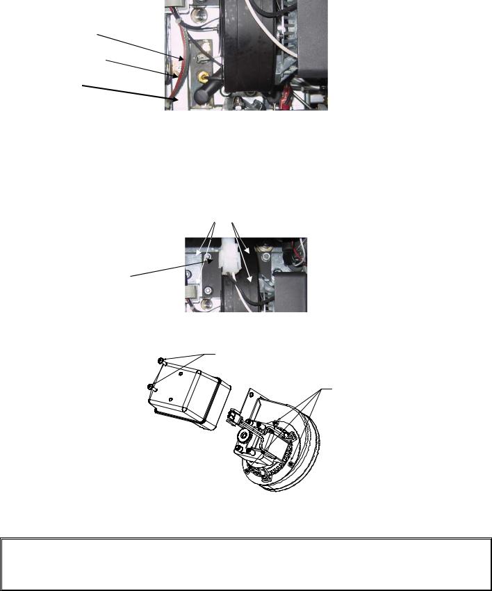
Flame Sensor Wire
Gas Enrichment Tube
Ignition Cable
3.Remove the sheet metal screws securing the ignitor to the mounting plate and pull the ignitor from the fryer.
4.Reverse the procedure to install the replacement ignitor.
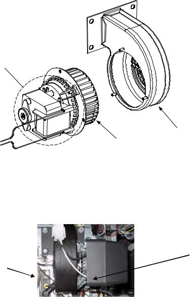
1.9.6 Replacing or Cleaning a Combustion Air Blower
1.Disconnect the blower wiring harness, remove the blower assembly mounting nuts, and remove the blower assembly from the fryer. If cleaning the motor, continue with Step 2; otherwise, install the replacement blower,
reconnect the wiring harness, and then go to Step 6.
Blower assembly mounting nuts
Wiring connection
2. Remove the blower motor shield and separate the blower motor from the housing as shown in the illustration below.
Remove these screws to remove the shield from the blower assembly.
Remove these nuts to separate the blower motor from the housing.
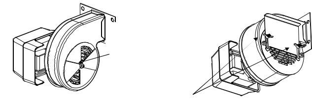
3.Wrap the motor with plastic wrap to prevent water from entering it. Spray degreaser or detergent on the blower wheel and the blower housing. Allow it to soak for five minutes. Rinse the wheel and housing with hot tap water, then dry with a clean cloth.
NOTICEAustralia Only
The air pressure switch on the combustion blower should read: Full Vat units-122pa (0.5 inches W.C.) and for Split Vat units-180pa (0.72 inches W.C.).
1-9
Wrap the motor and wires with plastic wrap or a plastic bag.
Blower Housing
Blower Wheel
4.Remove the plastic wrap from the blower motor assembly. Reassemble the blower motor assembly and blower housing. Reinstall the blower shield.
5.Reinstall the blower assembly in the fryer and reconnect the wiring disconnected in Step 1.
6.Light the fryer in accordance with the procedure described in Chapter 3, Section 3.2.2 of the BIGL30 Series Gas Fryer Installation and Operation Manual.
7.After the burners have been lit for at least 90 seconds, observe the flames through the burner viewing ports located on each side of the combustion air blower.
Right Viewing Port is behind motor.
Left Viewing
Port.
The air/gas mixture is properly adjusted when the burner manifold pressure is in accordance with the applicable table on page 1-6 and the burners display a bright orange-red glow. If a blue flame is observed or if there are dark spots on a burner face, the air/gas mixture requires adjustment. NOTE: Opening the air shutter too much may result in whistling. It should not be more than 1/3 open.
1.9.7 Adjusting the Air/Gas Mixture
On the side of the blower housing opposite the motor is a shutter plate with a locking nut. Loosen the nut enough to allow the shutter to be moved, then adjust the position of the shutter to open or close the air intake opening until a bright orange-red glow is obtained. Carefully hold the shutter in position and tighten the locking nut (see illustration on the following page).
1-10
On non-CE blowers, loosen this nut and rotate shutter to open or close air intake.
On CE blowers, loosen
both wing nuts and slide
the shutter to adjust the
air intake.
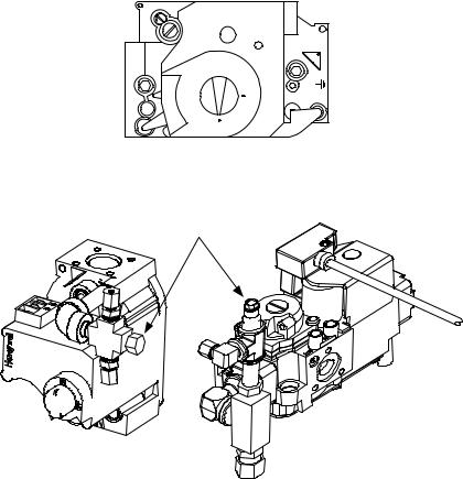
1.9.8 Replacing a Gas Valve
1.Disconnect fryer from electrical and gas supplies.
2.Disconnect the drain safety and high-limit thermostat wires from the gas valve. Mark each wire to facilitate reconnection.
3.Remove the vent tube (on non-CE fryers) and the enrichment tube fitting from the valve. Disconnect the flexible gas line(s).
If replacing the left-most valve on any configuration, or the right valve on a two-fryer battery, follow the instructions below. If replacing valves in other positions, skip to “ALL OTHER VALVES.”
A.Remove the filter pan from the unit. Remove the door adjacent to the valve being replaced.
B.Remove the screws that attach the pan rails adjacent to the valve being replaced.
C.Uncouple the pipe union and remove the gas valve and associated piping from the unit.
D.Remove the fittings and associated piping from the failed valve and install them on the replacement valve using Loctite® PST56765 or equivalent pipe thread sealant.
E.Reconnect the gas valve assembly to the fryer using Loctite® PST56765 or equivalent pipe thread sealant, and reattach the flexible gas line(s), enrichment tube(s), and the vent tube (on non-CE units). Reconnect the highlimit thermostat wires and drain safety wires to the valve.
F.Reconnect the fryer to the gas supply and open the cut off valve. Apply a thick soapy solution of water around each connection to check for gas leaks and ensure there are no bubbles. Eliminate any that are found. There should be no smell of gas.
G.Position the pan rail assembly beneath the fryer and rest the rear end of the rail on the cabinet frame. Install the two nuts and bolts behind the front face of the rail, but do not tighten them. Install the nut and bolt at the rear end of the filter rail and tighten securely.
H.Reattach the screws for the pan rails. Install the filter pan in the unit to make sure that all components are properly aligned.
I.Reconnect the fryer to the electrical power supply and check for proper operation. When proper operation has been verified, reinstall the door removed in Step A.
ALL OTHER VALVES
4.Carefully unscrew the valve from the manifold. NOTE: Some models may have the valve attached to the manifold by means of a pipe union. In such cases, remove the valve by uncoupling the union.
5.Remove all fittings from the old gas valve and install them on the replacement valve, using Loctite® PST56765 or equivalent pipe thread sealant.
6.Reconnect the gas valve assembly to the fryer using Loctite® PST56765 or equivalent pipe thread sealant, and reattach the flexible gas line(s), enrichment tube(s), and the vent tube (on non-CE units). Reconnect the highlimit thermostat wires and drain safety wires to the valve.
7.Reconnect the fryer to the gas supply and open the cut off valve. Apply a thick soapy solution of water around each connection to check for gas leaks and ensure there are no bubbles. Eliminate any that are found. There should be no smell of gas.
8.Reconnect the fryer to the electrical power supply and check for proper operation.
1-11
1.9.9 Replacing a Burner Assembly
1.Disconnect the unit from the electrical and gas supplies.
2.Remove the gas line and enrichment tube using a 7/16” and 5/8” wrench from the front of the burner.
3.Remove the elbow and tee off the bottom of the burner to ensure easier removal of the burner.
4.Remove the fryer back.
5.Remove the screws attaching the flue cap to the brace.
6.Remove the top cross brace in the back.
7.Remove the flue by removing the two screws in the rear and one screw in
the front of the flue. |
Figure 1 |
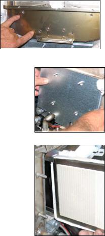
8.Remove all the screws on the flue collector and bend back the tabs and remove the collector.
9.Remove four screws on the collector insulation plate (see Figure 1).
10.Remove the four nuts and cover of the lower insulation retaining cover (see Figure 2).
11.Carefully remove the insulation.
12.Grasp the burner firmly and slide the burner out the rear of the fryer. Pull it toward you until it clears the burner channels, taking care not to damage the ceramic tiles in the process.
13.Slide the burner out the rear of the fryer.
14.Clean all debris from the burner channels and combustion area.
15.Inspect the upper and lower burner rails for cracked or burned out welds.
a.If the welds in the lower rail are cracked or burned out, the frypot must be replaced. Refer to Section 1.9.11 for procedure.
b.If the welds in the upper rail are cracked or burned out, the upper rail must be replaced. Refer to Section 1.9.12 for procedure.
16.Wrap a new insulating strip along the edges of the burner. NOTE: Use P/N 8260931 for full-vat frypots and P/N 826-0932 for dual-vat frypots.
17.Carefully slide the replacement burner into the rails starting at the top and lifting slightly up on the bottom (see Figure 3). Ensure that the insulation is not torn or damaged.
Figure 2
Figure 3
18.In reverse order, reassemble insulation and holding plates.
19.Install flue collector.
20.Install the flue.
21.Install the cross brace, ensuring the flue cap is secured to the brace.
22.Replace the fryer back.
23.Reattach the elbow, gas line and enrichment tubes to the front of the burner.
24.Fill the frypot with oil. Turn the fryer on; turn off or bypass the melt cycle and operate the unit for at least 10 minutes.
25.Examine the burner flame. The color and intensity on both sides should be the same.
26.Use an inspection mirror to check for leaks in areas that cannot be directly observed.
27.If a leak is detected, tighten all the lower insulation retainer nuts, allow the frypot to heat for five additional minutes, and repeat steps 25 and 26.
28.If a leak persists, use a rubber hammer and a small block of wood to tap the corners of the lower combustion chamber insulation retainers. Repeat steps 25 through 27. Repeat this step until no leakage is detected.
1-12

1.9.10 Replacing the Filter Motor, Filter Pump, or Filter Pump Solenoid Valve
1.Disconnect the unit from the electrical power supply.
2.Remove the filter pan from the unit.
3.Position a container beneath the oil return fitting at the front of the cabinet. Disconnect the flexible oil lines from the fittings, allowing any residual oil to drain into the container.
4.At the rear of the fryer, unplug the left connector (as viewed from the rear of the fryer) from the transformer box.
5.Remove the four nuts and bolts attaching the motor mount to the rear motor mount support.
6.At the front of the fryer, remove the cover plate from the front of the motor and disconnect the motor wires.
7.Place a 1-foot (30.5-cm) length of wood (or similar support) beneath the motor mount near the front of the unit and remove the two remaining nuts and bolts attaching the motor mount to the front cabinet cross-brace.
8.Carefully remove the support and lower the motor mount to the floor, allowing the rear of the mount to slide forward and off the rear motor mount support.
9.Disconnect the return flexline from the pump. The motor and pump assembly can now be pulled from beneath the fryer and the failed component can be removed and replaced.
10.Position the replacement motor and pump assembly beneath the fryer and reconnect the oil return flexline to the pump. Lift the rear of the motor mount up and onto the rear motor mount support.
11.Lift the front of the motor mount up and support it with a 1-foot (30.5-cm) piece of wood or a similar support. Install but do not tighten the two nuts and bolts that attach the motor mount to the front cabinet cross-brace.
12.Install and tighten the four nuts and bolts that secure the motor mount to the rear motor mount support.
13.At the front of the fryer, tighten the two nuts and bolts at the front of the motor mount. Reconnect the motor power wires and reinstall the wiring cover plate.
14.Reconnect the oil return flexline and reinstall the filter pan.
15.Reconnect the unit to the electrical power supply, fill the frypots with oil and check for proper operation.
1.9.11Replacing the Frypot
1.Disconnect the fryer from the electrical and gas supplies.
2.Remove the filter pan from the unit and drain one frypot at a time into a Shortening Disposal Unit (SDU) or other appropriate metal container.
 DANGER
DO NOT attempt to drain more than one full frypot into the SDU at one time.
3.Open the control panel by removing the two screws on the bottom of the bezel. Carefully lower the bezel.
4.Remove the top screws in the upper corners of the controller.
5.Grasp the upper edge of each controller and swing the controller downward. Unplug the controller wiring harness and grounding wire from the back of each controller.
6.Remove the controllers by lifting them from the hinge slots in the control panel frame.
7.Disconnect the sound device wire from the interface board.
8.Disconnect the flame sensor wires by carefully pulling the push-on terminals from the terminal strips on the ignitors. Disconnect the gas enrichment tube at the ignitor-end compression fitting. Disconnect the ignition cables from the ignitors by grasping the boots and gently pulling toward you.
9.Dismount the topcap by removing the screws on the bottom of each front corner and lifting the topcap straight up.
10.Remove the two mounting screws on each side of the component box and rotate the top of the box out of the frame. Carefully pull it out enough to disconnect the wiring harness connector from the back of the box. Cut any ties that prevent the box from being pulled out of the control panel frame.
11.Carefully pull the box clear of the frame and rest it on top of the fryer.
12.Using a pin pusher, remove the temperature probe, high-limit thermostat wires and RTD probe wires from the plugs or terminals, marking each wire to facilitate re-assembly.
13.Remove the cover from the safety drain switch. Disconnect the wires from the switch.
14.Disconnect any auto top-off sensors if equipped and wiring.
15.Remove the section(s) of drain from the drain valve(s) of the frypot to be removed.
1-13
16.Disconnect the gas lines from the burner orifices and ignitor assemblies.
17.Remove the frypot hold down bracket.
18.Remove the screws in the back panel and inside the flue cap at each end that secure the flue cap to the fryer and lift it clear of the fryer.
19.Disconnect the oil return line(s) from the frypot to be removed.
20.Carefully lift the frypot from the fryer cabinet.
21.Remove the drain valve(s), temperature probe(s), high-limit thermostat(s), RTD probes and igniter assemblies.
Inspect each of these components carefully and install them in the replacement frypot if they are in serviceable condition. Use Loctite® PST56765 sealant or equivalent on component threads.
NOTE: Some servicers, based upon their experience, recommend that probes and thermostats be replaced whenever a frypot is replaced; however, this remains the customer’s decision.
20.Reverse steps 1-19 to reassemble fryer.
NOTE: Care should be taken not to over-torque nuts on frypots made of 400-series stainless steel, as this could tear the material. One turn past hand-tight is sufficient torque.
21.Perform steps 14 through 18 of Section 1.9.9 to ensure that there are no leaks in the burner insulation.
 CAUTION
Before installing temperature probe, high-limit thermostat, RTD probe and drain valve on replacement frypot, clean the threads and apply Loctite® PST56765 thread sealant or equivalent.
1.9.12 Replacing Frypot Insulation and/or Upper Burner Rails
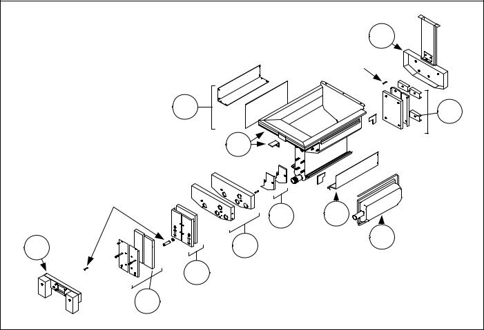
NOTE: Replacing the burner rails requires completely tearing down the frypot and installing new frypot insulation. Refer to the frypot exploded view (on next page) for component identification.
1.Remove the frypot per Section 1.9.11.
2.Remove the burner assemblies (1).
3.Remove insulation retainers and blanket insulation (2).
4.Remove the upper oil zone insulation bracket and upper oil zone insulation (3).
5.Remove the plenum (4).
6.Remove the front lower combustion chamber insulation retainer and insulation (5) and the front lower combustion chamber inner insulation retainer and insulation (6). NOTE: Full-vat units have two-piece insulation retainer and insulation components. Dual-vat units have one-piece components.
7.Remove the upper combustion chamber insulation retainer and insulation (7).
8.Remove the inner upper combustion chamber insulation retainer and insulation (8).
9.Remove the rear lower combustion chamber retainers, back, and insulation (9). NOTE: Full-vat units have twopiece backs and four retainers. Dual-vat units have one-piece backs and two retainers.
10.Remove the flue assembly (10).
1-14
|
|
10 |
|
|
Spacer |
|
2 |
9 |
|
|
|
|
3 |
|
Spacer |
|
|
s |
8 |
11 |
|
||
4 |
7 |
1 |
|
||
|
6 |
|
5 |
Disassembling A Frypot |
|
|
(Full Vat Illustrated) |
|
See page 1-17 for reassembly illustration.
11.Remove the upper burner rails (11). NOTE: For the following steps, refer to the frypot exploded view on page 1- 15 for component identification.
12.Remove any residual insulation, sealant, and/or oil from the exterior of the frypot.
13.Place the “L” shaped pieces of the combustion chamber insulation (1) in the front and rear corners of both upper rail-retaining slots. (See page 1-17).
14.Using a mallet and short piece of wood, tap the corner tabs of the combustion chamber over the insulation to ensure a solid seal of the burner.
15.Install the upper burner rails (2) with the heat deflectors slanting toward the rear of the frypot. The rails will cover the “L” shaped pieces of combustion chamber insulation previously installed.
16.Place the upper inner combustion chamber insulation and insulation retainers (3) on the top two studs on each side of the front of the frypot and secure with ¼”-20 washer-nuts. It is normal for the retainers to slice off the overhanging insulation.
17.Place the lower rear combustion chamber insulation (4) on the lower four studs at the rear of the frypot.
18.Place one 1.625-inch tubular spacer (5) on each of the flue assembly (upper) studs at the rear of the frypot. NOTE: There are three different sizes of spacers. Verify the size to ensure the correct spacers are installed.
19.Press the flue assembly (6) over the burner rails. It may be necessary to use a rubber mallet or screwdriver to align the components. Use four ¼”-20 washer nuts to secure the flue assembly. Do not tighten the retainer nuts at this point. They should be finger-tight only. NOTE: The flue edge will cover one to two inches of the lower insulation.
20.Install the lower rear combustion chamber back(s) and retainer(s) (7) with the flanged edge(s) against the flue. Secure with ¼”-20 washer nuts. NOTE: Full-vat units have two-piece backs and four retainers. Dual-vat units come with one-piece backs and only two retainers.
1-15
21.Insert the burners (9) into the rails to ensure the rail spacing and alignments are correct. The burner should slide freely into and out of the rails. The upper rail can be bent slightly to increase or decrease tension on the burner and the edges of the slot can be closed or opened slightly to best fit the burner frame.
22.Carefully wrap a strip of burner insulation (8) tightly around the rear and sides of the burner frame (9), with the glass-tape side of the strip on the outside. Do not use duct tape or adhesive to secure the strip to the burner frame.
23.Align the burner to the burner rails while maintaining tension on the insulation strip. Insert the burner at a slight angle and begin pushing the burner slowly into the rails until it contacts the rear combustion chamber. The fit should be snug, but not excessively tight.
24. Verify that the burners are flush with the front edge of the burner rails. Remove the excess burner insulation by cutting with a knife or diagonal pliers. Do not try to tear the insulation!
25.Insert the upper front insulation (10) into its retainer (11), making sure that the holes in each piece are aligned with one another. Install the assembly with the insulation side toward the frypot and secure with ¼”-20 washernuts. Do not over tighten.
26.Place a washer on each of the four lower studs on the front of the frypot. Install the lower inner front insulation
(12)with the rectangular openings toward the drain valve nipple. Install the lower inner front insulation
retainer(s) (13). NOTE: Full-vat units have a two-piece insulation retainer. Dual-vat units have a one-piece retainer.
27.If necessary, replace the sight-glasses and insulation (14).
28.Place one washer and one 1.888-inch spacer (15) on each stud. NOTE: There are three different sizes of spacers. Verify the size to ensure the correct spacers are installed.
29.Insert the front lower insulation (16) into the front lower insulation retainer(s) (17) and install assembly on frypot. Secure with ¼”-20 washer-nuts. If frypot uses two retainers, connect them together with two ¼” selftapping screws. NOTE: Full-vat units have a two-piece insulation retainer and two pieces of insulation. Dual-vat units have one-piece components.
30.Return to the rear of the frypot and fully tighten all washer-nuts.
31.Remove and replace the plenum gaskets (18).
32.Place a 0.938-inch spacer (19) on the plenum-mounting studs, and mount the plenum (20). Ensure the gaskets are clear of the burner tubes by pulling the plenum back slightly. Place a washer on each stud and secure plenum with ¼”-20 lock-nuts.
33.Install the upper oil-zone insulation (21) by pressing it under the upper combustion chamber metalwork. Secure the insulation with the bracket (22) and ¼” self-tapping screws.
34.Install the upper burner rail blanket insulation (23). Position any excess insulation toward the top of the frypot. Avoid overhang past the bottom of the upper burner rail. Overhang in this area will make future burner replacement more difficult.
35.Cover the insulation with the insulation retainer (24), and secure with ¼” self-tapping screws.
36.Reinstall probes, drain valves, high-limit thermostats, and other pipe fittings using Loctite® PST56765 sealant or equivalent on the threads.
1-16
 Loading...