

Page 1
Part Number 508033 Rev . M
2008T
HEMODIALYSIS
SYSTEM
PREVENTIVE
MAINTENANCE
PROCEDURES
Page 2

FRESENIUS MEDICAL CA RE
NORTH AMERICA
800-227-2572
Fresenius Medical Care North America
920 Winter St.
Waltham, MA 02451
Manufactured by:
Fresenius USA, Inc.
4040 Nelson Avenue
Concord, CA 94520
2008T Preventive Maintenance Procedures
P/N 508033 Rev. M
Page ii
Page 3

2008T
HEMODIALYSIS SYSTEM
PREVENTIVE MAINT ENANCE
PROCEDURES
Part Number 508033 Rev. M
INCLUDING
PREVENTIVE MAINTENANCE CHECKLISTS
SIX (6) MONTH AND ANNUAL/4000 HOUR
http://www.fmcna.com
Copyright 2008 – 2019 F res e ni us Me di c al C ar e, All Rights Reserved.
2008T Preventive Maintenance Procedures
P/N 508033 Rev. M
Page iii
Page 4
2008T Preventive Maintenance Procedures
This document contains proprietary information of Fresenius USA, Inc. d/b/a Fresenius Medical
Care North America and its affiliates (“Fresenius Medical Care”). The contents of this document
may not be disclosed to third parties, copied, or duplicated in any form, in whole or in part,
without the prior written permission of Fresenius Medical Care.
Fresenius Medical Care, the triangle logo, 2008, BlueStar, bibag and DIASAFE are trademarks
of Fresenius Medical Care Holdings, Inc., or its affiliated companies. All other trademarks are
the property of their respective owners.
Caution: US Federal law restricts this device to sale only by or on the order of a physician.
Frequency, duration, and parameters of treatment are to be determined by the prescribing
physician.
Installation, maintenance, calibration and other technical information may be found in the
2008T Technician’s Manual, P/N 490130.
Contact Fresenius Medical Care Technical Support for applicable Field Service Bulletins. The
spare parts manual for the model 2008T and other information may be found on our web site at
www.fmcna.com
Indications for Use: The 2008T hemodialysis machine is indicated for acute and chronic dialysis
therapy in a healthcare facility.
Additional therapy options for patients receiving hemodialysis include: Isolated Ultrafiltration,
Sustained Low Efficiency Dialysis (SLED), and low volume hemodialysis (patients weighing ≥
20kg and ≤ 40 kg). This machine accommodates the use of both low flux and high flux dialyzers.
The SLED therapy option is not to be used for patients weighing ≤ 40 kg. The 2008T
Hemodialysis Machine is not to be used for plasma replacement therapies, for patients weighing
less than 20 kg, or for renal therapies using substitution fluid.
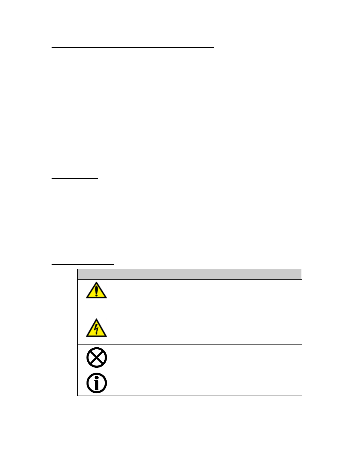
Conventions
Symbol Description
Warning! A warning is a statement that identifies conditions or
actions that could result in personal injury or loss of life.
Warnings found in this manual outside of this section are
designated with the warning symbol.
Shock Hazard: A shock hazard warning refers to a risk of a
possibly severe electrical shock due to improper use or handling
of the equipment.
Caution: A caution is a statement that identifies conditions or
actions that could result in damage to the machine.
Note: Notes are advisory comments or recommendations
regarding practices or procedures.
Page iv
2008T Preventive Maintenance Procedures
P/N 508033 Rev. M
Page 5

PREVENTIVE MAINTENANCE PROCEDURES
TABLE OF CONTENTS
1.0 INTRODUCTION ............................................................................................................................................ 1
1.1 SUPPLIES NEEDED .................................................................................................................... 2
1.2 TEST EQUIPMENT NEEDED ...................................................................................................... 3
1.3 OPERATING MODES .................................................................................................................. 4
1.4 FRONT PANEL CONTROLS ....................................................................................................... 5
1.5 MEASURING FLUID VOLUMES .................................................................................................. 7
2.0 SIX (6) MONTH PREVENTIVE MAINTENANCE ........................................................................................... 8
2.1 FILTERS .................................................................................................................................... 10
2.2 PRE-UF PUMP FILTER ............................................................................................................. 10
2.3 UF PUMP CHECK VALVES....................................................................................................... 11
2.4 HIGH VOLTAGE AC CONNECTIONS ....................................................................................... 11
2.5 UF PUMP ................................................................................................................................... 12
2.6 CONDUCTIVITY ........................................................................................................................ 12
2.7 TEMPERATURE ........................................................................................................................ 13
2.8 ALARM OPERATION AND PRESSURE HOLDING TESTS ...................................................... 14
2.9 VERIFY PH ................................................................................................................................ 16
2.10 POWER FAILURE ALARM ........................................................................................................ 16
2.11 FINAL CHECKS ......................................................................................................................... 17
ANNUAL (4000 HOUR) PREVENTIVE MAINTENANCE ............................................................................ 18
3.0
3.1 FILTERS AND O-RINGS............................................................................................................ 18
3.2 PRE-UF PUMP FILTER ............................................................................................................. 19
3.3 UF PUMP CHECK VALVES....................................................................................................... 19
3.4 DIAPHRAGM PUMPS ................................................................................................................ 19
3.5 HEATER ELEMENT ................................................................................................................... 20
3.6 HIGH VOLTAGE AC CONNECTIONS ....................................................................................... 20
3.7 DEAERATION MOTOR BRUSHES ........................................................................................... 21
3.8 INLET WATER PRESSURE REGULATOR ............................................................................... 22
3.9 ONLINE CLEARANCE TEST (IF APPLICABLE) ....................................................................... 23
3.10 DEAERATION AND LOADING PRESSURE.............................................................................. 26
3.11 FLOW RELIEF PRESSURE....................................................................................................... 27
3.12 CONCENTRATE (ACID) AND BICARBONATE PUMPS ........................................................... 28
3.13 UF PUMP ................................................................................................................................... 28
3.14 CONDUCTIVITY ........................................................................................................................ 28
3.15 TEMPERATURE ........................................................................................................................ 28
3.16 VOLT HI LO DETECT ................................................................................................................ 28
3.17 BLOOD LEAK AND DIMNESS ................................................................................................... 29
3.18 ARTERIAL, VENOUS AND TRANSMEMBRANE PRESSURE .................................................. 30
3.19 DIALYSATE FLOW .................................................................................................................... 33
3.20 HEPARIN PUMP ........................................................................................................................ 33
3.21 BLOOD PUMP ........................................................................................................................... 36
3.22 LEVEL DETECTOR ................................................................................................................... 38
3.23 ALARM OPERATION AND PRESSURE HOLDING TESTS ...................................................... 40
3.24 VERIFY PH ................................................................................................................................ 40
3.25 RINSE CHECKS ........................................................................................................................ 41
3.26 POWER FAILURE ALARM AND BATTERY REPLACEMENT ..................................................
3.27 BLOOD PRESSURE MODULE .................................................................................................. 43
3.28 INSPECT DIALYSATE LINES .................................................................................................... 47
3.29 FINAL CHECKS ......................................................................................................................... 47
REBUILDING THE DIAPHRAGM PUMPS .................................................................................................. 48
4.0
4.1 REBUILDING THE ULTRAFILTR ATION PUMP ........................................................................ 48
4.2 REBUILDING THE CONCENTRATE (ACID) AND BICARBONATE PUMPS ............................ 51
4.3 TESTING CONCENTRATE (ACID) AND BICARBONATE PUMPS ........................................... 53
PREVENTIVE MAINTENANCE CHECKLIST SIX (6) MONTH ............................................................................ 56
PREVENTIVE MAINTENANCE CHECKLIST ANNUAL/4000 HOUR .................................................................. 58
42
2008T Preventive Maintenance Procedures
P/N 508033 Rev. M
Page v
Page 6
General Warnings
may result in electrical shock to the operator or patient
Institute of Standards and Technology (National Bureau of Standards)
Improper functioning of the level detector may be caused by a clot of blood.
from that supplied may result in measurement errors.
operating normally.
Refer to the “General Warning” section in the 2008T Hemodialysis Machine Operator’s
Manual (P/N 490122) for a complete listing of general warnings.
Warning! Never perform maintenance when a patient is connected to the machine.
If possible, remove the machine from the treatment area when it is being serviced.
Label the machine to ensure it is not accidentally returned to clinical use before the
service work is completed. Always fully test the machine when maintenance is
completed. Confirm dialysate conductivity and pH level before returning the machine
to clinical use.
Shock Hazard: Refer servicing to qualified personnel. The electrical source must
be 120 volts, 60 Hz, single phase. The outlet must be a three-conductor type with a
hospital-grade receptacle and a ground fault interrupter. Test the polarity and ground
integrity before installation and ensure it is maintained thereafter. Failure to do so
Warning! Calibration procedures must be performed using primary standards or by
using standards that are regularly calibrated in a program traceable to the National
Warning! Calibrate the Level Detector module for the model of venous line being
used. During calibration ensure the filter inside the drip chamber is below the sensor
heads. Also verify that the venous clamp fully occludes the line when closed.
Warning! Failure to install, operate and maintain this equipment according to the
manufacturer’s instructions may cause injury or death to the patient or the operator. If
this equipment is modified, appropriate inspection and testing must be conducted to
ensure continued safe use of the equipment. Substitution of a component different
Warning! Use of this equipment adjacent to or stacked with other equipment should
be avoided because it could result in improper operation. If such use is necessary, this
equipment and the other equipment should be observed to verify that they are
Warning! Only Original Equipment Manufacturer (OEM) Fresenius Medical Care
parts should be used in the repair or upgrade of the Fresenius Medical Care 2008T
Hemodialysis System. Although, parts may look similar to parts in various vendor
catalogs or brick and mortar stores the 2008T Hemodialysis System uses parts that
have been specified and tested in accordance to ANSI/AAMI/ISO guidelines. The use
of non-OEM parts will void your warranty and may cause patient harm.
Note: This document is written for the 2008T Hemodialysis Systems using software
versions 1.04 or later.
2008T Preventive Maintenance Procedures
P/N 508033 Rev. M
Page vi
Page 7

1.0 INTRODUCTION
Preventive Maintenance for the 2008T Hemodialysis System is simple and straightforward.
Scheduled maintenance is performed based on timed intervals or number of hours a
machine is operated, whichever comes first. The time and hour intervals are as follows:
Machines without Extended Life Pump Components3
• Six (6) months
• Annually or after 4000 hours of operation
Machines with Extended Life Pump Components3
• Six (6) months
• Annually or after 4000 hours of operation
• Concentrate (acid), Bicarbonate & UF Pumps with extended life components3
are rebuilt every 2 years or after 8000 hours of operation.
2008T BlueStar™ Premium Ma chines
2008T BlueStar Premium machine are equipped with extended life components3 and can
be identified by the 2008T BlueStar logo (shown below) on the keyboard.
• Six (6) months
• Annually or after 4000 hours of operation
• Concentrate (acid), Bicarbonate & UF Pumps with extended life components3
are rebuilt every 2 years or after 8000 hours of operation.
The maintenance procedures have been devised to require a minimum of time while
ensuring that the machine is maintained in optimum operating condition.
Included in the Preventive Maintenance procedures are tests to verify normal machine
operation. Should the machine fail to pass any of these tests, repair or re-calibrate as
needed, then repeat the tests until the specifications are met before returning the
machine to service.
Checklists are provided in the back of this manual to record the work done. Make
copies of these checklists as needed. Your initials on the checklist certifies that each
procedure has been completed and that the machine is performing according to the
specifications given.
3
Refer to Sections 4.1 and 4.2 on how to recognize extended life pump components.
2008T Preventive Maintenance Procedures
P/N 508033 Rev. M
Page 1
Page 8

1.1 SUPPLIES NEEDED
A number of small parts must be available to perform the Preventive Maintenance (PM).
Kits are available that include the necessary parts needed, except for the 9-Volt battery
that must be replaced annually. An NEDA 1604AC heavy-duty (alkaline type) battery is
required.
Machines without Extended Life Pump Components3
o 2008T Annual PM Kit (part number 191108)
Machines with Extended Life Pump Components3
o 2008T BlueStar Premium One Year PM Kit (part number 191175)
o 2008T BlueStar Premium Two Year PM Kit (part number 191174)
2008T BlueStar Premium1 Machines
• 2008T BlueStar Premium One Year PM Kit (part number 191175)
• 2008T BlueStar Premium Two Year PM Kit (part number 191174)
Note: The 2008T BlueStar Premium Two Year PM Kit includes all of the
items in the 2008T BlueStar Premium One Year PM Kit along with the
necessary extended life components3 to rebuild the concentrate (acid),
bicarbonate and UF pumps every 2 years or 8000 hours.
1
Refer to Section 1.0 on how to recognize a 2008T BlueStar Pre mium ma chine .
3
Refer to Sections 4.1 and 4.2 on how to recognize extended life pump components.
2008T Preventive Maintenance Procedures
P/N 508033 Rev. M
Page 2
Page 9
1.2 TEST EQUIPMENT NEEDED
In addition, the following test equipment is needed:
Warning! Test equipment used must be maintained and/or calibrated per the
test equipment manufacturer’s requirements. In particular, the dialysate meter
must meet the specifications listed below. Refer to the test equipment's'
operator's manual, or contact the manufacturer for calibration and maintenance
requirements. Failure to properly maintain and calibrate test equipment could
lead to improper calibration and/or failure of the device to meet its
specifications.
Warning! Disinfect the machine internally and externally and check all
pressure transducer protectors for contamination before working on the
machine.
• 2008T Calibration Procedures (part number 508032).
• Test Kit (part number 150034), which contains two pressure gauges with fittings and
hoses for measuring loading pressure and deaeration pressure.
• Dialysate meter to measure dialysate pressure, temperature and conductivity at the ends
of the dialysate lines. The meter must be capable of making pressure measurements
from -250mmHg to +400mmHg with an accuracy of at least ±3mmHg. The
temperature function of this meter must be accurate within 0.2°C from 20°C to 45°C
and must be capable of measuring dialysate temperatures up to 85°C with an accuracy
of at least ±4.0°C. The conductivity function of this meter must be accurate to within
0.1mS over a range of 12mS to 17mS at a temperature of 25°C.
• Stopwatch with a resolution to 0.01 second and an accuracy of 0.01% or better.
• Buret, 25ml capacity with 0.1ml graduations (part number 290104).
• Graduated cylinder: 1000ml capacity with a tolerance of 5.0ml at 1000ml or better.
• Syringe, 60cc capacity. Tolerance is not important; the syringe is not used for volume
measurements.
• Tubing for Buret tip, 24” long (part number 545325-10). Use on the tip of the Buret.
• Resistor Plug Set for OLC Testing (part number 190168).
The following equipment is also required to test the blood pressure module:
• Dummy Cuff (part number 370090). The Dummy Cuff contains two air chambers with
calibrated volumes.
• Mercury manometer or equivalent pressure meter accurate to within 1mmHg at
pressures up to 330mmHg.
Page 3
2008T Preventive Maintenance Procedures
P/N 508033 Rev. M
Page 10

1.3 OPERATING MODES
The following preventive maintenance procedures contain instructions to place the
2008T into Dialysis Mode and Service Mode.
To place the machine in Service Mode, turn the machine power On and wait for the
message Press CONFIRM for Service Mode to appear. Once it appears, press the
[CONFIRM] key and the message will change to Machine in Service Mode. After
the System Initializing process is complete, the machine will be in Service Mode.
If the [CONFIRM] key is not pressed when the Press CONFIRM for Service Mode
message is on the screen, the screen will change and the message Machine in
Dialysis Mode will appear. After the System Initializing process is complete, the
machine will be in Dialysis Mode.
2008T Preventive Maintenance Procedures
P/N 508033 Rev. M
Page 4
Page 11

1.4 FRONT PANEL CONTROLS
Data Button
The front panel consists of four areas, the display screen, the key pad, a full keyboard
and a touch pad. The display screen is the area under the glass in the center of the
front panel. The key pad is to the right of the display screen and contains membrane
keys. Note the keyboard and touch pad fold down 90 degrees from under the display
screen and key pad.
Throughout the preventive maintenance procedures, whenever a key is to be pressed,
the appropriate key name is surrounded by square brackets as in the following
example:
Press the [CONFIRM] key and the screen will change.
In this example, the [CONFIRM] key on the touch pad should be pressed.
Touch Pad Operation
The touch pad is designed to allow the user to move an arrow around on the display
screen. To select a button during a procedure, use the touch pad to move the arrow
over the button on the screen. Tap the touch pad to select the on screen button.
Depending on the type of button, the screen will change. Data boxes are also
displayed on the display screen. The following describes the type of buttons and data
boxes that will be encountered during the preventive maintenance process.
A yellow data button is used to enter a measured volume or
value. When the yellow area of the data button is selected,
it will change to a darker yellow. The data can be changed
using the [▲] and [▼] keys or the value can be entered using
the number keys. Once the data is entered, press the
[CONFIRM] key and the data button changes back to light
yellow. The [Escape] key can be pressed when the data
button is dark yellow to abort the data entry and return it to
light yellow. The entered data does not get stored until the
[CONFIRM] key is pressed.
Some data buttons will change the screen and the data entry
will be performed on the new screen.
A gray data button means the button is not active and
selecting it will have no effect.
2008T Preventive Maintenance Procedures
P/N 508033 Rev. M
Page 5
Page 12
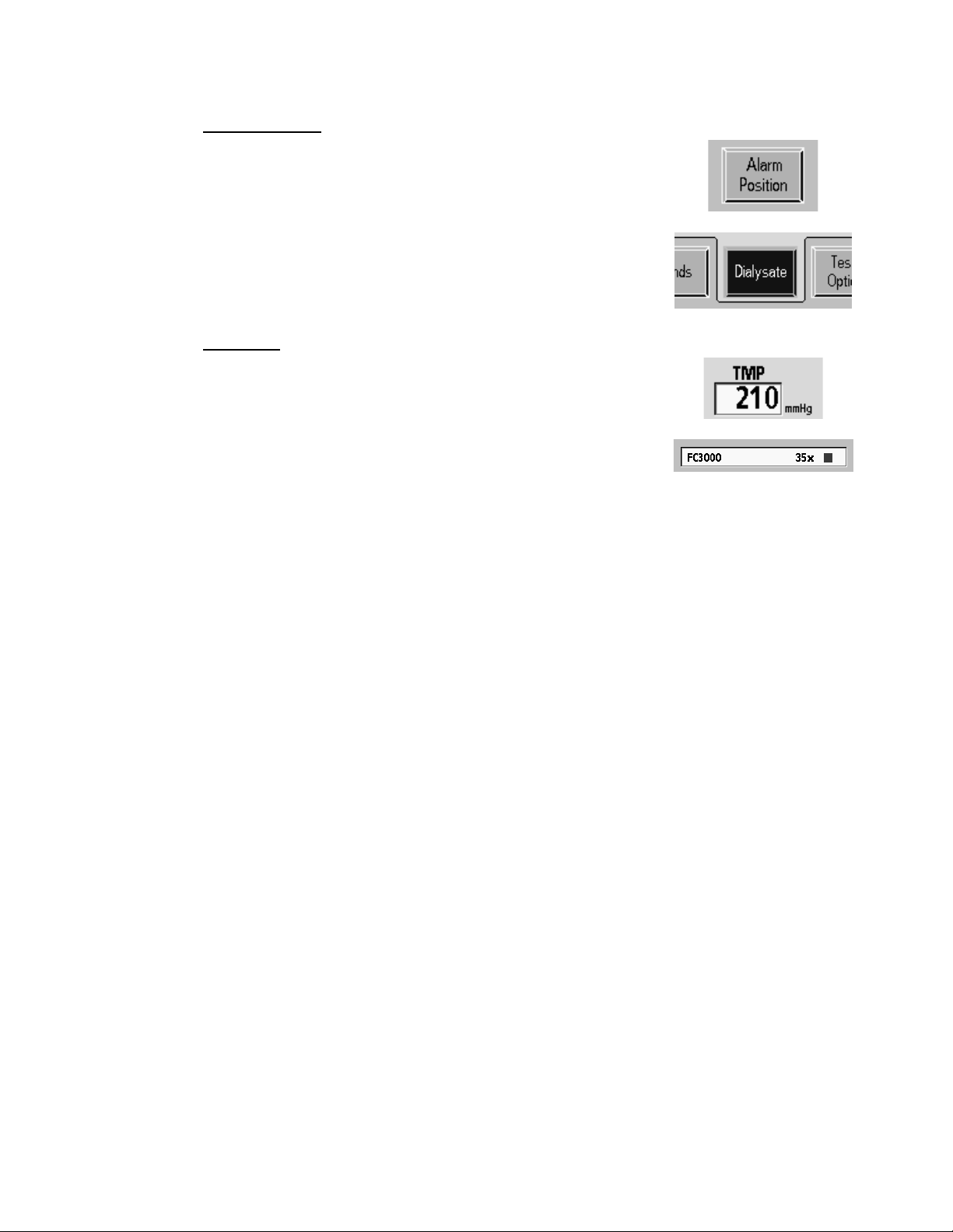
Screen Button
Blue rectangles on the display screen are screen buttons. By
Data Box
selecting the blue area of the screen button the display will
either change to another screen or the selection of an option
will change. A screen button is not active if it is gray.
This type of box shows selected data or data the machine is
measuring. During the preventive maintenance process this
type of box is used to verify a value or selection.
2008T Preventive Maintenance Procedures
P/N 508033 Rev. M
Page 6
Page 13
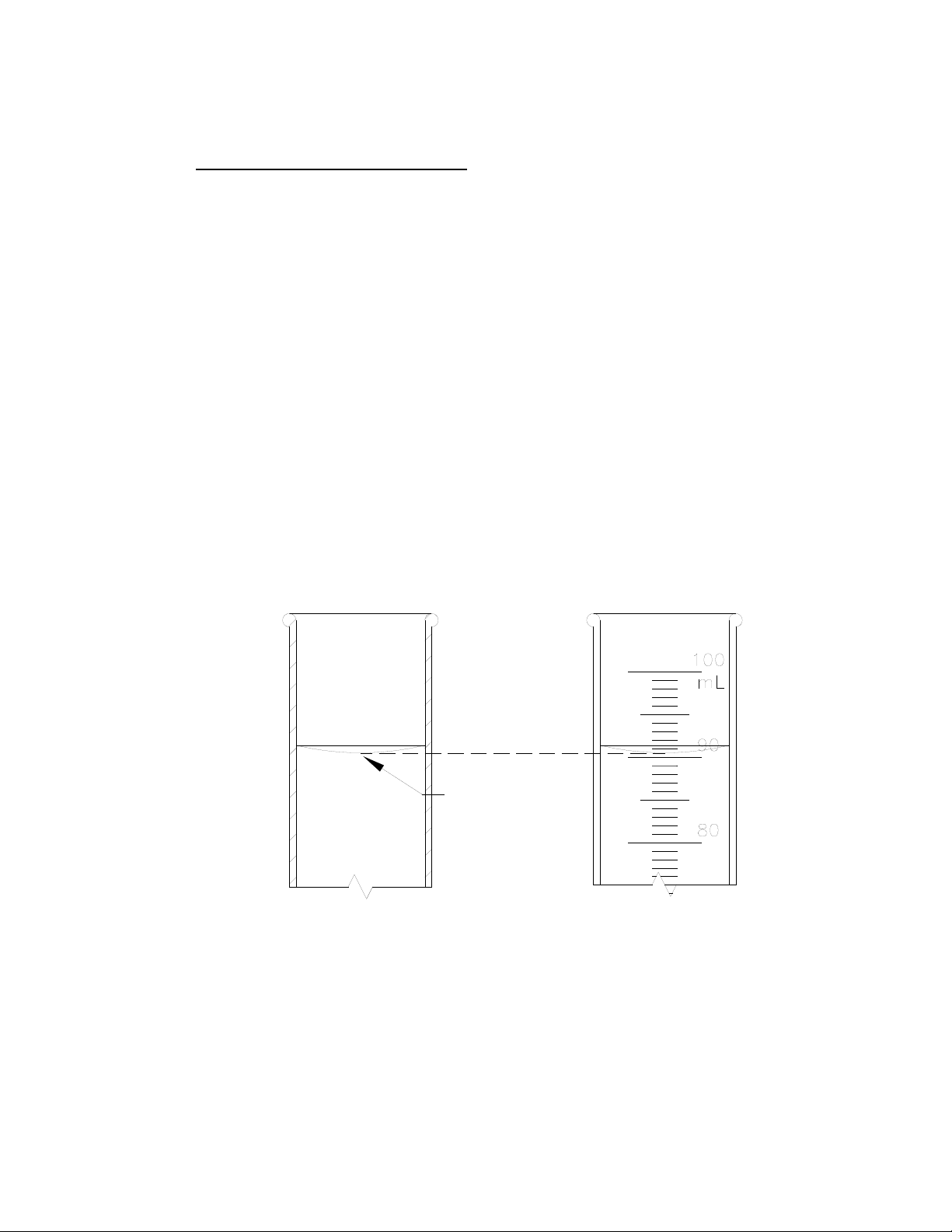
1.5 MEASURING FLUID VOLUMES
BOTTOM OF
MENISCUS
CURVE
Several of the following procedures require measuring fluid volumes using graduated
cylinders and laboratory burets. When making these measurements do the following:
• Make certain the container is clean and dry before collecting the fluid to be
measured. Two drops of fluid are approximately 0.1ml, which is enough to
affect the accuracy of critical measurements.
• Ensure that no items such as thermometers or tubing are allowed to come in
contact with the fluid in the graduate. Such items will change the calibration of
the graduate and affect the accuracy of measurements. Both the total volume
indicated and the amount of fluid indicated by each increment on the graduated
scale will be incorrect. For example, if a graduate is calibrated in 1ml
increments, a piece of tubing in contact with the fluid will cause each increment
to be less than 1ml, depending upon the total volume of the tubing that penetrates
into the fluid.
• Surface tension causes the fluid to curve into a meniscus (See Figure 1).
Measure the volume at the bottom of the meniscus curve as shown.
Figure 1. Meniscus Curve.
2008T Preventive Maintenance Procedures
P/N 508033 Rev. M
Page 7
Page 14

2.0 SIX (6) MONTH PREVENTIVE MAINTENANCE
Perform the following Preventive Maintenance procedures every six (6) months of
machine operation.
Make copies of the Six (6) Month Preventive Maintenance Checklist provided in
the back of this manual and use them to record the maintenance done.
Note: When performing an Annual Preventive Maintenance do not perform
the six (6) month procedures below first. Go directly to Section 3 and perform
the annual procedures described there.
While performing the following procedures, check the floor of the hydraulic unit and
all surfaces for moisture that might indicate a leak. Locate and correct any leaks
detected. Clean the floor of the hydraulic unit so that future leaks will be readily
apparent. Also, check all electrical connectors that can be reached to be sure they are
fully seated and there is no strain on the electrical cables.
2008T Preventive Maintenance Procedures
P/N 508033 Rev. M
Page 8
Page 15
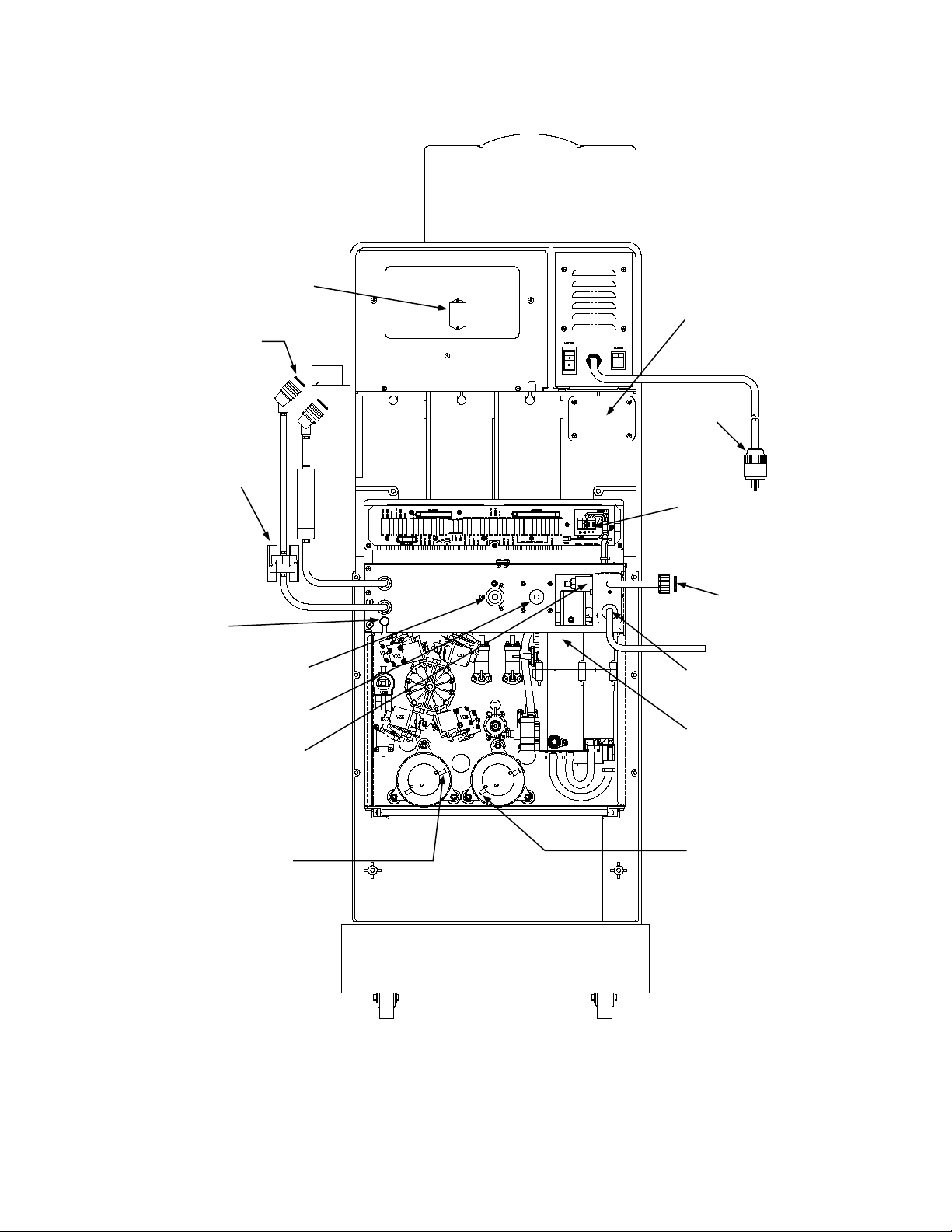
DIALYSATE LI N E
CONN. O-RINGS
P/N M42674
FLOW PUMP
UF PUMP
ADJUSTMENT
BLOOD PRESSURE
INLET PRESSURE
DRAIN PORT
DEAERATION PU M P
9-VOLT BATTERY
STRAIN
HEATER
INLET WATER FILTER
HEATER ELEMENT
P/N 250169
DIALYSATE
REDUNDANT
BICARBONATE PUMP
CONCENTRATE (ACID)
INLINE FILTER
P/N 650113
MODULE
RELIEF
CONNECTIONS
GROUND
REGULATOR
PUMP BEHIND INLET
PRESSURE REGULATOR
OUTLET
P/N 330636
INLET
Figure 2. 2008T Hemodialysis System, Rear View.
2008T Preventive Maintenance Procedures
P/N 508033 Rev. M
Page 9
Page 16
2.1 FILTERS
FILTER INSERT P/N 566307
Clean filters as follows. Replace any filters that appear damaged or corroded.
1. Inlet Water Filter in the inlet connector of the water supply (See Figure 2, pg. 9).
2. Filters in the concentrate (acid) and bicarbonate connectors (See Figure 3).
Warning! After cleaning or replacing the inlet filter screen, disinfect the
water inlet line as described in the Operator’s manual and in accordance with
your Unit Policy.
Figure 3. Concentrate (acid) and Bicarbon ate Connector Assemblies.
3. Clean the Dialysate Inline filter (See Figure 2, pg. 9).
2.2 PRE-UF PUMP FILTER
Inspect the Pre-UF Pump filter for leaks or distortion. Replace the Pre-UF Pump Filter
if leakage or distortion is found.
Caution: Do not attempt to disassemble the Pre-UF Pump Filter. If not
properly reassembled, the Pre-UF Pump filter may leak. A leak in the
hydraulic system at this location may affect the operation of the machine or
cause fluid loss from the patient.
2008T Preventive Maintenance Procedures
P/N 508033 Rev. M
Page 10
Page 17
2.3 UF PUMP CHECK VALVES
Caution: If a check valve is replaced, ensure it is oriented correctly to allow
fluid flow in the proper direction.
Inspect the UF pump Output check valves (one at the UF pump output and the other
downstream at the UF Sample Port). Replace any that show signs of wear, damage
or leaking.
2.4 HIGH VOLTAGE AC CONNECTIONS
Shock Hazard: Dangerous high voltage is present at the connections
accessed in this procedure when the machine is operating. Ensure the
machine's power plug is disconnected from the wall outlet before proceeding.
1. Remove power from the machine then check and tighten the 8-pin heater
connections next to the distribution board (See Figure 2, pg. 9). Check
heater block AC connections for signs of arcing or melting.
2. If applicable, inspect the power plug for loose or frayed wires. Ensure the
strain relief is securely fastened.
3. Inspect the entire length of the power cord (from plug to strain relief) for
nicks or cuts in the insulation and replace if necessary (part number
150425).
4. Confirm that the strain relief is tightly secured to the power supply chassis.
5. At the strain relief, locate the black, white and green wires from the power
cord (inside the power supply chassis). Follow the black and white wires to
the main power switch. Attached to the main power switch are four (4)
wires (2 black and 2 white). Look for loose connections, cracked insulation,
and signs of overheating, such as discolored or melted insulation. Replace
wires with Power Supply Wire Kit (part number 190411).
6. Inspect the main power switch and verify that its operation is smooth (no
grinding or sticky operation) and that the wires are not crossed.
2008T Preventive Maintenance Procedures
P/N 508033 Rev. M
Page 11
Page 18

Shock Hazard: Do not operate the machine if the resistance is greater than
0.2 ohm. A shock hazard to operators and patients could exist.
7. With a digital multimeter, measure the resistance between the round
(ground) pin on the power plug and the redundant ground terminal on the
machine (See Figure 2, pg. 9). Verify that the resistance is less than
0.2 ohm. If the value is above 0.2 ohm, measure the internal resistance of
your meter by shorting the leads together, then subtract this value from the
resistance measured between the power plug ground pin and the redundant
ground terminal on the machine to obtain the true ground resistance.
8. Record the measured value on either the Six (6) Month Preventive
Maintenance Checklist or the Annual/4000 Hour Preventive Maintenance
Checklist depending upon which is being performed.
9. Perform the electrical safety checks required by local codes, facility
procedure and the Joint Commission on Accreditation of Healthcare
Organizations.
2.5 UF PUMP
Calibrate the UF Pump Volume (Refer to the 2008T Calibration Procedures – part
number 508032.)
Record the measured value on the Six (6) Month Preventive Maintenance Checklist.
2.6 CONDUCTIVITY
Verify that the dialysate conductivity measured by the internal cell in the machine
agrees with an external conductivity meter within 0.1mS/cm and within 0.4mS/cm of
TCD as follows:
1. Connect an external conductivity meter to the dialysate lines.
2. With the machine in Dialysis Mode and flow ON, compare the value shown
on the external conductivity meter with the conductivity shown on the
Display screen. They must be within 0.1mS/cm of each other.
3. With the machine in Dialysis Mode and flow ON, compare the value shown
for TCD with the conductivity shown on the Display screen. They must be
within 0.4mS/cm of each other.
4. Record the measured value on either the Six (6) Month Preventive
Maintenance Checklist or the Annual/4000 Hour Preventive Maintenance
Checklist depending upon which is being performed.
2008T Preventive Maintenance Procedures
P/N 508033 Rev. M
Page 12
Page 19

2.7 TEMPERATURE
Verify that the actual dialysate temperature measured by an external temperature
meter agrees with the display screen within 0.3°C at 37°C and 39°C as follows:
1. Connect the dialysate lines to an external temperature meter.
2. Place the machine in Dialysis Mode with concentrate (acid) in the system.
Clear any alarms.
3. Select2 the Temperature button. The button label will change to Temp.
Setting. The value now displayed on this button is the temperature set
point. Adjust the temperature set point to exactly 37.0 then press the
[CONFIRM] key. The button will change back and now reads the actual
temperature of the dialysate again. Wait until this value stabilizes. It will
settle very close to the value set, depending upon inlet water temperature
and other conditions.
4. After the temperature of the dialysate stabilizes, compare the temperature
shown on the Temperature button with the temperature shown on the
external temperature meter connected to the dialysate lines. The two
readings must be within 0.3°C of each other.
5. Record the measured value on either the Six (6) Month Preventive
Maintenance Checklist or the Annual/4000 Hour Preventive Maintenance
Checklist depending upon which is being performed.
6. Repeat steps 3 and 4 with the temperature set to 39.0°C. Verify that the
actual temperature reported on the front panel display screen and the
external temperature meter is within 0.3°C of each other after the
temperatures stabilize again.
7. Record the measured values on either the Six (6) Month Preventive
Maintenance Checklist or the Annual/4000 Hour Preventive Maintenance
Checklist depending upon which is being performed.
2
Refer to Section 1.4 on the use of screen buttons.
2008T Preventive Maintenance Procedures
P/N 508033 Rev. M
Page 13
Page 20
2.8 ALARM OPERATION AND PRESSURE HOLDING TE STS
For 2008T BlueStar Premium1 machines, this is an optional test.
Verify the automatic alarms produce the responses shown in Table 1 and the machine
passes the automatic pressure holding test as follows:
1. Place the dialysate lines in the shunt and close the door.
Warning! The use of a “test drip chamber” or “dummy drip chamber” must
never be used on the treatment floor. It must only be used in a controlled
technical environment.
2. Place a venous chamber filled with water in the holder on the level detector
module.
3. Place the machine in Dialyze mode and start the blood pump. Clear all
blood and water alarms.
4. Select2 the Test & Options button. On this screen select2 the Both Tests
button. Press the [CONFIRM] key to start.
5. Observe the machine stepping through the following alarm tests and ensure
that each alarm produces all of the responses shown in Table 1.
1
Refer to Section 1.0 on how to recognize a 2008T BlueStar Pre mium ma chine .
2
Refer to Section 1.4 on the use of screen buttons.
2008T Preventive Maintenance Procedures
P/N 508033 Rev. M
Page 14
Page 21

Table 1. Alarm Tests.
ALARM TEST RESPONSE
Air Detector
Blood Leak
Arterial Pressure
Venous Pressure
TMP
9-Volt Battery
Optical Detector
1. Red visual alarm
2. Venous clamp closes
3. Blood pump stops
1 Red visual alarm
2. Venous clamp closes
3. Blood pump stops
1. Red visual alarm
2. Venous clamp closes
3. Blood pump stops
1. Red visual alarm
2. Venous clamp closes
3. Blood pump stops
1. Red visual alarm
2. Venous clamp closes
3. Blood pump stops
Passes if battery voltage is greater than 7.0
volts under a load of 22Ω.
1. Lower venous alarm limit rises to 10mmHg
causing a venous pressure alarm
2. Venous clamp closes
3. Blood pump stops
Temperature
Conductivity
1. Red visual alarm
2. Yellow visual bypass
3. Machine in Bypass mode (no flow through the
dialysate flow indicator).
1. Red visual alarm
2. Yellow visual bypass
3. Machine in Bypass mode (no flow through the
dialysate flow indicator).
Page 15
2008T Preventive Maintenance Procedures
P/N 508033 Rev. M
Page 22

6. When the tests shown in Table 1 are complete, the machine conducts a
pressure holding test. When the test ends verify that the display screen
reports TEST COMPLETE, indicating that all the tests were passed
successfully. Press the [RESET] key.
7. Test the UF pump integrity as follows:
• Pull the hydraulic out and remove the output tube from the UF pump.
• Install a 24” tube (part number 545325-10) to the empty output port.
Route this tubing out the back of the machine so that it will not be
kinked or pinched when the hydraulics is closed. Close the hydraulics
and place the other end of tube into a collection container.
• Conduct steps 1-6 again.
- If the pressure holding test fails, refer to Section 4.1.
- If the pressure holding test passes, disconnect the 24” tube and
reconnect the original output tube to the UF pump.
8. Test the audible alarm as follows:
• Place a piece of opaque paper inside the housing of the optical detector
to simulate a line containing blood. Close the door of the optical
detector.
• Open the shunt door. Verify that the machine responds with an
audible alarm. Press the [Mute] key and verify that the Mute lamp
lights and the audible tone stops.
2.9 VERIFY pH
For 2008T BlueStar Premium1 machines, this is an optional test.
1. Place the machine into dialysis mode and allow it 10 minutes to stabilize.
2. Use a pH test strip (part number 335130-01 or equivalent) to verify the
dialysate fluid is between the ANSI/AAMI RD52 standard of 6.9 and 7.6.
3. Record the measured value on the Six (6) Month Preventive Maintenance
Checklist.
2.10 POWER FAILURE ALARM
For 2008T BlueStar Premium1 machines, this is an optional test.
Test the Power Failure alarm by turning the main power switch off on the back of the
power supply with the machine powered on. Verify that the audible alarm sounds. If
no audible alarm occurs, check/replace the 9-Volt battery.
1
Refer to Section 1.0 on how to recognize a 2008T BlueStar Pre mium ma chine .
2008T Preventive Maintenance Procedures
P/N 508033 Rev. M
Page 16
Page 23

2.11 FINAL CHECKS
Before returning the machine to clinical use after successful completion of all of the
Preventive Maintenance procedures listed above, complete the following:
• Verify that the machine label with serial number is in place, usually on the back
of the cabinet near the Monitor Control Unit or above the quick connectors of the
open shunt door assembly. Record this serial number on the Preventive
Maintenance Checklist form.
• Verify that no dialysate spills or leaks are visible in the hydraulics or on the
bottom of the cabinet. Clean and dry any spills found and correct the source.
• Verify that all cables are properly routed to prevent pinching or chaffing.
• Verify that all covers are replaced and that all cover screws and mounting
hardware has been replaced.
Caution: Reliable operation of the machine requires that all screws and
covers be properly installed. Ensure that all screws and covers are in place
before returning the machine to clinical use.
• Clean the exterior surfaces of the machine and remove all traces of dirt, oil or
other contaminants.
Caution: Do not use a cleaner containing Dimethyl Benzylammonium
Chloride. This ingredient will damage many plastic surfaces. Certain brands
of cleaners specifically marketed to clinics and hospitals contain this
ingredient. Check the contents of any unknown cleaner before using it.
2008T Preventive Maintenance Procedures
P/N 508033 Rev. M
Page 17
Page 24
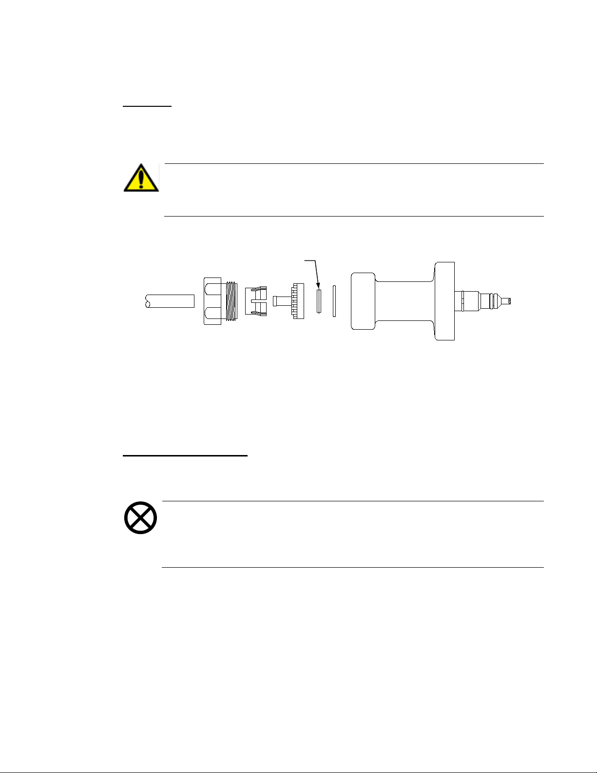
CONCENTRATE
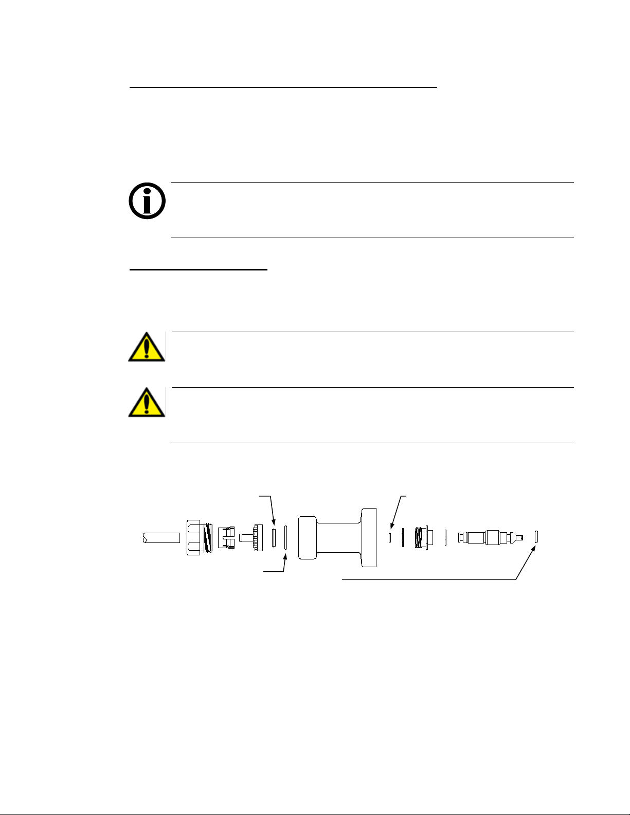
BICARBONATE CONNECTOR (BLUE): P/N F40007101 or 579072
3.0 ANNUAL (4000 HOUR) PREVENTIVE MAINTENANCE
FILTER INSERT P/N 566307
O-RING P/N 579092
O-RING P/N F40007100 OR 579070
RING
Perform the following Preventive Maintenance procedures every 12 months or
4000 hours of machine operation, whichever comes first. Perform the procedures in
the order given below to complete the Annual Preventive Maintenance.
Make copies of the Annual Preventive Maintenance Checklist provided at the back of
this manual and use them to record the maintenance done.
Note: When performing an Annual Preventive Maintenance do not perform
the six (6) month procedures first. The annual procedures will refer back to a
Section 2 six (6) month procedure when necessary.
3.1 FILTERS AND O-RINGS
Clean filters and replace O-rings as follows. Replace any filters that appear damaged
or corroded.
1. Inlet Water Filter in the inlet connector of the water supply (See Figure 2, pg. 9).
Warning! After cleaning or replacing the inlet filter screen, disinfect the
water inlet line as described in the Operator’s manual and in accordance with
your Unit Policy.
Warning! Excessive silicone-gel O-ring lubricant can damage the hydraulic
pressure transducers (P-DIAL and CFS). Only apply a minimal thin layer of
O-ring lubricant when needed.
2. Filters and O-rings in the concentrate (acid) and bicarbonate connectors
(See Figure 4). Replace all three O-rings in each connector.
O-
(ACID) CONNECTOR (RED): P/N F40007107 or 641759
Figure 4. Concentrate (Acid) and Bicarbonate Connector Assemblies.
3. Clean the Dialysate Inline filter (See Figure 2, pg. 9).
4. Replace the O-rings in the Dialysate Line Connectors (See Figure 2, pg. 9).
2008T Preventive Maintenance Procedures
P/N 508033 Rev. M
Page 18
Page 25

3.2 PRE-UF PUMP FILTER
Replace the Pre-UF Pump Filter (part number 672574 or M48341).
Caution: Do not attempt to disassemble the Pre-UF Pump Filter. If not
properly reassembled, the Pre-UF Pump filter may leak. A leak in the
hydraulic system at this location may affect the operation of the machine or
cause fluid loss from the patient.
3.3 UF PUMP CHECK VALVES
Caution: Ensure each check valve is oriented correctly to allow fluid flow in
the proper direction.
Replace the UF Pump Output check valves. There are two check valves at the UF pump
output. One is at the UF pump itself. The other is downstream at the UF Sample Port.
3.4 DIAPHRAGM PUMPS
For machines with diaphragm pumps equipped with extended life components3,
rebuild these pumps every 2 years or 8000 hours, whichever comes first. Otherwise,
rebuild the pumps annually or every 4000 hours, whichever comes first.
Rebuild the UF, bicarbonate and concentrate (acid) diaphragm pumps as described in
Sections 4.1 and 4.2.
3
Refer to Sections 4.1 and 4.2 o n how to recognize extended life pump components.
2008T Preventive Maintenance Procedures
P/N 508033 Rev. M
Page 19
Page 26

3.5 HEATER ELEMENT
For 2008T BlueStar Premium1 machines, this is an optional test.
Shock Hazard: Dangerous high voltage is present at these connections
when the machine is operating. Ensure the machine is disconnected from the
wall outlet.
Caution: The heater element is hot enough to inflict serious injury if it is
touched while power is applied or shortly after power is removed. Ensure the
machine is disconnected from the wall outlet.
1. Remove the rear access panels and distribution board cover so that the wires of
the heater are accessible.
Note: If the heater element is replaced, replace the heater O-ring as well
(part number F40007103 or 579075).
2. Remove the heater element from the hydrochamber on the machine (See Figure 2,
pg. 9). Inspect the heater element for signs of corrosion. If corrosion exists, replace
the heater element.
3. Attach one lead of the voltmeter to the ground (yellow / green wire) and the
other lead to the brown or blue wire. Measure the resistance. Resistance should
be “ OL “ or greater than 19.9 meg-ohms. If this is not the case, replace the
heater element.
4. After completing this check, reinstall the heater element and O-ring.
3.6 HIGH VOLTAGE AC CONNECTIONS
Perform the Six (6) Month Preventive Maintenance procedures in Sections 2.4.
1
Refer to Section 1.0 on how to recognize a 2008T BlueStar Pre mium ma chine .
2008T Preventive Maintenance Procedures
P/N 508033 Rev. M
Page 20
Page 27

3.7 DEAERATION MOTOR BRUSHES
Use marker to make hatch
marks to ensure proper
reassembling of motor
Motor Cap
Replace the deaeration motor brushes every 8000 hours using the following steps:
1. Remove the complete deaeration motor/pump assembly from the machine.
2. Using a marker, make marks on the motor housing and motor cap as
illustrated below. These marks will ensure the correct alignment when
reassembling the motor case.
Figure 5. Deaeration Motor/Pump Assembly with marks.
3. Using a T-25 Torx screwdriver, remove the two screws holding the motor
cap to the motor housing.
4. Remove the motor cap to gain access to the motor brushes. Replace the
motor brushes.
5. Reassemble the motor, aligning the marks.
6. While holding the pieces together, install and tighten the two T-25 screws.
Note: If the motor case and motor cap are not installed using the marks, the
motor will run in reverse and flow errors will result.
2008T Preventive Maintenance Procedures
P/N 508033 Rev. M
Page 21
Page 28

3.8 INLET WATER PRESSURE REGULATOR
Part Number
Verify that the regulator provides the proper water pressure as follows:
1. Shut off the water supply to the machine.
2. Install a pressure gauge with a T-fitting to monitor the pressure at the outlet
side of the Inlet Pressure Regulator (See Figure 2, pg. 9).
Caution: Use tie wraps or tubing clamps to secure the connections. The
water pressure may be sufficient to blow the lines off the fittings if they are not
secured.
3. Turn the water supply to the machine ON.
4. With the dialysate lines in the shunt, select2 Dialysis Mode. The pressure gauge
will cycle between two readings as the water inlet valve opens and closes.
5. Allow the water inlet valve to open and close for approximately 30 seconds
to clear any air.
6. Once the air is gone, verify the pressure gauge reads between 18 and 20psi
when the pressure is at its highest value, and reads greater than 8psi when
the pressure is at its lowest value.
Note: Readings below 8psi at the lowest level indicates inadequate inlet
water flow into the machine. This may be caused by a dirty inlet filter screen
or problems with the treated water supply.
7. Record the measured value on the Annual/4000 Hour Preventive
Maintenance Checklist.
8. Turn the dialysate flow off and the pressure gauge will stop cycling and will
show only a single pressure.
9. Note this single pressure reading on the pressure gauge.
10. After 15 minutes, check for any pressure increase on the pressure gauge.
11. If the pressure reading on the pressure gauge increases, the Inlet Pressure
Regulator is leaking internally and needs to be rebuilt or replaced
Complete Inlet Pressure Regulator: 565048
Rebuild Kit for the Inlet Pressure Regulator: 190934
12. If the Inlet Pressure Regulator passes the internal leakage test, turn the
machine OFF, turn OFF the water supply, remove the pressure gauge and
reconnect the tubing using clamps to prevent leaks.
13. Turn the treated water supply ON, turn the machine ON and select2 Dialysis
Mode. Start dialysate flow and inspect all hoses and connections. Ensure
that there are no leaks.
2
Refer to Section 1.4 on the use of screen buttons.
Page 22
2008T Preventive Maintenance Procedures
P/N 508033 Rev. M
Page 29

3.9 ONLINE CLEARANCE TEST (IF APPLICABLE)
If the machine is equipped with Online Clearance (OLC), conduct the following test:
OLC Self-Test
1. With stable temperature and conductivity, start an OLC Self-Test by
selecting2 the OLC Self-Test screen button on the Kt/V screen.
Note: Switch to the debug screens by pressing and holding the CTRL key on
the keyboard and then press the [▲] and [▼] keys at the same time for
approximately 1 sec. The main display will change indicating that the
machine is in debug mode.
2. When the OLC Self-Test is complete, go to debug screen #5 and confirm that
0 Test is in the range ±20.
Note: If 0 Test is out of range, the OLC Self-Test will fail. If this happens,
conduct temperature (PRE & POST) and conductivity calibrations, then
conduct OLC Self-Test again.
OLC Self-Test Troubleshooting
If the OLC Self-Test continues to fail after conducting the temperature (PRE &
POST) and the conductivity calibrations, conduct the following troubleshooting steps:
1. Turn the machine ON and allow the machine to run in Dialysis Mode at
500ml/min flow rate for approximately 10 minutes. This allows the
machine to come up to temperature and conductivity.
2. Once the machine is warmed up, remove X3 (MON-NTC) and X7 (COND)
from the distribution board.
3. Using the Resistor Plug Set for OLC Testing (part number 190168), plug the
6.04KΩ plug into X3 (MON-NTC) and the 274Ω plug into X7 (COND) on the
distribution board.
Note: Due to the resistor placement inside the OLC test plugs, the orientation
of the plug when inserted onto the distribution board is irrelevant.
2
Refer to Section 1.4 on the use of screen buttons.
2008T Preventive Maintenance Procedures
P/N 508033 Rev. M
Page 23
Page 30

4. Switch to the debug screens by pressing and holding the CTRL key on the
keyboard and then press the [▲] and [▼] keyboard keys at the same time for
approximately 1 sec. The main display will change indicating that the machine
is in debug mode.
5. Use the [▲] and [▼] keys to go to debug screen #5.
6. On debug screen #5, locate TPRE and observe its value for 1 minute. During this time, record the highest and lowest values observed in the table below.
Highest Value Lowest Value Difference
TPRE - =
7. Calculate the difference between the highest and lowest TPRE value and
record it in the table above.
8. Verify that the difference for TPRE ≤ 2. If the difference for TPRE > 2,
then possible causes are sensor board, motor noise, or -12V problems.
9. Again on debug screen #5, locate CPRE and observe its value for 1 minute.
During this time record the highest and lowest values observed in the table
below.
Highest Value Lowest Value Difference
CPRE - =
10. Calculate the difference between the highest and lowest CPRE value and
record it in the table above.
11. Verify that the difference for CPRE ≤ 8. If the difference for CPRE > 8,
then possible causes are sensor board, motor noise, or -12V problems.
12. Remove the 6.04KΩ and 274Ω plug from the distribution board and replace
the original connectors
13. Remove X44 (NTC-POST) and X13 (COND-POS) from the distribution
board.
14. Using the Resistor Plug Set for OLC Testing (part number 190168),
plug the 6.04KΩ plug into X44 (NTC-POST) and the 274Ω plug into
X13 (COND-POS) on the distribution board.
Page 24
2008T Preventive Maintenance Procedures
P/N 508033 Rev. M
Page 31

15. On debug screen #5, locate TPOS and observe its value for 1 minute.
During this time record the highest and lowest values observed in the
table below.
Highest Value Lowest Value Difference
TPOS - =
16. Calculate the difference between the highest and lowest TPOS value and
record it in the table above.
17. Verify that the difference for TPOS ≤ 2. If the difference for TPOS > 2, then
possible causes are sensor board, motor noise, or -12V problems.
18. Again on debug screen #5, locate CPOS and observe its value for 1 minute.
During this time record the highest and lowest values observed in the table
below.
Highest Value Lowest Value Difference
CPOS - =
19. Calculate the difference between the highest and lowest CPOS value and
record it in the table above.
20. Verify that the difference for CPOS ≤ 8. If the difference for CPOS > 8, then
possible causes are sensor board, motor noise, or -12V problems.
Note: In the following step, conduct the test for the dialysate flow ON to
OFF transition.
21. With the 6.04KΩ plug on X44 (NTC-POST) and the 274Ω plug on X13
(COND-POS) of the distribution board, verify that CPOS does not change
more than 10 increments when the dialysate flow is turned OFF.
22. Remove the 6.04KΩ and 274Ω plug from the distribution board and replace
the original connectors.
23. With stable temperature and conductivity, start an OLC Self Test by
selecting2 the OLC Self-Test screen button on the Kt/V screen.
24. When the OLC Self Test is complete, go to debug screen #5 and confirm
that 0 Test is in the range ±20.
2
Refer to Section 1.4 on the use of screen buttons.
2008T Preventive Maintenance Procedures
P/N 508033 Rev. M
Page 25
Page 32

3.10 DEAERATION AND LOADING PRESSURE
feet
mmHg
inches of Hg
0
760
-24.0
4000
639
-20.0
5000
612
-19.0
6000
585
-18.5
7000
561
-17.5
8000
537
-16.9
9000
514
-16.2
10000
492
-15.5
Verify that the deaeration pressure is between –24 and -25 inHg and the loading
pressure is between 18 and 20psi (between 23 and 25psi if a DIASAFE Plus filter
system is installed) as follows:
1. With dialysate flow OFF, install a pressure gauge with a T-fitting to monitor the
pressure on the inlet (suction) side of the deaeration pump (See Figure 2, pg. 9).
2. Connect a pressure gauge equipped with a yellow connector into the red
ACETATE/ACID port.
3. In Dialysis Mode, turn dialysate flow ON and verify that the pressure gauge
on the deaeration pump indicates between -24 and -25 inHg. The needle
will be vibrating somewhat. Verify that it does not go higher than -24 inHg
or lower than -25 Hg. Verify that the pressure gauge in the
ACETATE/ACID port indicates between 18 and 20psi (between 23 and
25psi if a DIASAFE Plus filter system is installed).
4. Record the measured values on the Annual/4000 Hour Preventive
Maintenance Checklist.
Note: When the machine is at a different elevation above sea level, it may be
difficult or impossible to achieve -24inHg. The following table will help in
determining the appropriate deaeration pressure calibration point at different
elevations:
Table 2
Approx.
Elevation
1000 728 -23.0
2000 697 -22.0
3000 667 -21.0
atmospheric
pressure
Minimum target deaeration
pressure relative to
atmospheric pressure
Page 26
2008T Preventive Maintenance Procedures
P/N 508033 Rev. M
Page 33

3.11 FLOW RELIEF PRESSURE
Verify that the flow relief pressure is between 29 and 30psi (between 35 and 36psi if a
DIASAFE Plus filter system is installed) as follows:
1. Turn the machine on in Service mode. From the Calibrate Hydraulics
screen, select2 the Flow Pressure screen button. The screen will change to
the following:
2. Connect a pressure gauge in line at the output of the flow pump (See Figure 2,
pg. 9).
Note: The output side of the flow pump is the side with the white reinforced
jacket over the line. The input side has clear plastic line.
3. Press the [CONFIRM] key to start the flow pump.
4. Verify the pressure gauge indicates a pressure between 29 and 30psi
(between 35 and 36psi if a DIASAFE Plus filter system is installed).
5. Record the measured value on the Annual/4000 Hour Preventive
Maintenance Checklist.
2
Refer to Section 1.4 on the use of screen buttons.
2008T Preventive Maintenance Procedures
P/N 508033 Rev. M
Page 27
Page 34

3.12 CONCENTRATE (ACID) AND BIC ARBONATE PUMPS
For 2008T BlueStar Premium1 machines, this is an optional test unless the pumps were
rebuilt.
Test the concentrate (acid) and bicarbonate diaphragm pumps as described in Section 4.3.
3.13 UF PUMP
Calibrate the UF Pump Volume (Refer to the 2008T Calibration Procedures – part
number 508032.)
Record the measured value on the Annual/4000 Hour Preventive Maintenance Checklist.
3.14 CONDUCTIVITY
Verify that the dialysate conductivity measured by the internal cell in the machine agrees
with an external conductivity meter within 0.1mS/cm as described in Section 2.6.
3.15 TEMPERATURE
Verify that the dialysate temperature shown on the front panel Display screen agrees
with an external temperature meter within 0.3°C at 37°C and 39°C as described in
Section 2.7
3.16 VOLT HI LO DETECT
For 2008T BlueStar Premium1 machines, this is an optional test.
Verify that the 5-volt supply is operating within 0.2 volts as reported on the debug
screen as follows:
1. Switch to the debug screens by pressing and holding the CTRL key on the
keyboard and then press [▲] and [▼] keyboard keys at the same time for
approximately 1 sec. The main display will change indicating that the
machine is in debug mode.
2. Use the [▲] and [▼] keys to go to debug screen #4.
3. Locate the 5V value on the display screen. This value must be between
4.8V and 5.2V.
Note: If the 5V value is not within limits, the problem is most likely the
12volt supply out of tolerance. Perform the Volt Hi Lo Detect calibration
procedure. Refer to the 2008T Calibration Procedures – part number 508032.
4. Record the measured value on the Annual/4000 Hour Preventive
Maintenance Checklist.
1
Refer to Section 1.0 on how to recognize a 2008T BlueStar Pre mium ma chine .
2008T Preventive Maintenance Procedures
P/N 508033 Rev. M
Page 28
Page 35

3.17 BLOOD LEAK AND DIMNESS
For 2008T BlueStar Premium1 machines, this is an optional test.
Verify that the blood leak level is between 4.5 and 5.2 volts and the blood dimness
level is within 5.0 ±1.0 volts as follows:
1. Switch to the debug screens by pressing and holding the CTRL key on the
keyboard and then press [▲] and [▼] keyboard keys at the same time for
approximately 1 sec. The main display will change indicating that the
machine is in debug mode.
2. Use the [▲] and [▼] keys to go to debug screen #4.
3. Locate the LEAK value on the display screen. This value must be between
4.5V and 5.2V.
4. Locate the DIMN value on the display screen. This value must be between
4.0V and 6.0V.
Note: If these values are outside the limits given, perform a bleach rinse to
clean the glass detector tube inside the machine before considering other
repairs.
5. Record the measured values on the Annual/4000 Hour Preventive
Maintenance Checklist.
1
Refer to Section 1.0 on how to recognize a 2008T BlueStar Pre mium ma chine .
2008T Preventive Maintenance Procedures
P/N 508033 Rev. M
Page 29
Page 36

3.18 ARTERIAL, VENOUS AND TRANSMEMBRANE PRESSURE
For 2008T BlueStar Premium1 machines, this is an optional test.
ARTERIAL PRESSURE
1. Inspect the internal pressure transducer protector for contamination. If
contamination is found, replace the pressure transducer protector (part
number M30971) and remove and disinfect the pressure port with 1:100
bleach for a minimum of 15 minutes.
2. Open the arterial transducer port P
On the blood pump module to air
ART.
(atmospheric pressure). Verify that the Arterial Pressure bargraph
indicates 0.
3. Attach a syringe and a calibrated pressure meter to the P
T-fitting.
4. Push the syringe in to show a pressure of 200mmHg on the external pressure
meter. Verify that the Arterial Pressure bargraph indicates 200.
5. Switch to the debug screens by pressing and holding the [▲] and [▼] ke ys at
the same time for approximately 1 sec. The main display will change
indicating that the machine is in debug mode.
6. Use the [▲] and [▼] keys to go to debug screen #1 and locate the ART
value.
7. Increase the pressure to a range of 310 – 315mmHg. Clamp off the tubing
at the P
Port and monitor the debug ART value for 30 seconds. The
ART.
maximum allowable leakage is 2mmHg in 30 seconds.
1
Refer to Section 1.0 on how to recognize a 2008T BlueStar Pre mium ma chine .
Port using a
ART.
2008T Preventive Maintenance Procedures
P/N 508033 Rev. M
Page 30
Page 37

VENOUS PRESSURE
1. Inspect the internal pressure transducer protector for contamination. If
contamination is found, replace the pressure transducer protector (part
number 650158) and remove and disinfect the pressure port with 1:100
bleach for a minimum of 15 minutes.
2. Open the venous transducer port P
On the level detector module to air
VEN.
(atmospheric pressure). Verify that the Venous Pressure bargraph
indicates 0.
3. Attach a syringe and a calibrated pressure meter to the P
Port using a
VEN.
T-fitting.
4. Push the syringe plunger in to show 400mmHg on the external pressure
meter. Verify that the Venous Pressure bargraph indicates 400.
5. Switch to the debug screens by pressing and holding the [▲] and [▼] ke ys at
the same time for approximately 1 sec. The main display will change
indicating that the machine is in debug mode.
6. Use the [▲] and [▼] keys to go to debug screen #1 and locate the VEN
value.
7. Decrease the pressure to a range of 310 – 315mmHg. Clamp off the tubing
at the P
Port and monitor the debug VEN value for 30 seconds. The
VEN.
maximum allowable leakage is 2mmHg in 30 seconds.
2008T Preventive Maintenance Procedures
P/N 508033 Rev. M
Page 31
Page 38

TRANSMEMBRANE PRESSURE
1. With dialysate flow ON, ensure the dialysate lines are full of fluid and no
air is visible passing through the flow indicator.
2. Hang a four-way connector to the I.V. pole at normal dialyzer height.
3. Set dialysate flow to 500ml/min, then press the [CONFIRM] key.
4. Open the arterial (P
) and venous (P
ART.
) transducer ports to air
VEN.
(atmospheric pressure).
5. Turn the blood pump off.
6. Turn dialysate flow OFF, remove the dialysate lines from the shunt and
attach them to the connector. Close the shunt door.
Note: Filling the lines before removing them from the shunt will avoid
wetting the pressure meter transducer during the test.
7. Connect a 30cc syringe to one of the four-way connector outlets and a
calibrated pressure meter to the remaining outlet.
8. Switch to the debug screens by pressing and holding the CTRL key on the
keyboard and then press [▲] and [▼] keyboard keys at the same time for
approximately 1 sec. The main display will change indicating that the
machine is in debug mode.
9. Use the [▲] and [▼] keys to go to debug screen #1.
10. Use the syringe to set the pressure on the external pressure meter to
0mmHg. Calculate the dialysate pressure measured by the machine as
follows:
• Note the value shown for TMP on the display screen.
• Subtract the value shown for VEN on the display screen.
11. Verify that the calculated value is between +20 and -10mmHg.
12. Use the syringe to create a pressure of -250mmHg on the external pressure
meter.
13. Calculate the dialysate pressure measured by the machine again as
described in step 10. Verify that the calculated value is between
-230 and -260mmHg.
Page 32
2008T Preventive Maintenance Procedures
P/N 508033 Rev. M
Page 39

3.19 DIALYSATE FLOW
For 2008T BlueStar Premium1 machines, this is an optional test.
Verify the dialysate flow is within ±3% of the stated rate at 500ml/min as follows:
Note: All flow rates are controlled by the software. Testing the rate at
500ml/min verifies the accuracy of all rates.
1. In Dialysis Mode, turn the dialysate flow ON at 500ml/min. Verify that the
UF pump is OFF and the machine is out of bypass. Allow the dialysate flow
to run for 2 minutes, minimum, before continuing.
Note: Do not collect the spent dialysate from the drain hose in the next step.
The accuracy of the collection will be affected if not collected directly from
the drain port with the drain hose removed.
2. Collect spent dialysate from the drain port on the back of the machine (See
Figure 2, pg. 9) for exactly 1 minute. Verify that the amount collected is
between 485 and 515ml.
3. Record the measured value on the Annual/4000 Hour Preventive
Maintenance Checklist.
3.20 HEPARIN PUMP
For 2008T BlueStar Premium1 machines, this is an optional test.
If the machine is equipped with a heparin pump module, clean and test the pump as follows:
1. Remove the heparin pump module from the machine and wipe the lower
edge of the module and the heparin pump cabinet opening to remove any
residual disinfecting agent.
2. Reinstall the heparin pump into the machine cabinet. When installing the
module screws do not use a power screwdriver
3. Place the machine in Dialysis Mode and clear all alarms.
4. Select2 the Heparin screen button. On this screen select2 the Syringe button.
Use the [▲] and [▼] keys to select the syringe being used for this test and press
the [CONFIRM] key.
5. Select2 the Load Syringe button. Press the [CONFIRM] key and the
carriage will fully retract downward.
6. When the carriage has stopped, press the [Escape] key and clean the
carriage bar (See Figure 6).
1
Refer to Section 1.0 on how to recognize a 2008T BlueStar Pre mium ma chine .
2
Refer to Section 1.4 on the use of screen buttons.
2008T Preventive Maintenance Procedures
P/N 508033 Rev. M
Page 33
Page 40

7. Extend the syringe plunger past the 10ml mark. Install the syringe into the
SYRINGE BODY HOLDER
CARRIAGE BAR
CARRIAGE / PLUNGER
PLUNGER HOLDER
CARRIAGE
pump and latch the plunger handle into the carriage. If needed, squeeze the
carriage/plunger release lever to slide the carriage up to meet the plunger
handle. The syringe plunger should be at a position greater than 10ml.
RELEASE LEVER
Figure 6. Heparin Pump Module.
8. Select2 the Heparin Prime button. Press and hold the [CONFIRM] key.
The plunger will start moving towards the 10ml mark. Release the
[CONFIRM] key as soon as the syringe plunger is aligned exactly with the
10ml mark on the side of the syringe body.
9. Select2 the Bolus data button. Use the [▲] and [▼] keys to set a value of
5.0ml then press the [CONFIRM] key.
10. Select2 the Total Infused data button. Press the [0] (zero) key and then the
[CONFIRM] key.
11. Select2 the Infuse Bolus button. Press the [CONFIRM] key and start
timing the interval with the stopwatch.
2
Refer to Section 1.4 on the use of screen buttons.
2008T Preventive Maintenance Procedures
P/N 508033 Rev. M
Page 34
Page 41

12. When the pump stops, use the table below to verify the time to run a 5ml
B-D
10ml
29.0 – 30.0 seconds
Monoject
10ml (12ml)
24.5 – 25.5 seconds
Bolus is correct for the selected syringe type.
Type Syringe Size 5ml Bolus Time
Terumo 10ml (12ml) 24.0 – 25.0 seconds
13. Also, verify that the Total Infused data button reads 5.0 and that the
syringe plunger has moved to between 4.8 to 5.2 on the syringe scale.
14. Move the carriage all the way up to the end of its travel.
Note: Use the Heparin Pump Prime function to move the carriage to the end
of travel to ensure the screw gear stays fully engaged for the end of travel
alarm test.
15. Select2 the RATE data button. Use the [▲] and [▼] keys to set a value of
9.9ml/hr. then press the [CONFIRM] key.
16. Go to the HOME screen and start the Tx Clock. The green status lamp
above the LCD screen should light.
17. Verify that a HEPARIN PUMP ALARM is displayed on the status line
within 2 minutes.
Note: If the machine is not alarm free, another message of higher priority
may be displayed on the status line.
2
Refer to Section 1.4 on the use of screen buttons.
2008T Preventive Maintenance Procedures
P/N 508033 Rev. M
Page 35
Page 42

3.21 BLOOD PUMP
Clean and test the arterial blood pump module as follows:
1. Remove the blood pump rotor by opening the door, pulling out the handle
and turning the rotor 90 degrees
2. Clean the rollers with a cloth dampened only with water.
3. With the crank lever pulled out, locate and lubricate the crank lever retainer
ball. If the crank lever is hard to pull out, replace the crank lever retainer
assembly (part number 564301).
4. Without removing the plastic sleeve, inspect the solid guide post on all four
(4) tubing guides. The solid guide post should not be loose or bent. If any
of the solid guide posts are loose or bent, the rotor assembly needs to be
replaced (part number M30990).
Note: The plastic sleeve will make it feel like the solid guide post is loose.
When inspecting, pay close attention to the movement of the metal shaft.
5. Clean the inside of the blood pump housing with the damp cloth.
Compressed air may be used if it is available.
6. Remove the blood pump module from the machine and inspect the motor
gearbox. In heavy use, some oil may accumulate on the gearbox housing.
Wipe the housing clean.
7. Wipe the lower edge of the module and the blood pump cabinet opening to
remove any residual disinfecting agent.
8. Reassemble the blood pump module and reinstall it in the machine cabinet.
When installing the module screws do not use a power screwdriver.
9. Place the machine in Dialysis Mode and clear all blood alarms.
10. Start the blood pump if it is not already running.
11. Open the blood pump door. Verify that the red alarm light on the blood
pump module lights within 15 or 30 seconds.
Note: Delay time before the blood pump alarm lights is set by dipswitch 4 on
the LP955 blood pump board.
2008T Preventive Maintenance Procedures
P/N 508033 Rev. M
Page 36
Page 43

12. Close the blood pump door and press the [RESET] key to clear the alarm.
Clamp
13. Test the pump as follows:
• Set the Tubing Size to 8mm.
• Insert a bloodline in the pump. Do not change the setting of the
tubing size selector, even if you are not using 8mm tubing.
• Connect a pressure gauge to the bloodline in the pump (See
Figure 7) and allow the rotor to pull up 37°C ± 1.5°C water. Let
this fluid flow past the pressure gauge long enough to clear out air.
Figure 7. Blood Pump Rotor Occlusion Test
• With the pump running at 600ml/min, clamp the outlet so that the
pressure gauge is between the output of the pump and the clamp
(See Figure 7). The peak pressure on the gauge must be between
25 and 35psi. If the peak pressure is out of range, replace the
blood pump rotor springs (part number 650174).
• Set the Tubing Size Selector to agree with the size of bloodline
used in the pump.
Page 37
2008T Preventive Maintenance Procedures
P/N 508033 Rev. M
Page 44

3.22 LEVEL DETECTOR
Caution: In the following steps, the level detector must be removed from the
machine cabinet. Before returning it to the cabinet, wipe the lower edge of the
module and the level detector cabinet opening to remove any residual
disinfecting agent. When installing the module screws do not use a power
screwdriver.
ALARM TEST
1. Perform Level Detector calibration per the procedure outlined in the 2008T
Calibration Procedures (part number 508032).
2. Place the machine in Dialysis Mode and turn the blood pump ON. Insert a
water filled venous chamber into the level detector and clear all alarms.
3. Position the Level Detector so you can watch the Channel 1 and Channel 2
LED's on the circuit board (See Figure 8 on page 39).
4. While watching the Channel 1 and Channel 2 LED's, remove the venous
chamber to create a blood alarm and close the occlusion clamp. Verify that
the Channel 1 LED lights first followed quickly by Channel 2.
OCCLUSION CLAMP TEST
1. Place a venous line into the closed occlusion clamp. Do not connect this
line to the venous chamber in the level detector.
2. Place the lower end of the venous line below the occlusion clamp in a
container of water positioned so that air escaping from the end of the line is
easily seen.
2008T Preventive Maintenance Procedures
P/N 508033 Rev. M
Page 38
Page 45

3. Connect a syringe and a pressure gauge to the venous line above the
RELAY TEST LED’S
CHANNEL 1 LED
CHANNEL 2 LED
TP3 (GROUND)
X153 ON LP450
occlusion clamp.
4. With the syringe, apply a pressure of at least 30psi (1550mmHg) to the
venous line while watching the end of the venous line in the water.
5. Verify that no air escapes from the venous line, indicating that the clamp is
fully occluding the line.
LIGHTS FIRST
LIGHTS SECOND
D19 & D6 ON LP450
BOARD
Figure 8. Level Detector Module.
2008T Preventive Maintenance Procedures
P/N 508033 Rev. M
Page 39
Page 46

RELAY CONTACT TEST
A relay prevents the level up and level down membrane keys on the face of the
level detector to function if they are pressed at the same time. These relay
contacts can be checked using the following steps:
1 With the machine in Dialysis Mode and the blood pump turned ON. Insert a
water filled venous chamber into the level detector and clear all alarms
2 Locate the relay test LED’s D6 and D19 on the LP450 board (see Figure 8).
3 To test the LED’s, press the level down switch on the face of the level detector
and verify that both LED’s D6 and D19 light. The on-board air pump will also
run. If both LED’s light, proceed to step 4.
Note: If either LED doesn’t light during the LED test (step 3), then the
results of the Relay Contact Test (step 4) are invalid. In this case use the
appropriate step below instead of step 4:
While in alarm condition (clamp closed), attach the ground lead of a voltmeter
to TP3 (ground) on the LP450 board. Measure the voltage on the solder side
of pins 1 and 2 of X153 on the LP450 board. Verify that both pins are 0 volts.
If voltage is present, the relay contacts are bad.
4 To test the relay contacts, remove the venous chamber to create a blood alarm
and verify that both LED’s D6 and D19 do not light when the level down
switch is pressed. If either LED lights, the relay contacts are bad.
3.23 ALARM OPERATION AND PRESSURE HOLDING TE STS
For 2008T BlueStar Premium1 machines, this is an optional test.
Perform the Six (6) Month Preventive Maintenance procedures in Section 2.8.
3.24 VERIFY pH
For 2008T BlueStar Premium1 machines, this is an optional test.
1. Place the machine into dialysis mode and allow it 10 minutes to stabilize.
2. Use a pH test strip (part number 335130-01 or equivalent) to verify the
dialysate fluid is between the ANSI/AAMI RD52 standard of 6.9 and 7.6.
3. Record the measured value on the Annual/4000 Hour Preventive
Maintenance Checklist.
1
Refer to Section 1.0 on how to recognize a 2008T BlueStar Pre mium ma chine .
2008T Preventive Maintenance Procedures
P/N 508033 Rev. M
Page 40
Page 47

3.25 RINSE CHECKS
Perform the Rinse Checks as follows:
1. Place the machine in rinse mode, then turn the water supply off. Verify that
the display screen shows NO WATER.
2. Turn water supply on
3. Start rinse mode, and watch the flow from the drain line. The water from
the drain line will stop at one point for 15 seconds. At this time put the
drain line in a 1000ml graduated cylinder. Start timing when the flow starts
again. At 30 seconds, remove the line from the graduated cylinder. Verify
that a minimum of 310ml is collected.
4. Record the measured value on the Annual/4000 Hour Preventive
Maintenance Checklist.
5. To avoid problems with pre-rinse, allow the rinse to complete prior to
proceeding to the next step.
6. Open the shunt door and remove the dialysate lines.
7. Connect the dialysate lines to an external temperature meter capable of
reading at least 85°C.
8. Close the shunt door.
9. Start the machine in heat disinfect mode with the dialysate lines on the
external temperature meter as follows:
• With the shunt door closed, reach up into the opening at the bottom of the
shunt and find the two spring-loaded switches that protrude through the
holes next to the connectors. Push these switches in with your fingers,
simulating dialysate lines connected to the shunt.
• While holding these switches pushed in, select2 the Heat Disinfect
button on the startup screen.
• While holding the switches, open the shunt door. Verify the heat
disinfect does not get interrupted.
• Leave the shunt door open; closing it will stop the heat disinfect mode.
2
Refer to Section 1.4 on the use of screen buttons.
2008T Preventive Maintenance Procedures
P/N 508033 Rev. M
Page 41
Page 48

Warning! Scalding hot water is passing through the dialysate lines and the
external meter manifold. Allow the dialysate lines and the external
temperature meter manifold to cool before disconnecting the lines.
10. The heat disinfect timer will not be operating. It is not needed. Monitor the
external temperature meter and verify that the temperature rises to between
80°C and 90°C.
Note: Some external temperature meters may not display correctly at higher
temperatures. Consult the appropriate product literature from the meter
manufacturer for applicable conversion charts.
11. Record the measured value on the Annual/4000 Hour Preventive
Maintenance Checklist.
3.26 POWER FAIL U R E AL ARM AND BATTERY REPLACEMENT
Remove the 9-volt battery located behind the monitor unit (See Figure 2, pg. 9). The
battery is inside the plastic housing. Press the cover in and to the left to release it,
then pull it out.
Note: If the 9-volt battery is swollen, the power logic board is bad and should
be replaced.
With the battery removed, perform an Alarm Test and confirm the Battery Test fails.
Note: If the Battery Test passes with the 9-Volt battery removed, IC9 is bad
on the Power Logic Board and should be replaced.
Replace the 9-volt battery with a new one observing the correct polarity marked
inside the holder. Install the battery/holder assembly into the monitor unit.
With the new battery in place, perform an Alarm Test and confirm the Battery Test
passes.
Test the power failure alarm by removing the machine power plug from the wall
outlet with the machine powered on. Verify that the audible alarm sounds.
2008T Preventive Maintenance Procedures
P/N 508033 Rev. M
Page 42
Page 49

3.27 BLOOD PRESSURE MODULE
Note: There are seven types of blood pressure modules that can be connected
to the 2008T. Since each module type has different test criteria and the 2008T
is unable to detect which module is connected, disregard the displayed
Pass/Fail results if present and use the appropriate table to determine pass or
fail.
Test the blood pressure module (See Figure 2, pg. 9), as follows:
Place the machine in Service Mode.
Select2 the Test BP Module button and the screen will change.
INFLATION SPEED TEST
From the Test BP Module screen, select2 the Inflation Speed button.
1. Connect the 10 foot blood pressure tubing from the module to the 700cc
port on the Dummy Cuff. Ensure the tubing fits snugly on the ports.
2. Press the [CONFIRM] key. The screen will change and the test will start.
3. The blood pressure module will pressurize the Dummy Cuff and report the
time. When the test is complete, use the table below to verify that the Time
to 250 value is within range dependent upon the module type installed.
Module Type Time to 250
M400 ≤ 7.3 seconds
M2000, M2600 or M3600 ≤ 10.0 seconds
TM-2910 or TM-2915 ≤ 10.0 seconds
SunTech ≤ 11.0 seconds
4. Press the [CONFIRM] key.
2
Refer to Section 1.4 on the use of screen buttons.
2008T Preventive Maintenance Procedures
P/N 508033 Rev. M
Page 43
Page 50

DEFLATION SPEED TEST
Note: The deflation speed test is not applicable to the SunTech module.
From the Test BP Module screen, select2 the Deflation Speed button.
1. Connect the 10 foot blood pressure tubing from the module to the 220cc
port on the Dummy Cuff. Ensure the tubing fits snugly on the ports.
2. Press the [CONFIRM] key. The screen will change and the test will start.
3. The blood pressure module will depressurize (deflate) the Dummy Cuff.
The screen will change and report the deflation speed at various pressures in
mmHg per second.
4. Use the table below to verify that the values reported are within the
following ranges dependent upon the module type installed.
Pressure
Model Type
M400 4.3 6.2 4.6 6.2 3.3 5.2 2.6 4.4
M2000 or M2600 4.4 6.7 4.4 6.7 3.0 5.2 2.4 4.6
M3600 3.8 6.6 3.8 6.6 2.8 5.5 2.3 4.6
TM2910 or TM-2915 3.5 7.5 3.5 7.5 3.5 7.5 3.5 7.5
SunTech N/A N/A N/A N/A N/A N/A N/A N/A
RATE AT 240
(mmHg/sec)
Min Max Min Max Min Max Min Max
RATE AT 160
(mmHg/sec)
RATE AT 80
(mmHg/sec)
RATE AT 40
(mmHg/sec)
5. Press the [CONFIRM] key.
AIR LEAKAGE TEST
From the Test BP Module screen, select2 the Air Leakage button.
1. Connect the 10 foot blood pressure tubing from the module to the
appropriate module specific port on the Dummy Cuff (see table at the top of
the next page). Ensure the tubing fits snugly on the ports.
2. Press the [CONFIRM] key. The screen will change and the test will start.
3. The blood pressure module will pressurize the Dummy Cuff as indicated by
a rise in the Cuff Pressure displayed to approximately 290mmHg. An
internal timer is then activated automatically. Any change in the pressure
being held will show in the Cuff Pressure display.
2
Refer to Section 1.4 on the use of screen buttons.
Page 44
2008T Preventive Maintenance Procedures
P/N 508033 Rev. M
Page 51
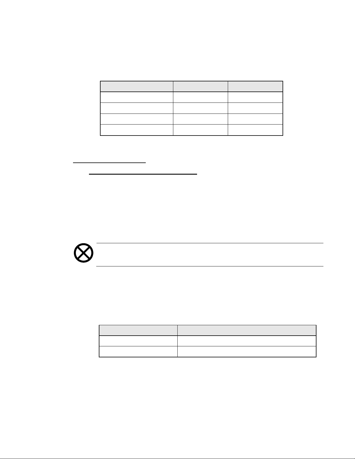
4. At the end of the Air Leakage test, the pressure is automatically released,
the screen will change and the Leak Rate in mmHg is displayed.
5. Use the table below to verify that the Leak Rate value is within range
dependent upon the module type installed.
Module Type Dummy Cuff Port Leak Rate
M400, M2000 or M2600 220cc
M3600 220cc
TM-2910 or TM-2915 700cc
SunTech 700cc
≤15mmHg
≤12mmHg
≤30mmHg
≤22mmHg
6. Press the [CONFIRM] key.
CALIBRATION CHECK
For the M400, TM-2910 & TM-2915
1. From the Test BP Module screen, select2 the Calibrate Mode button.
2. Disconnect the 10 foot blood pressure tubing from the Dummy Cuff and
connect it to a calibrated pressure meter accurate to within 1mmHg.
3. Press the CONFIRM key. The screen will change and the blood pressure
module will pressurize the line.
4. When the pressure shown on the display screen an on the external pressure
meter stabilizes, verify that they agree within 3mmHg.
Caution: Do not exceed 330mmHg in the following step. The blood
pressure module may be damaged if this pressure is exceeded.
5. Over-Pressure Relief Check:
Remove the hose from the external pressure meter and connect it to a large
syringe (60cc) that has its plunger pulled back. Use the syringe to overpressurize the blood pressure module while watching the display carefully.
Use the table below to verify that the pressure is automatically released
within range dependent upon the module type installed.
Module Type Over-Pressure Release Range
M400 between 320 and 330mmHg
TM-2910 and TM-2915 between 310 and 330mmHg
2
Refer to Section 1.4 on the use of screen buttons.
2008T Preventive Maintenance Procedures
P/N 508033 Rev. M
Page 45
Page 52

For the M2000, M2600, M3600 & SunTech
1. From the Test BP Module screen, select2 the Air Leakage button.
2. Disconnect the 10 foot blood pressure tubing from the blood pressure module.
3. Using a T-fitting, connect the blood pressure module, calibrated pressure
meter accurate to within ±1mmHg and to the appropriate module specific port
on the Dummy Cuff. (See the table below). Ensure the tubing fits snugly at
all connections.
Module Type Dummy Cuff Port
M2000, M2600 or M3600 220cc
SunTech 700cc
4. Press the CONFIRM key. The screen will change and the blood pressure
module will pressurize the line.
5. The blood pressure module will pressurize as indicated by a rise in the Cuff
Pressure displayed to approximately 290mmHg. An internal timer is then
activated automatically.
6. When the pressure shown on the display screen and on the external pressure
meter stabilizes, verify that they agree within 3mmHg.
7. At the end of the Air Leakage test, the pressure is automatically released.
8. Disconnect the tubing from the blood pressure module and reconnect the
10 foot blood pressure tubing.
9. Over-Pressure Relief Check:
Caution: Due to the microprocessor control of the M2000, M2600, M3600
and SunTech module, the over-pressure relief check does not need to be
conducted. An over-pressure relief test could permanently damage the
module.
2
Refer to Section 1.4 on the use of screen buttons.
2008T Preventive Maintenance Procedures
P/N 508033 Rev. M
Page 46
Page 53
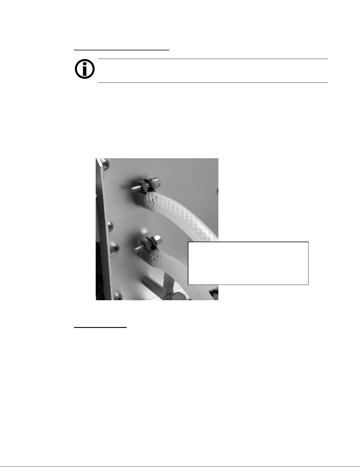
3.28 INSPECT DIALYSATE LINES
M43613
Note: During the following inspection, remove one dialysate line at a time to
avoid the potential of interchanging the connection points.
Every 8000 hours, inspect both dialysate lines at the point they connect to the back
of the machine (see Figure 9). Remove the tubing clamp from the upper dialysate
line connection and remove the tubing from its port. Inspecting inside and outside of
the tubing for damage. If damage is found and there is adequate tubing, cut the
tubing back at least one inch to remove the damaged tubing. Reconnect the dialysate
line to its port and securely re-clamp. If there is inadequate tubing to cut, replace the
tubing assembly; part numbers are listed in Figure 9. Repeat this process on the
lower dialysate line. Repair or replaced as needed.
3.29 FINAL CHECKS
1. Check the machine for any optional components that are not included here.
Perform the preventive maintenance tests provided with those units.
2. Perform the Six (6) Month Preventive Maintenance procedures in
Section 2.11.
Blue Dialysate Tubing Assembly
M43612
Red Dialysate Tubing Assembly
Figure 9
2008T Preventive Maintenance Procedures
P/N 508033 Rev. M
Page 47
Page 54

4.0 REBUILDING THE DIAPHRAGM PUMPS
The machine contains two types of diaphragm pumps. The ultrafiltration (UF) pump
is a solenoid coil type. The concentrate (acid) and bicarbonate pumps are stepper
motor types.
4.1 REBUILDING THE ULTRAFILTRATION PUMP
Figure 10 shows an exploded view of the ultrafiltration pump. When working on the
pump, be especially careful to do the following:
• Do not lose the wear button or the shim washers inside the pump solenoid.
• Count the shim washers when you disassemble the pump. The number of
washers varies as needed to mate the solenoid to the pump properly.
Caution: Replace exactly the same number of shims in the ultrafiltration
pump as were removed. The pump will not operate correctly if the same
number of shims are not replaced.
Examine all components for signs of corrosion. Replace any components that
show signs of excessive rust.
Note: If the UF pump does not provide output even though the green light is
on and not flashing, inspect the check valves. If a check valve is installed
backwards, the pump will not work.
2008T Preventive Maintenance Procedures
P/N 508033 Rev. M
Page 48
Page 55

INLET
OUTLET
INLET SEAL & SPRING
ASSEMBLY
SEALS
O-RINGS
P/N F40007099 or 579058
OUTLET SPRING
P/N 563025
(STRONGER)
INLET SPRING
P/N 565278
(WEAKER)
OUTLET PORT
(RED)
INLET PORT
(CLEAR)
OUTLET SEAL, SPRING
& SPACER ASSEMBLY
O-RINGS
P/N 579058
or F40007099
UF pump without extended life pump components
P/N 565279
UF pump with extended life components
Spring Set for UF-Pump (P/N 6 73945)
- Red Port (Outlet)
- Clear Port (Inlet)
- Seal & Spring Assembl y (Outle t)
- Seal & Spring Assembly (Inlet)
- O-Ring (qty 2)
Figure 10. Ultrafiltration Pump Exploded View.
Rebuild the ultrafiltration pump as follows:
1. Remove the UF pump from the machine (See Figure 2, pg. 9). Make a note
of which line goes to which port on the pump. When looking at the end
plate, the arrow pointing into the pump nozzle is the input side. The arrow
pointing away from the pump nozzle is the output side.
2. Hold the two sections of the pump housing and end plate together with one
hand and remove the four long screws from the end plate.
3. Carefully remove the end plate to reveal the input and output nozzles,
springs, seals and O-rings.
Caution: On machines with extended life pump components, the springs and
seals are preassembled components. If a seal or spring needs to be replaced,
replace the whole spring/seal assembly (see Figure 10).
2008T Preventive Maintenance Procedures
P/N 508033 Rev. M
Page 49
Page 56

4. Replace the inlet and outlet springs.
Caution: Be certain the correct springs are used. The weaker spring goes on
the inlet side. The stronger spring goes on the outlet side.
5. Inspect the seals. Replace them if there is any sign of swelling or wear.
6. Inspect the O-rings. Replace them if there is any sign of wear.
Note: Before reassembling the UF pump, verify nothing has fallen into the
solenoid opening.
7. Reassemble the pump as follows:
• The outlet seal goes toward the pump membrane.
• The inlet seal faces away from the pump membrane.
• Reinstall the spacer in the outlet nozzle if one was removed from the
pump.
• Ensure the outlet nozzle is oriented so it will be at the top of the pump
solenoid to help avoid air locks in the pump.
8. Replace the long screws into the end plate and tighten.
9. Replace the pump in the machine and reconnect the electrical and hydraulic
lines. Orient the pump so the outlet nozzle is above the inlet nozzle to help
avoid air locks.
10. To displace air and to check for leaks, start a rinse and allow the machine to
complete the entire rinse cycle.
11. Verify proper function of the UF pump by performing the Six (6) Month
Preventive Maintenance procedures in Section 2.5.
2008T Preventive Maintenance Procedures
P/N 508033 Rev. M
Page 50
Page 57
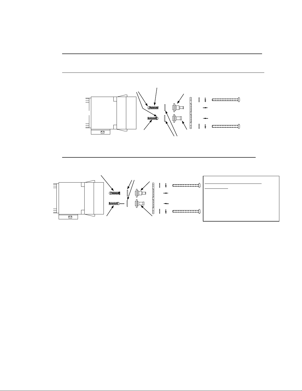
4.2 REBUILDING THE CONCENTRATE (ACID) AND BICARBONATE PUMPS
INLET
OUTLET
INLET
OUTLET
OUTLET SEAL, SPRING
& SPACER ASSEMBLY
INLET SEAL/PIN & SPRING
ASSEMBLY
SEALS
P/N 565279
INLET SPRING
OUTLET SPRING
P/N 565278
O-RINGS
P/N
F40007099
O-RINGS
P/N F40007099 or 579058
INLET PORT
P/N 6701
OUTLET PORT
(BLUE)
INLET PORT
(CLEAR)
OUTLET PORT
P/N 670
Figure 11 is an exploded view of the concentrate (acid) and bicarbonate pumps.
Concentrate (acid) and bicarbonate pumps without extended life pump components
770
P/N 565278
70
Concentrate (acid) and bicarbonate pumps with extended life pump components
579058 or
Spring Set for ACID/BIC-Pump
(P/N 674074)
- Blue Port (Outlet)
- Clear Port (Inlet)
- Seal & Spring Assembl y (Outle t)
- Seal/Pin & Spring Assembly (Inlet)
- O-Ring (qty 2)
Figure 11. Concentrate (acid) and Bicarbonate Pump Exploded View.
Rebuild the concentrate (acid) pumps as follows:
1. Remove the pump from the machine (See Figure 2, pg. 9). Make a note of
which line goes to which port on the pump. When looking at the end plate,
the arrow pointing into the pump nozzle is the input side. The arrow
pointing away from the pump nozzle is the output side.
2. Hold the two sections of the pump housing and end plate together with one
hand and remove the long screws that hold the end plate. On some models
of the pump, all four screws hold the end plate, and on others only two
screws hold the end plate.
If you removed all four screws to free the end plate, replace one or two of
them to avoid having the pump come completely apart. You only need
access to the inlet seals and springs.
2008T Preventive Maintenance Procedures
P/N 508033 Rev. M
Page 51
Page 58

3. Carefully remove the end plate to reveal the input and output nozzles,
springs, seals and O-rings.
Caution: On machines with extended life pump components, the springs and
seals are preassembled components. If a seal or spring needs to be replaced,
replace the whole spring/seal assembly. See Figure 11 on the previous page.
4. Replace the inlet and outlet springs.
5. Inspect the seals. Replace them if there is any sign of swelling or wear.
6. Inspect the O-rings. Replace them if there is any sign of wear.
7. Reassemble the pump as follows:
• The outlet seal goes toward the pump membrane.
• The inlet seal faces away from the pump membrane.
• Reinstall the spacer in the outlet nozzle if one was removed from the
pump.
• Ensure the outlet nozzle is oriented so it will be at the top of the pump
solenoid to help avoid air locks in the pump.
8. Replace the long screws into the end plate and tighten.
9. Reinstall the pump in the machine and reconnect the electrical and hydraulic
lines. Orient the pump so the outlet nozzle is above the inlet nozzle to help
avoid air locks.
Note: To avoid discoloration of the pump wiring, route the pump wiring
away from heat sources such as the pump housing and valve coils when
reinstalling the pump.
10. To displace air and to check for leaks, start a rinse and allow the machine to
complete the entire rinse cycle.
11. Test the rebuilt diaphragm pump by performing the procedure described in
Section 4.3.
2008T Preventive Maintenance Procedures
P/N 508033 Rev. M
Page 52
Page 59

4.3 TESTING CONCENTRATE (ACID) AND BICARBONATE PUMPS
The concentrate (acid) and bicarbonate pumps are tested by measuring the volume of
water they pump and comparing that measurement with the expected value
determined by the machine. The measured pump volume must be within 2% of the
expected value.
Test each pump as follows:
1. Place the machine in Dialysis Mode and open the shunt door.
2. Switch to the debug screens by pressing and holding the CTRL key on the
keyboard and then press [▲] and [▼] keyboard keys at the same time for
approximately 1 sec. The main display will change indicating that the
machine is in debug mode.
3. Use the [▲] and [▼] keys to go to debug screen #1.
• Locate the debug value for FILACT. In order to turn off dialysate flow
later, FILACT must be 0.
• Locate the debug value for DOUBLE. Certain types of Bicarbonate or
higher Bicarbonate levels selected will require the pump to double
stroke. If the debug value for DOUBLE is 1, the pump is double
stroking. Before continuing the test, adjust the Bicarbonate level until
the debug value for DOUBLE is 0.
• If the debug values for the Bicarbonate Pump Volume (BMIN and
BMAX) are showing 0 on debug screen #1, the machine is set up for a
concentrate (acid) family that does not use bicarbonate. Change the
concentrate (acid) selection to one requiring bicarbonate.
Note: The AMIN, AMAX, BMIN, BMAX are the expected limits for twenty
pulses of the concentrate (acid) pump volume and the bicarbonate pump
volume, respectively. These volumes are based on the measured volume of the
balancing chamber to produce the correct mixing ratio.
4. Stop the dialysate flow.
5. Connect a 25ml buret filled with water to the concentrate (acid) connector
for the pump to be tested. Use a short length of tubing forced over the end
of the connector, and make sure there are no leaks in the fitting to the
connector or to the buret.
2008T Preventive Maintenance Procedures
P/N 508033 Rev. M
Page 53
Page 60

6. With the machine in Dialysis Mode, start the dialysate flow. Observe that
liquid is drawn from the buret in discrete steps. Allow the machine to run
and pump fluid from the buret for about 20 strokes, to prime the pump.
Stop the dialysate flow.
Note: Do not let the buret run dry so that air can enter the system.
7. Refill the buret exactly to the full mark. Start the dialysate flow and count
exactly 20 pulses of water drawn from the buret, then stop the flow.
Note: If DOUBLE=1 on debug screen #1 then count each pulse of the double
stroking bicarbonate pump.
8. Measure the amount of water drawn from the buret carefully to within
0.05ml (within 1/2 division on a buret calibrated in 0.1ml increments).
Verify that this value is between the displayed limits of AMIN and AMAX
for the concentrate (acid) pump volume and BMIN and BMAX for the
bicarbonate pump volume.
9. If a pump volume falls outside of the permitted error, repeat the above
procedure to ensure that you are getting consistent results before recalibrating the machine.
Page 54
2008T Preventive Maintenance Procedures
P/N 508033 Rev. M
Page 61

NOTES:
___________________________________________________________________________________
___________________________________________________________________________________
___________________________________________________________________________________
___________________________________________________________________________________
___________________________________________________________________________________
___________________________________________________________________________________
___________________________________________________________________________________
___________________________________________________________________________________
___________________________________________________________________________________
___________________________________________________________________________________
___________________________________________________________________________________
___________________________________________________________________________________
___________________________________________________________________________________
___________________________________________________________________________________
___________________________________________________________________________________
___________________________________________________________________________________
___________________________________________________________________________________
___________________________________________________________________________________
___________________________________________________________________________________
___________________________________________________________________________________
___________________________________________________________________________________
___________________________________________________________________________________
___________________________________________________________________________________
___________________________________________________________________________________
___________________________________________________________________________________
Page 55
2008T Preventive Maintenance Procedures
P/N 508033 Rev. M
Page 62

PREVENTIVE MAINTENANCE CHECKLIST
SIX (6) MONTH
SERIAL NO. _________________________________________________DATE __________________________
MACHINE I.D. NO. ___________________________________________MACHINE HOURS ______________
TECHNICIAN(S) _____________________________________________LABOR HOURS _________________
See the Referenced Section of the 2008T Preventive Maintenance Procedures (part number
508033 Rev. M) for detailed instructions to perform the following:
Reference Section Procedure Value Completed By:
2.1 Clean Filters ........................................................................ (Replace If Necessary) ________
2.2 Inspect Pre-UF Pump Filter ..............................................
2.3 Inspect UF Pump Check Valves ........................................
2.4 Check High Voltage AC Connections..........................................
2.5 Calibrate UF Pump ........................................
2.6 Check Conductivity Calibration .................
(Range: 24 ± 0.1cc at 24 UF Pump strokes) ________ ________
(Range: Δ ± 0.1mS/cm) _________ ________ ________
(Replace If Necessary) ________
(Replace If Necessary) ________
(<0.2 ohms) ________ ________
Machine Display External Meter
2.7 Check Temperature Calibration.......................................... (Range: 37 ± 0.3°C) ________ ________
2.8 Check Alarm Operation and Pressure Holding Test
2.9 Verify pH
2.10 Check Power Failure Alarm
(N/A for 2008T BlueStar Premium) ............................................. (Range 6.9 to 7.6) ________ ________
(N/A for 2008T BlueStar Premium) ................................ ________
(Range: 39 ± 0.3°C) ________ ________
(N/A fo r 2008T BlueStar Premium) ________
2.11 Final Checks .............................................................................................. ________
NOTES:
___________________________________________________________________________________
___________________________________________________________________________________
___________________________________________________________________________________
___________________________________________________________________________________
___________________________________________________________________________________
___________________________________________________________________________________
___________________________________________________________________________________
___________________________________________________________________________________
___________________________________________________________________________________
Page 56
2008T Preventive Maintenance Procedures
P/N 508033 Rev. M
Page 63

NOTES:
___________________________________________________________________________________
___________________________________________________________________________________
___________________________________________________________________________________
___________________________________________________________________________________
___________________________________________________________________________________
___________________________________________________________________________________
___________________________________________________________________________________
___________________________________________________________________________________
___________________________________________________________________________________
___________________________________________________________________________________
___________________________________________________________________________________
___________________________________________________________________________________
___________________________________________________________________________________
___________________________________________________________________________________
___________________________________________________________________________________
___________________________________________________________________________________
___________________________________________________________________________________
___________________________________________________________________________________
___________________________________________________________________________________
___________________________________________________________________________________
___________________________________________________________________________________
___________________________________________________________________________________
___________________________________________________________________________________
___________________________________________________________________________________
___________________________________________________________________________________
Page 57
2008T Preventive Maintenance Procedures
P/N 508033 Rev. M
Page 64

PREVENTIVE MAINTENANCE CHECKLIST
ANNUAL/4000 HOUR
SERIAL NO. _________________________________________________DATE __________________________
MACHINE I.D. NO. ___________________________________________MACHINE HOURS ______________
TECHNICIAN(S) _____________________________________________LABOR HOURS _________________
See the Referenced Section of the 2008T Preventive Maintenance Procedures (part number
508033 Rev. M) for detailed instructions to perform the following:
Reference Section Procedure Value Completed By:
3.1 Clean Filters and Replace O-Rings .................................................................... __________
3.2 Replace Pre-UF Pump Filter ............................................................................... __________
3.3 Replace UF Pump Check Valves ........................................................................ __________
3.4 Rebuild UF, Concentrate (Acid) and Bicarbona te Pumps ............................... __________
(every 2 years or after 8000 hours if equipped with extended life pump components. Refer to Sections 1.0, 4.1 & 4.2)
3.5 Check Ground Heater Element (N/A for 2008T BlueStar Premium) ................................... __________
3.6 Check High Voltage AC Connections ...................................................
3.7 Replace Deaeration Motor Brushes ................................................
3.8 Check Inlet Water Pressure Regulator ........................................
3.9 Conduct Online Cleara nce Test ..........................................................
3.10 Check Deaeration Pressure ..............................................
Check Loading Pressure ....................
3.11 Check Flow Relief Pressure ..............
(Range: 18 to 20psi / with DIASAFE
(Range: 29 to 30psi / with DIASAFE
3.12 Test Concentrate (Acid) and Bicarbonate Pumps
3.13 Calibrate UF Pump ...............................................
3.14 Check Conductivity Calibration .........................
(Range: Δ ± 0.1mS/cm) _________ __________ __________
(Range: See Table 2 on page 26) __________ __________
®
®
(N/A unless the pumps were rebuilt) .... __________
(Range: 24 ± 0.1cc at 24 UF Pump strokes) __________ __________
3.15 Check Temperature Calibration ................................................... (Range: 37 ± 0.3°C) __________ __________
(Range: 39 ± 0.3°C) __________ __________
3.16 Check Volt Hi Lo Detect
(N/A for 2008T BlueStar Premium) .................. (Range: 4.8 to 5.2 ± 0.2V) __________ __________
3.17 Check Blood Leak Calibration (N/A for 2008T BlueStar Premium) ............... (Range 4.5 to 5.2V) __________ __________
Check Dimness Calibration
3.18 Check Arterial, Venous and TMP Calibration
3.19 Check Dialysate Flow
3.20 Check Heparin Pump
(N/A for 2008T BlueStar Premium) .................... (Range 4.0 to 6.0V) __________ __________
(N/A for 2008T BlueStar Premium) .......... __________
(N/A for 2008T BlueStar Premium) ............ (Range @ 500ml/min: 485 to 515ml) __________ __________
(N/A for 2008T BlueStar Premium) ................................... (If Applicable) __________
3.21 Check Blood Pump .............................................................................................. __________
3.22 Check and Calibrate Level Detector .................................................................. __________
3.23 Check Alarm Operation and Pre ss ure Holding Tests
3.24 Verify pH
(N/A for 2008T BlueStar Premium)................................................... (Range: 6.9 to 7.6) __________ __________
3.25 Rinse Check .............................................................................
(N/A for 2008T BlueStar Premium) __________
(Range: ≥ 310ml collected) __________ __________
Heat Disinfect Check ......................................................................
3.26 Check Power Failure Alarm ............................................................................... __________
Replace 9-Volt Battery ........................................................................................ __________
3.27 Check Blood Pressure Module ............................................................................ __________
3.28 Inspect Dialysate Lines ....................................................................
3.29 Final Checks ......................................................................................................... __________
(<0.2 ohms) __________ __________
(every 8000 hours) __________
(Range: 18 to 20psi) __________ __________
(If Applicable) __________
Plus filter 23 to 25psi) __________ __________
Plus filter 35 to 36psi) __________ __________
Machine Display External Meter
(Range: 80 to 90°C) __________ __________
(every 8000 hours) __________
2008T Preventive Maintenance Procedures
P/N 508033 Rev. M
Page 58
Page 65

NOTES:
___________________________________________________________________________________
___________________________________________________________________________________
___________________________________________________________________________________
___________________________________________________________________________________
___________________________________________________________________________________
___________________________________________________________________________________
___________________________________________________________________________________
___________________________________________________________________________________
___________________________________________________________________________________
___________________________________________________________________________________
___________________________________________________________________________________
___________________________________________________________________________________
___________________________________________________________________________________
___________________________________________________________________________________
___________________________________________________________________________________
___________________________________________________________________________________
___________________________________________________________________________________
___________________________________________________________________________________
___________________________________________________________________________________
___________________________________________________________________________________
___________________________________________________________________________________
___________________________________________________________________________________
___________________________________________________________________________________
___________________________________________________________________________________
Page 59
2008T Preventive Maintenance Procedures
P/N 508033 Rev. M
Page 66

1 Bar
29.53 inHg
1 inHg
25.4 mmHg
1 Psi
51.72 mmHg
1 FLUID OUNCE
29.6 MILLILITERS
1 U.S QUART
0.946 LITERS
1 U.S. GALLON
3.8 LITERS
0.034 FLUID OUNCES
1 MILLILITER
1.057 QUARTS
1 LITER
0.26 U.S. GALLON
1 LITER
1 OUNCE (avdp.)
28.35 GRAMS
1 POUND (avdp.)
0.45 KILOGRAM
0.035 OUNCE (avdp.)
1 GRAM
COMMON CONVERSIONS
PRESSURE
VOLUME
MASS
Page 67

http://www.fmcna.com
Fresenius Medical Care North America
Manufactured by:
Fresenius USA, Inc.
4040 Nelson Avenue
Concord, CA 94520
800 227-2572
 Loading...