

Page 1

2008®T
HEMODIALYSIS SYSTEM
TECHNICIAN’S
MANUAL
Part Number 490130 Rev. H
Fresenius Medical Care North America
920 Winter St.
Waltham, MA 02451
Manufactured by:
Fresenius USA, Inc.
4040 Nelson Avenue
Concord, CA 94520
http://www.fmcna.com
Copyright 2008 – 2017 Fresenius Medical Care, All Rights Reserved
Page 2

2008T Technician’s Manual
© Copyright 2008 – 2017 Fresenius Medical Care, All Rights Reserved
This document contains proprietary and confidential information of Fresenius USA, Inc. d/b/a Fresenius
Medical Care North America and its affiliates (“Fresenius Medical Care”). The contents of this document
may not be disclosed to third parties, copied, or duplicated in any form, in whole or in part, without the prior
written permission of Fresenius Medical Care.
Fresenius Medical Care, the triangle logo, 2008, Diasafe and bibag are trademarks of Fresenius Medical
Care Holdings, Inc., or its affiliated companies. All other trademarks are the property of their respec ti ve
owners.
Any questions, contact Technical Support at 800-227-2572
Page 3

TABLE OF CONTENTS
I SPECIFICATIONS
II HYDRAULIC DESCRIPTION
III ELECTRONIC CIRCUIT DESCRIPTION
IV MODULE DESCRIPTION
ADDITIONAL DOCUMENTATION*:
2008T OPERATOR’S MANUAL (P/N 490122)
2008T CALIBRATION PROCEDURES (P/N 508032)
2008T PREVENTIVE MAINTENANCE PROCEDURES BOOKLET (P/N 508033)
2008T HYDRAULIC FLOW DIAGRAMS (P/N 700078)
2008T ELECTRONIC BLOCK DIAGRAMS (P/N 290443)
2008T DEBUG SCREENS BOOKLET (P/N 490139)
2008T OPTIONS CONFIGURATOR INSTRUCTIONS (P/N 508635)
bibag® V2.0 TECHNICIAN’S MANUAL (P/N 490188)
* The latest revision of the additional documentation can be found at the following web location:
https://fmcna.com/product-support-documentation/
2008T Technician’s Manual – 490130 Rev. H i
Page 4
Section I – Specifications
Symbol
Description
Warning! A statement that identifies conditions or actions that could
SECTION I - SPECIFICATIONS
2008T HEMODIALYSIS MACHINE
Refer to the “Machine Specifications” section of the 2008T Operator’s Manual (P/N 490122)* for
the complete list of machine specifications for the 2008T Hemodialysis machine.
Conventions
and
result in personal injury or loss of life. Warnings found in this manual
outside of this section are designated with the warning symbol.
Note: Notes are advisory comments or recommendations regarding
practices or procedures.
* The latest revision of documentation can be found at the following web location:
https://fmcna.com/product-support-documentation/
2008T Technician’s Manual – 490130 Rev. H I-1
Page 5

Section I – Specifications
PRODUCT IMPROVEMENT POLICY
The 2008T Hemodialysis machine was designed and built to comply with the product specifications
outlined in the 2008T Operator’s Manual (P/N 490122). It is the intention of Fresenius Medical
Care North America to improve products continuously, a process which may result in modifications
to specifications or equipment produced in the future. Such product improvements shall not incur
any obligation to make similar changes or improvements to equipment previously produced. These
changes or improvements may or may not be applicable or usable with previously produced
equipment. Where possible, improvements will be made available at reasonable prices. Any such
improvements shall not be construed as corrections of any perceived deficiency.
In order to properly calibrate and maintain the 2008T Hemodialysis machine, the documentation
being used must be up to date. The current revision of a document can be obtained from the
Fresenius Medical Care Website at:
https://fmcna.com/product-support-documentation/
2008T Technician’s Manual – 490130 Rev. H I-2
Page 6

Section II – Hydraulic Description
SECTION II – HYDRAULIC DESCR IPTIO N
DESCRIPTION OF THE HYDRAULIC COMPONENTS
All valves and motors are supplied with 24V DC; the heater is supplied with 120V AC 60Hz;
thermistors, float switch, blood leak detector, pressure sensors and reed switches with 12V DC;
conductivity cell and level sensor with 12V AC at high frequencies;
Inlet filter screen
Prevents the 2008T Hemodialysis machine components from being obstructed (mounted in the inlet
water line).
Water inlet regulator
Limits the inlet water pressure.
Balancing chamber
The most important component for volumetric dialysate balancing; two spherical chambers
(30m1 each); 8 solenoid valves; two membranes reliable and proven hydraulic component from
A2008C/D/E/H series; guarantees accurate fluid balancing.
Hydrochamber
Consists of a heater including valve “39” and an orifice to provide sufficient volume to deaerate the
water; separates the air from the water and provides mounting for the loading pressure valve; control
NTC 2 (temperature sensor for temperature control circuit);
Function: warming water; provides air gap and a level sensor to maintain the water level.
Monitoring NTC 3
Function: independent temperature sensor for temperature monitoring.
Flow indicator
Optical flow indication and gross flow measurement.
Dialyzer valves V24, V25, and bypass valve V26
Bypasses (V24 closed, V25 and V26 open) the dialyzer and prevents exposure of the patient to
improper dialyzing fluid (temperature or conductivity alarm); the dialyzer can be isolated (V24 and
V25 closed, V26 open; i.e. for online pressure holding test or resetting a hardware TMP alarm
(i.e. adjusting TMP). For adjusting TMP, V24 closed, V25 and V26 open to serve as bypass.
Dialysate line safety interlock
2 switches for dialysate lines;
1 switch for bypass when shunt cover is open;
provides additional safety against inadvertently rinsing or disinfection;
defines dialyzer emptying program.
Dialyzer filter
Prevents hydraulic components from being obstructed; mounted outside 2008T Hemodialysis
machine; easy to service.
2008T Technician’s Manual – 490130 Rev. H II-1
Page 7

Section II – Hydraulic Description
Dialysate pressure transducer
Pressure transducer for dialysate pressure measurement; used as a sensor for the pressure holding
test. It is also used to switch the balancing chamber in rinse mode.
Blood leak detector
Color sensitive blood leak detector (temperature compensated), is able to distinguish between
opaque layers in the cell and real presence of blood in the dialyzing fluid.
Secondary air separation
Prevents air from entering the balancing chamber assuring precise weight removal; device contains
fluid level detector, air separation volume and valve V43.
Mixing chamber(s)
A cylindrical chamber that swirls the proportioned dialysate solution which provides for a complete
mixing prior to entering the balancing chamber.
Chamber Full Switch
Pressure transducer that senses pressure peak to switch the balance chamber.
Flow pump
DC motor driven gear pump;
Function: filling of the balancing chamber, spent side.
Deaeration pump
Provides deaeration and loading pressure.
Heat exchanger
Preheats inlet water by using the thermal energy in the spent dialysate.
Conductivity cells
Measures conductivity pre dialyzer. There are two conductivity cells, one pre dialyzer and one post
dialyzer.
UF pump
Responsible for fluid removal
Acid pump
Delivers acid proportioned by the microprocessor according to settings in the Dialysate Composition
Screen.
Bicarbonate pump
Delivers bicarbonate proportioned by the microprocessor according to settings in the Dialysate
Composition Screen.
Recirculation valve V29
Allows fluid to the drain to be diverted into the hydrochamber; used in heat disinfect to heat up
faster and to conserve energy.
2008T Technician’s Manual – 490130 Rev. H II-2
Page 8

Section II – Hydraulic Description
HYDRAULIC CONNECTION PANEL
TO DIALYZER - tubing to dialyzer (blue dialyzer quick connector)
FROM DIALYZER - tubing from dialyzer (red dialyzer quick connector)
WATER INLET - hose for water inlet
TO DRAIN - outlet hose to drain
GROUND - fixing screw for potential equalization
2008T Technician’s Manual – 490130 Rev. H II-3
Page 9

Section II – Hydraulic Description
HYDRAULIC OPERATION
1. Time constants
The overlap time (delay time) of the balancing chamber valves is always 50 ms. This time is
included in the switching time of the balance chamber (i.e., switching time is 6.00 seconds means a
5.95 second fill time plus a 50 ms delay time).
Time constants of the balance chamber.
Flow rate 100 ml/min t = 18.0 s ± 10%
Flow rate 200 ml/min t = 9.0 s ± 10%
Flow rate 300 ml/min t = 6.0 s ± 10%
Flow rate 400 ml/min t = 4.5 s ± 10%
Flow rate 500 ml/min t = 3.6 s ± 10%
Flow rate 600 ml/min t = 3.0 s ± 10%
Flow rate 700 ml/min t = 2.57 s ± 10%
Flow rate 800 ml/min t = 2.25 s ± 10%
2. Rinse
Rinse can only be started if the acid and bicarbonate connectors are in their rinse ports, the dialyzer
couplings are connected to the shunt, the shunt door is closed and there is no blood sensed.
During rinse the following occurs:
The UF pump runs at 4000 ml/h
V24 and V25 alternately open and close with the opening of V26 every balancing
chamber cycle.
V43 opens 6 out of 31 balancing chamber cycles.
V29 opens 3 out of 31 balancing chamber cycles.
The acid and bicarbonate pump stroke every balancing chamber cycle.
This pattern assures that all of the various parts of the hydraulics get adequately rinsed.
The rinse program lasts until it is stopped by the timer counting to 0 or by the operator. The
remaining time on rinse is displayed on the screen. If the remaining time is zero, the machine stops
the flow pump and displays a message “Press CONFIRM to exit” in the status box.
Note: The rinse time is selectable by the user in the Default Settings of Service Mode.
2008T Technician’s Manual – 490130 Rev. H II-4
Page 10

Section II – Hydraulic Description
Note: The Rinse time, selectable by the user in the Default Settings of Service Mode,
minutes, otherwise it displays 15 minutes.
3. Mandatory Rinse
A Mandatory Rinse has to always be performed after or interrupted Chemical Disinfection/Dwell
and/or Acid Clean. The user is informed by a message in the status box. The only difference
between Mandatory Rinse and a regular Rinse program is that the Mandatory Rinse has to run for a
predefined time and cannot be terminated.
If the machine is turned off or the acid or bicarbonate connectors are pulled during Mandatory Rinse
before the needed time is over, the machine comes up with Mandatory Rinse again after power on.
Mandatory Rinse can only be started if the acid and bicarbonate connectors are in their rinse ports,
the dialyzer couplings are connected to the shunt, the shunt door is closed and there is no blood
sensed.
During a Mandatory Rinse, the remaining time is displayed. If the remaining time is zero, the
machine stops and displays a message “Press CONFIRM to exit” in the status box.
is used to time the Mandatory Rinse. For Diasafe, if the Rinse time is greater than 15
4. Chemical Disinfection/Rinse
Chemical Disinfection/Rinse can only be started if the acid and bicarbonate connectors are in their
rinse ports, the dialyzer couplings are connected to the shunt, the shunt door is closed and there is no
blood sensed. When Acid Cleaning is started, the lines are rinsed and then prompts to attach the acid
and bicarbonate connectors to jug(s) containing an acid cleaner. The Chemical Disinfection/Rinse
procedure is followed immediately by a Post Rinse.
If the machine is turned off or the acid or bicarbonate connectors are pulled during Chemical
Disinfection/Rinse before the needed time was over, the machine comes up with Mandatory Rinse
after power on. During pulling acid, returning acid to its rinse port.
If the machine has performed any program other than rinse or heat disinfect before, the Chemical
Disinfection/Rinse program always starts with a pre-rinse for 7 minutes (or 10 minutes if Diasafe
Filter is selected in Hardware Options of Service Mode) to rinse out concentrate or any disinfectant.
The pre-rinse time is displayed on the screen.
After pre-rinse, the machine pulls in 120ml of disinfectant, the timer starts decrementing until it
reaches 0 and the cycle is finished. The pre-rinse, the time remaining, and the post-rinse times are
displayed on the screen. If the remaining time is zero, the machine prompts to connect the acid
connector into its rinse port and a Post Rinse will begin.
During the Post Rinse the remaining time is displayed. If the remaining time is zero, the machine
stops and displays a message “Press CONFIRM to exit” in the status box.
Note: The Chemical Disinfection/Rinse time is selectable by the user in the Default
Settings of Service Mode.
2008T Technician’s Manual – 490130 Rev. H II-5
Page 11

Section II – Hydraulic Description
5. Chemical Disinfection/Dwell
Chemical Disinfection/Dwell can only be started if the acid and bicarbonate connectors are in their
rinse ports, the dialyzer couplings are connected to the shunt, the shunt door is closed and there is no
blood sensed. When Acid Cleaning is started, the lines are rinsed and then prompts to attach the acid
and bicarbonate connectors to jug(s) containing an acid cleaner.
When the program is complete, if the machine is turned off or the acid or bicarbonate connectors are
pulled during Chemical Disinfection/Dwell before the needed time was over, the machine comes up
with Mandatory Rinse after power on. During pulling acid, returning acid to its rinse port.
If the machine has performed any program other than rinse or heat disinfect before, the Chemical
Disinfection/Dwell program always starts with a Pre-Rinse for 7 minutes (or 10 minutes if Diasafe
Filter is selected in Hardware Options of Service Mode) to rinse out concentrate or any disinfectant.
The Pre-Rinse time is displayed on the screen.
After Pre-Rinse, the machine pulls in 120ml of disinfectant, the timer starts decrementing until it
reaches 0 and the cycle is finished. The Chemical Dwell follows after a short delay. The Pre-Rinse
and time remaining times are displayed on the screen.
If the remaining time is zero the machine stops. Then the machine prompts to connect the acid
connector into its rinse port. The machine will run for about a minute to draw up disinfectant left in
the acid line and then will display the message “Press CONFIRM to exit” in the status box. A
Mandatory Rinse must be performed prior to using the machine.
Note: The Chemical Disinfection/Dwell time is selectable by the user in the Default
Settings of Service Mode.
6. Acid Clean
Acid Cleaning can only be started if the acid and bicarbonate connectors are in their respective rinse
ports, the dialyzer couplings are connected to the shunt, the shunt door is closed and there is no
blood sensed. When Acid Cleaning is started, the lines are rinsed and then prompts to attach the acid
and bicarbonate connectors to jug(s) containing an acid cleaner.
When the program is complete, if the machine is turned off or the acid or bicarbonate connectors are
inserted into their rinse ports during an Acid Cleaning before the needed time was over, the machine
comes up with Mandatory Rinse after power on.
If the remaining time is zero the machine stops and prompts to connect the acid and bicarbonate
connectors into their respective rinse ports. The machine will display the message “Press
CONFIRM to exit” in the status box. A Mandatory Rinse must be performed prior to using the
machine.
Note: The Acid Cleaning time is selectable by the user in the Default Settings of
Service Mode.
2008T Technician’s Manual – 490130 Rev. H II-6
Page 12

Section II – Hydraulic Description
7. Heat disinfect
Heat disinfect can only be started if the acid and bicarbonate connectors are in their rinse ports, the
dialyzer couplings are connected to the shunt and the shunt door is closed and blood is not sensed.
If the machine has performed any program other than rinse or heat disinfect before, the heat disinfect
program always starts with a Pre-Rinse for 7 minutes (or 20 minutes if Ext. Pre-Rinse is selected in
Default Settings of Service Mode or 10 minutes if Diasafe Filter is selected in Hardware Options of
Service Mode) to rinse out concentrate or any disinfectant. The Pre-Rinse time is displayed on the
screen.
After Pre-Rinse, the machine starts running in recirculation mode (V29 open and V30 closed).
When the water temperature reaches 80°C, the timer starts decrementing until it reaches 0 and the
cycle is finished. The Pre-Rinse time and time remaining are displayed on the screen. If the
predefined time has elapsed, the machine turns off all pumps and valves and displays the message
“Press CONFIRM to exit” in the status box or, if set, the machine will power off when heat
disinfection finishes.
Note: The Heat Disinfection time is selectable by the user in the Default Settings of
Service Mode.
8. Flow off
After the flow has been turned off, the heater is turned off and the deaeration pump will turn off after
one minute.
9. No program mode (Select Program screen)
In “no program state” everything is off except for the deaeration pump and V25, V26, V30, V31,
V32, V33 and V34 are on. All alarms are not active or displayed except for blood pressure alarms.
If blood is sensed there will be an audible alarm and a message in the display. The heater is disabled.
2008T Technician’s Manual – 490130 Rev. H II-7
Page 13

Section II – Hydraulic Description
10. Filling Program
The filling program is a special hydraulic program that runs when air is detected at level sensor #6.
The flow rate is reduced and valve 43 is open depending on dialysate pressure so that when the
pressure is high enough, air in the air separation chamber is sent down the drain. Unlike normal
balance chamber operation, the spent side of the balance chamber is not opened to the drain. Instead,
all dialysate put into the fresh side of the balance chamber is used to push air and any additional
dialysate down the drain through valve 43. The level sensor #6 (Air Sensor in Air Separation
Chamber) is only checked at the end of the cycle. If there is still air in the air separation chamber,
the next cycle is performed. If not, the machine will go on with dialysis. If the filling program
occurs and there are no water alarms, valves 24 and 25 are open and valve 26 is closed during the
filling program. UF is stopped during the filling program. If the filling program runs for more than
60 seconds with blood sensed, a permanent fill alarm will occur and the message “Fill Program
Alarm” is displayed in the status box.
11. Flow alarm
Flow alarm will occur if:
a. The float switch opens valve 41, and the water level is not up within the approximately 6
seconds, all balance chamber valves shut off, heater is off until the sensor detects water (“No
Water” message is displayed).
b. If the float switch does not detect a low level within 2.5 seconds after the balance chamber did
cycle (“Flow Inlet Error” message is displayed). Exception is recirculation. Heater off
c. The CFS (chamber full switch) does not switch the balance chamber for 10 seconds. Exception
is flow off and no program state. Heater off (“Flow Error” is displayed).
d. The CFS switches the chamber faster than 1.8 seconds. Heater off (“High Flow Error” is
displayed).
2008T Technician’s Manual – 490130 Rev. H II-8
Page 14

Section II – Hydraulic Description
DIALYSATE CIRCUIT
In the dialysate compartment, water and concentrate are mixed at the set ratio and then deaerated and
heated to desired temperature (range 35-39°C).
1. Water Inlet
Allowable incoming water pressure: 20 to 105 PSI. Water temperature must be a minimum of 10°C,
and a maximum of 25°C. The water must meet AAMI (Association for the Advancement of
Medical Instrumentation) standards for water for dialysis. Periodic maintenance and disinfection
procedures are required to maintain the water quality. Refer to the “Machine Specifications” section
of the 2008T Operator’s Manual (P/N 490122) for the water quality specifications.
2. Deaeration
The dialysate is deaerated by negative pressure created by the deaeration pump.
3. Heating
The 1300 watt heater adjusts the dialysate to the desired temperature. There is a control which
allows adjustment of the dialysate temperature between 35 and 39 °C. A heat exchanger is used to
recover the heat from the drain fluid.
4. Dialysate Balancing Chamber
The balance chambers assure that equal amounts of dialysate enter and exit the dialyzer. The UF
membrane pump withdraws extra fluid at a set rate. This causes a UF pressure or transmembrane
pressure (TMP), dependent on the dialyzer and the UF rate. The fluid withdrawn by the membrane
pump flows from the blood as ultrafiltrate. The function is described on the following pages.
2008T Technician’s Manual – 490130 Rev. H II-9
Page 15
Section II – Hydraulic Description
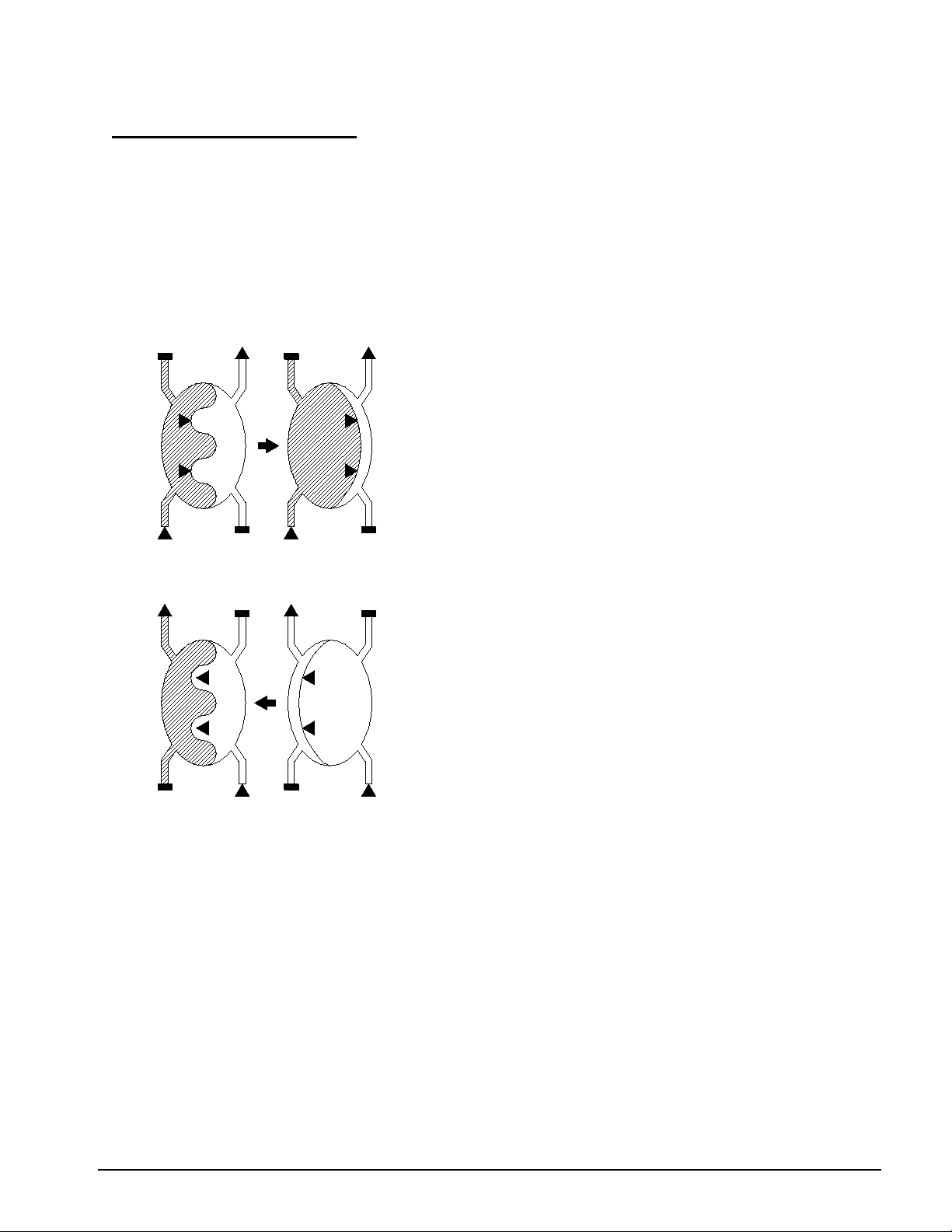
First phase of cycle:
The liquid entering the left hand
compartment expels an equal quantity
on of
After the diaphragm cavity flow
entering the right hand compartment
maximum deflection of the diaphragm,
volume in the chamber.
Va
Vf
Vf
Va
5. Proportional Mixing System
The balance chamber is also part of the mixing system. After each filling of a balance chamber, the
acid pump makes one stroke supplying the correct amount of acid into the hydraulic mixing
chambers. If bicarbonate is employed, the bicarbonate pump will make one or two strokes depending
on the bicarbonate level selected and the type of acid used.
Fig III-1a: Diagram of Dialysate Chamber System
from the right hand compartment via the
diaphragm. At maximum deflecti
the diaphragm, the expelled volume Va is
equal to the volume of the chamber.
In the two described cases the volume expelled from either compartment equals exactly the total
volume of the chamber:
The use of only one chamber would produce an irregular flow. In order to obtain a continuous flow
of dialysate, a further chamber is switched parallel to the first chamber and operated at an inverse
sequence.
Second phase of cycle:
directions have been reversed, the liquid
expels the same quantity from the left
hand compartment via the diaphragm. At
the expelled volume Vf is equal to the
Vf = volume of chamber = Va
Vf = Va
2008T Technician’s Manual – 490130 Rev. H II-10
Page 16
Section II – Hydraulic Description
1
FS
PUMP
DIALYZER
2
FS
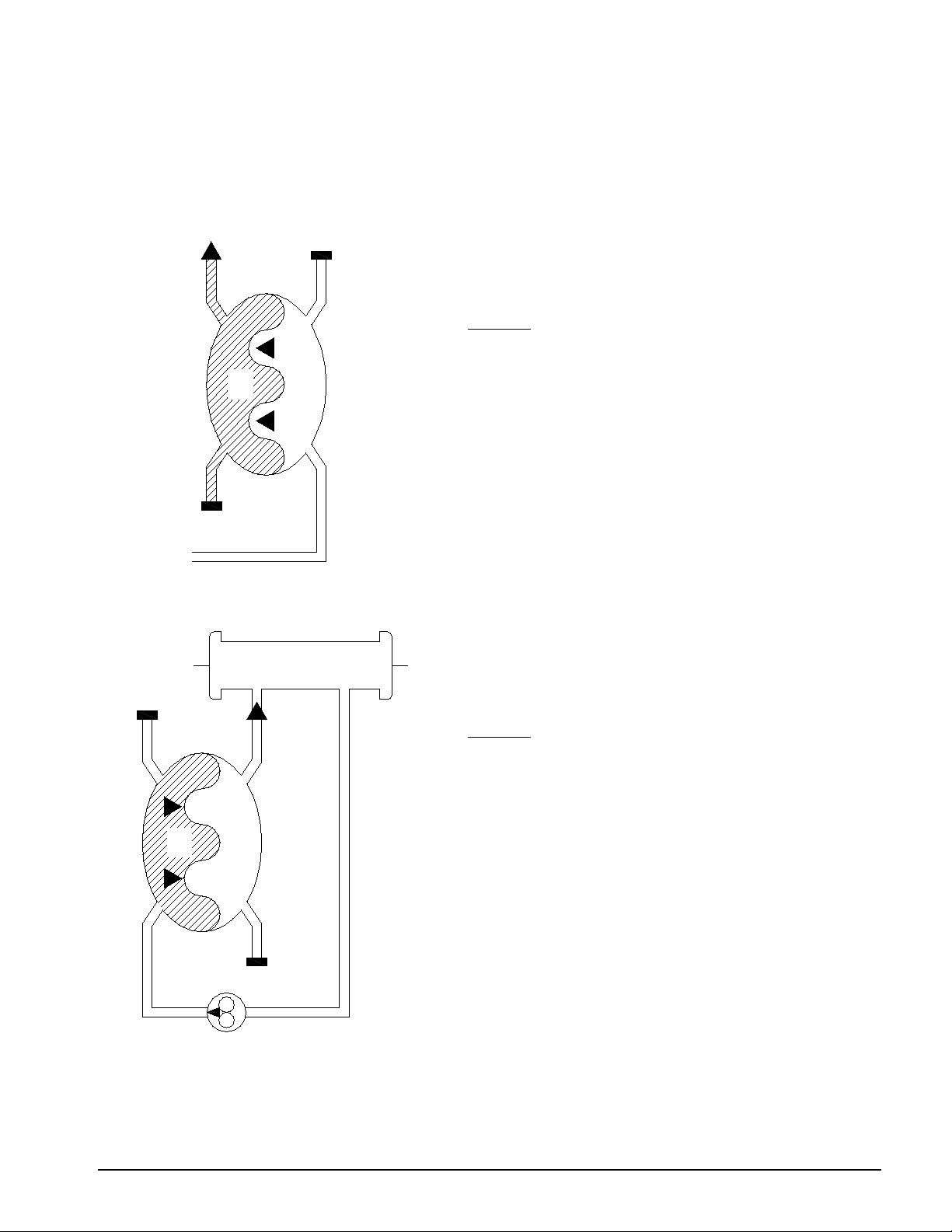
Figure III-1b: Dialysate Balancing Chamber (Phases of One Chamber)
It is insured that the same amount of dialysate is always fed to the dialyzer and discharged by the
dialyzer.
Phase 1:
The right-hand side of the balance chamber fills with
fresh dialysate. The resulting pressure on the
membrane forces the spent dialysate solution out.
Phase 2:
The left hand compartment fills with used dialysate.
With just one balance chamber, dialysate would be unable to flow constantly through the dialyzer, as
the two phases have to succeed one another. Therefore, the system has two balance chambers that
work alternately.
The fresh dialysate is pressed to the dialyzer.
2008T Technician’s Manual – 490130 Rev. H II-11
Page 17

OUTLET
F
1
S
PUMP
DIALYZER
2
FS
OUTLET
F
1
S
PUMP
DIALYZER
2
FS
Figure III-1c: Dialysate Balancing Chamber (Phases of Two Chambers)
Phase 1:
In the left hand balance chamber the used
dialysate is expelled by fresh dialysate. At
the same time, the fresh dialysate in the
right hand chamber is forced to the
dialyzer by used dialysate.
Phase 2:
The two balance chambers have
interchanged their functions.
Section II – Hydraulic Description
2008T Technician’s Manual – 490130 Rev. H II-12
Page 18

Section II – Hydraulic Description
DISTRIBUTION BOARD LAYOUT
Definition of component function
x2. Temperature control thermistor (CON-NTC)
Controls temperature in the heater chamber.
x3. Temperature monitor thermistor (MON-NTC)
Monitors dialysate temperature before the dialyzer. Bypass is initiated when the
temperature is out of limits.
x4. Not Used
x5. Level sensor (float) in the hydrochamber (FLOAT-SW)
Controls water inlet valve 41 and its signal is used to detect flow problems.
x6. Air sensor in air separation chamber (AIR-SEN)
Detects air coming from the dialyzer and is used to trigger the filling program.
x7. Conductivity cell (COND)
Monitors the dialysate conductivity before the dialyzer. Bypass is initiated when
conductivity is out of limits.
x8. Blood leak detector (BLOOD LEAK)
Detects blood in the return line of the dialyzer and triggers the minor blood leak warning
and the blood leak alarm.
x9. Dialysate pressure transducer (P-DIAL)
Measures the dialysate pressure. This value is used to calculate the TMP.
x10. Chamber full switch (CFS)
The pressure spike seen by this transducer is used to switch the balance chamber. The
time between pulses and the selected flow rate will set the voltage to the flow pump. It is
intended to limit the height of the pressure spike to a certain value (a little higher than the
loading pressure at all pump speeds).
x11. Reed switch for acid connector (CONC-SW)
Used to detect presence of acid connector.
x12. Reed switch for bicarbonate connector (BIC-SW)
Used to detect presence of bicarbonate connector.
2008T Technician’s Manual – 490130 Rev. H II-13
Page 19

Section II – Hydraulic Description
Definition of component function (cont.)
x13. Post Conductivity Cell (COND-POS)
Monitors the dialysate conductivity after the dialyzer. Used during Online Clearance
(OLC) testing.
x44. Post Temperature thermister (NTC-POST)
Monitors the temperature in the dialysate after the dialyzer. Used during Online
Clearance (OLC) testing.
x14. Not Used
x15. Dialysate Sampling Valve (Optional)
Valve 15
Used to collect a sample of dialysate
x16. Acid pump with end of stroke sensor (CONC-P)
Delivers acid into the mixing chamber. It will fully discharge its volume and refill on
every switching of the balance chamber.
x17. Bicarbonate pump with end of stroke sensor (BIC-P)
Delivers bicarbonate into the mixing chamber. It will fully discharge its volume and
refill (possibly twice depending on the volume needed for the acid selected) on every
switching of the balance chamber.
x18. Digital Heparin pump
x19. Not Used
x20. Deaeration pump (DEGAS-P)
Is calibrated in software, using a pressure gauge on the inlet of the pump.
The pressure is set to -24 inches of Hg (-610 mmHg).
x21. Flow pump (FLOW-P)
It is controlled by software. The pump speed depends on the flow rate selected.
x22. UF pump (UF-P)
The volume is calibrated to 1ml per stroke. The frequency of strokes is controlled by
software.
x23. Not Used
x24. Dialyzer valve 1 (DIAL-V1)
Valve 24
x25. Dialyzer valve 2 (DIAL-V2)
Valve 25
2008T Technician’s Manual – 490130 Rev. H II-14
Page 20

Definition of component function (cont.)
x26. Bypass valve (BYPAS-V)
Valve 26
x27 Inlet Water Valve (IN-V)
Valve 41
This valve is controlled via level sensor #5.
x28. DIASAFE PLUS test valve
Valve 28
Used during the DIASAFE PLUS test process.
x29. Recirculation valve (REC-V)
Valve 29
x30. Drain valve (DRAIN-V)
Valve 30
x31 Balance chamber valve 31.
x32. Balance chamber valve 32.
x33. Balance chamber valve 33.
x34. Balance chamber valve 34.
x35. Balance chamber valve 35.
x36. Balance chamber valve 36.
x37. Balance chamber valve 37.
x38. Balance chamber valve 38.
x39. Bypass valve for deaeration orifice - valve 39.
This valve is on in all cleaning cycles.
x40 Not Used
x41. Vent valve for air separation - valve 43.
SENSORS Ribbon cable connection from Sensor board.
ACTUATOR Ribbon cable connection from Actuator-Test board.
Section II – Hydraulic Description
2008T Technician’s Manual – 490130 Rev. H II-15
Page 21
Section II – Hydraulic Description
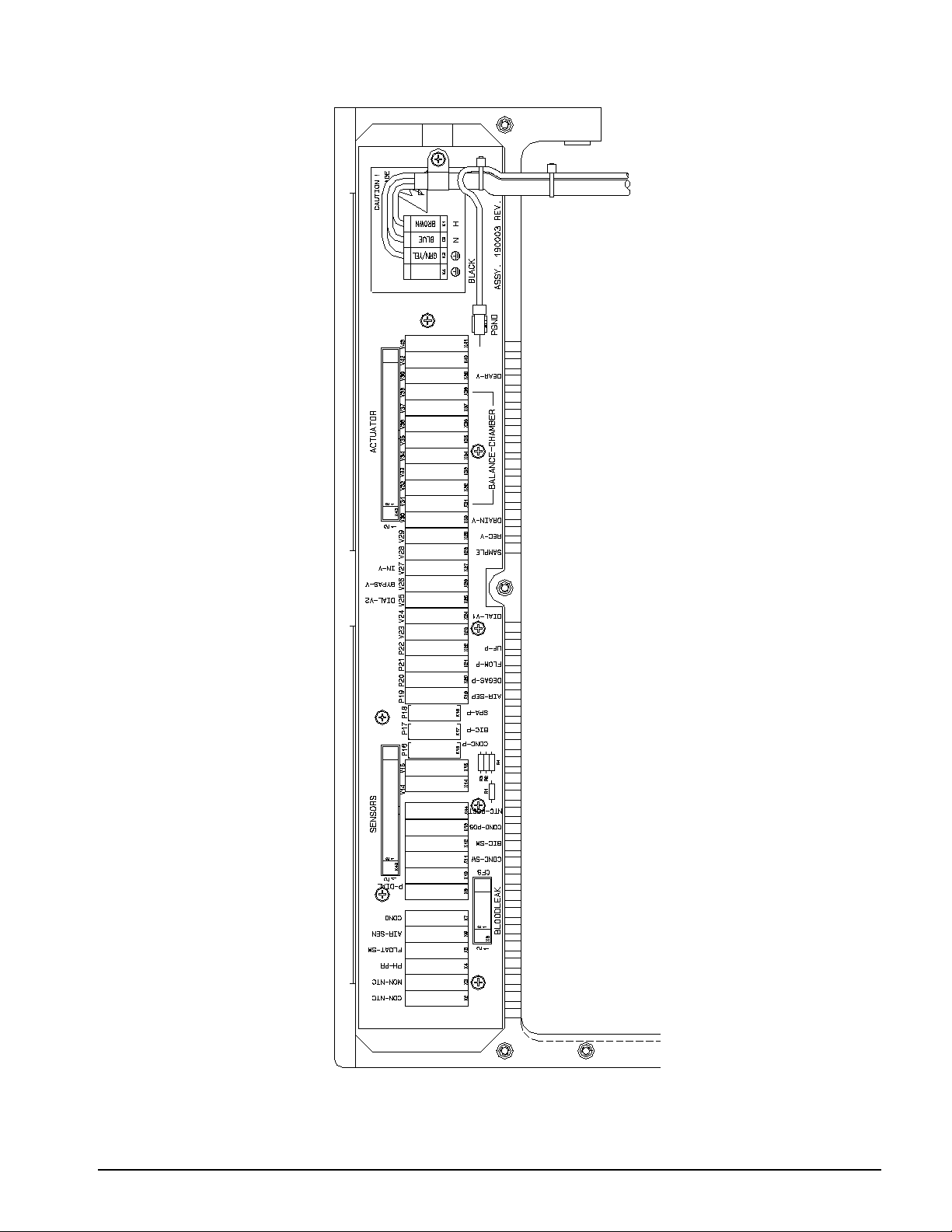
DISTRIBUTION BOX ASSEMBLY
2008T Technician’s Manual – 490130 Rev. H II-16
Page 22

Section III – Electronic Circuit Description
Touch Screen
Front Panel
Integral part of the front panel that handles the
Status Light
Display Panel
Three color omni-directional light display
SECTION III – ELECTRONIC CIRCUIT D E SCRIPTION
BRIEF DESCRIPTION & LOCATION OF ELECTRONICS
COMPONENT LOCATION DESCRIPTION
Power Control board Power Supply Magneto-resonant power supply, 24V, heater
supply, stand-by power supply and heater control
circuit.
user inputs to the color LCD display.
Color LCD Display assembly Display Panel Color LCD display with integral backlight
integrated into the top of the Display Panel.
Keypad assembly Front Panel Interfaces all LEDs and keys on the Control Panel
keypad with the UI-MICS board.
Keyboard assembly Front Panel Device that handles user input to the UI-MICS
board.
Touchpad assembly Front Panel Touch sensitive device used to move the cursor
and select on screen entry points. Also
incorporates CONFIRM and Escape keys.
UI – MICS board Card Cage Interfaces the LCD display, Keypad, Keyboard,
and Touchpad with the Motherboard and
Functional board.
Hosts the CDX PC module (optional).
Motherboard Card Cage Distribution board for card cage boards
Power Logic board
w/12 Volt Inverter built-in
Actuator-Test board Card Cage Actuator: Drivers and control for valves, pumps
Functional board Card Cage Functional processor; operating logic control and
Sensor board Card Cage Amplifiers for pressure transducer, temperature,
Distribution board Hydraulic Interconnection of hydraulic components to the
Card Cage +5v, +12v, DC to DC converters and
-12v for blood pressure module
and monitors board interface for sensor and
secondary monitor (independent A/D converter)
circuits
Test: Monitor for Functional board watchdog, test
signal generator
control of displays
conductivity and other sensors, ADCs
card cage
Blood Leak Detector Hydraulic Potted SMD board, BLD electronics
For troubleshooting purposes, refer to the 2008T Electronic Block Diagrams (P/N 290443) which is
a set of diagrams illustrating the interconnectivity of the card cage, modules, and hydraulics.
2008T Technician’s Manual – 490130 Rev. H III-1
Page 23

Fn
F12
F11
F10F9F8
F7
F6F5
F4
F3
F2F1
KEYPAD
TOUCHPAD
KEYBOARD
- LCD DISPLAY
- TOUCHSCREEN
- BACKLIGHT
- INVERTER BOARD
FOR BACKLIGHT
- USB PORT 1
MACHINE STATUS LIGHT
CARD CAGE
(LEFT TO RIGHT)
POWER LOGIC BOARD
ACTUATOR/TEST BOARD
FUNCTIONAL BOARD
UI - MICS BOARD
SENSOR BOARD
Section III – Electronic Circuit Description
CIRCUIT BOARD LAYOUT
2008T Technician’s Manual – 490130 Rev. H III-2
Page 24

Section III – Electronic Circuit Description
Warning! Do not connect devices requiring an external AC power connection to the
ports may adversely affect the machine's electrical safety and patient isolation.
CDX
Dialysis
Dialysis Alarm
USB Port 2
9 Volt
Serial
Ethernet
REAR PANEL OPERATING ELEMENTS
Volume Control
Interface
Speaker
Connector
Speaker
Battery
CDX SPEAKER – Sound from the CDX PC (optional) will be produced by this speaker. It is muted
when displaying the dialysis screen.
DIALYSIS SPEAKER - The machine can make two kinds of sounds: a warning sound, and an alarm
sound. The two sounds are quite distinct; the first one is used for lower priority alarms, and the
second for more important alarms.
USB PORT 2 – Expansion for CDX PC (optional). Only self powered USB devices may be
connected when the 2008T is used with a patient.
machine's USB ports (for example: printers, card readers, or USB hard drives that
plug into a wall outlet). Only freestanding (self-powered) devices such as USB flash
drives are permitted. Inserting a powered USB device into your machine's USB
SERIAL INTERFACE – Electrically isolated RS 232 serial interface connector; used for transferring
machine data to a medical information system.
ETHERNET CONNECTOR – 10/100 Ethernet connection for the CDX PC (optional); electrically
isolated.
2008T Technician’s Manual – 490130 Rev. H III-3
Page 25

Section III – Electronic Circuit Description
Note: The power supply cord is replaceable by service personnel only. Refer to the 2008
Replacement Kit (P/N 190714) for correct connection and anchoring of the power cord.
REAR PANEL OPERATING ELEMENTS (cont.)
DIALYSIS ALARM VOLUME CONTROL – Used to adjust the volume (sound pressure level) of
the dialysis machine audible warnings and alarms. Warning sound is adjustable between 75 dBA
and 89 dBA (at 1 meter). Alarm sound is adjustable between 67 dBA and 81 dBA (at 1 meter).
Does not affect the volume from the separate CDX speaker.
POWER FAILURE ALARM - 9V heavy duty alkaline battery for main power failure
WIFI ADAPTER (not shown) - Wireless adapter used by the CDX PC (optional). It is mounted
behind the front panel keypad; inside the card cage. It contains an internal antenna.
HYDRAULIC CONNECTION PANEL
TO DIALYZER - tube to dialyzer
FROM DIALYZER - tube from dialyzer
WATER INLET - tube for water inlet
TO DRAIN - outlet tube to drain
GROUND - fixing screw for potential equalization
POWER SUPPLY PANEL
HEATER BREAKER – separate line voltage breaker for heater element
MAIN BREAKER - main line voltage switch
Note: To isolate machine from mains supply, toggle this switch to the O position.
POWER CABLE - cable connection to wall GFCI
Power Cord Replacement Instructions included in 2008 Power Supply Cord
2008T Technician’s Manual – 490130 Rev. H III-4
Page 26

Section III – Electronic Circuit Description
ELECTRONIC BOARD DESCRIPTIONS
FRONT PANEL AND DISPLAY
1. OVERVIEW
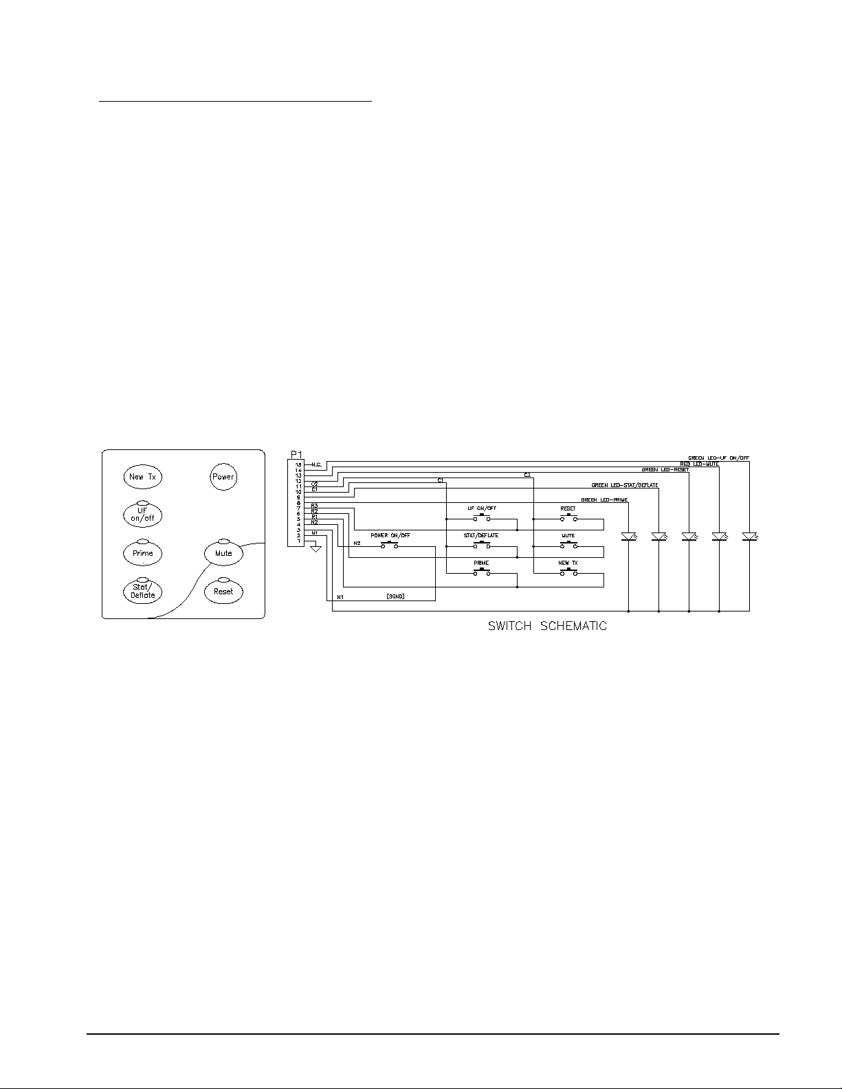
The front panel consists of seven areas, the display screen, the touch screen, the keypad, a full
keyboard, touchpad, a status light and USB port 1. The display screen and touch screen is the
area under the glass in the center of the front panel. The status light is above the display screen.
The keypad is to the right of the display screen and contains membrane keys. Note the
keyboard and touchpad fold down 90 degrees from under the display screen and keypad. All of
these are controlled by the Functional board under software control. USB port 1 is under a flap
to the right of the display screen.
Display Screen
The display screen consists of a 15 inch, native resolution 1024x768 pixel LCD graph ic
display module through which extensive textual and graphical information can be displayed
pertaining to the current operational status, diagnostics functions, or calibrations.
Touch Screen
The touch screen is located in front of the display screen. It allows for user selection by
directly touching the display screen.
Keypad
The keypad is located to the right of the LCD display. It has seven keys to interact with the
user interface. These keys are New Tx, UF on/off, Prime, Stat/deflate, Power, Mute, and
Reset. Four of these keys have green LED’s indicating the state of that keys function.
These keys are the UF on/off, Prime, Stat/deflate, and the Reset. One key has a red LED
and it is the Mute key.
Keyboard
A full 76 key keyboard is located under the display screen. It is able to be folded up and
out the way flush with the display screen. Once folded down, data can be easily input
using a standard QWERTY layout keyboard.
Touchpad
The touchpad is a touch sensitive device used to move the cursor and select on screen entry
points. The touchpad assembly also incorporates a CONFIRM key and an Escape key.
2008T Technician’s Manual – 490130 Rev. H III-5
Page 27

FRONT PANEL AND DISPLAY (cont.)
Warning! Do not connect devices requiring an external AC power connection to the
ports may adversely affect the machine's electrical safety and patient isolation.
Status Light
The machine status light is built into the top of the display screen assembly. It consists of
an array of green, yellow and red colored LEDs which light in regards to the status of the
machine. Refer to the 2008T Operators Manual (P/N 490122) for proper use of this
feature.
USB Port 1
Used for updating Functional, Actuator-Test and UI–MICS software.
Used to transfer settings between two or more 2008T Hemodialysis machines. Refer to the
2008T Options Configurator Instructions (P/N 508635).
machine's USB ports (for example: printers, card readers, or USB hard drives that
plug into a wall outlet). Only freestanding (self-powered) devices such as USB flash
drives are permitted. Inserting a powered USB device into your machine's USB
Section III – Electronic Circuit Description
2. LEDs
The Keypad has 5 LEDs. These are used primarily to indicate machine status. During the light
show, the LEDs are tested, one by one. At other times, they have the following meanings:
1. Mute - Lit if muting is active.
2. Reset – Normally not lit. Lit if alarm is active. Flashing if the message displayed asks
the user if they want new arterial, venous, or TMP limits (blood alarm).
3. Prime - Lit during priming.
4 UF on/off - Flashes if there is a blood alarm or treatment time is paused, lit if UF is
actually on or the user turned it on, off if the user turned it off.
5. Stat/Deflate - Lit when Blood Pressure Cuff is pressurized.
2008T Technician’s Manual – 490130 Rev. H III-6
Page 28
Section III – Electronic Circuit Description
FRONT PANEL AND DISPLAY (cont.)
3. MEMBRANE SWITCHES
The membrane switches embedded in the Keypad overlay are spring-loaded, momentary action,
contact type switches. The membrane switch signals are connected through a flexible cable that
plugs into User Interface board.
The Power ON/OFF membrane switch, when pressed, grounds the PWR-ON signal to the
Power Logic board. The PWR-ON signal is routed through the User Interface board. This
causes the Power ON/OFF circuit on the Power Logic board to change state. The current state
of this circuit will determine whether pressing the Power ON/OFF membrane switch turns the
main power ON or OFF.
The remaining membrane switches are scanned by the UI–MICS board and sent to the
Functional board to determine the action that will be taken in response to the membrane switch
pressed.
There are many keys on the Keypad, Touchpad and Keyboard. All keys are debounced and the
key may be passed on to the section of the program that will process it. The Power on/off key
cannot be read by the Functional board. The Power on/off key is handled by the power logic
board.
The functions of the keys are as follows:
a. Mute
Mute alarm and warning sounds for 2 minutes, if not already muting and an alarm or
warning exists. Outside of dialysis, allow muting of warning sounds. Note that
muting is turned off whenever a new alarm occurs. Note that fatal alarms (which shut
down the machine) cannot be muted.
2008T Technician’s Manual – 490130 Rev. H III-7
Page 29

FRONT PANEL AND DISPLAY (cont.)
b. Reset
Pressing the Reset key clears clearable alarms. Pressing and holding the key for two
seconds will spread the alarm window by 300 mmHg for arterial and venous
pressures and fully open the transmembrane (TMP) pressure window for 30 seconds.
During this time, the light above the Reset key will not be on. During a blood leak
alarm, pressing and holding the key for three seconds will override the alarm and
keep the blood pump running for three minutes. The light above the Reset key will
be on during an override.
Warning! During an override, the machine’s blood leak detector is inactive. You
must monitor the treatment.
Note: The Reset key light flashes when a resettable alarm occurs.
c. Escape
The Escape key can be found in two places; the Touch Pad and the Keyboard. It is
used to cancel a change to a parameter.
d. Number Keys (0-9)
These keys are used to enter parameters.
e. Alphabet Keys (A-Z and a-z)
f. Up
This key is used to edit a variable, to increase its value and scrolls up when selecting
from a menu. Also, can cycle through the debug screens.
g. Down
This key is used to edit a variable, to decrease its value and scrolls down when
selecting from a menu. Also, can cycle through the debug screens.
h. CONFIRM
The CONFIRM key on the Touchpad has the same function as the Enter key on the
keyboard and is used to accept changed parameters on a screen and to accept an
action as defined on various screens
i. Enter
The Enter key on the Keyboard has the same function as the CONFIRM key on the
touchpad and is used to accept changed parameters on a screen and to accept an
action as defined on various screens
Section III – Electronic Circuit Description
2008T Technician’s Manual – 490130 Rev. H III-8
Page 30

FRONT PANEL AND DISPLAY (cont.)
j. New Tx
The New Tx is used to clear all treatment parameters and prepares the machine for
the next patient.
k. Prime
This key can be used to start priming at any time (except no program state) providing
that blood is not sensed and there is an air detector alarm. If one of those conditions
is false, an appropriate message is displayed; otherwise, priming begins. If priming is
already active, this key turns it off.
l. UF On/Off
If the user has turned UF on (though it may be interrupted by an alarm) this key turns
it off. If UF is off, and the machine is in dialysis, and there are no blood alarms and
no UF Pump Alarm, and there is no Maximum UF Rate Warning, and the UF rate
selected is at least 10 ml/hour, then pressing this key will turn UF on.
m. Stat/Deflate
Press the Stat/Deflate to Start or Stop a Blood Pressure reading.
n. Debug Screen Key
This “key” is a combination of keys strokes to bring up the debug screens. To display
the debug screens, press and hold the CTRL key and then press the up and down
arrow keys at the same time on the keyboard. Use the up and down arrow keys
individually to change between debug screens.
o. CDX Key
This blue key is used enter and exit the optional Clinical Data Exchange (CDX)
system.
p. Fn Lock (Function Lock)
This blue key is used to select the secondary function of the keys with blue function
numbers (F1-F12) at the top of the keyboard. Pressing this key and then pressing a
function key selects that function. The Fn Lock light on the keyboard indicates the
lock status: when the light is on, the function lock is on. Press the FN Lock again to
turn off the function lock.
Section III – Electronic Circuit Description
2008T Technician’s Manual – 490130 Rev. H III-9
Page 31

Section III – Electronic Circuit Description
TOUCHPAD
RESET
BOARD
POWER LOGIC
BOARD
WIFI
ADAPTER
USB PORT 1
TOUCHSCREEN
DIALYSIS
SPEAKER
ETHERNET
CONNECTOR
USB PORT 2
CDX
SPEAKER
FUNCTIONAL
BOARD
UI - MICS
BOARD
DISPLAY
ASSEMBLY
MACHINE
STATUS
LIGHT
BACKLIGHT
INVERTER BOARD
LCD
DISPLAY
KEYBOARD
KEYPAD
TOUCHPAD
SCREEN DATA
New Tx
UF on/off
Prime
Stat/deflate
Power
Mute
Reset
Confirm
Escape
MOTHER
BOARD
CARD CAGE
UI - MICS BOARD
The UI - MICS board interfaces the display screen, keyboard, keypad and touchpad with the
motherboard. This board transfers screen data from the Functional board and upscales it to the
15 inch LCD display.
The UI - MICS board hosts the CDX PC (optional) and all of its peripheral components. These
components include an Ethernet connection and a USB port. These components are available on the
rear of the card cage. The CDX PC has a dedicated speaker separate from the Dialysis speaker. A
Wifi adapter is mounted inside the card cage behind the keypad.
2008T Technician’s Manual – 490130 Rev. H III-10
Page 32

Section III – Electronic Circuit Description
UI - MICS Board
Connector Usage
Note: The Touchpad Reset board is incorporated on newer UI-MICS boards. A
separate Touchpad Reset board is not required.
2008T Technician’s Manual – 490130 Rev. H III-11
Page 33

Section III – Electronic Circuit Description
ACTUATOR-TEST BOARD
The Actuator-Test board combines the functionality of an Actuator and Test boards. For the purpose
of clarity, they can be described separately.
ACTUATOR BOARD FUNCTIONALITY
1. OVERVIEW
The main functions of the actuator board are to control the hydraulic system of the dialysis
machine, communicate with the Functional board and also monitors the system to determine if
the machine is working properly. Also provides redundancy to Sensor board for hard limits
(alarm) checking. If not, it will send alarm(s) to the Functional board through the
communication and take corresponding action to the hydraulic system to make sure that the
machine is absolutely safe.
2. PROGRAM FLOW
When the machine is turned on, it first goes through an initialization sequence. Then it goes
into an endless loop. All program activities happen in this loop as background tasks while
waiting for the interrupt. Within this loop it first reads in all necessary hardware data such as:
flow switch on/off, dial lines in/out, shunt door open/close, acid and bicarbonate wands in/out,
bicarbonate and acid pump end of stroke signal, state of the dip switches, blood sensed signal,
etc. There is a 10 ms timer interrupt that controls the machine steps. If the 10 ms is not up, the
program will update every valve, process the communication data coming from the Functional
board and update the data, which will be sent to the Functional board.
When the 10 ms timer interrupt occurs, it first resets the interrupt flag for the next interrupt,
updates the balance chamber switch counter and the run time counter which remembers how
long the machine runs, reads some ADC channels, and then if the machine is just started and the
deaeration pump steps have been received from the Functional board, does the preparation for
the hydraulic system (only once when the machine starts up).
After the preparation is done, the machine is in the no program state, which means the machine
sets up the main menu waiting for a command from the Functional board. Depending upon the
command, the machine executes the dialysis program or one of the rinse/disinfect program or
calibration program. Also the actuator board does redundant monitoring within this 10ms. The
redundant monitoring checks bicarbonate and acid pumps, checks the flow, the UF pump, the
temperature and conductivity limits, the arterial, venous, and TMP pressure limits, monitors
water alarms, monitors blood alarms, and shuts off the machine if a water alarm or blood alarm
or actuator board EPROM CRC error occurs for a certain period of time. Also, the heater will
be controlled based on different alarm conditions.
2008T Technician’s Manual – 490130 Rev. H III-12
Page 34

Section III – Electronic Circuit Description
Note: All references to “Actuator board” actually refer to the Actuator-Test board.
3. ALARMS
There are many alarms generated by the actuator board. These alarms are displayed by the
Functional board.
4. ADC CHANNELS
There are 8 A to D channels:
(1). Channel 0: Read in Chamber Full Switch.
(2). Channel 1: Read in dialysate pressure.
(3). Channel 2: Read in arterial pressure.
(4). Channel 3: Read in venous pressure.
(5). Channel 4: Read in temperature.
(6). Channel 5: Read in blood leak voltage.
(7). Channel 6: Read in 1.2V reference.
(8). Channel 7: Read in 24V.
2008T Technician’s Manual – 490130 Rev. H III-13
Page 35

Section III – Electronic Circuit Description
TEST BOARD FUNCTIONALITY
The Test & Options Screen allows the user to perform tests to troubleshoot the machine. These
tests include an Alarm Test, a Pressure Test, Both Alarm and Pressure Tests, and a DIASAFE
PLUS Filter Test.
Both Tests Button:
The Both Tests button performs the Alarm Test and the Pressure Test. These tests include the
following tests:
• Air Detector
• Blood Leak
• Arterial Pressure
• Venous Pressure
• TMP Pressure
• Battery
• Optical Detector
• Temperature
• Conductivity
• Negative Pressure
• Positive Pressure
Once Both Tests is started there will be banners displayed indicating what process is being
performed.
Both Tests will only start if the machine is alarm free, the TX Clock is not running, the
dialysate lines are in the shunt box, and blood is not sensed. All tests are performed at a
500ml/min flow rate.
Note: All references to “Test board” actually refer to the Actuator-Test board.
The following table shows the sequence in which each banner is displayed during the
performance of Both Tests and what process is being performed:
Both Tests
Banner Sequence
Test: (Get Neg TMP) Air is remove d from the system by creating an air fill program
Test: Air Detector The Test board sets LDSA signal to 5V. This causes the level
Test: Blood Leak The Test board detunes the blood leak detector. The blood
Process Being Performed
if needed then a negative pressure (-100) is achieved
detector to reduce the ultrasonic signal across the level
detector by 1/3. The level detector reacts by closing the
clamp and sending an alarm condition to the Functional
board. The Functional board shuts off the blood systems and
turns the level detector alarm led on. The Test board monitors
the clamp close and the blood pump off.
leak detector reacts by reducing the output signal below the
normal alarm threshold. Functional board reacts by closing
the clamp and shutting off the blood pump. Functional board
monitors the blood pump stopped.
2008T Technician’s Manual – 490130 Rev. H III-14
Page 36

Section III – Electronic Circuit Description
5V.
Both Tests
Banner Sequence (cont.)
Test: Art High Hard The Test board sets the det uning DAC to 0V and then turns
Test: Art Low Hard The Test board sets the det uning DAC to 10V and then turns
Process Being Performed
on the CMOS switch. The zero adjustment for the arterial
pressure transducer is pulled low. Using the equation o f the
circuit Vout = f(gain)*Vgain -f(offset) *Vo ffset + 5V, a low to
the offset adjustment causes a Vout considerably above 5V.
The Functional board along with the ADC on the Sensor
board measures this detuned arterial pressure of over
350 mmHg. The Functional board reacts to the upper hard
limit alarm by turning off the blood pump. The Test board
senses the blood pump off. The Test board turns t he CMOS
switch off.
on the CMOS switch. The 0 adjustment for the arterial
pressure tr ansducer is pulled high. Using the equation o f t he
circuit Vout = f(gain)*Vgain -f(offset)*Voffset + 5V, a high
to the offset adjustment causes a Vout considerably below
The Functional board along with the ADC on the Sensor
board measures this detuned arterial pressure of under
-300 mmHg. The Functional board reacts to the lower hard
limit alarm by turning off the blood pump. The Test board
senses the blood pump off. The Test board turns the CMOS
switch off.
Test: Art High Soft The Test board sets the detuning DAC to a value between 1V
and 4V. The TP then turns on the CMOS switch. The 0
adjustment for the arterial pressure transducer is pulled low.
Using the equation of the circuit Vout = f(gain)*Vgain f(offset)*Voffset + 5V, a low to the offset adjustment causes a
Vout above 5V. The Functional board along with the ADC
on the Sensor board measures this detuned arterial pressure of
around 200 mmHg. After 5 seconds, the Functional board
reacts to the upper auto-limit alar m by turning off the blood
pump. The Test board senses the blood pump off. Alarms are
cleared; the auto-limits are set around this new actual arterial
pressure.
Test: Art Low Soft The Test board turns off the CMOS switch. Arterial pressure
returns to 0 mmHg. After 5 seconds, t he Functiona l board
reacts to the lower auto-limi t alarm by turning off the blood
pump. The Test board senses the blood pump off. The Test
board turns the CMOS switch off.
Test: Ven High Hard
Test: Ven Low Hard Same as the Art Low Hard test but with the venous pressure
Test: Ven High Soft Same as the Art High Soft test but wit h the venous pressure
Same as the Art High Hard test but with the venous pressure
transducer on the level detector.
transducer on the level detector.
transducer on the level detector.
Test: Ven Low Soft Same as the Art Low Soft test but wit h the venous pressure
transducer on the level detector.
2008T Technician’s Manual – 490130 Rev. H III-15
Page 37

Section III – Electronic Circuit Description
Both Tests
Banner Sequence (cont.)
Test: TMP High Hard Same as the Art High Hard test but with the dialysate pressure
Process Being Performed
transducer.
Test: TMP Low Hard
Test: TMP High Soft Same as the Art High Soft test but with the dialysate pressure
Test: TMP Low Soft Same as the Art Low Soft test but with the dialysate pressure
Test: 9 Volt Battery The Test board sets T-BATT signal to 5V. This causes a load
Test: Optical Detector The Test board detunes the optical detector and a venous
Test: Temp High Hard The Test board detunes the actual temperature value so that it
Test: Temp Low Hard The Test board detunes the actual temperature value so that it
Test: Temp High Soft The Test board detunes the actual temperature value so that it
Same as the Art Low Hard test but with the dialysate pressure
transducer.
transducer.
transducer.
to be connected across the battery. The battery is now
checked for a voltage greater then 7V. If the alkaline battery
voltage is above 7V the test passes. The T-BATT signal is
removed.
pressure alarm must occur for the test to pass.
is above the high hard limit to test that the machine goes into
bypass and the heater relay turns off.
is below the low hard limit to test that the machine goes into
bypass.
is above the high soft limit to test that the machine goes into
bypass.
Test: Temp Low Soft The Test board detunes the actual temperature value so that it
is above the low soft limit to test that the machine goes into
bypass.
Test: Cond High Soft
Test: Cond Low Soft The Test board detunes the actual conductivity value so that it
Test: (Remove Air) Air is removed from the system by creating an air fill pr ogram
Test: (Get Neg TMP) Positive pressure is achieved, and then a dialysate pressure of
Test: Neg Flow On
The Test board detunes the actual conductivity value so t hat it
is above the high soft limit to test that the machine goes into
bypass.
is above the low soft limit to test that the machine goes into
bypass.
if needed
at least -270 is reached
There is a 30 second delay for the pressure to stabilize (the
test fails i f during this time the pressure is out of the range of
-250 to -450), and then a 30 second test, during which the
dialysate pressure must not vary more than a 21mmHg
2008T Technician’s Manual – 490130 Rev. H III-16
Page 38

Section III – Electronic Circuit Description
Both Tests
Banner Sequence (cont.)
Test: (Get Pos TMP) A dialysate pressure of at least +350 is achieved (to check the
Process Being Performed
upper most end of the scale)
Test: POS Flow Off
Test: (Get Neg TMP) Positive pressure is achieved, and then a TMP of at least -100
There is a 20 second delay for the pressure to stabilize (the
test fails i f during this time the pressure is out of the range
+180 to +350), and then a 30 second test, during which the
TMP must not vary more than 30 mmHg. 30 seconds for both
on Diasafe equipped machines.
is reached
Pressure Test Button:
The Pressure Test button performs the following tests:
• Negative Pressure
• Positive Pressure
Once the Pressure Test is started there will be banners displayed indicating what process is
being performed.
The Pressure Test will only start if the machine is alarm free, the TX Clock is not running, the
dialysate lines are in the shunt box, and blood is not sensed. All tests are performed at a
500ml/min flow rate.
The following table shows the sequence in which each banner is displayed during the Pressure
Test and what process is being performed:
Pressure Test
Banner Sequence
Process Being Performed
Test: (Remove Air) Air is removed from the system by creating an air fill program
if needed
Test: (Get Neg TMP) Positive pressure is achieved, and then a dialysate pressure of
at least -270 is reached
Test: Neg Flow On There is a 30 second delay for the pressure to stabilize (the
test fails i f during this time the pressure is out of the range of
-250 to -450), and then a 30 second test, during which the
dialysate pressure must not vary more than a 21mmHg
Test: (Get Pos TMP)
Test: POS Flow Off There is a 20 second delay for the pressure to stabilize (the
Test: (Get Neg TMP)
A dialysate pressure of at least +350 is achieved (to check the
upper most end of the scale)
test fails if during this time the pressure is out of the range
+180 to +350), and then a 30 second test, during which the
TMP must not vary more than 30mmHg. 30 seconds for both
on Diasafe equipped machines.
Positive pressure is achieved, and then a TMP of at least -100
is reached
2008T Technician’s Manual – 490130 Rev. H III-17
Page 39

Section III – Electronic Circuit Description
Alarm Test Button:
The Alarm Test button performs the following tests:
• Air Detector
• Blood Leak
• Arterial Pressure
• Venous Pressure
• TMP
• Battery
• Optical Detector
• Temperature
• Conductivity
Once the Alarm Test is started there will be banners displayed indicating what process is
being performed.
The Alarm Test will only start if the machine is alarm free, the TX Clock is not running, the
dialysate lines are in the shunt box, and blood is not sensed. All tests are performed at a
500ml/min flow rate.
The following table shows the sequence in which each banner is displayed during the Alarm
Test and what process is being performed:
Alarm Test
Banner Sequence
Process Being Performed
Test: (Get Neg TMP) Air is removed from the system by creating an air fill pro gram
if needed then a negative pressure (-100) is achieved
Test: Air Detector The Test board sets LDSA signal to 5V. This causes the level
detector to reduce the ultrasonic signal across the level
detector by 1/3. The level detector reacts by closing the
clamp and sending an alarm condition to the Functional
board. The Functional board shuts off the blood systems and
turns the level detector alarm led on. The Test board monitors
the clamp close and the blood pump off.
Test: Blood Leak The Test board detunes the blood leak detector. The blood
leak detector reacts by reducing the output signal below the
normal alarm threshold. Functional board reacts by closing
the clamp and shutting off the blood pump. Functional board
monitors the blood pump stopped.
2008T Technician’s Manual – 490130 Rev. H III-18
Page 40

Section III – Electronic Circuit Description
below 5V.
Alarm Test
Banner Sequence (cont.)
Test: Art High Hard The Test board sets the det uning DAC to 0V and then turns
Test: Art Low Hard The Test board sets the det uning DAC to 10V and then turns
Process Being Performed
on the CMOS switch. The zero adjustment for the arterial
pressure transducer is pulled lo w. Using the equation of the
circuit Vout = f(gain)*Vgain -f(offset) *Vo ffset + 5V, a low to
the offset adjustment causes a Vout considerably above 5V.
The Functional board along with the ADC on the Sensor
board measures this detuned arterial pressure of over
350mmHg. The Functional board reacts to the upper hard
limit alarm by turning off the blood pump. The Test board
senses the blood pump off. The Test board turns t he CMOS
switch off.
on the CMOS switch. The 0 adjustment for the arterial
pressure tr ansducer is pulled high. Using the equation o f t he
circuit Vout = f(gain)*Vgain -f(offset)*Voffset + 5V, a high
to the offset adjustment causes a Vout considerably
The Functional board along with the ADC on the Sensor
board measures this detuned arterial pressure of under
-300mmHg. The Functional board reacts to the lower hard
limit alarm by turning off the blood pump. The Test board
senses the blood pump off. The Test board turns the CMOS
switch off.
Test: Art High Soft The Test board sets the detuning DAC to a value between 1V
and 4V. The TP then turns on the CMOS switch. The 0
adjustment for the arterial pressure transducer is pulled low.
Using the equation of the circuit Vout = f(gain)*Vgain f(offset)*Voffset + 5V, a low to the offset adjustment causes a
Vout above 5V. The Functional board along with the ADC
on the Sensor board measures this detuned arterial pressure of
around 200mmhg. After 5 seconds, the Functional board
reacts to the upper auto-limit alar m by turning off the blood
pump. The Test board senses the blood pump off. Alarms are
cleared, the auto-limits are set around this new actual arterial
pressure.
Test: Art Low Soft The Test board turns off the CMOS switch. Arterial pressure
returns to 0 mmHg. After 5 seconds, t he Functiona l board
reacts to the lower auto-limi t alarm by turning off the blood
pump. The Test board senses the blood pump off. The Test
board turns the CMOS switch off.
Test: Ven High Hard
Test: Ven Low Hard Same as the Art Low Hard test but with the venous pressure
Test: Ven High Soft Same as the Art H igh Soft te s t but with the venous pressure
Same as the Art High Hard test but with the venous pressure
transducer on the level detector.
transducer on the level detector.
transducer on the level detector.
Test: Ven Low Soft Same as the Art Low Soft test but wit h the venous pressure
transducer on the level detector.
2008T Technician’s Manual – 490130 Rev. H III-19
Page 41

Section III – Electronic Circuit Description
Alarm Test
Banner Sequence (cont.)
Test: TMP High Hard Same as the Art High Hard test but with the dialysate pressure
Process Being Performed
transducer.
Test: TMP Low Hard
Test: TMP High Soft Same as the Art High Soft test but with the dialysate pressure
Test: TMP Low Soft Same as the Art Low Soft test but with the dialysate pressure
Test: 9 Volt Battery The Test board sets T-BATT signal to 5V. This causes a load
Test: Optical Detector The Test board detunes the optical detector and a blood
Test: Temp High Hard The Test board detunes the actual temperature value so that it
Test: Temp Low Hard The Test board detunes the actual temperature value so that it
Test: Temp High Soft The Test board detunes the actual temperature value so that it
Same as the Art Low Hard test but with the dialysate pressure
transducer.
transducer.
transducer.
to be connected across the battery. The battery is now
checked for a voltage greater then 7V. If the alkaline battery
voltage is above 7V the test passes. The T-BATT signal is
removed.
sensed indication must be received for the test to pass.
is above the high hard limit to test that the machine goes into
bypass and the heater relay turns off.
is below the low hard limit to test that the machine goes into
bypass.
is above the high soft limit to test that the machine goes into
bypass.
Test: Temp Low Soft The Test board detunes the actual temperature value so that it
is above the low soft limit to test that the machine goes into
bypass.
Test: Cond High Soft
Test: Cond Low Soft The Test board detunes the actual conductivity value so that it
The Test board detunes the actual conductivi t y val ue so that it
is above the high soft limit to test that the machine goes into
bypass.
is above the low soft limit to test that the machine goes into
bypass.
2008T Technician’s Manual – 490130 Rev. H III-20
Page 42

Section III – Electronic Circuit Description
Note: The Diasafe Test button is only visible on the Test & Options screen if the
Service Mode.
Diasafe Test Button:
Diasafe and the Diasafe Auto-Test options are set to Yes in Hardware Options of
The Diasafe Test will not start if the dialysate lines are not in the shunt box or if blood is
sensed.
When the Diasafe Test starts the dialysate flow is turned off and the UF Removed is zeroed.
Valves V24 and V25 are turned on and V26 is turned off. The Diasafe Test valve V28 is
turned on. The UF Rate is set to 4000ml/min and allowed to stroke for 100 strokes. The
dialysate pressure is noted and the UF Rate is changed to 2000ml/min. If the dialysate
pressure rises by 60mmHg from the noted reading and reaches above 300 mmHg, the Diasafe
Test passes and displays the “Diasafe Test Passed” banner.
If the dialysate pressure doesn’t rise by 60 mmHg and by the time the UF pump reaches 160
strokes, then the Diasafe Test fails and displays the “Diasafe Test Failed” banner.
2008T Technician’s Manual – 490130 Rev. H III-21
Page 43

P23 - LCD Display Data
P6 - FDS08 or ICare
P7 - CMS208K
P41 - USB Port 1
P10 - Arterial Blood Pump
Serial Communication
P4 - Machine Status
Light (Beacon)
P9 - Transterm, BVM, or
Concentrate Transfer
P8 - BTM or Single Needle Blood
Pump Serial Communication
FUNCTIONAL BOARD
Section III – Electronic Circuit Description
2008T Functional Board Connector Usage
All Other Connectors Not Used
2008T Technician’s Manual – 490130 Rev. H III-22
Page 44

Channel
Volts
Name
Use
1
12.0
BLOOD-DIMNESS
Blood dimness
2
12.0
ART-PRESSURE
Arterial pressure
3
12.0
VEN-PRESSURE
Venous pressure
4
12.0
DIAL-PRESSURE
Dialysate pressure
5
12.0
TEMPERATURE
Temperature
6
11.5
ART-DELIVERY
Arterial blood pump delivery rate
7
11.5
VEN-DELIVERY
Venous blood pump delivery rate
8
6.0
5-VOLTS
5 volts
9
30.0
24-VOLTS
24 volts
10
12.0
ART-KNOB
Arterial blood pump user setting
11
12.0
VEN-KNOB
Venous blood pump user setting
12
30.0
UNUSED
Unused
13
12.0
INLET
Inlet pressure (CFS)
14
0.0
UNUSED
Unused
15
12.0
DISIN-TEMP
Temperature during heat disinfect
SENSOR BOARD
A-to-D CHANNELS
There are 16 a-to-d channels, numbered 0 to 15:
0 12.0 BLOOD-LEAK Blood leak detector
Section III – Electronic Circuit Description
Each of these values ranges from 0 to 255, with 255 representing the maximum voltage. Note
that calibration further affects some values before they are displayed (except in diagnostics).
Conductivity is not an a-to-d channel, but is similar to one as far as the software is concerned.
It is a 16-bit value which describes a frequency associated with the measured conductivity
value.
2008T Technician’s Manual – 490130 Rev. H III-23
Page 45

Section IV – Module Description
SECTION IV – MODULE DESCRIPTION
ARTERIAL BLOOD PUMP MODULE
The blood pump draws blood from the patient and pumps it to the dialyzer and back to the patient in
a closed circuit. As the pump rotor rotates, twin rollers squeeze the pump segment, pulling and
pushing the blood through the blood pump segment. The spring force of the twin rollers is designed
in such a way, that the delivery pressure with the prescribed blood line system is limited, which rules
out ruptures of the blood lines from kinking or clogging. In the cold state, i.e., in the preparation
phase, the delivery pressure is even less and because of the bloodline tolerances; the pump may not
self prime with air. The blood pump segment is held in place by a spring-loaded device located
below the pump rotor. The pump rotor is removable for cleaning.
For reasons of personnel safety, the blood pump will run only when the door is closed. The speed of
the pump can be adjusted using the arrow keys on the blood pump. The blood pump can be stopped
by pressing the Start/Stop key or by opening the blood pump door. When the door is open, the
diameter of the pump segment is shown in the display window.
The arterial pressure monitor port is located above the pump housing. Utilizing the arterial pressure
port and a small air pump the arterial chamber level can be raised. By pressing the Level Adjust
key, the air pump runs and removes air from the arterial chamber allowing the level to rise. Due to
the risk of introducing air into the closed blood circuit, the air pump only removes air to raise the
chamber level and cannot be used to lower it.
If it should become necessary, because of power failure or a line problem, the pump can be operated
manually (in clockwise direction) with a separate hand crank attached to the rear panel of the
machine.
The module is attached to the machine cabinet with two screws. The electrical connection to the
card cage can be removed once the rear panel has been removed.
2008T Technician’s Manual – 490130 Rev. H IV-1
Page 46

Blood Pump Operating and Indicating Elements
Item 1: Delivery rate selectors (up and down keys).
Using the delivery rate selectors, the
delivery rate of the pump can be set to
between 6 ml/min and 600 ml/min
depending on pump segment ID.
Item 2: Blood pump segment tubing diameter selection.
The display of the segment diameter can be
adjusted from 2.6, 4.8, 6.4 and 8.0mm (optional
setting is 2 to 10 mm in 0.2 mm increments*).
The segment diameter is displayed when the door
is opened.
Item 3: Delivery rate display
3 digit LED display Resolution: 5 ml (with 8.0mm blood pump segment)
Red stoppage alarm display lights up if the
rotor stops for 15 seconds (optional 30
seconds*) when blood pump is switched on.
Section IV – Module Description
Item 4: Alarm and Error codes
A set of alarm codes (A.xx) and error codes
(E.xx) will be displayed to inform the operator
of a problem with the blood pump. A
complete list of these codes along with cause
and solution can be found on the next page.
Item 5: Blood pump door.
Switches the blood pump off when opened.
Item 6: Start/Stop key.
Starts and Stops the rotor when pressed.
Item 7: Arterial Pressure port “P ART”
Luer lock.
Item 8: Level Adjust key.
Raises the arterial chamber when pressed.
* Refer to the “Arterial Pressure Calibration” section of the 2008T Calibration Procedures
(P/N 508032) for additional information regarding the blood pump dip-switch settings.
Note: Refer to the “Machine Specifications” section of the 2008T Operator’s
Manual (P/N 490122) for the blood pump specifications.
2008T Technician’s Manual – 490130 Rev. H IV-2
Page 47

Section IV – Module Description
Blood Pump Alarm & Error Codes
ALARM CODES
Below you will find the descriptions of Alarm Codes. Alarm Codes can be cleared by pressing the
Reset keypad. If the Alarm Code returns, use the table below to resolve the alarm condition.
Alarm Code Cause Solution
A.11
A.13
A.16
A.20
A.21
Pump is not reaching speed. Check or replace in the following order:
• Rotor Hall Sensor
• LP955
• LP956
Pump rotor is turning in the wrong
direction.
Key stuck or held in too long. Check or replace in the following order:
Set speed-read back analog
voltage at X348/14 is out of limits
(set speed).
Actual speed-read back analog
voltage at X348/10 is out of limits
(actual speed).
Check or replace in the following order:
• Rotor Hall Sensor
• LP955
• LP956
• User holding key too long
• BP Keypad
• LP955
• LP956
Check or replace LP955.
Check or replace LP955.
A.22
A.24
A.25
Arterial pressure-read back analog
voltage at X348 /7 is ou t o f limits.
Optical sensor frequency (tach)
not in range.
Pressure increases too quickly
when the Level Up key is pressed.
Check or replace LP955.
Check or replace in the following order:
• Motor/Tachometer Assy.
• LP955
• LP956
Check or replace in the following order:
• Vent Valve
• LP955
2008T Technician’s Manual – 490130 Rev. H IV-3
Page 48

Alarm Code (cont.) Cause Solution
Section IV – Module Description
A.26
A.27
A.28
A.29
Pressure was adjusted too much in
calibration mode.
Timeout when receiving IntelHex-line or overflowed receive
buffer.
Error in received Intel-Hex-line.
Pump rotor turning when it should
not be (first revolution).
Check or replace in the following order:
• Pre/Post Pump set wrong
• LP955
Check or replace LP955.
Check or replace LP955.
Check or replace in the following order:
• Rotor Hall Sensor
• LP955
ERROR CODES
Below you will find the descriptions of Error Codes. Error Codes can only be cleared by powering
the machine off. Use the table below to resolve the error condition.
Error Code Cause Solution
E.01
EPROM CRC error.
Check or replace LP955.
E.02
E.03
E.04
E.05
E.06
E.07
E.08
E.09
Flash ROM CRC error.
RAM check error.
Reference Voltage error.
Serial EEPROM error.
Watchdog timeout.
+ 12 volts is outside the allowable
range of 10.8 to 13.2 volts.
+ 24 volts is outside the allowable
range of 22.8 to 28.0 volts.
- 12 volts is outside the allowable
range of -9.6 to -13.2 volts.
Check or replace LP955.
Check or replace LP955.
Check or replace LP955.
Check or replace LP955.
Check or replace LP955.
Check or replace in the following order:
• Machine voltage (+12V)
• 20 pin ribbon cable from machine
• LP955
Check or replace in the following order:
• Machine voltage (+24V)
• 20 pin ribbon cable from machine
• LP955
Check or replace LP955.
2008T Technician’s Manual – 490130 Rev. H IV-4
Page 49

Note: Additional blood pump dip-switch settings can be found in the “Arterial
(P/N 508032).
Error Code (cont.) Cause Solution
Section IV – Module Description
E.10
E.14
E.15
E.23
E.97
E.98
E.99
+ 5 volts is outside the allowable
range of 4.75 to 5.25 volts.
50 ms time period exceeded.
Software task was not completed
correctly.
Pump rotor turning when it should
not be (second revolution).
Error copying data into Flash
ROM.
Error erasing Flash ROM.
Transmit error during Flash
update.
Check or replace LP955.
Check or replace LP955.
Check or replace LP955.
Check or replace in the following order:
• Rotor Hall Sensor
• LP955
Check or replace LP955.
Check or replace LP955.
Check or replace LP955.
RED LED
The large red LED is next to the blood pump display. It will light if the door is open longer than the
preset time of 15 or 30 seconds. This is set using dip-switch 4 on the LP955 board. The default
setting is 30 seconds.
LED Cause Solution
RED LED LIT
Pump door is open longer than 30
seconds.
Check or replace in the following order:
• Door Hall Sensor
• LP955
• LP956
Pressure Calibration” section of the 2008T Calibration Procedures booklet
2008T Technician’s Manual – 490130 Rev. H IV-5
Page 50
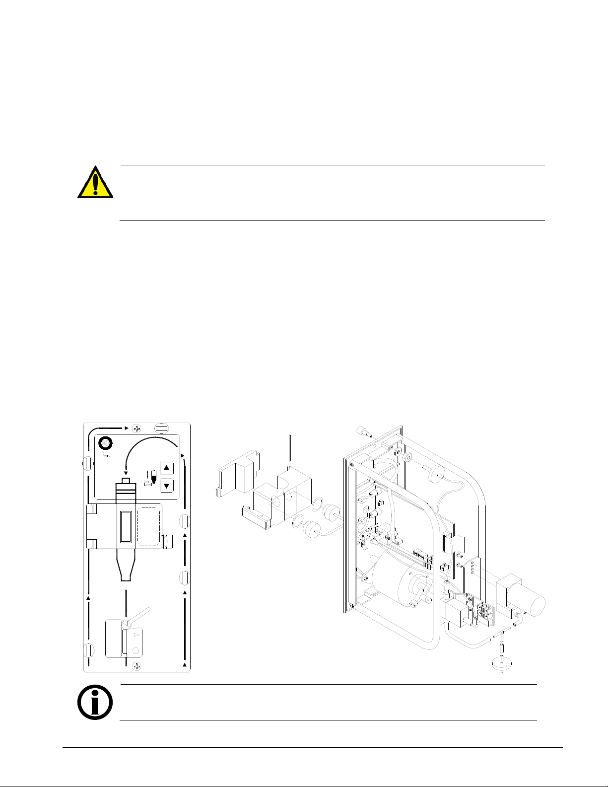
Section IV – Module Description
Warning! The venous drip chamber has to be calibrated for each drip chamber make
the 2008T Calibration Procedures (P/N 508032) for the calibration process.
LEVEL DETECTOR / VENOUS CLAMP MODULE
The module contains the holder for the venous drip chamber with air sensor, the connection for the
venous return pressure and the venous clamp with optical blood/saline detector.
The venous drip chamber is pressed into the holder by the cover and is thereby slightly deformed.
This is the only way to ensure proper function.
and model. Make sure the filter in the drip chamber is below the sensor heads during
the entire calibration procedure. Refer to the “Level Detector Calibration” section of
The venous drip chamber is connected via a filter to the pressure connection. The venous return
pressure is indicated in the monitor.
The vent valve is located in the pressure line inside the plug-in module. The vent valve is controlled
by the override automatic priming logic.
The venous clamp blocks off the extracorporeal circulation from the patient in the event of an alarm.
The optical detector in the clamp holder detects blood in the tube system. Provided saline solution
or air is present in the tube, the audible alarms may be suppressed depending upon the Audible
Alarm Hardware Option setting in Service Mode.
The module is attached to the machine cabinet with two screws. The electrical connection to the
card cage can be removed once the rear panel has been removed.
Note: Refer to the “Machine Specifications” section of the 2008T Operator’s
Manual (P/N 490122) for the level detector specifications.
2008T Technician’s Manual – 490130 Rev. H IV-6
Page 51

Section IV – Module Description
HEPARIN PUMP PLUG-IN MODULE
The heparin pump provides a means of injecting heparin into the blood circuit gradually over the
course of the treatment or as a bolus. The pump works in conjunction with the Heparin screen where
the following parameters can be set:
- size and type of syringe
- infusion rate
- infusion time
- bolus amount
The module consists of a syringe holder and a carriage to push the syringe plunger at a metered rate.
The module is attached to the machine cabinet with two screws. The electrical connection to the
card cage can be removed once the rear panel has been removed.
Note: Refer to the “Machine Specifications” section of the 2008T Operator’s
Manual (P/N 490122) for the heparin pump specifications.
2008T Technician’s Manual – 490130 Rev. H IV-7
Page 52
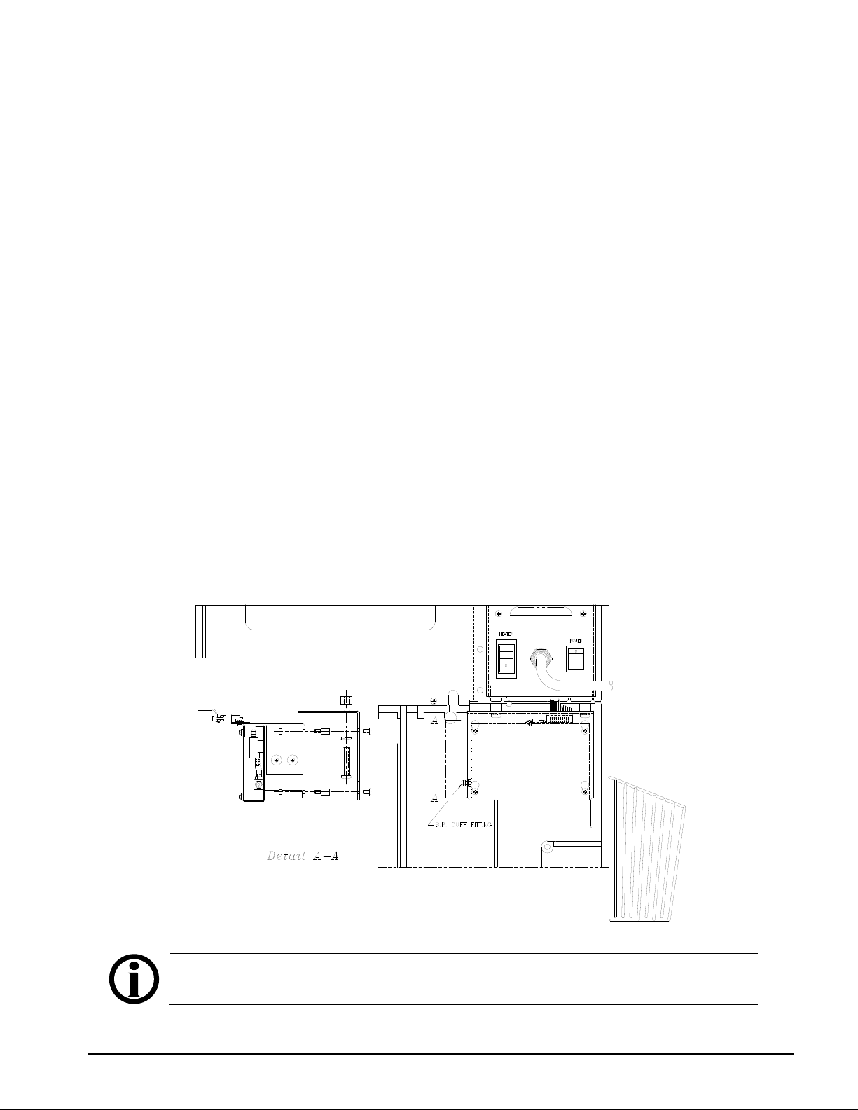
Section IV – Module Description
BLOOD PRESSURE MODULE
The blood pressure module utilizes an oscillometric method of obtaining an error free non-invasive
blood pressure measurement. The module contains an inflation pump, pressure relief valve, pressure
transducer and circuitry to measure systolic, diastolic pressures and heart rate (pulse rate). From the
systolic and diastolic pressures the mean Arterial Pressure (MAP) can be calculated.
The blood pressure module works in conjunction with the Blood Pressure screen where the
following parameters can be set:
Blood Pressure Alarm Limits
- Upper & Lower Systolic pressures
- Upper & Lower Diastolic pressures
- Upper & Lower Pulse rates
Blood Pressure Settings
- Inflation Pressure
- Interval between blood pressure readings
The module is attached to the machine cabinet with two screws and is located under the power
supply. The electrical connection to the card cage can be removed once the rear panel has been
removed. The blood pressure cuff tubing attaches directly to the module.
Note: Refer to the “Machine Specifications” section of the 2008T Operator’s
Manual (P/N 490122) for the blood pressure module specifications.
2008T Technician’s Manual – 490130 Rev. H IV-8
Page 53

Fresenius Medical Care North America
Manufactured by:
Fresenius USA, Inc.
4040 Nelson Avenue
Concord, CA 94520
800 227-2572
 Loading...