

Page 1

GESTRA Steam Systems
NRG 16-51
NRG 17-51
NRG 19-51
Installation Instructions 818956-02
Level Electrodes
NRG 16-51, NRG 17-51, NRG 19-51
EN
English
1
Page 2

2
Contents
Page
Application
Usage for the intended purpose ..............................................................................................................4
Function .................................................................................................................................................4
Directives and Standards
Pressure Equipment Directive (PED) 97/23/EC ........................................................................................
Functional Safety acc. to IEC 61508 ........................................................................................................
VdTÜV Bulletin “Wasserstand 100” (= Water Level 100) ..........................................................................
ATEX (Atmosphère Explosible) ................................................................................................................. 5
Technical Data
NRG 16-51, NRG 17-51, NRG 19-51 .......................................................................................................
Corrosion resistance ...............................................................................................................................7
Sizing .....................................................................................................................................................7
Name plate/ marking .............................................................................................................................. 8
Dimensions NRG 16-51, NRG 17-51 .......................................................................................................
Dimensions NRG 19-51 ........................................................................................................................10
Functional Elements
NRG 16-51, NRG 17-51, NRG 19-51 .....................................................................................................11
NRG 16-51, NRG 17-51, NRG 19-51 with four-pole connector ...............................................................
NRG 16-51F, NRG 17-51F, NRG 19-51F with aluminium terminal box ....................................................13
Key .......................................................................................................................................................14
Important Notes
Safety note ...........................................................................................................................................15
Scope of supply ....................................................................................................................................15
Installation
12
5
5
5
6
9
NRG 16-51, NRG 17-51, NRG 19-51, step 1 ..........................................................................................16
NRG 16-51, NRG 17-51, NRG 19-51, step 2 ..........................................................................................16
NRG 16-50F, NRG 17-50F, NRG 19-50, additional information ...............................................................16
Tools .....................................................................................................................................................17
Page 3

Contents – continued –
Page
Examples of Installation
NRG 16-51, NRG 17-51, NRG 19-51 ..................................................................................................... 18
Key .......................................................................................................................................................19
Electrical Connection
Connection of level electrode ................................................................................................................ 20
NRG 16-51, NRG 17-51, NRG 19-51 with four-pole connector ...............................................................20
NRG 16-51F, NRG 17-51F, NRG 19-51F with aluminium terminal box ....................................................20
Wiring diagram ..................................................................................................................................... 21
Key .......................................................................................................................................................22
Tools .....................................................................................................................................................22
Commissioning, Fault Indication and Remedy
NRG 16-51, NRG 17-51, NRG 19-51 .....................................................................................................
Decommissioning
Disposal................................................................................................................................................22
22
3
Page 4

4
Application
Usage for the intended purpose
The level electrodes NRG 16-51, NRG 17-51 and NRG 19-51 are used in conjunction with level switch
NRS 1-51 as high water level alarms for steam boiler plants and (pressurized) hot water installations.
A high level alarm prevents the water level from exceeding the preset max. water level (HW) and for this
purpose switches off e. g. the feedwater supply.
Function
When the level exceeds the max. water level, the level electrode enters the liquid and an alarm is
triggered in the level switch NRS 1-51. The switchpoint “High level (HW) exceeded” is dictated by the
length of the electrode rod.
The self-monitoring function ensures that an alarm will also be triggered if the electrode insulation is
contaminated or has developed a leak or if there is a malfunction in the electrical connection.
The level electrode is installed inside steam boilers, vessels or inlet lines of hot-water systems. The
protective tube mounted on site (see section Examples of Installation (pages 18, 19) ensures correct
functioning.
One level electrode NRG 1...-51 can be installed together with one GESTRA water level limiting
electrode in a single protection tube or external level pot.
If the level electrode is installed in a level pot outside the boiler, make sure that the connecting lines
are rinsed regularly. In addition, the logic unit SRL is required to monitor the purging times and the
purging sequence.
If the connecting lines for steam ≥ 40 mm and water ≥ 100 mm, the installation is considered to be
internal. In this case the rinsing processes do not have to be monitored.
Page 5

Directives and Standards
Pressure Equipment Directive (PED) 97/23/EC
The level electrode NRG 1...-51 in conjunction with level switch NRS 1-51 is EC type approved accord
ing to EN 12952/EN 12953. These Directives state, among other things, the requirements made on
limiting systems and equipment for steam boiler plants and (pressurised) hot-water installations.
Functional Safety acc. to IEC 61508
The level electrode NRG 1...-51 is certified acc. to IEC 61508 only if used in combination with level
switch NRS 1-51. This standard describes the functional safety of safety-related electrical/electronic/
programmable electronic systems.
The equipment combination NRG 1...-51 + NRS 1-50 corresponds to a type B subsystem with Safety
Integrity Level (SIL) 3.
VdTÜV Bulletin “Wasserstand 100” (= Water Level 100)
The level electrodes NRG 1-51, NRG 1...-12 in conjunction with the level switch NRS 1-51 are type
approved according to the VdTÜV Bulletin “Water Level 100”.
The VdTÜV Bulletin “Wasserstand (=Water Level) 100” specifies the requirements made on water level
control and limiting equipment for boilers.
ATEX (Atmosphère Explosible)
The level electrodes NRG 1...-51, NRG 1...-12 are simple items of electrical equipment as specified
in EN 60079-11 section 5.7. According to the European Directive 94/9/EC the equipment must be
equipped with approved Zener barriers if used in potentially explosive areas. Applicable in Ex zones
1, 2 (1999/92/EC). The equipment does not bear an Ex marking. The suitability of the Zener barriers is
certified in a separate document.
Note that the requirements of the IEC 61508 are not met if the NRG 1...-51, NRG 1...-12 + Zener
barriers + NRS 1-51 are interconnected!
-
5
Page 6

6
Technical Data
NRG 16-51, NRG 17-51, NRG 19-51
Service pressure
NRG 16-51: PN 40, 32 bar at 238 °C
NRG 17-51: PN 63, 46 bar at 260 °C
NRG 19-51: PN 160, 100 bar at 311 °C
Mechanical connection
Screwed ¾" to EN ISO 228-1
Materials
Sheath 1.4301 X5 CrNi18-10
Screw-in body 1.4571, X6CrNiMoTi17-12-2
Measuring electrode 1.4571 X6CrNiMoTi17-12-2
Electrode rod 1.4401 X5CrNiMo17-12-2
Electrode insulation PEEK
NRG 1...-51: Four-pole connector: polyamid (PA)
NRG 1...-51F: Terminal box 3.2161 G AlSi8Cu3
Lengths available
500 mm, 1000 mm, 1500 mm
Electrical connection
NRG 1...-51:
NRG 1...-50F: Terminal box made from aluminium, cable gland M 20
Protection
IP 65 to EN 60529
Max. admissible ambient temperature
70 °C
Weight
Approx. 1.2 kg (without extension)
(NRG 16-51, NRG 17-51, NRG 19-51)
Approx. 2.1 kg (without extension)
(NRG 16-51F, NRG 17-51F, NRG 19-51F)
Approvals
EC Prototype approval PED Pressure Equipment Directive 97/23/EC, EN 12952-11, EN 12953-09:
Requirements made on limiting equipment for boilers.
Functional Safety SIL 3 IEC 61508:
Functional safety of safety-related electrical/electronic/programmable
electronic systems
TÜV type approval VdTÜV Bulletin “Wasserstand 100” (= Water Level 100):
Requirements made on water level limiting & control equipment.
Type approval no. TÜV · SHWS · XX-423
(see name plate)
Four-pole connector, cable glands M 16
Gylon® is a registered trademark of Garlock Sealing Technologies, Palmyra NY, USA
Page 7

Technical Data – continued –
Corrosion resistance
If the equipment is used for the intended purpose, its safety is not impaired by corrosion.
Sizing
The body is not designed for pulsating loads. Welds and flanges are designed to withstand dynamic
loading (bending and alternative stress). The dimensional allowances and anti-corrosive additives
reflect the latest state of the technical art.
7
Page 8
8
Technical Data – continued –
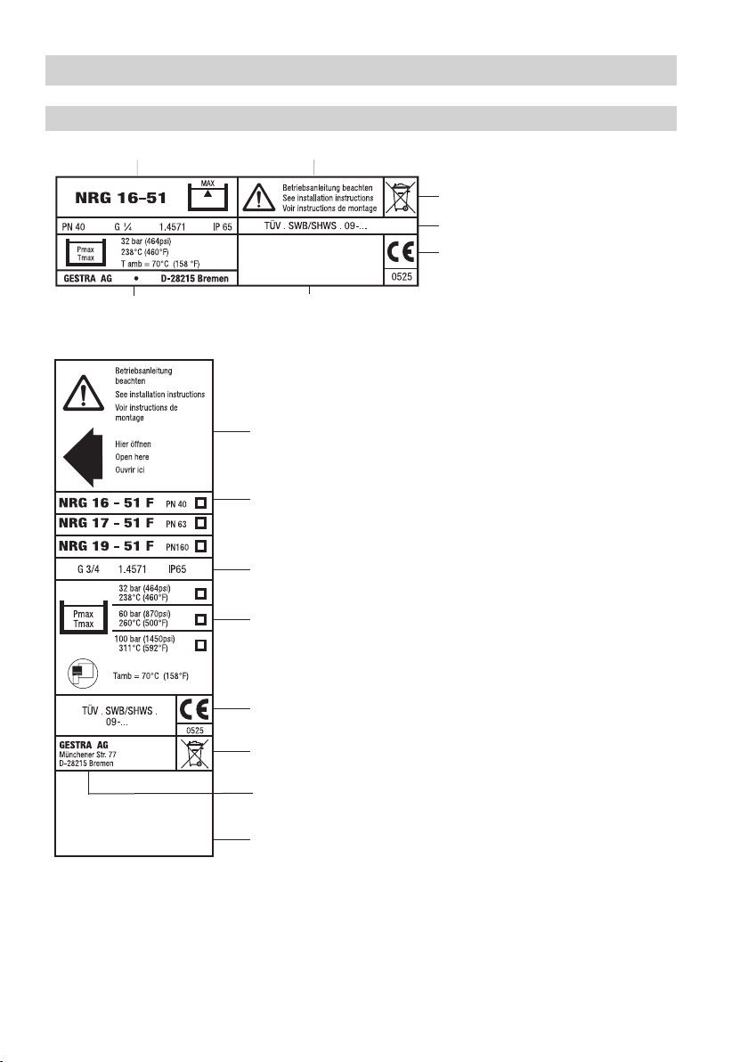
Name plate/marking
Equipment designation Safety note
Disposal note
Pressure rating, thread type,
material number, type approval number
CE marking
Fig. 1
Manufacturer
Serial number
Safety note
Equipment designation, pressure rating
Screwed connection, material number,
protection
Pressure/temperature rating
CE Marking, type approval
Disposal note
Manufacturer
Fig. 2
Serial number
Page 9

Technical Data – continued –
Dimensions NRG 16-51, NRG 17-51
175
140
b = 70
338≤ 1500
≤ 1500 90 272
Fig. 3
NRG 16-51, NRG 17-51
with four-pole connector
¾", DIN EN ISO 228-1
90
Fig. 4
NRG 16-51F, NRG 17-51F
with aluminium terminal box
9
Page 10

10
GESTRAStea mSystems
GESTRA
Technical Data – continued –
Dimensions NRG 19-51
175
140
b = 70
350
1", DIN EN ISO 228-1
140≤ 1500 284
140
1", DIN EN ISO 228-1
≤ 1500
Fig. 5
NRG 19-51
Fig. 6
NRG 19-51F
Page 11

Functional Elements
NRG 16-51, NRG 17-51, NRG 19-51
Fig. 7
1
2
3
4
6
Fig. 8
8
7
5
Fig. 9
NRG 16-50
NRG 17-50
NRG 19-50
Fig. 10
∅ 33
¾", DIN EN ISO 228-1
N 8
0.5
N 10
11
Page 12

12
Functional Elements – continued –
NRG 16-51, NRG 17-51, NRG 19-51 with four-pole connector
9
0
a
b
c
d
e
f
Fig. 11
Page 13

Functional Elements – continued –
NRG 16-51F, NRG 17-51F, NRG 19-51F with aluminium terminal box
Fig. 12
Fig. 13
j
g
h
i
k
13
Page 14

14
Functional Elements – continued –
Key
1 Measuring electrode
2 Bore
3 Spring
4 Electrode tip
5 NRG 1...-51: Joint ring 27 x 32, form D, DIN 7603, 1.4301, bright annealed
6 Seating surface
7 Electrode thread
8 Thermal insulation, provided on site, d = 20 mm (outside of thermal insulation of steam boiler)
9 Screw M 4
0 Cover
a Upper part of the terminal box
b Connecting plate
c Insulating plate
d Contact plate of level electrode
e Cable strain relief
f Cable gland M 16 (PG 9)
g Housing screws M 4
h Cable gland M 20 x 1.5
i Housing cover
j Nut
k Terminal strip
Page 15

Important Notes
Safety note
High water level alarms are safety devices and must only be installed, wired and commissioned by
qualified and competent staff.
Retrofitting and maintenance work must only be performed by qualified staff who – through adequate
training – have achieved a recognised level of competence.
Danger
When loosening the electrode steam or hot water might escape!
This presents the risk of severe scalding all over the body!
It is therefore essential not to dismantle the electrode unless the boiler pressure is
verified to be 0 bar.
The electrode becomes hot during operation.
Risk of severe burns to hands and arms.
Before carrying out installation and maintenance work make sure that the steam trap
is cold.
Attention
The name plate specifies the technical features of the equipment. Do not commission or
operate any item of equipment that does not bear its specific name plate.
Note
For outdoor installations please use level electrode NRG 1...-51 F. Level electrodes with
this suffix (F) feature a terminal box made from aluminium.
Scope of supply
NRG 16-51
1 Level electrode NRG 16-50, PN 40
1 Joint ring 27 x 32, Form D,
DIN 7603, 1.4301, bright annealed
1 Installation manual
NRG 17-51
1 Level electrode NRG 17-50, PN 63
1 Joint ring 27 x 32, Form D,
DIN 7603, 1.4301, bright annealed
1 Installation manual
NRG 19-51
1 Level electrode NRG 19-50, PN 160
1 Joint ring 27 x 32, Form D,
DIN 7603, 1.4301, bright annealed
1 Installation manual
15
Page 16

16
Installation
NRG 16-51, NRG 17-51, NRG 19-51, step 1
1. Screw electrode tip
2. Carefully determine required measuring length of electrode.
3. Mark length of electrode tip
4. Unscrew electrode tip
5. After visual inspection screw electrode tip
electrode tip 4 so that its end completely enters the small hole 2.
NRG 16-51, NRG 17-51, NRG 19-51, step 2
6. Check seating surfaces.
7. Place joint ring
8. Apply a light smear of silicone grease (e. g. WINIX
9. Screw level electrode into threads or flange provided on vessel and tighten with a 41 mm
open-end spanner.
The torque required when cold is 160 Nm.
Note
n One level electrode NRG 1...-51 can be installed together with one GESTRA water
NRG 16-50F, NRG 17-50F, NRG 19-50, additional information
One level electrode NRG 1...-51 F can be installed together with one GESTRA level electrode (with
aluminium terminal box) in a single protection tube or external level pot.
Please proceed as follows:
1. Mount level electrode NRG 1...-51F as first device as described in items 6 – 9.
When installing level electrode NRG 1...-51 F, please observe the following instructions:
1. Unscrew screws
towards this cover.
2. Loosen nut
3. Turn terminal box into desired position (+/–180°).
The terminal box can now be turned through +/– 180° .
4. Tighten nut
5. Mount housing cover
4 into measuring electrode 1. Fig. 7
4.
4 from measuring electrode 1 and cut tip.
4 into measuring electrode 1. Slide spring 3 along
Fig. 10
5 onto seating surface 6 of the electrode. Fig. 8
®
2150) to electrode thread 7.
level limiting electrode in a single protection tube or external level pot (inside diameter
100 mm).
Fig. 16.
g and remove housing cover i . Fig. 12. The arrow on the name plate points
j with a 19 mm spanner, but do not remove! Fig. 13
j with a torque of 25 Nm.
i and tighten screws g.
Page 17

Installation – continued –
Note
n For the approval of the boiler standpipe the relevant regulations must be considered.
n Refer to pages 18 for typical installation examples.
n The angle of inclination of the electrode must not exceed 45°, with the length of the
electrode rod being limited to 1000 mm.
n For outdoor installations please use level electrode NRG 1...-51 F. Level electrodes with
this suffix (F) feature a terminal box made from aluminium.
Attention
n The seating surfaces of the standpipe or the flange provided on the vessel must be
accurately machined, see
n Do not bend electrode tip when mounting.
n Use only the joint rings supplied with the electrode.
NRG 16-51, NRG 17-51, NRG 19-51: 27 x 32, form D, DIN 7603, 1.4301
n Do not lag electrode body above the hexgonal section.
n Do not insulate electrode thread with hemp or PTFE tape!
n Do not apply conductive paste or grease to the electrode thread!
n Make sure that the air distance between the electrode rod and earth (flange, vessel
wall) is not less than 14 mm.
n Observe the minimum distances for the installation of the electrode!
Fig. 15
Fig. 10
Fig. 14 – 17
Tools
n Open-end spanner A. F. 13, DIN 3110, ISO 3318
n Open-end spanner A. F. 19, DIN 3110, ISO 3318
n Open-end spanner A. F. 41, DIN 3110, ISO 3318
n Scriber
n Hacksaw
n Flat file, medium cut, DIN 7261, form A
17
Page 18

18
4
Examples of Installation
NRG 16-51, NRG 17-51, NRG 19-51
¾"
l
DN 50
s
o
m
∅ 20
n
20
p
q
10
≤ 90°
∅ 20
Fig. 14 Protection tube (provided on site) if electrode
is used as internal high level alarm.
¾"
¾"
t
u
l
m
45°
≥ 14
≥14
≥14
max. 1000
20
Fig. 15 Inclined installation, e. g. in ascending inlet
lines of hot-water installations or vessels
¾"
l
≥ DN 20
≤ 20
n
DN 100
24.5 24.5
∅ 20
20
n
o
10
≤ 90°
∅ 20
Fig. 16 Protection tube (provided on site) if electrode
is used as internal water level-limter
combined with water level control or
high water level alarm
≤ 3000
p
r
s
o
t
u
Centre distance
≥ 10
p
t
≥ DN 20
≥ DN 20
Fig. 17 Level pot if electrode is used as external
high level alarm.
Page 19

Examples of Installation – continued –
Key
l Flange PN 40, PN 63, PN 160, DN 50, DIN 2501-1 (for one electrode)
Flange PN 40, PN 63, PN 160, DN 100, DIN 2501-1 (for two electrodes)
m For the approval of the boiler standpipe with connecting flange the relevant
regulations must be considered.
n Vent hole Provide vent hole as close to the boiler wall as possible!
o High water HW
p Electrode rod d = 8 mm
q Protection tube DN 80 (in France according to AFAQ ≥ DN 100)
r Protection tube DN 100
s Electrode distance ≥ 14 mm (air gap and creepage distance)
t Low water LW
u Reducer DIN 2616-2, K-88.9 x 3.2 - 42.4 x 2.6 W
19
Page 20

20
Electrical Connection
Connection of level electrode
To connect the level electrode use screened multi-core control cable with a min. conductor size
0.5 mm2, e.g. LiYCY 4 x 0.5 mm2 .
Max. length 100 m with an electrical conductivity of the boiler water > 10 μS/cm at 25 °C.
Max. length 30 m with an electrical conductivity of the boiler water < 10 μS/cm at 25 °C.
Wire terminal strip in accordance with the wiring diagram. Fig. 18
Connect screens only to terminal 5 of the level switch NRS 1-51.
NRG 16-51, NRG 17-51, NRG 19-51 with four-pole connector
1. Undo screw 9. Fig. 12
2. Remove upper part
contact plate d.
3. Remove cover
4. Press connecting plate
The upper part of the terminal box can be turned in steps of 90°.
5. Detach cable gland
6. Run cable through cable gland
connecting plate b in accordance with wiring diagram. Fig. 19
7. Press connecting plate
8. Fix cable with cable clamp
9. Re-attach cover
10. Put upper part of the terminal box onto the level electrode and fix it with screw
a of the terminal box from the level electrode but leave insulating plate c on
0.
b out of upper part of the terminal box a.
f and cable clamp e from upper part of the terminal box a.
f and upper part of the terminal box a and wire terminals of the
b into the upper part of the terminal box and align cable.
e and cable gland f.
0 and insert screw 9.
9.
NRG 16-51F, NRG 17-51F, NRG 19-51F with aluminium terminal box
1. Unscrew screws
2. Undo cable gland
3. Remove terminal strip
4. Connect terminal strip according to the wiring diagram.
5. Attach terminal strip.
6. Tighten the cable gland in order to seal the cable entry.
7. Mount housing cover
g and remove housing cover i. Fig. 12
h. Pull cable through cable entry.
k from circuit board.
Fig. 20
i and tighten screws g.
Page 21

Electrical Connection – continued –
Wiring diagram
+ -
v
Fig. 18
Fig. 19 Wiring of level electrode
with four-pole connector
w
Terminal strip
NRS 1-51
Fig. 20 Wiring of level electrode with
aluminium terminal box
21
Page 22

22
Electrical Connection – continued –
Key
v Stand-by input 1, 24 V DC, for connecting the logic unit SRL
w Level electrode NRG 1...-51, NRG 1...-12
Tools
n Screwdriver for cross head screws, size 1
n Screwdriver for slotted screws, size 2.5, completely insulated according to DIN VDE 0680-1
n Open-end spanner A.F. 18 (19) mm
Commissioning, Fault Indication and Remedy
For additional information on commissiong procedures and troubleshooting refer to the installation
manual of the level switch NRS 1-51.
Decommissioning
Danger
Risk of severe burns and scalds to the whole body!
Before removing the level electrode make sure that the vessel or the external pot are
depressurised (0 bar) and cooled down to room temperature (20 °C).
Disposal
Dismantle the level electrode and separate the waste materials, using the specifications in the table
“Materials” as a reference.
For the disposal of the equipment observe the pertinent legal regulations concerning waste disposal.
If faults occur that are not listed above or cannot be corrected, please contact our service centre or
authorized agency in your country.
Page 23

For your Notes
23
Page 24

Agencies all over the world:
www.gestra.de
GESTRA
España
GESTRA ESPAÑOLA S.A.
Luis Cabrera, 86-88
E-28002 Madrid
Tel. 0034 91 / 5 15 20 32
Fax 0034 91 / 4 13 67 47; 5 15 20 36
E-mail: aromero@flowserve.com
Great Britain
Flowserve GB Limited
Abex Road
Newbury, Berkshire RG14 5EY
Tel. 0044 16 35 / 46 99 90
Fax 0044 16 35 / 3 60 34
E-mail: gestraukinfo@flowserve.com
Italia
Flowserve S.p.A.
Flow Control Division
Via Prealpi, 30
l-20032 Cormano (MI)
Tel. 0039 02 / 66 32 51
Fax 0039 02 / 66 32 55 60
E-mail: infoitaly@flowserve.com
Polska
GESTRA POLONIA Spolka z.o.o.
Ul. Schuberta 104
PL - 80-172 Gdansk
Tel. 0048 58 / 3 06 10 - 02
0048 58 / 3 06 10 - 10
Fax 0048 58 / 3 06 33 00
E-mail: gestra@gestra.pl
Portugal
Flowserve Portuguesa, Lda.
Av. Dr. Antunes Guimarães, 1159
Porto 4100-082
Tel. 00351 22 / 6 19 87 70
Fax 00351 22 / 6 10 75 75
E-mail: jtavares@flowserve.com
USA
Flowserve GESTRA U.S.
2341 Ampere Drive
Louisville, KY 40299
Tel. 001 502 / 267-2205
Fax 001 502 / 266-5397
E-mail: FCD-Gestra-USA@flowserve.com
GESTRA AG
P. O. Box10 54 60, D-28054 Bremen
Münchener Str. 77 , D-28215 Bremen
Telephone 0049 (0) 421 / 35 03- 0
Fax 0049 (0) 421 / 35 03 - 393
E mail gestra.ag@flowserve.com
Internet www.gestra.de
818956-02/05-2010cm (808823-02) · GESTRA AG · Bremen · Printed in Germany
24
 Loading...