

Page 1
USER INSTRUCTIONS
MX/DDC-100 Field Unit
FCD LMENIM2329-01 – 03/11
Installation
Operation
Maintenance
Experience In Motion
Page 2

MX/DDC-100 Field Unit Installation and Maintenance FCD LMENIM2329-01 – 03/11
MX/DDC-100 Field Unit Installation and Operation Manual
©2011 Copyright Limitorque. All rights reserved. Printed in the United States of America.
Disclaimer
This document is meant for use with MX Installation and Operation Manual for MX-05 through MX-40. Information
in this document is also applicable to MX-85 through MX-150. No part of this book shall be reproduced, stored in a
retrieval system, or transmitted by any means, electronic, mechanical, photocopying, recording, or otherwise without
the written permission of Limitorque. While every precaution has been taken in the preparation of this book, the
publisher assumes no responsibility for errors or omissions. Neither is any liability assumed for damages resulting
from the use of the information contained herein.
This document is the proprietary information of Limitorque, furnished for customer use ONLY. No other uses are
authorized without written permission from Limitorque.
Limitorque reserves the right to make changes, without notice, to this document and the product it describes.
Limitorque shall not be liable for technical or editorial errors or omissions made herein; nor for incidental and
consequential damages resulting from the furnishing, performance or use of this document.
The choice of system components is the responsibility of the buyer, and how they are used cannot be the liability of
Limitorque. However, Limitorque’s sales team and application engineers are always available to assist you in making
your decision.
This manual contains information that is correct to the best of Limitorque’s knowledge. It is intended to be a guide
and should not be considered as a sole source of technical instruction, replacing good technical judgment, since all
possible situations cannot be anticipated. If there is any doubt as to exact installation, configuration, and/or use, call
Limitorque at (434) 528-4400. The latest revisions to this document are available at www.flowserve.com.
2
Page 3

MX/DDC-100 Field Unit Installation and Maintenance FCD LMENIM2329-01 – 03/11
Contents
1 Introduction 5
1.1 Purpose 5
1.2 How to Use this Manual 5
1.3 User Safety 5
1.4 User Knowledge 6
1.5 DDC-100 System Capabilities and Features 6
1.6 General Specifications 7
2 System Components 8
2.1 Introduction 8
2.2 Hardware 8
2.2.1 MX Actuator 9
2.2.2 DDC–100 Field Unit 9
2.2.3 Host Controller 10
2.2.4 Master Station II 11
2.2.5 Network Cable 12
2.3 Software 13
2.3.1 Modbus Protocol 13
2.3.2 Modbus Function Codes 14
2.3.3 Modbus Function Code 01 (Read Coil Status) 14
2.3.4 Modbus Function Code 02 (Read Input Status) 15
2.3.5 Modbus Function Code 03 (Read Holding Register) 17
2.3.6 Modbus Function Code 04 (Read Input Register) 21
2.3.8 Modbus Function Code 06 (Preset Single Register) 23
2.3.9 Modbus Function Code 08 (Diagnostics) 26
2.3.10 Modbus Function Code 15 (Force Multiple Coils) 27
2.3.11 Modbus Function Code 16 (Preset Multiple Registers) 28
3 Installation and Configuration 30
3.1 Site and Network Cable Preparation 30
3.1.1 Site Preparation 30
3.1.2 Network Cable Preparation 30
3.2 Installation Verification 38
3.2.1 Network Cabling Installation Verification 38
3.2.2 Field Unit Installation Verification 38
3.3 Field Unit Configuration 39
3.3.1 Configuring Field Unit Parameters 39
3.4 Configuration Confirmation 44
3.4.1 Checking Connections 44
3.4.2 View Settings 44
3.4.3 Checking the Normal Display 44
4 Associated Documents 46
5 Troubleshooting 48
6 How to Order Parts 50
Appendix – Wiring Diagram 52
Appendix – MX/DDC Register Definitions 56
Appendix – Typical DDC-100 Network Installation Assignments 62
3
flowserve.com
Page 4

MX/DDC-100 Field Unit Installation and Maintenance FCD LMENIM2329-01 – 03/11
Figures
Figure 1.1 – Typical DDC-100 system with or without a Master Station II 6
Figure 2.1 – MX-05 actuator 8
Figure 2.2 – DDC-100 field unit 9
Figure 2.3 – Typical direct-to-host arrangement 10
Figure 2.4 – Typical Master Station II (rear view) 11
Figure 2.5 – Redundant connection operation in redundant host loop topology 12
Figure 3.1 – Network connections 30
Figure 3.2 – Removing outer plastic jacket 31
Figure 3.3 – Separating cable parts 32
Figure 3.4 – Stripping conductors 32
Figure 3.5 – Applying heat shrink tubing 33
Figure 3.6 – Ring tongue connectors 33
Figure 3.7 – Connecting network cable to MX terminal block 34
Figure 3.8 – Redundant bi-directional loop topology 36
Figure 3.9 – Daisy chain topology 37
Figure 3.10 – Error Messages 44
Figure A.1 (1 of 2) – Typical MX/DDC-100 wiring diagram 52
Figure A.1 (2 of 2) – Typical MX/DDC-100 wiring diagram 53
Figure A.2 - MX Terminal block 54
Tables
Table 2.1 – Modbus function codes supported 14
Table 2.2 – DDC-100 coil assignments, Modbus 05 command usage for digital outputs 14
Table 2.3 – Status Bit Definitions 15
Table 2.3 – Status Bit Definitions (continued) 16
Table 2.4 – Register definitions 18
Table 2.4 – Register definitions (continued) 19
Table 2.4 – Register definitions (continued) 20
Table 2.5 – DDC-100 coil assignments, Modbus 05 command usage for digital outputs 22
Table 2.6 – Modbus 06 command and field unit holding register 40001 24
Table 2.7 – Diagnostic Codes Supported by the DDC-100 Field Unit 27
Table 3.3 – Network cable terminations 34
Table 3.4 – MX/DDC digital input configurations (only one selection per row is permitted) 42
Table 3.5 – MX/DDC digital inputs (cross-reference of various inputs) 42
Table 3.6 – Digital input voltages 43
Table 3.7 – MX/DDC digital outputs S1-2 and R1-8 43
4
Page 5

1
MX/DDC-100 Field Unit Installation and Maintenance FCD LMENIM2329-01 – 03/11
Introduction
1.1 Purpose
This manual explains how to install and operate the Flowserve Limitorque MX™/DDC-100 field unit and is to be used
as an addendum to Bulletin FCD LMENIM2306, MX Electronic Actuator Installation and Operation Manual. Up to 250
actuators, each containing a DDC-100 field unit, may be connected by a single twisted-pair cable to form a DDC-100
network. This network permits the actuators to be operated by various control room devices such as a distributed
control system (DCS), a programmable logic controller (PLC), or a personal computer (PC). The DDC-100 system
communicates status and alarm data from each MX and valve.
1.2 How to Use this Manual
Each section provides the MX user with information on installing and operating the MX field unit.
Section 1 - Introduction
Details user safety and knowledge requirements, system capabilities, and features.
Section 2 - System Components
Focuses on the description of the DDC-100 system hardware and software components.
Section 3 - Installation and Configuration
Provides details for installing and configuring a field unit.
Section 4 - Associated Documents
Provides a list of documents on related subjects for additional MX and DDC-100 system information.
Section 5 - Troubleshooting
Section 6 - How to Order Parts
Appendix A - Wiring Diagram
Details wiring connections.
Appendix B - MX/DDC Register Definitions
Appendix C - Typicl DDC-100 Network Installation Assignments
1.3 User Safety
Safety notices in this manual detail precautions the user must take to reduce the risk of personal injury and damage
to the equipment. The user must read and be familiar with these instructions before attempting installation, operation,
or maintenance. Failure to observe these precautions could result in serious bodily injury, damage to the equipment,
warranty void, or operational difficulty. User must follow local and state safety regulations.
Safety notices are presented in this manual in three forms:
WARNING: c Refers to personal safety. Alerts the user to potential danger. Failure to follow warning notices could
result in personal injury or death.
CAUTION: a Directs the user’s attention to general precautions that, if not followed, could result in personal injury
and/or equipment damage.
NOTE: Highlights information critical to the user’s understanding of the actuator’s installation and operation.
flowserve.com
5
Page 6
MX/DDC-100 Field Unit Installation and Maintenance FCD LMENIM2329-01 – 03/11
1
2
34
5
250
.
.
.
Host controller
Optional
Master
Station
Network
RS-485
MX field
units
(up to 250)
1.4 User Knowledge
It is recommended that the user read this manual in its entirety before the DDC-100 equipped actuator is installed and
operated.
The user needs to have a fundamental knowledge of electronics and microprocessor concepts. An understanding of
valve actuators and digital control systems is beneficial to the field unit user.
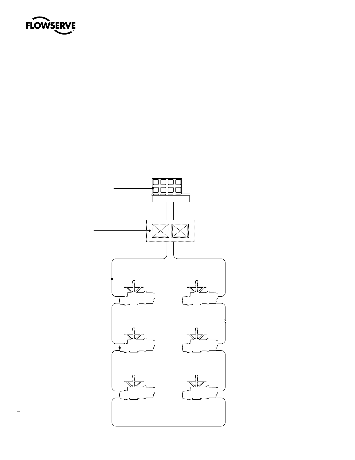
1.5 DDC-100 System Capabilities and Features
Limitorque’s distributed digital control (DDC) valve control network supports up to 250 actuators over a single
twisted-pair cable using Modbus™ protocol. MX actuators and other devices can be accessed from a control room
for integration with a plant asset management (PAM) system, distributed control system (DCS), programmable
logic controller (PLC), or personal computer (PC) based network. The DDC-100 system consists of a host system,
controller, network, and field units. A typical DDC-100 system is shown in Figure 1.1.
Figure 1.1 – Typical DDC-100 system with or without a Master Station II
6
Page 7

MX/DDC-100 Field Unit Installation and Maintenance FCD LMENIM2329-01 – 03/11
1.6 General Specifications
Direct-to-Host Specifications:
Direct connection to host controller•
Communicates using the Modbus protocol and the RS-485 electrical standards•
Configurable bitmap•
High-level surge protection on network•
Network Specifications:
Redundant bi-directional loop or daisy chain topology•
Modbus protocol and the RS-485 electrical standards•
High speed—up to 19.2 kbaud communications•
MX Field Unit Specifications:
“• OPEN,” “STOP,” and “CLOSE” commands
“• ESD” and “MOVE–TO” position commands
Actuator status and alarm messages•
Six digital inputs and two analog inputs for user (see • Table 2.2, Register Definitions)
Two surge-protected and mutually isolated communication channels•
MX local control panel configuration•
Torque output (for reference only) and position feedback•
User’s analog input feedback•
Nine digital outputs maximum (three standard/six optional)•
Master Station II (Optional) Specifications:
Supports all Limitorque DDC-100 field units: MX, L120, LY•
Controls up to 250 MOVs•
User-friendly touch panel operator interface:•
Permits configuration and control of DDC-100 network•
Configures communication to host or DCS (Distribution Control System)•
Password protected•
Optional Hot Standby Configuration: Automatically assumes control on Primary Master Failure or on command •
from the DCS or touch panel
Provides realtime status of field units through continuous cyclical polling•
Modbus RTU and TCP/IP:•
Addressable•
RS-232/485/422•
10/100 baseT•
Built-in Web server for ease of actuator and network diagnostics•
7
flowserve.com
Page 8
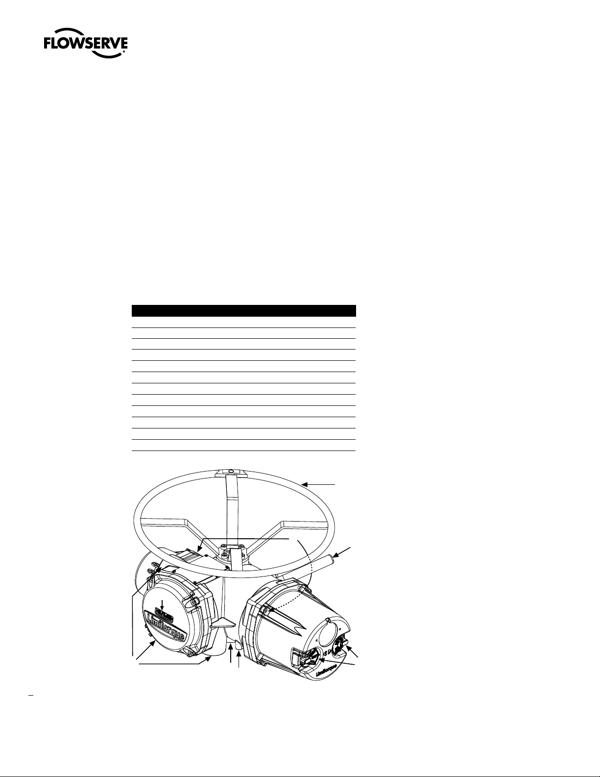
Piece Description
1 Handwheel
2 Declutch Lever
3 Oil Fills (dotted arrow depicts fill on declutch side)
4 Controls Compartment (field unit location)
5 LCD Display
6 Control Knobs
7 Ground Lug
8 Thrust/Torque Base
9 Conduit Entries
10 Terminal Compartment
11 Motor
12 Nameplate
1
2
3
7
8
4
5
11
12
10
6
9
2
MX/DDC-100 Field Unit Installation and Maintenance FCD LMENIM2329-01 – 03/11
System Components
2.1 Introduction
This section gives an overview of the components used in the DDC-100 system. The field unit is installed in each MX
actuator. The network cable connects the field unit to the network via the actuator terminal block. The network cable is
connected to a host controller or Master Station II.
2.2 Hardware
NOTE: Recommended storage procedures are detailed in Bulletin FCD LMENIM2314, MX Maintenance and Spare
Parts Manual. Failure to comply with recommended procedures will void the warranty. For longer-term storage,
contact Flowserve for procedures and recommendations.
Figure 2.1 – MX-05 actuator
8
Page 9

MX/DDC-100 Field Unit Installation and Maintenance FCD LMENIM2329-01 – 03/11
2.2.1 MX Actuator
The MX is a multi-turn valve actuator designed for operation of ON-OFF and modulating valve applications. This
actuator controls the opening and closing of valves. See Figure 2.1.
Features of the MX include:
Non-intrusive setup•
Separately sealed terminal chamber•
Absolute encoder for valve position sensing (no battery required) •
32-character graphical LCD display with 180° rotation •
Sophisticated electronic control, monitoring, and diagnostic capabilities with LimiGard™ technology •
2.2.2 DDC–100 Field Unit
The DDC-100 field unit is installed in the MX controls compartment. This unit permits the actuator to be controlled by
a host controller or Master Station II via the DDC-100 network. The field unit includes two high-level, surge-protected,
and isolated network communication channels, configurable digital I/O, and configuration via LCD screen. The
following commands and information may be transmitted over the DDC-100 network:
“• OPEN,” “STOP,” and “CLOSE” commands
“• ESD” and “MOVE–TO” position commands
Actuator status and alarm messages•
Six digital inputs and two analog inputs for user (see • Table 2.2, Register Definitions)
Two surge-protected and mutually isolated communication channels•
MX local control panel configuration•
Torque output (for reference only) and position feedback•
User’s analog input feedback•
Nine digital outputs maximum (three standard/six optional)•
Figure 2.2 – DDC-100 field unit
flowserve.com
9
Page 10
MX/DDC-100 Field Unit Installation and Maintenance FCD LMENIM2329-01 – 03/11
DCS PC/PAM PLC
1 250
52
3 4
RS-485
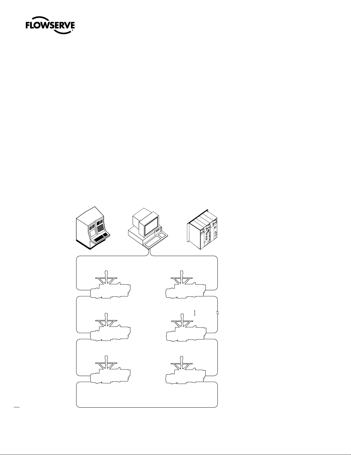
2.2.3 Host Controller
In the DDC-100 system, the network can be connected directly to a host controller without an interposing Master
Station II.
In this configuration, the host sends commands and messages to, and gathers responses from, the field units. The
commands and messages are sent via RS-485 data signals. The gathered responses are stored in a data table in the
host and are periodically updated by sequential polling of the field units. The host controls up to 250 field units. See
Section 3.1.2.3, Network Cable Connection to Host System or Master Station II.
When a host controller is used to directly communicate with the field units, i.e., direct-to-host communications, it
communicates using the Modbus protocol and the RS-485 electrical standard. This host controller can be one of the
following:
Distributed control system (DCS)•
Programmable logic controller (PLC) •
Personal computer (PC)•
Plant Asset Management (PAM) system•
Figure 2.3 – Typical direct-to-host arrangement
10
Page 11
MX/DDC-100 Field Unit Installation and Maintenance FCD LMENIM2329-00 – 2/08
o
l
FUSES
FUSES
l
o
ETHERNET
DO NOT USE
SINGLE
--
+
24VDC
PROPER OPERATION
INSIDE OF UNIT FOR
INPUT ONLY
EXTERNAL 24VDC
MOVE JUMPERS ON
250 V
INPUT
POWER
~1.5A
100-240VAC
ON
OFF
FUSES
2 AMP
DCS
DATA *
GND
CHANNEL B
PRINTER / DEBUG
WITH 110-240VAC
OPTIONAL
DO NOT USE
HOT STANDBY
GND
DATA *
DATA
DCS
PRINTER / DEBUG
ON
OFF
~1.5A
INPUT
100-240VAC
250 V
POWER
2 AMP
FUSES
--
+
24VDC
PROPER OPERATION
INSIDE OF UNIT FOR
INPUT ONLY
EXTERNAL 24VDC
MOVE JUMPERS ON
WITH 110-240VAC
CHANNEL A
DATA
NO SERVICEABLE PARTS INSIDE
1
2
3
5
4
6
9
7
8
10
2.2.4 Master Station II
A Master Station II may be used in the DDC-100 system. Master Station II’s are normally located in the control room,
and serve as the interface between the field units and the host controller. The following functions are provided:
Continuous polling of actuator network•
Message routing to/from field units •
Data concentration •
Data logging •
In this configuration, the Master Station II receives commands from a host controller. The Master Station II communicates with the host controller using the Modbus Protocol and the RS-232 or RS-485 electrical standard. See Bulletin
FCD LMENIM5001, DDC-100 Master Station II Installation and Operation Manual for details.
The Master Station II sends commands and messages to, and gathers responses from, the field units. The
commands and messages are sent via RS-485 data signals. The gathered responses are stored in a poll table in the
Master Station II and are periodically updated by sequential polling of the field units. The Master Station II controls up
to 250 field units. See Section 3.1.2.3, Network Cable Connection to Host System or Master Station II.
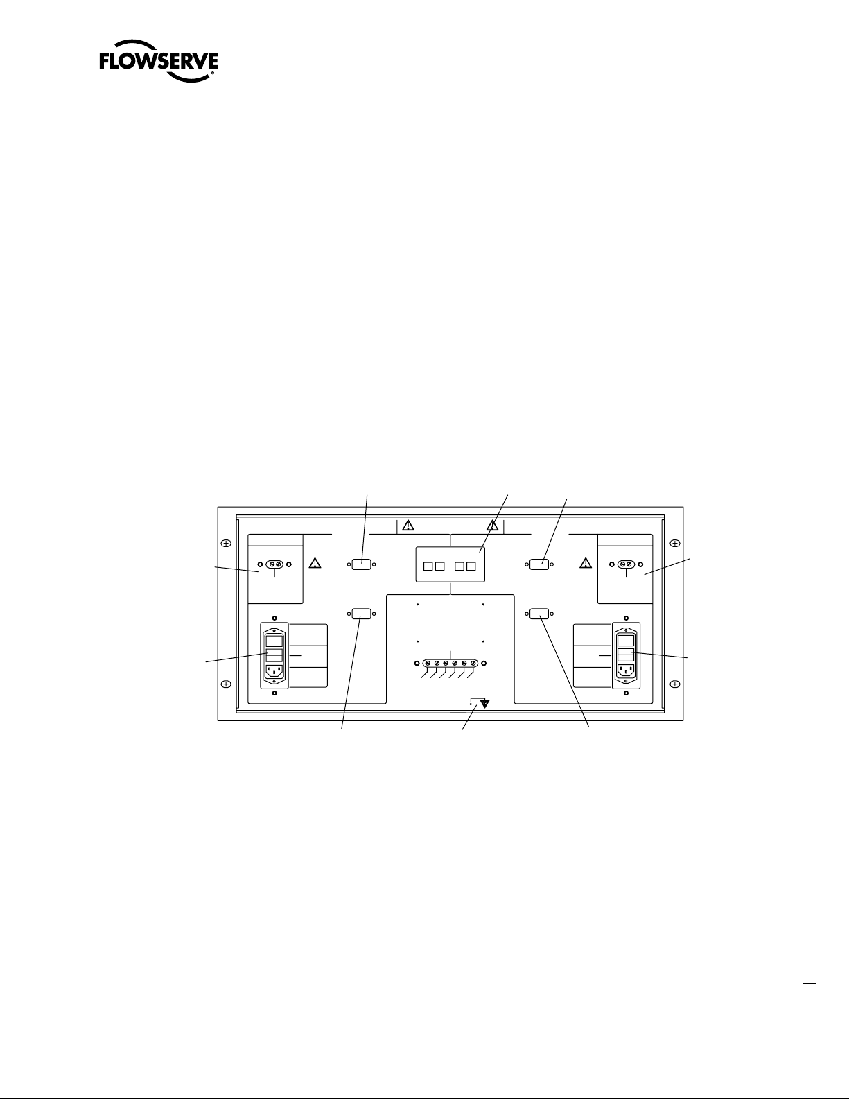
Figure 2.4 – Typical Master Station II (rear view)
1. Ethernet ports
2. Printer/Debug port
3. DCS port
4. Auxiliary 24 VDC power connection
5. Main power switch and connector for 120-240 VAC
6. Electrostatic ground
7. Hot Standby unit main power switch and connector for 120-240 VAC
8. Hot Standby auxiliary 24 VDC power connection
9. Hot Standby DCS Port
10. Hot Standby Printer/Debug Port
11
flowserve.com
Page 12
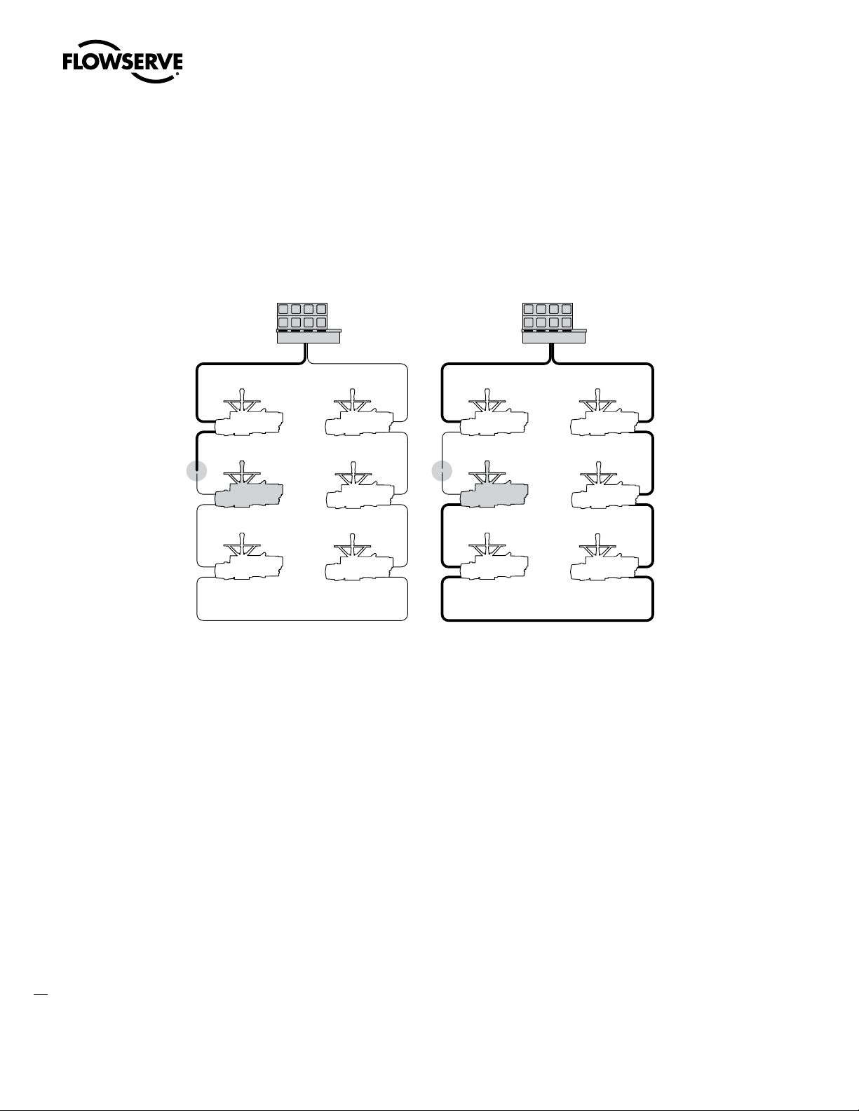
MX/DDC-100 Field Unit Installation and Maintenance FCD LMENIM2329-01 – 03/11
Signal initiated from host fails to reach
field unit which is located after fault...
Instead, signal routes to field unit using
other side of the loop cable and
completes connection.
2.2.5 Network Cable
The network consists of a shielded, twisted-pair cable that connects all field units and the host/Master Station II. The
cable is normally connected in a loop fashion so that any single break or short will not disable communication.
Figure 2.5 – Redundant connection operation in redundant host loop topology
12
The network cable connects the field units to the host controller or Master Station II. Belden 3074F, 3105A, or 9841
shielded, twisted-pair cable should be used. The use of other cables may result in a reduction of internodal distances
or increased error rate, and is the user’s responsibility.
Belden 3074F Specifications
Key Specifications
Total cable length between repeaters or nodes with repeaters, up to 19.2 kbps: 5000 ft (1.52 km) For loop •
mode, this is the total length between operating field units. If a field unit loses power, then the relays internal
to the field unit connect the A1 Channel to the A2 Channel, which effectively doubles the length of the cable
(assuming a single field unit fails). To ensure operation within specifications in the event of power failure to
field units, this consideration must be added. Example: To ensure operation within specification when any two
consecutive field units lose power, the maximum length of cable, up to 19.2 kbps, should not exceed 5000 ft
(1.52 km) per every four field units. See Section 3.1.2.3, Network Cable Connection to Host Controller or
Master Station II.
Resistance/1000 ft = 18 AWG (7 x 26) 6.92 ohms each conductor (13.84 ohms for the pair)•
Capacitance/ft = 14 pF (conductor-to-conductor)•
Capacitance/ft = 14 pF (conductor-to-shield)•
Page 13

MX/DDC-100 Field Unit Installation and Maintenance FCD LMENIM2329-01 – 03/11
Belden 3105A Specifications
Total cable length between repeaters or nodes with repeaters, up to 19.2 kbps: 4500 ft (1.37 km) For loop •
mode, this is the total length between operating field units. If a field unit loses power, then the relays internal
to the field unit connect the A1 Channel to the A2 Channel, which effectively doubles the length of the cable
(assuming a single field unit fails). To ensure operation within specifications in the event of power failure to
field units, this consideration must be added. Example: To ensure operation within specification when any two
consecutive field units lose power, the maximum length of cable, up to 19.2 kbps, should not exceed 4500 ft
(1.37 km) per every four field units. See Section 3.1.2.3, Network Cable Connection to Host Controller or
Master Station II.
Key Specifications
Resistance/1000 ft = 22 AWG (7 x 30) 14.7 ohms each conductor (29.4 ohms for the pair)•
Capacitance/ft = 11.0 pF (conductor-to-conductor)•
Capacitance/ft = 20.0 pF (conductor-to-shield)•
Belden 9841 Specifications
Total cable length between repeaters or nodes with repeaters: up to 19.2 kbps: 3500 ft (1 km) For loop mode, •
this is the total length between operating field units. If a field unit loses power, then the relays internal to the
field unit connect the A1 Channel to the A2 Channel, which effectively doubles the length of the cable (assuming
a single field unit fails). To ensure operation within specifications in the event of power failure to field units, this
consideration must be added. Example: To ensure operation within specification when any two consecutive
field units lose power, the maximum length of cable, up to 19.2 kbps, should not exceed 3500 ft (1 km) per
every four field units. See Section 3.1.2.3, Network Cable Connection to Host Controller or Master Station II.
Key Specifications
Resistance/1000 ft = 24 AWG (7 x 32) 24 ohms each conductor (48 ohms for the pair)•
Capacitance/ft = 12.8 pF (conductor-to-conductor)•
Capacitance/ft = 23 pF (conductor-to-shield)•
2.3 Software
2.3.1 Modbus Protocol
The Modbus protocol was developed by AEG Modicon® for communicating to various networked devices. The
relationship between these devices and a central controller is called a master-slave relationship in which the master
(host device) initiates all communication. The slave devices (DDC-100 field units in the actuators) respond to the
queries from the master.
Modbus only permits one device to communicate at any given time (simultaneous communication is prohibited) to
ensure process control integrity.
flowserve.com
13
Page 14

MX/DDC-100 Field Unit Installation and Maintenance FCD LMENIM2329-01 – 03/11
2.3.2 Modbus Function Codes
The controlling device (master) must conform to the Modbus protocol as defined in the Modbus-IDA Modbus
Application Protocol Specification V1.1a (http://www.Modbus-IDA.org) and support Modbus function codes 01
through 06, 08, 15, and 16. These function codes are a subset of the complete protocol and are defined in Table 2.1.
Table 2.1 – Modbus function codes supported
Extended
Function Bit/Register Addressing
Code Name Addressing Range
01 Read Coil Status Bit 0,000 - 9,999
02 Read Discrete Inputs Bit 10.000 - 19,999
03 Read Holding Register Register 40,000 - 49,999
04 Read Input Register Register 30,000 - 39,999
05 Force Single Coil Bit 0,000 - 9,999
06 Preset Single Register Register 40,000 - 49,999
08 Diagnostics N/A N/A
15 Force Multiple Coils Bit 0,000 - 9,999
16 Preset Multiple Registers Register 40,000 - 49,999
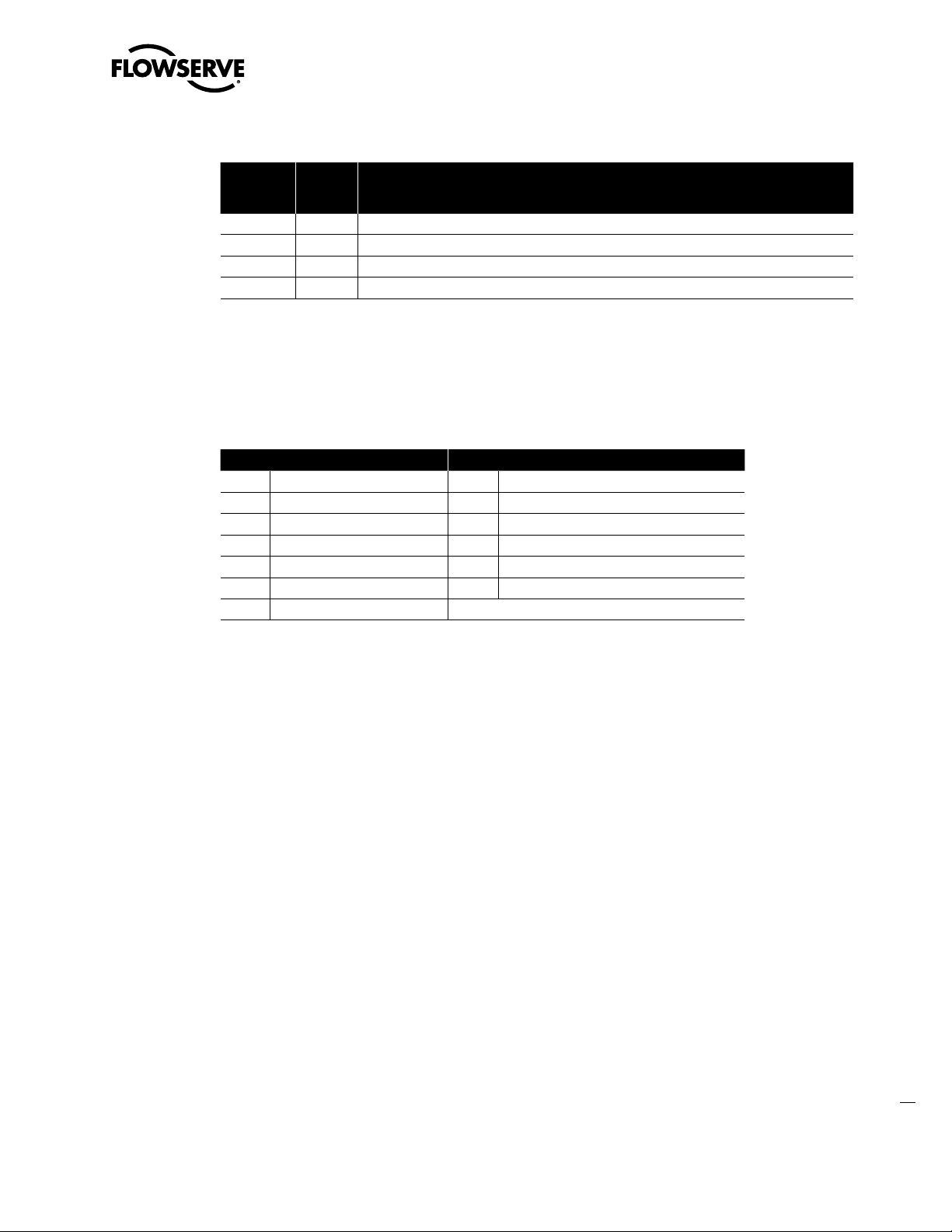
See Table 2.2 for a complete listing of MX/DDC holding registers.
2.3.3 Modbus Function Code 01 (Read Coil Status)
This function code is used to read the coil status in the DDC-100 Field Unit. There are nine coils available to be read
on DDC-100 Field Units as shown in Table 2.2. For the MX/DDC, Coil 1 indicates CLOSE contactor and is interlocked
with Coil 2, Coil 2 indicates OPEN contactor and is interlocked with Coil 1. When the I/O Module is used in non-MOV
(motor-operated valve) mode, relays 1 through 6 or coils 3 through 8 are available for user configuration.
Table 2.2 – DDC-100 coil assignments, Modbus 05 command usage for digital outputs
Coil Number Bit Number Function
1 00 Close/Stop
2 01 Open/Stop
3 02 S1 or R1 (Opt) Latched
4 03 S2 or R2 (Opt) Latched
5 04 R3 (Opt) Latched
6 05 R4 (Opt) Latched
7 06 R5 (Opt) Latched
8 07 R6 (Opt) Latched
9 08 R7 (Opt) Latched
10 09 R8 (Opt) Latched
The normal response to the (05) command is an echo of the command.
Example
Poll field unit number 3 for 8 coils starting at coil 1.
Query: 0301000000083C2E
14
Response: 03010118503A
Page 15

MX/DDC-100 Field Unit Installation and Maintenance FCD LMENIM2329-01 – 03/11
Message Breakdown
Query Response
03 Slave (Field Unit) Address 03 Slave (Field Unit) Address
01 Function 01 Function
00 Starting Address Hi 01 Byte Count
00 Starting Address Lo 18
00 No. of Points Hi 503A Error Check (CRC)
08 No. of Points Lo
3C2E Error Check (CRC)
Note 1: 18h equals 00011000 or coils 4 and 5 are ON.
1
Data (Coils 8 - 1)
2.3.4 Modbus Function Code 02 (Read Input Status)
This function code is used to read the discrete input status bits in the DDC-100 Field Unit. The use of this function
code will provide the user with the input status bits that are used to develop holding registers 9 through 13. The
status bit inputs are contained in locations 10129-10208 for each DDC-100 Field Unit and are defined in Table 2.3.
Table 2.3 – Status Bit Definitions
Bit Number
129 128 Opened
130 129 Closed
131 130 Stopped in mid-travel
132 131 Opening
133 132 Closing
134 133 Valve jammed
135 134 Not in remote
136 135 Combined fault
137 136 Over-temperature fault
138 137 Actuator failing to de-energize
139 138 Channel A fault
140 139 Channel B fault
141 140 Open torque switch fault
142 141 Close torque switch fault
143 142 Valve operated manually fault
144 143 Phase error
145 144 Open inhibit active
146 145 Close inhibit active
147 146 Not used
148 147 Not used
149 148 One or more phases is missing
150 149 Reverse phase sequence is occurring
151 150 ESD conflict
152 151 Inhibit conflict
153 152 Use in local/stop (input must be set for CSE and enabled)
154 153 Not used
155 154 Network emergency shutdown (ESD) is active
156 155 Local emergency shutdown is active
Modbus
Bit
Address
MX/DDC
15
flowserve.com
Page 16

16
MX/DDC-100 Field Unit Installation and Maintenance FCD LMENIM2329-01 – 03/11
Table 2.3 – Status Bit Definitions (continued)
Bit Number
157 156 Field unit microprocessor has reset since the last poll
158 157 MX in stop move
159 158 Opening in local mode
160 159 Closing in local mode
161 160 Close contactor (interlocked)
162 161 Open contactor (interlocked)
163 162 S1 or R1 (opt)
164 163 S2 or R2 (opt)
165 164 R3 (opt)
166 165 R4 (opt)
167 166 R5 (opt)
168 167 R6 (opt)
169 168 R7 (opt)
170 169 Network relay
171 170 R8 (opt)
172 171 Not used
173-176 172-175 Mov series (0=1, A=9)
177 176 Remote switch
178 177 Thermal overload
179 178 Open torque switch
180 179 Open limit switch
181 180 Close torque switch
182 181 Close limit switch
183 182 Not used
184 183 Not used
185 184 User Input 0
186 185 User Input 1
187 186 User Input 2
188 187 Remote stop input
189 188 Remote open input
190 189 Remote close input
191 190 Not used
192 191 Not used
193 192 Analog board 1 present
194 193 Analog board 2 present
195 194 Analog Input #1 lost
196 195 Analog Input #2 lost
197 196 Network Channels A/B timed out
198 197 Relay board R5-R8 present
199 198 DDC board present
200 199 Relay board R1-R4 and RM present
201 200 FF board present
202 201 PB PA board present
203 202 CLE assigned for input 2
204 203 DNET board present
Modbus
Bit
Address
MX/DDC
Page 17
MX/DDC-100 Field Unit Installation and Maintenance FCD LMENIM2329-01 – 03/11
Table 2.3 – Status Bit Definitions (continued)
Bit Number
205 204 Lost Phase Input
206 205 Phase Reverse Input
207 206 Not used
208 207 PB DP board present
Example
Poll field unit number 22 for 16 inputs starting at input 129 with the actuator opening.
Query: 1602008000107B09
Response: 1602020108CDED
Message Breakdown
Query Response
16 Slave (Field Unit) Address 16 Slave (Field Unit) Address
02 Function 02 Function
00 Starting Address Hi 02 Byte Count
80 Starting Address Lo 01
00 No. of Points Hi 08
10 No. of Points Lo CDED Error Check (CRC)
7B09 Error Check (CRC)
Note 1: 01h equals 0000 0001 (actuator open input bit is ON).
Modbus
Bit
Address
MX/DDC
1
Data (Inputs 10136 - 10129)
2
Data (Inputs 10144 - 10137)
Note 2: 08h equals 0000 1000 (actuator Channel B Fail bit is ON).
2.3.5 Modbus Function Code 03 (Read Holding Register)
This function code is used to read the binary contents of holding registers in the DDC-100 Field Unit. This function
code is typically used during the network polling cycle. A network poll should consist of field unit registers 9 (Status)
and 10 (Fault) as a minimum. Holding register 8 should also be polled when the actuator is configured for the analog
feedback option or position control. See Table 2.4 for a complete listing of the holding registers.
17
flowserve.com
Page 18

MX/DDC-100 Field Unit Installation and Maintenance FCD LMENIM2329-01 – 03/11
Table 2.4 – Register definitions
Register # Description Meaning
1 Command Registers 1 and 2 are write-only registers used for Modbus
Function Code 06
2 Argument Registers 1 and 2 are write-only registers used for Modbus
Function Code 06
3 Analog Output 1 Analog Output 1 Value (Default 0-100)
4 Analog Output 2 Analog Output 2 Value (Default 0-100)
5 Analog Input Main Power (Volts)
6 Analog Input Analog Input 1 (Default 0-100)
7 Analog Input Analog Input 2 (Default 0-100)
8 Position Valve Position, Scaled Value (Default 0-100)
9 Status Register 16 Bits of field unit status:
Bit 0 Opened
Bit 1 Closed
Bit 2 Stopped in Mid-Travel
Bit 3 Opening
Bit 4 Closing
Bit 5 Valve jammed
Bit 6 Not in Remote
Bit 7 Combined fault
2
3
Bit 8 Over temperature fault
Bit 9 Future Implementation
Bit 10 Network Channel A fault
Bit 11 Network Channel B fault
Bit 12 Open torque switch fault
Bit 13 Close torque switch fault
Bit 14 Valve-operated manually fault
Bit 15 Phase error
NOTE 1: Default value is scaled 0-100 of span. Changes made to “Analog Scale” affect analog registers (3, 4, 6, 7, 8)
and “move-to” commands. (0-100, 0-255, 0-4095)
1
1
1
User 4-20 mA / 0-20 mA Input
1
User 4-20 mA / 0-20 mA Input
4
(Terminals 5 and 4)
4
(Terminals 13 and 14)
1
18
NOTE 2: MX/DDC actuators shipped after 2nd QTR, 1999, have the following definition of Register 9 Bit 6. When this
bit has a value of 1 or true, the actuator is in LOCAL or STOP (unavailable for network control). The actuator
selector switch in REMOTE (available for network control) is indicated by Register 12 Bit 0 having a value of 1
or true.
IMPORTANT: Verify host program when installing an MX/DDC actuator shipped after 2nd QTR, 1999, on a network
commissioned before 2nd QTR, 1999, for proper indication of selector switch values. Failure to verify proper selector
switch indication at the host may cause unsafe conditions at the facility.
MX/DDC actuators shipped prior to 2nd QTR, 1999, have the following definition for Register 9 Bit 6. When this bit has
a value of 1 or true, the actuator selector switch is in LOCAL mode. This bit does not indicate STOP or REMOTE. The
actuator selector switch in REMOTE (available for network control) is indicated by Register 12 Bit 0 having a value of 1
or true. Register 9 Bit 6 value 0 (zero) or false AND Register 12 Bit 0 value 0 (zero) or false indicates selector switch is
in the STOP position.
NOTE 3: Combined Fault bit is high when Bit 5 or 8 or 9 or 15 or (Bits 10 and 11) is high.
NOTE 4: Channel A is physical connection A1. Channel B is physical connection A2. (See Appendix A.)
Page 19

MX/DDC-100 Field Unit Installation and Maintenance FCD LMENIM2329-01 – 03/11
Table 2.4 – Register definitions (continued)
Register # Description Meaning
10 Fault Register 16 Bits of field status
Bit 0 Open inhibit active
Bit 1 Close inhibit active
Bit 2 Not Used
Bit 3 Not Used
Bit 4 One or more phases are missing
Bit 5 Reverse phase sequence is occurring
Bit 6 ESD conflict
Bit 7 Inhibit conflict
Bit 8 CSE in local/stop (input must be set for CSE and enabled)
Bit 9 Not Used
Bit 10 Network emergency shutdown is active
Bit 11 Local PB emergency shutdown is active
Bit 12 Field unit microprocessor has reset since the last poll
Bit 13 MX in stop mode
Bit 14 Opening in local mode
Bit 15 Closing in local mode
11 Digital Outputs Value of 16 Digital Outputs
Bit 0 Close contactor (Interlocked)
Bit 1 Open contactor (Interlocked)
Bit 2 S1 or R1 (Opt)
Bit 3 S2 or R2 (Opt)
Bit 4 R3 (Opt)
Bit 5 R4 (Opt)
Bit 6 R5 (Opt)
Bit 7 R6 (Opt)
Bit 8 R7 (Opt)
Bit 9 Network Relay
Bit 10 R8 (Opt)
Bit 11 Not Used
BIT 12-15 MOV Series (0 = 1, A = 9)
12 Digital Inputs 1 Value of 16 Digital Inputs
Bit 0 Remote Switch
Bit 1 Thermal Overload
Bit 2 Open Torque Switch
Bit 3 Open Limit Switch
Bit 4 Close Torque Switch
Bit 5 Close Limit Switch
Bit 6 Not Used
Bit 7 Not Used
Bit 8 User Input 0 (Default=ESD), Terminal 30
Bit 9 User Input 1 (Default=Open Inhibit), Terminal 34
Bit 10 User Input 2 (Default=Close Inhibit), Terminal 35
Bit 11 Remote Stop Input, Terminal 26
Bit 12 Remote Open Input, Terminal 25
Bit 13 Remote Close Input, Terminal 27
Bits 14-15 Not Used
flowserve.com
19
Page 20

MX/DDC-100 Field Unit Installation and Maintenance FCD LMENIM2329-01 – 03/11
Table 2.4 – Register definitions (continued)
Register # Description Meaning
13 Digital Inputs 2 Value of 16 Digital Inputs
Bit 0 Analog board 1 present
Bit 1 Analog board 2 present
Bit 2 Analog Input 1 lost
Bit 3 Analog Input 2 lost
Bit 4 Network Channels A/B timed out
Bit 5 Relay board R5-R8 present
Bit 6 DDC board present
Bit 7 Relay board R1-R4 and RM present
Bit 8 Foundation Fieldbus board present
Bit 9 Profibus PA board present
Bit 10 CSE chosen for input 2
Bit 11 DeviceNet board present
Bit 12 Phase lost
Bit 13 Phase reverse
Bit 14 Not Used
Bit 15 Profibus DP board present
14 Timers and Analog Channels Internal compartment temperature
15 User Faults Bits 0-15 Not Used
16 Current State Bits 0-15 Not Used
17 Field Unit Holding Register Special Applications Only
18 Field Unit Holding Register Special Applications Only
19 Field Unit Holding Register Special Applications Only
20 Field Unit Holding Register Special Applications Only
21 Field Unit Holding Register Special Applications Only
22 Field Unit Holding Register Special Applications Only
23 Field Unit Holding Register Special Applications Only
24-44 Reserved Special Applications Only
45-47 Not Named Special Applications Only
48 TP_START_POSITION Special Applications Only
49 TP_STOP_POSITION Special Applications Only
50 TP_SAMPLE Special Applications Only
51 TP_MID_T_HIGH Special Torque Applications Only
52 TP_MID_T_POS Special Applications Only
53 TP_MID_T_AV_VAL Special Torque Applications Only
54 TP_STOP_VAL Special Applications Only
55 TP_BEFORE_ MID_T_HIGH Special Torque Applications Only
56 TP_AFTER_ MID_T_HIGH Special Torque Applications Only
Note 1: Range is +90°C to -55°C. High byte 00 indicates positive (+) and 01 indicates negative (-). Low byte indicates temperature
value.
Example: 0x0019 = +25°C
0x011E = -30°C
1
20
Example
Poll field unit number 125 for 3 registers starting at register 8 with the actuator stopped between the limits and in
local mode.
Query: 7D0300070003BFF6
Response: 7D0306003D084400003E07
Page 21

MX/DDC-100 Field Unit Installation and Maintenance FCD LMENIM2329-01 – 03/11
Message Breakdown
Query Response
7D Slave (Field Unit) Address 7D Slave (Field Unit) Address
03 Function 03 Function
00 Starting Address Hi 06 Byte Count
07 Starting Address Lo 00 Data Hi (Register 40008)
00 No. of Points Hi 3D
03 No. of Points Lo 08 Data Hi (Register 40009)
BFF6 Error Check (CRC) 44
Note 1: 003Dh equals 61 Decimal (actuator Analog Input 1 in percent format).
Note 2: 0844h equals 2116 Decimal or 0000 1000 0100 0100 Binary (actuator stopped between limits,
local mode, and Channel B Fail bit is ON).
1
2
00 Data Hi (Register 40010)
00 Data Lo (Register 40010)
3E07 Error Check (CRC)
Data Lo (Register 40008)
Data Lo (Register 40009)
2.3.6 Modbus Function Code 04 (Read Input Register)
This function code is used to read the binary contents of input registers in the DDC-100 Field Unit. The typical use
of this function code is to read the analog input registers. If the field unit is configured for scaled analog data, the
register information will be returned as a percent from 0 to 100 (see NOTE below). The first analog input register
(Analog 4) will start at register 30005 through (Analog 1) Input Register 30008.
This function code may also be used to read the information available in registers 9 through 16.
NOTE: Limitorque field units can be configured to report analog data in several formats. See the appropriate field unit
manual for details.
Example
Poll field unit number 70 for 4 registers starting at register 5 (Analog Input Registers 1-4).
(This example assumes that the field unit is configured for scaled analog data.)
Query: 460400040004BF7F
Response: 460408FFFFFFFF002B001EDBA8
flowserve.com
21
Page 22

MX/DDC-100 Field Unit Installation and Maintenance FCD LMENIM2329-01 – 03/11
Message Breakdown
Query Response
46 Slave (Field Unit) Address 46 Slave (Field Unit) Address
04 Function 04 Function
00 Starting Address Hi 08 Byte Count
04 Starting Address Lo FF Data Hi (Register 40005)
00 No. of Points Hi FF
04 No. of Points Lo FF Data Hi (Register 40006)
BF7F Error Check (CRC) FF
Note 1: FFFFh equals 65535 Decimal (actuator Analog Input 4 value).
Note 2: FFFFh equals 65535 Decimal (actuator Analog Input 3 value).
Note 3: 002Bh equals 43 Decimal (actuator Analog Input 2 value).
Note 4: 001Eh equals 30 Decimal (actuator Analog Input 1 in percent format).
1
Data Lo (Register 40005)
2
Data Lo (Register 40006)
00 Data Hi (Register 40007)
3
2B
00 Data Hi (Register 40008)
1E
DBA8 Error Check (CRC)
Data Lo (Register 40007)
4
Data Lo (Register 40008)
2.3.7 Modbus Function Code 05 (Force Single Coil)
This function code is used to force a single coil in the DDC-100 Field Unit. Forcing the individual coil either ON (1) or
OFF (0) will energize or de-energize a coil (digital output) in the field unit. Coil 1 in the field unit closes the actuator
and Coil 2 opens the actuator. If the actuator is opening or closing, changing the status of coil 1 or 2 from a value of
1 to 0 will stop the actuator (the coil will automatically be set to zero when the actuator reaches the full open or full
close position).
Available digital outputs for DDC-100 Field Units are listed in Table 2.5. Force-coil commands should be issued
only once for the desired field unit control. Repeated issuance of an acknowledged command will degrade network
performance.
NOTE: See Bulletin LMAIM1329, Accutronix Installation and Operation for MX-DDC Field Unit to configure AS and
AR Relays for DDC control.
Table 2.5 – DDC-100 coil assignments, Modbus 05 command usage for digital outputs
Coil Number Bit Number Function
1 00 Close/Stop
2 01 Open/Stop
3 02 S1 or R1 (Opt) Latched
4 03 S2 or R2 (Opt) Latched
5 04 R3 (Opt) Latched
6 05 R4 (Opt) Latched
7 06 R5 (Opt) Latched
8 07 R6 (Opt) Latched
9 08 R7 (Opt) Latched
10 09 R8 (Opt) Latched
The normal response to the (05) command is an echo of the command.
22
Page 23

MX/DDC-100 Field Unit Installation and Maintenance FCD LMENIM2329-01 – 03/11
Example of force coil command
Force coil 1 of field unit 49 ON. This will CLOSE the valve controlled by field unit 49.
Query: 31050000FF0089CA
Response: 31050000FF0089CA
Message Breakdown
Query Response
31 Slave (Field Unit) Address 31 Slave (Field Unit) Address
05 Function 05 Function
00 Coil Address Hi 00 Coil Address Hi
1
00
FF Force Data Hi FF Force Data Hi
2
00
89CA Error Check (CRC) 89CA Error Check (CRC)
Note 1: 0000h equals Coil Address 00000001 (field unit coil 1).
0001h equals Coil Address 00000010 (field unit coil 2).
Note 2: FF00h requests the coil to be ON. (0000h requests the coil to be OFF)
Coil Address Lo 00 Coil Address Lo
Force Data Lo 00 Force Data Lo
2.3.8 Modbus Function Code 06 (Preset Single Register)
This function code is used to preset a single register in the field unit. The function code is typically used to command
the DDC-100 Field Unit by writing values to the 40001 and 40002 registers. A predetermined value may be used to
open/stop/close the actuator, move the actuator to a preset position, activate/deactivate network ESD, reset the field
unit, etc.
The Modbus function code 06 is also used to command a throttling actuator to “move-to” a position of 0-100% of
open. The field unit will compare the new position value with the current position and open or close the valve to meet
the new position requirement. This is a two-step command: the first step is to write the desired position value to the
field unit register 40002, then write the value of 6656 to field unit register 40001. This sequence of commands loads
the desired position, then instructs the field unit to execute the command.
For field units containing Modbus Firmware 2.00 or greater and MX-DDC field units containing Firmware 02/01.00 or
greater, the “move-to” command may be executed with a one-step command.
Modbus function code 06 command values for controlling the DDC-100 Field Unit are given in Table 2.6. Each
command should be issued only one time for the desired field unit control. Repeated issuance of an acknowledged
command will degrade network performance.
The normal response to the (06) command is an echo of the command.
NOTE:
1) Only use values listed in Table 2.6 For field unit register 40001.
2) Field Unit Register 40002 should only be used for “move-to” position input.
3) The Host MUST issue “move-to” commands in the proper sequence. Failure to issue this two-step command
in the correct sequence will result in the field unit waiting for the proper command sequence execution before
performing the “move-to” function.
4) The “move-to” command should only be used with field units that include the position control option.
5) Do not write to Field Unit Registers 5-16.
flowserve.com
23
Page 24

MX/DDC-100 Field Unit Installation and Maintenance FCD LMENIM2329-01 – 03/11
Table 2.6 – Modbus 06 command and field unit holding register 40001
Host Commands to Field Unit Register 1 Value (Decimal) Function
Null Command 0 No action
Open 256 Open actuator
Stop 512 Stop actuator
Close 768 Close actuator
Reset Field Unit 1024 Reset processor
Start Network ESD 1280 ESD initiate
Stop Network ESD 1536 ESD terminate
Engage Relay #1 2304 S1 or R1 (opt)
Engage Relay #2 2560 S2 or R2 (opt)
Engage Relay #3 2816 R3 (opt)
Engage Relay #4 3072 R4 (opt)
Engage Relay #5 3328 R5 (opt)
Engage Relay #6 3584 R6 (opt)
Engage Relay #7 3840 R7 (opt)
Disengage Relay #1 4352 S1 or R1 (opt)
Disengage Relay #2 4608 S2 or R2 (opt)
Disengage Relay #3 4864 R3 (opt)
Disengage Relay #4 5120 R4 (opt)
Disengage Relay #5 5376 R5 (opt)
Disengage Relay #6 5632 R6 (opt)
Disengage Relay #7 5888 R7 (opt)
Move-To (Enable)
Engage Relay #8 6912 R8 (opt)
Disengage Relay #8 7168 R8 (opt)
Note 1: This is a two-step command. A valid value must be written to Register 2 before issuing this command.
(See Note 1 of Table 2.2.)
Other registers may also be preset to control or change other functions but care must always be taken to properly
change these values. An improper value written to a register can cause undesirable actions from the DDC-100 Field
Unit.
1
6656 Initiates “move-to”
24
NOTE: Null Command–The field unit takes no action when this command is received. This command is typically used
by a Host to reset the Host output register when required.
Example of Field Unit Command
Write the command to open an actuator (actuator open) to field unit number 179. This corresponds to writing the
value 256 into field unit register 40001.
Query: B306000001009388
Response: B306000001009388
Message Breakdown
Query Response
B3 Slave (Field Unit) Address B3
06 Function 06 Function
00 Register Address Hi 00 Register Address Hi
1
00
01 Force Data Hi 01 Preset Data Hi
2
00
9388 Error Check (CRC) 9388 Error Check (CRC)
Note 1: 0000h equals Register Address 40001 (field unit register 1, command register).
Note 2: 0100h requests the register to be preset with 256 Decimal (engage open contactor).
Register Address Lo 00 Register Address Lo
Force Data Lo 00 Preset Data Lo
Slave (Field Unit)
Address
Page 25

MX/DDC-100 Field Unit Installation and Maintenance FCD LMENIM2329-01 – 03/11
Example of “Move-To” Command
Move an actuator at address 179 to 42% of open by first writing the value of 42 to the field unit 40002 register. After
receiving a response from the field unit, write the value of 6656 to the field unit 40001 register. The actuator will then
move to a position of 42% of open.
First Command
Query: B3060001002A4207
Response: B3060001002A4207
First Command Message Breakdown
Query Response
B3 Slave (Field Unit) Address B3
06 Function 06 Function
00 Register Address Hi 00 Register Address Hi
1
01
00 Force Data Hi 00 Preset Data Hi
2
2A
4207 Error Check (CRC) 4207 Error Check (CRC)
Note 1: 001h equals Register Address 40002 (field unit register 2, argument register).
Register Address Lo 01 Register Address Lo
Force Data Lo 2A Preset Data Lo
Slave (Field Unit)
Address
Note 2: 002Ah equals 42.
Second Command
Query: B30600001A009978
Response: B30600001A009978
Second Command Message Breakdown
Query Response
B3 Slave (Field Unit) Address B3
06 Function 06 Function
00 Register Address Hi 00 Register Address Hi
1
00
1A Force Data Hi 1A Preset Data Hi
2
00
9978 Error Check (CRC) 9978 Error Check (CRC)
Note 1: 0000h equals Register Address 40001 (field unit register 1, command register).
Note 2: 1A00h equals 6656.
Register Address Lo 00 Register Address Lo
Force Data Lo 00 Preset Data Lo
Slave (Field Unit)
Address
Example of single register write “move-to” command
This command allows a Host to issue the “move-to” command with a single write utilizing the Modbus function code
06. Register 1 will be used to complete this command.
Rules for utilizing this command:
Field unit scaling must be configured for 0-100.•
To use the hexadecimal method of determining a single write “move-to” command, 0x4B is always placed into the •
Hi Byte of Register 1. The desired position value is always placed into the Lo Byte of Register 1.
25
flowserve.com
Page 26

MX/DDC-100 Field Unit Installation and Maintenance FCD LMENIM2329-01 – 03/11
To move the actuator to a position of 50%, place the value 0x4B in the high byte and the value of 0x32 (50 decimal) •
into the low byte.
Example:
Hex format: 0x4B32
To use the decimal method of determining a single write “move-to” command, add the desired position value to
19200.
Example:
Desired position: 50%
19200 + 50 = 19250
Example of single write “move-to” command
Move an actuator at address 1 to 50% of open by writing the value of 19250 (0x4B32) to the field unit 40001 register.
The actuator will then move to a position of 50% open.
Example
Query: 010600004B323EEF
Response: 010600004B323EEF
Message Breakdown
Query Response
01 Slave Address 01 Slave Address
06 Function 06 Function
00 Starting Address Hi 00 Starting Address Hi
00 Starting Address Lo 00 Starting Address Lo
4B Preset Data Hi 4B Preset Data Hi
32 Preset Data Lo 32 Preset Data Lo
3EEF Error Check (LRC or CRC) 3EEF Error Check (LRC or CRC)
2.3.9 Modbus Function Code 08 (Diagnostics)
This function code provides a series of tests for checking the communication system between the Host and field units
(slaves), or for checking various error conditions within the field unit. This function code uses a two-byte subfunction
code field in the query to define the type of test to be performed. The field unit echoes both the function code and
subfunction code in a normal response. It does not affect the field unit in any way. If this exchange is successful, then
the communication is successful.
A listing of the supported diagnostic two-byte subfunction codes is given in Table 2.7.
Example
Request a loopback (return query data) from the field unit at network address 3.
26
Query: 030800000000E1E9
Response: 030800000000E1E9
Page 27

MX/DDC-100 Field Unit Installation and Maintenance FCD LMENIM2329-01 – 03/11
Message Breakdown
Query Response
03 Slave (Field Unit) Address 03 Slave (Field Unit) Address
08 Function 08 Function
00 Subfunction Hi 00 Subfunction Hi
00 Subfunction Lo 00 Subfunction Lo
00 Data Hi 00 Data Hi
00 Data Lo 00 Data Lo
E1E9 Error Check (CRC) E1E9 Error Check (CRC)
Table 2.7 – Diagnostic Codes Supported by the DDC-100 Field Unit
Code Name
00 Return Query Data
01 Restart Communication Option
02 Return Diagnostic Register
03 Change ASCII Input Delimiter
04 Force Listen-Only Mode
10 (0A Hex) Clear Counters and Diagnostics Register
11 (0B Hex) Return Bus Message Count
12 (0C Hex) Return Bus Communication Error Count
13 (0D Hex) Return Bus Exception Error Count
14 (0E Hex) Return Slave Message Count
Note 1: Contains DDC-100 Field Unit diagnostic information. For engineering use only.
1
2.3.10 Modbus Function Code 15 (Force Multiple Coils)
This function code allows the user to force multiple coils with a single command and uses the same coil assignments
as the function code 05.
It should be noted that the coils are operated from the lowest coil number to the highest. Forcing coil 1 or 2 OFF (0) is
considered a stop command, sending a 15 command to force two coils starting with coil 1, with coil 1 ON and coil 2
OFF, would result in the unit stopping, since coil 2 is forced OFF after coil 1 is forced ON.
To prevent inadvertent Stop commands from being issued, it is recommended to force one coil at a time.
Available digital outputs for DDC-100 Field Units are listed in Table 2.5. Force multiple coil commands should be
issued only once for the desired field unit control. Repeated issuance of an acknowledged command will degrade
network performance.
NOTE: This function code is implemented in UEC-3-DDC Modbus Firmware 2.00 and greater and MX-DDC Firmware
02/01.00 and greater
Example of force coil command
Force coil 1 of field unit 1 ON. This will CLOSE the valve controlled by field unit 1.
Query: 010F000000010101EF57
Response: 010F00000001940B
27
flowserve.com
Page 28

MX/DDC-100 Field Unit Installation and Maintenance FCD LMENIM2329-01 – 03/11
Message Breakdown
Query Response
01 Slave Address 01 Slave Address
0F Function 0F Function
00 Coil Address Hi 00 Coil Address Hi
00 Coil Address Lo 00 Coil Address Lo
00 Quantity of Coils Hi 00 Quantity of Coils Hi
01 Quantity of Coils Lo 01 Quantity of Coils Lo
01 Byte Count 940B Error Check (LRC or CRC)
01 Force Data Lo
EF57 Error Check (LRC or CRC)
Note: 000000010101h equals Coil Address 00000001 (field unit coil 1)
000100010101h equals Coil Address 00000010 (field unit coil 2)
2.3.11 Modbus Function Code 16 (Preset Multiple Registers)
This function code is used to preset single or multiple registers in the field unit and uses the same predetermined
register values as the function code 06. This function code is typically used to command the DDC-100 Field Unit by
writing values to the 40001 and/or 40002 registers.
28
Modbus function code 16 command values for controlling the DDC-100 Field Unit are given in Table 2.6. Each
command should be issued only one time for the desired field unit control. Repeated issuance of an acknowledged
command will degrade network performance.
The normal response returns the slave address, function code, starting address, and quantity of registers preset.
NOTE: This function code is implemented in DDC Modbus Firmware 2.00 and greater and MX-DDC Firmware
02/01.00 and greater.
Example of Field Unit Command
Write the command to open an actuator (actuator open) to field unit number 1. This corresponds to writing the value
256 into field unit register 40001.
Query: 011000000001020100A7C0
Response: 01100000000101C9
Message Breakdown
Query Response
01 Slave Address 01 Slave Address
10 Function 10 Function
00 Starting Address Hi 00 Starting Address Hi
00 Starting Address Lo 00 Starting Address Lo
00 Number of Registers Hi 00 Number of Registers Hi
01 Number of Registers Lo 01 Number of Registers Lo
02 Byte Count 01C9 Error Check (LRC or CRC)
01 Preset Data Hi
00 Preset Data Lo
A7C0 Error Check (LRC or CRC)
Page 29

MX/DDC-100 Field Unit Installation and Maintenance FCD LMENIM2329-01 – 03/11
Example of “Move-To” Command
Move an actuator at address 1 to 50% of open by presetting registers 40001 with the value 6656, and register 40002
with the value 50 in a single write command. The actuator will receive this message and move to a position of 50%
open.
Query: 011000000002041A0000327562
Response: 01100000000241C8
Message Breakdown
Query Response
01 Slave Address 01 Slave Address
10 Function 10 Function
00 Starting Address Hi 00 Starting Address Hi
00 Starting Address Lo 00 Starting Address Lo
00 No. of Registers Hi 00 No. of Registers Hi
02 No. of Registers Lo 02 No. of Registers Lo
04 Byte Count 41C8 Error Check (LRC or CRC)
1A Preset Data Hi
00 Preset Data Lo
00 Preset Data Hi
32 Preset Data Lo
7562 Error Check (LRC or CRC)
Note: The single register write “Move-to” command may also be used with the function code 16.
This function code may also utilize the Single Register write “move-to” command.
29
flowserve.com
Page 30

3
MX/DDC-100 Field Unit Installation and Maintenance FCD LMENIM2329-01 – 03/11
Installation and Configuration
3.1 Site and Network Cable Preparation
3.1.1 Site Preparation
Prepare the site and associated equipment for operation of the DDC-100 controlled MX actuators as follows:
1. Prepare a detailed site plan consisting of the following:
Actuator locations, tag numbers, DDC addresses•
Junction boxes, terminal strip locations, and tag numbers •
2. Provide free access to the MX control panel and terminal block for setup, configuration, and troubleshooting.
3. Prepare cable and label all wires. See Section 3.1.2, Network Cable Preparation.
4. nstall power and control wires in separate conduits. Shielding is not sufficient to prevent induction of stray
voltages onto signal leads from the power lines.
5. Install and verify earth grounds.
NOTE: Limitorque defines an effective local earth ground as a low impedance (less than 5 ohms) path to:
A ground electrode placed in close vicinity of the actuator that is free of ground loop currents. • OR
A safety ground that is free of ground loop currents running from the actuator back to the system ground elec-•
trode. If the signal wiring is run on aerial cable where it may be exposed to high-energy electrostatic discharge
(such as lightning), a low impedance path to ground that is capable of high current must be provided a short
distance from the actuator as described above. OR
A power distribution grid identifying the impact of power isolation to a particular actuator or group of actuators •
should be provided.
3.1.2 Network Cable Preparation
3.1.2.1 Network Cable Connection to the Field Unit
The DDC-100 field unit is connected to the network via the MX terminal block. The network cable is connected to the
terminal block as shown in Figure 3.1.
Figure 3.1 – Network connections
30
NOTE:
1. Shielded, twisted-pair cables should be used.
2. Shields are connected to earth ground at one end only to avoid ground loops.
Page 31

MX/DDC-100 Field Unit Installation and Maintenance FCD LMENIM2329-01 – 03/11
3. Clean earth-ground connection (less than 5 ohms) enhances noise rejection and provides a clear/safe path for
surge currents.
Prepare the network cable for connection to the MX terminal block as follows.
CAUTION: a Strip stranded conductors carefully; do not damage the strands. This will weaken the conductor. Do
not nick conductors or conductor insulation when stripping away the insulation. Nicking stresses the conductor
and can cause the conductor to break. This type of damage may not be apparent and failure can occur later
without warning.
NOTE: Multi-pair cables should provide shielding for each conductor pair.
NOTE: Excess cable should be cut, not coiled or looped, to prevent noise induction into the network and to reduce
signal loss through unnecessarily long cable runs.
Cable Preparation
1. Remove two to three inches (5 to 8 cm) of the outer plastic jacket as shown in Figure 3.2.
Figure 3.2 – Removing outer plastic jacket
flowserve.com
31
Page 32

MX/DDC-100 Field Unit Installation and Maintenance FCD LMENIM2329-01 – 03/11
2. Separate the cable parts. Unbraid the shield and peel back the foil shield to the same point where the outer jacket
was removed as shown in Figure 3.3.
Figure 3.3 – Separating cable parts
3. Cut away the braided shield and the foil shield. Strip the insulation from the conductors approximately 0.4 inch (1
cm) as shown in Figure 3.4.
Figure 3.4 – Stripping conductors
32
Page 33

MX/DDC-100 Field Unit Installation and Maintenance FCD LMENIM2329-01 – 03/11
4. Apply heat shrink tubing to insulate the drain wire and to provide stress relief to the cable as shown in
Figure 3.5.
Figure 3.5 – Applying heat shrink tubing
CAUTION: a Do not melt the insulation.
NOTE: Ungrounded drain wires should be cut even with the cable sheath. The brand foil and drain wire should have
heat shrink tubing applied.
5. Install ring tongue connectors as shown in Figure 3.6.
Flowserve recommends the use of Thomas & Betts #RZ22-6 for optimum results.
Figure 3.6 – Ring tongue connectors
flowserve.com
33
Page 34

MX/DDC-100 Field Unit Installation and Maintenance FCD LMENIM2329-01 – 03/11
6. Connect the network cables to the MX terminal block as shown in Figure 3.6. Table 3.3 defines each network cable
termination. Refer to Figure 3.8 and 3.9 for topology-specific wiring connections.
Table 3.3 – Network cable terminations
Terminal Block Number Function
4 NETWORK
5 NETWORK
14 NETWORK
13 NETWORK
3 NETWORK SURGE (EGND)
NOTE: Ground each segment of the cabling at only one point to prevent ground loops, which can affect system
performance. Verify the actuator is properly grounded.
7. Install jumper cable from terminal block pin 3 to earth ground or ground lug.
Figure 3.7 – Connecting network cable to MX terminal block
34
Page 35

MX/DDC-100 Field Unit Installation and Maintenance FCD LMENIM2329-01 – 03/11
3.1.2.2 Network Cable Connection to Host Controller or Master Station II
Two network topologies are commonly used and supported for the MX:
Redundant bi-directional loop (recommended)•
Daisy chain•
Redundant Bi-Directional Loop
The redundant bi-directional loop topology requires two serial communication ports on the host device.
Each field unit can be accessed by two host/master ports.•
The connections from the serial ports to the field units and connections between field units are made with •
shielded, twisted-pair cable in a loop configuration.
A single line break or short can occur while maintaining communication to all field units. • Figure 3.8 shows the
redundant bi-directional loop network topology for a direct-to-host connection.
The redundant bi-directional loop topology is wired as follows: see Figure 3.8.
1. Connect the host device port 1, through an RS-232 to RS-485 converter if required, to the first field unit port
A1 at MX terminal block numbers 4 and 5.
2. Connect the port A2 at MX terminal block numbers 14 and 13 to the next field unit’s port A1.
3. Each subsequent field unit is connected in the same manner – receiving data through its port A1, then passing
the data out through its port A2 to the next field unit.
4. The last field unit’s port A2 is connected to the host device’s port 2. The host device should be configured to
ignore messages that it sends out when it returns to its other port.
The direction of data flow can be reversed because of the bi-directional capability of the serial ports.
a. Communications can be initiated by connecting host port 2 to first field unit port A2.
b. Port A1 of the first field unit is then connected to port A2 of the next field unit.
c. Port A1 of the last field unit is then connected to host port 1.
In either direction, the signal is regenerated in each field unit to permit long-distance communication with reduced
noise sensitivity and improved reliability.
flowserve.com
35
Page 36

MX/DDC-100 Field Unit Installation and Maintenance FCD LMENIM2329-01 – 03/11
N/C
Notes:
1. Belden 3074F, 3105A, or 9841 shielded cable is recommended.
2. Correct polarity for field unit and network controller connection is
necessary for proper operation.
3. Connections shown are typical. The number of MOVs shown may not
indicate true system size.
4. Earth ground: ground rod
5. Earth ground: ground rod or lug in actuator if actuator is grounded.
Diagnostic note:
Polarity and level of the network’s data connection can be checked by
measuring voltage between data and data* terminals. This voltage should
be greater than +200 mV DC with network controller (host) network ports
disconnected. Data terminal is positive with respect to data* terminal.
Earth ground note:
If low impedance earth ground is not available at each actuator, contact
engineering for alternative earth ground surge protection strategies.
Legend
MOV
N/C
Data terminal is positive with respect to data* terminal
Data 1
Earth ground
(See Note 4)
Host
RS-485
PORT
1
Network port A
RS-485
PORT
2
Network port B
A1*
MOV-1
See Note 5
N/C
A2*
N/C
MOV-249
See Note 5
N/C
MOV-3
See Note 5
N/C
5
4
13
14
14
13
Ground 3
Data* 2
Data 1
Data* 2
4
33
33
3
3
5A2A1
A1*
A2*
14
13
4
5A2A1
A1*
A2*
14
13
4
5A2A1
- Motor-operated valve
- Data A1
- Data A1*
- Data A2
- Data A2*
- Shield
- No connection
N/C
Earth ground
(See Note 4)
Ground 3
N/C
MOV-2
See Note 5
A1*
A2*
14
13
4
5A2A1
MOV-248
See Note 5
A1*
A2*
14
13
4
5A2A1
MOV-250
See Note 5
A1*
A2*
14
13
4
5A2A1
(Network
controller)
Figure 3.8 – Redundant bi-directional loop topology
Daisy Chain
The daisy chain topology is identical to the redundant loop topology with the following exception: only one end of the
network is connected to the host device.
The daisy chain topology is wired as follows:
1. Connect the host port 1 to the first field unit port A1 at MX terminal block numbers 4 and 5.
2. Connect port A2 of this field unit at MX terminal block numbers 14 and 13 to port A1 of the next field unit.
3. Continue steps 1 and 2 until the last field unit is connected.
NOTE: If a stub cable is run from port A2 of the last field unit (MX terminal block numbers 14 and 13) to a planned
field unit location, or the last field unit is disconnected, the open end of the cable must be terminated with a 120 ohm
resistor to prevent unacceptable signal reflections. Termination impedance is supplied when the actuator field unit is
36
the last unit.
The daisy chain topology utilizes the field unit repeater circuitry, and therefore supports the same number of field
units and distances as the redundant bi-directional loop topology. However, the daisy chain topology is less reliable
than the redundant bi-directional loop topology because the host can only reach the field units from one direction. If a
data cable break occurs, communication will be lost to all nodes on the far side of the break.
Page 37

MX/DDC-100 Field Unit Installation and Maintenance FCD LMENIM2329-01 – 03/11
Figure 3.9 – Daisy chain topology
Legend
MOV
- Motor-operated valve
5
- Data A1
- Data A1*
4
- Data A2
13
14
- Data A2*
- Shield
N/C
- No connection
Data terminal is positive with respect to data* terminal
Host
(Network controller)
RS-485
PORT 1
Network port A
Data 1
Data* 2
Ground 3
N/C
Earth ground
(See Note 4)
MOV-1
See Note 5
3
A1*
4
A1
5
14
A2*
A2
13
MOV-2
See Note 5
3
A1*
4
A1
5
14
N/C
A2*
A2
13
N/C
MOV-3
See Note 5
3
A1*
4
5A2A1
14
A2*
13
N/C
MOV-250
See Note 5
3
4
A1*
5A2A1
14
A2*
13
Notes:
1. Belden 3074F, 3105A, or 9841 shielded cable is recommended.
2. Correct polarity for field unit and network controller connection is
necessary for proper operation.
3. Connections shown are typical. The number of MOVs shown may not
indicate true system size.
4. Earth ground: ground rod
5. Earth ground: ground rod or lug in actuator if actuator is grounded.
MOV-249
See Note 5
3
4
A1*
5A2A1
14
N/C
A2*
13
N/C
MOV-248
See Note 5
3
4
A1*
5A2A1
14
A2*
13
Diagnostic note:
Polarity and level of the network’s data connection can be checked by
measuring voltage between data and data* terminals. This voltage should
be greater than +200 mV DC with network controller (host) network ports
disconnected. Data terminal is positive with respect to data* terminal.
Earth ground note:
If low impedance earth ground is not available at each actuator, contact
engineering for alternative earth ground surge protection strategies.
flowserve.com
37
Page 38

MX/DDC-100 Field Unit Installation and Maintenance FCD LMENIM2329-01 – 03/11
3.2 Installation Verification
3.2.1 Network Cabling Installation Verification
After installation is complete and prior to operation, inspect the network cable and its connection to each field unit for
the following:
NOTE: Units should be disconnected from power. Network should be disconnected from host.
1. There should be:
No nicks in the insulation—this can cause a short between conductors or to the grounded shield.•
No cut strands in a stranded conductor—this can cause a poor connection and eventually an open circuit.•
2. Verify that there is data wiring on each actuator per wiring diagram.
3. Cable armor should not be shorted to the cable shield/drain wire. Cable armor may not be at ground potential and
could be subject to lightning surges.
4. The shield/drain wire should only be grounded at one end of each cable segment (the section between adjacent
actuators or between the host system/Master Station II and an actuator) to avoid ground loop problems.
5. The ground/earth connection should be at true ground potential and effective at all times. See No. 5 in Section
3.1.1, Site Preparation.
For the redundant bi-directional loop, use a voltmeter in the control room. Determine the following by measuring
resistance of individual wires in the network cables:
NOTE: Power must be OFF on all field devices, and A1/A2 cables must be disconnected from the network host.
1. Data wire A1 to data wire A2 should be equal to the resistance value of network cable length/cable resistance per
1000 ft.
2. Data* wire A1 to data* wire A2 should be equal to the resistance value of network cable length/cable resistance per
1000 ft.
3. Confirm open circuit between data and data* cables.
4. Confirm open circuit between data, data*, and shield.
5. Confirm open circuit between shield and shield.
3.2.2 Field Unit Installation Verification
NOTE: Connect to either 24 VDC power or mains and activate power.
Verify the field unit is installed as follows:
1. Enter the “SETUP” mode as detailed in Bulletin LMENIM2306, MX Installation and Operation Manual.
38
2. In the “SETUP” mode, use the black control knob to select “YES” to the main menu selection “VIEW
DIAGNOSTICS?”
3. Select “YES” to the display “VIEW HARDWARE STATUS?”
4. Select “YES” to scroll through the menu selections. The LCD will read “DDC (OK) – NEXT?” if installed.
NOTE: If the “DDC (OK) – NEXT?” does not appear, contact Flowserve for assistance.
5. To return to the normal display, use the red knob to select either “LOCAL” or “REMOTE.”
Page 39

MX/DDC-100 Field Unit Installation and Maintenance FCD LMENIM2329-01 – 03/11
3.3 Field Unit Configuration
The actuator has been configured with all customer-specified parameters and no further calibration should be
necessary. Only the address needs to be configured. If full valve data was not provided when ordering, or if changes
are needed for parameters other than the DDC option, refer to Bulletin LMENIM2306, MX Installation and Operation
Manual. If any changes to the DDC configuration are required, see Section 3.3.1, Configuring Field Unit Parameters.
3.3.1 Configuring Field Unit Parameters
The following instructions assume that all MX and DDC parameters are set, except the address.
1. Enter the “SETUP” mode as detailed in Bulletin LMENIM2306, MX Installation and Operation Manual.
2. When LCD reads “CHANGE SETTINGS?”, use the black knob to select “YES.”
3. Enter password. (100=Default)
4. The LCD will display the “CHANGE SETTINGS” mode menu items. Select “NO” until screen displays “CHANGE
DDC?” Select “YES.” LCD will display DDC menu items.
5. Select “YES” to each menu item until “DDC ADDRESS OK?” appears. Select “NO” if address displayed is not
correct.
6. Enter an address from 1 to 250 by toggling “NO” until the correct address is displayed.
7. Return red selector switch to “REMOTE” or “LOCAL” to save address.
CAUTION: a The network address must be entered in accordance with the user address assignment sheet.
This assignment sheet should correspond to the contract specifications. The same address must not be used
anywhere else in the same network.
All DDC parameters have been factory-set in accordance with customer specifications or defaults. These parameters
may be viewed or changed as described in Bulletin LMENIM2306, MX Installation and Operation Manual.
3.3.1.1 Viewing DDC Parameters
Enter the “VIEW SETTINGS” mode and “VIEW DDC?” as detailed in Bulletin LMENIM2306, MX Installation and
Operation Manual. The display will show the state or value of the following menu items:
Status (ON or OFF)•
DDC Address•
Protocol (Baud Rate)•
Analog Scale•
ESD Action•
Proportional Band•
Deadband•
Offset•
Move To•
Comm Loss Delay•
Comm Loss Action•
NOTE: “VIEW DDC?” will not appear if the DDC-100 Network Board is not installed. If the “VIEW DDC?” does not
appear, contact Limitorque.
39
flowserve.com
Page 40

MX/DDC-100 Field Unit Installation and Maintenance FCD LMENIM2329-01 – 03/11
3.3.1.2 Changing DDC Parameters
Enter the “CHANGE SETTINGS” mode and “CHANGE DDC?” as detailed in Bulletin LMENIM2306, MX Installation
and Operation Manual. The following parameters may be changed:
Status (ON or OFF)•
Protocol (Baud Rate)•
DDC Address •
Analog Scale •
ESD Action•
Proportional Band•
Deadband•
Offset•
Move To•
Comm Loss Delay•
Comm Loss Action•
Each parameter is discussed below:
40
Status (ON or OFF)
This parameter activates or deactivates the field unit.
NOTE: When the field unit is installed at the factory, the default status is ON. If DDC status is OFF, the LCD screen will
display “XXX% OPEN, DDC OFF.”
Use the black control knob to select “NO,” which toggles the field unit OFF and ON.
If DDC option is ON, the Modutronic option must be OFF. Use the Modutronic option to configure the proportional
band and deadband for “move-to” control.
Protocol (Baud Rate)
The protocol and baud rate selected depend on the system design. All field units and the host system/Master Station
II must have the same protocol and baud rate.
1. Using the black control knob, actuate “NO” to change the protocol/baud rate.
Possible selections are:
MODBUS RTU 19.2k BAUD•
MODBUS RTU 9600 BAUD•
MODBUS RTU 4800 BAUD•
MODBUS RTU 2400 BAUD•
MODBUS RTU 1200 BAUD•
MODBUS ASCII 19.2k BAUD•
MODBUS ASCII 9600 BAUD•
MODBUS ASCII 4800 BAUD•
MODBUS ASCII 2400 BAUD•
MODBUS ASCII 1200 BAUD•
NOTE: All field units must have same configuration–either RTU or ASCII.
2. Select “YES” to choose the proper protocol/baud rate.
Page 41

MX/DDC-100 Field Unit Installation and Maintenance FCD LMENIM2329-01 – 03/11
DDC Address
The network address must be entered in accordance with the Instrument Data Sheet, and care must be taken to
ensure that the same address is not used anywhere else in the same network. Select “NO” for small incremental
changes or hold it continuously in that position for larger changes until the required value is displayed. The address
may be set at any value between 001 and 250.
WARNING: c Each actuator must have a unique address.
Analog Scale
The digital values of external analog data received over the DDC network may be scaled as shown below to suit the
users preference.
Using the black control knob, select “NO” until the required scale is displayed. The scale options are as follows:
•0-100ofspan
•0-255ofspan
•0-4095ofspan
The changing of the analog scale will affect all the digital values in registers 3, 4, 6, 7, 8 and “move-to” commands.
Scaling conventions must be consistent between the field unit and host device.
Standard Digital Inputs (Register 12, Bits 08–13)
The field unit contains six digital inputs for monitoring the status of external contacts. The inputs may be powered
one of two ways:
From the MX (24 VDC)•
From the customer’s source (24 VDC or 120 VAC)•
NOTE: These digital inputs are meaningful only when DDC option is used.
The six standard digital inputs may be configured in a number of ways for monitor and/or control. (See Table 3.4 and
Table 3.5.) In any selected configuration, the inputs may be monitored via the DDC-100 network by reading the field
unit holding registers 40012 and 40013.
The presence of voltage on a terminal will indicate a “TRUE” condition. The absence of voltage will indicate a “FALSE”
condition.
Depending on configuration, the host may read the digital input to monitor field-installed devices connected to the
MX/DDC input OR may monitor the digital input to verify an actuator function in relation to a preselected condition
(ESD, Hardwire Remote Control, Inhibits).
3.3.1.3 Configuring for Position Control or “Move-To” Operation (Option)
The MX/DDC contains a default proportional band value of 15% and a deadband value of 2%. The MX/DDC may be
sent to an intermediate position by utilizing the Modbus function code 06. First issue the desired position, then issue
the “move-to” enable (see Table 2.4).
To alter the default proportional band and deadband values, the modulating position control (MPC) feature must be
enabled.
MX/DDC field units are shipped without MPC enabled, but this feature may be enabled in the field. Please contact the
Flowserve Limitorque Service Department to order the MPC feature which allows adjustments of the proportional
band and deadband values.
NOTE: If DDC option is ON, the Modutronic option must be OFF.
To alter proportional band and deadband values: (Refer to Bulletin LMENIM2306, Section: Modutronic Option)
flowserve.com
41
Page 42

MX/DDC-100 Field Unit Installation and Maintenance FCD LMENIM2329-01 – 03/11
1. “CHANGE MODUTRONIC?”
2. Select “YES.”
3. “STATUS (ON) – OK?”
4. Select “YES.”
5. “PROP BAND (15%) – OK?”
6. Select “NO” until desired position is viewed. Then select “YES.”
7. “FAIL POSITION (CLOSE) – OK?”
8. Select “NO” until desired position is viewed. Then select “YES.” (This setting will have no meaning with DDC.)
9. “DEADBAND (2%) – OK?”
10. Select “NO” until desired value is viewed. Then select “YES.”
11. “POLARITY 20MA=OPEN – OK?”
12. Select “YES.”
13. “DELAY AFTER STOP 0 SECONDS – OK?”
14. Select “YES.”
15. “4-20MA SIGNAL RANGE?”
16. Select “NO.”
17. “CHANGE MODUTRONIC?”
18. Select “YES.”
19. “STATUS (ON) – OK?”
20. Select “NO.”
21. “STATUS (OFF) – OK?”
22. Select “YES.”
23. Exit SETUP.
NOTE: Modutronic STATUS must be OFF, once the proportional band and deadband values are changed.
42
Table 3.4 – MX/DDC digital input configurations (only one selection per row is permitted)
Digital Input Default Digital Input Digital Input Options
ESD User Input 0 Open/Close Inhibit, Both Inhibits,
User Defined
Open Inhibit User Input 1 Open/Close Inhibit, Both Inhibits,
User Defined
Close Inhibit User Input 2 Open/Close Inhibit, Both Inhibits,
User Defined, CSE Remote
Three-Wire Inching User Input 3,4,5 Three-Wire Maintained, Four Wire
Table 3.5 – MX/DDC digital inputs (cross-reference of various inputs)
Terminal # Basic Function Digital Input True Value1 False Value Register . Bit
30 ESD Input (default) User Input 0 1 0 12 . 08
34 Open Inhibit (default) User Input 1 1 0 12 . 09
35 Close Inhibit (default) User Input 2 1 0 12 . 10
26 Stop PB Input User Input 3 0 1 12 . 11
25 Open PB Input User Input 4 1 0 12 . 12
27 Close PB Input User Input 5 1 0 12 . 13
Note 1: True value indicates voltage present at terminal point.
Page 43

MX/DDC-100 Field Unit Installation and Maintenance FCD LMENIM2329-01 – 03/11
Table 3.6 – Digital input voltages
Terminal # Minimum “ON” Maximum ”OFF” Maximum Load Minimum Signal Duration
25 19.2 VAC/DC 5.0 VAC/DC 10 mA / 110 VAC 350 ms
2 mA / 24 VDC
26 19.2 VAC/DC 5.0 VAC/DC 10 mA / 110 VAC 350 ms
2 mA / 24 VDC
27 19.2 VAC/DC 5.0 VAC/DC 10 mA / 110 VAC 350 ms
2 mA / 24 VDC
30 19.2 VAC/DC 5.0 VAC/DC 10 mA / 110 VAC 350 ms
2 mA / 24 VDC
34 19.2 VAC/DC 5.0 VAC/DC 10 mA / 110 VAC 350 ms
2 mA / 24 VDC
35 19.2 VAC/DC 5.0 VAC/DC 10 mA / 110 VAC 350 ms
2 mA / 24 VDC
Digital Outputs (Register 11, Bits 02 & 03 [S]; Register 11, 02-08, 10 [R]))
Four latching digital outputs are provided to control external equipment; S1a, S1b, S2a, S2b as standard. Two
contacts may be individually configured for normally open, normally closed, or blinker operation. The remaining two
contacts are complementary. These are normally configured to trip when the valve reaches the OPEN and CLOSED
positions. However, the configuration may be changed to “DDC CONTROLLED,” in which case these contacts may be
opened and closed over the network. Each of the digital outputs may be configured for one of the following functions:
Closed, Closing, Mid-travel, Open, Opening, Stopped, Valve moving, Local selected, Local STOP/OFF, Manual operation, Valve jammed, Remote selected, Motor overtemp, Overtorque, Open torque switch, Close torque switch, ESD
signal, Open inhibit, Close inhibit, Lost phase, No analog signal, Hardware failure, Network controlled, CSE controlled.
See LMENIM2306, MX Installation and Operation Manual. Register 11 is used only for status (read-only).
When the optional relay board is supplied and the relays are enabled, up to eight latching relays may be monitored or
controlled. (See Table 3.7.)
Each of the digital outputs may be configured for one of the following functions: Closed, Closing, Mid-travel, Open,
Opening, Stopped, Valve moving, Local selected, Local STOP/OFF, Manual operation, Valve jammed, Remote selected,
Motor overtemp, Overtorque, Open torque switch, Close torque switch, ESD signal, Open inhibit, Close inhibit, Lost
phase, No analog signal, Hardware failure, Network controlled, CSE controlled.
NOTE: Digital outputs must have corresponding digital feedback (digital input) to verify digital output position.
Table 3.7 – MX/DDC digital outputs S1-2 and R1-8
Digital Output Terminals Default Config. Register . Bit
S1 44, 45 (N.O.) Closed 11.02
48, 49 (N.C.)
S2 50, 51 (N.O.) Open 11.03
46, 47 (N.C.)
R1 (opt.) 44,45 Closed 11.02
R2 (opt.) 46, 47 Open 11.03
R3 (opt.) 48,49 Closed 11.04
R4 (opt.) 50, 51 Open 11.05
R5 (opt.) 36, 37 Motor Overtemp 11.06
R6 (opt.) 38, 39 Remote Selected 11.07
R7 (opt.) 40, 41 Overtorque 11.08
R8 (opt.) 42, 43 Analog Input Lost 11.10
flowserve.com
43
Page 44

MX/DDC-100 Field Unit Installation and Maintenance FCD LMENIM2329-01 – 03/11
Remote
Local
or
Field unit is communicating
with host/master station
No communications
Remote
Local
or
3.4 Configuration Confirmation
Field unit operation cannot be verified until the complete DDC-100 system is operational. However, routine checks
can be performed to verify many functions.
3.4.1 Checking Connections
Verify that all connections, including data wires, shield ground, digital inputs (optional), digital outputs (optional),
and analog inputs (optional) are in accordance with MX wiring diagrams and field unit diagrams in Section 3.1.2,
Network Cable Preparation.
3.4.2 View Settings
Refer to LMENIM2306, MX Installation and Operation Manual to access the “VIEW SETTINGS” menu. Verify the
settings as follows:
1. Confirm the DDC status is ON.
2. Confirm the address for each field unit is correct and unique.
3. Confirm the baud rate and the protocol are correct.
4. If the MX relay (S / R) contacts are to be used to control external equipment, verify that each of the digital outputs
is set for “DDC CONTROLLED” in the “VIEW STATUS AND ALARM CONTACTS” menu. (Refer to Table 3.7.)
3.4.3 Checking the Normal Display
Place the selector switch in “LOCAL” or “REMOTE” position. The valve position will be indicated at the top of the LCD.
“STATUS OK” or “DDC COMM LOSS” should be indicated at the bottom of the LCD display.
If “• STATUS OK” is displayed, the field unit is communicating with the host/Master Station II.
If “• DDC COMM LOSS” is displayed, no communication is occurring. This could be due to a number of factors,
including problems with the host system (Master Station II) and/or network. Check all local connections and configurations. Confirm that the host is connected, configured for baud rate, protocol to match DDC, and operational. See
also Section 5, Troubleshooting.
Figure 3.10 – Error Messages
44
Page 45

MX/DDC-100 Field Unit Installation and Maintenance FCD LMENIM2329-01 – 03/11
This page is intentionally blank.
flowserve.com
45
Page 46

4
MX/DDC-100 Field Unit Installation and Maintenance FCD LMENIM2329-01 – 03/11
Associated Documents
MX Actuator
Quick Start-Up Instructions (MX Actuators) Limitorque Bulletin FCD LMENIM2310
MX Installation and Operation Manual Limitorque Bulletin FCD LMENIM2306
Protection, Control and Monitoring Features of MX Electric Actuators Limitorque Bulletin FCD LMENTB2300
MX Maintenance and Spare Parts Manual Limitorque Bulletin FCD LMENIM2314
MX Dashboard Manual Limitorque Bulletin FCD LMENIM2338
Master Station II
Master Station II Installation and Operation Manual Limitorque Bulletin FCD LMENIM5001
46
Page 47

MX/DDC-100 Field Unit Installation and Maintenance FCD LMENIM2329-01 – 03/11
This page is intentionally blank.
flowserve.com
47
Page 48

5
MX/DDC-100 Field Unit Installation and Maintenance FCD LMENIM2329-01 – 03/11
Troubleshooting
1. Refer to Appendix A, Wiring Diagram.
2. With power off and network disconnected, verify continuity between A1, A2 and A1*, A2*.
3. With power applied and network disconnected, verify 0.2 to 0.45 VDC between A1, A1* and A2, A2*.
4. Confirm that a jumper cable is installed between the grounding lug and terminal 3.
5. Verify proper setup for MX/DDC.
MPC (modulating position control) must be OFF.•
ESD must be configured for desired function and properly wired.•
OPEN INHIBIT must be configured for desired function and properly wired.•
CLOSE INHIBIT must be configured for desired function and properly wired.•
Remote four-wire control is not selected if not in use, or properly wired if selected.•
6. Confirm there are no duplicate DDC addresses.
7. Confirm that each network segment is grounded at one end only.
48
8. Confirm protocol, baud rate
example: Field Unit 1 - 9600, Modbus, RTU, 8,1,N
Field Unit 2 - 9600, Modbus, ASCII, 8,1,N
Confirm error and correct
Field Unit N - 9600, Modbus, RTU, 8,1,N
9. Confirm that host controller allows sufficient timeout periods (at least 200 ms).
Confirm that host controller allows at least one message retry before declaring loss of communication.
10. Main power supply must be within +/-10% of nominal unit power rating at all times. Refer to nameplate for
voltage.
11. UPS of 24 VDC must be within +/-10% at all times.
12. Workmanship:
The MX is non-intrusive which facilitates ease of configuration without removal of the controls cover. Removal •
of the controls cover without permission from Flowserve can void the warranty.
Practice all plant and safety codes and standards. Failure to follow instructions can result in personal injury •
and/or property damage.
Do NOT remove covers of Division 1 units with power applied to prevent the possible ignition of hazardous •
atmospheres.
All servicing should be performed by qualified technicians. Dangerous voltages may be present on the circuit •
boards and terminations.
Use extreme caution when working around power input cables. These cables have potentially lethal voltages on •
them.
Replace fuses only with specified parts for continued safe operation.•
Have qualified personnel verify all wiring and connections against vendor drawings prior to energizing the •
equipment. Incorrect wiring and/or connections can result in equipment damage.
NOTE: Removal of control cover and replacement of control boards must be performed by authorized Flowserve
Limitorque service personnel only. Consult a Flowserve Limitorque service coordinator at (434) 528-4400.
Page 49

MX/DDC-100 Field Unit Installation and Maintenance FCD LMENIM2329-01 – 03/11
CAUTION: a There is potential to cause electrostatic damage to electronic components. Before handling electronic
com po nents, ensure that you are discharged of static electricity by briefly touching a grounded metal object.
The circuit boards in the MX/DDC-100 contain components that are subject to damage from electrostatic •
discharge (static electricity). The following precautions and procedures are recommended when handling
circuit boards and components. Failure to observe these practices when handling and shipping circuit board
products may void your warranty.
Keep plastics and other materials prone to the buildup of electrostatic charges (static electricity) away from •
boards, components, and work area.
Avoid synthetic or wool clothing; wear cotton or cotton blend materials. Keep components and circuit boards •
away from clothing and hair.
Discharge static electricity on your body by touching and momentarily holding a grounded metal object before •
handling electronic components. This is especially important after walking across carpeted areas.
Handle components in the field as little as necessary.•
Handle components only by the edges, and avoid contact with leads, circuits, or connectors.•
Do not touch the surface of the printed circuit board, the connectors, or the components with conductive •
devices or with your hands.
Always place the component or board into an anti-static protective bag for transportation or storage.•
Transport all static-sensitive components only in static-shielding carriers or packages. Place static awareness •
labels on all components to prevent removal from static-shielding container during transit.
Handle all static-sensitive components at a static-safe work area including floor mat, wrist strap, air ionizer, •
ground cord, and conductive table mat.
Do not subject components to sliding movements over any surface, at any time.•
flowserve.com
49
Page 50

6
MX/DDC-100 Field Unit Installation and Maintenance FCD LMENIM2329-01 – 03/11
How to Order Parts
To order parts or obtain further information about your Flowserve Limitorque MX DDC-100 field unit, contact your
local Flowserve distributor sales office, or:
Flowserve Corporation
Limitorque Actuation Systems
5114 Woodall Road
P.O. Box 11318
Lynchburg, VA 24506-1318
Phone (434) 528-4400
Fax (434) 845-9736
To find the Flowserve Limitorque distributor or sales office near you, go to http://www.flowserve.com.
All inquiries or orders must be accompanied by the following information supplied on the actuator nameplate:
1. Unit size
2. Order number
3. Serial number
50
Page 51

MX/DDC-100 Field Unit Installation and Maintenance FCD LMENIM2329-01 – 03/11
This page is intentionally blank.
flowserve.com
51
Page 52

MX/DDC-100 Field Unit Installation and Maintenance FCD LMENIM2329-01 – 03/11
TYPE TAPS APPL. VOLTAGES TYPE TAPS APPL. VOLTAGES TYPE TAPS APPL. VOLTAGES
1
106 V 110 V
2
226 V 226 V, 260 V, 240 V
3
212 V 220 V
115 V 115 V, 120 V 366 V 380 V 505 V 525 V
200 V 208 V 392 V 400 V, 415 V 530 V 550 V
220 V 220 V 450 V 440 V, 460 V, 480 V 572 V 575 V, 600 V
8. EXACT END POSITION INDICATION
REVERSING
CONTACTOR
CLOSE
STOP
OPEN
DIG COM #2-Ve
AUXILIARY INPUT
SEE NOTE 2 &10
0 VA C
110 VAC
24 VDC +Ve
0 VDC
24 VDC +Ve
0 VDC
27
26
25
35
28
29
34
24
21
22
7
6
L1
L2
L3
FS1
FS2
LIMIGARD
45
48
49
46
47
50
51
S1a
S1b
S2a
S2b
"CLOSE"
POSITION
"OPEN"
POSITION
54
53
52
SHOWN
WITH
POWER
SUPPLY
OFF
CONTROL PANEL
MOTOR
1. FUSES
FSI (PRIMARY)
FS2 (PRIMARY)
3. MAXIMUM EXTERNAL LOAD
TERMINALS 21 AND 22 (24 VDC) - 5 W MAX. EXT. LOAD
TERMINALS 23 AND 24 (OPT. 110 VAC) - 20 W MAX EXT. LOAD, 15 VA
REQUIRED CONTROL SIGNAL DURATION = 350 ms MIN.
6. STATUS FEEDBACK OUTPUT SWITCHES
THE ACTUATOR STATUS CONTACTS (S1 & S2) MAY
BE INDIVIDUALLY CONFIGURED AS NORMALLY
OR AS BLINKER CONTACTS, TO INDICATE
ONE OF THE FUNCTIONS LISTED BELOW:
CLOSE
CLOSING
MID-TRAVEL
OPENING
OPEN
STOPPED
9. DEFAULT [S] SETTING
THE DEFAULT OPERATING CONFIGURATION FOR THE
"S" OUTPUTS ARE SHOWN IN THE TABLE BELOW.
THE CONTACT STATES SHOWN IN THE SCHEMATIC
REPRESENT A FULLY CLOSED VALVE.
PE
3 PHASE
SUPPLY
7. CONTACT RATINGS
TORQUE
SENSOR
POSITION
SENSOR
MONITOR RELAY
VALVE MOVING
VALVE JAMMED
MOTOR OVERTEMP
OVERTORQUE
CLOSE TORQUE SW
OPEN TORQUE SW
CLOSE INHIBIT
OPEN INHIBIT
ESD SIGNAL
ANALOG IP LOST
LOST PHASE
LIMIGARD ACTIVE
HARDWARE FAILURE
CONTROL
SUPPLY
OPEN OR NORMALLY CLOSED LATCHED CONTACTS,
LOCAL SELECTED
LOCAL STOP/OFF
MANUAL OVERRIDE
REMOTE SELECTED
OUTPUT SWITCH CONTACT DEVELOPMENT
VALVE POSITION
FULL
CLOSE
FULL
OPEN
FUNCTION
CLOSE LIMIT
S2b
OPEN LIMIT
S2a
S1a
S1b
OUTPUT
SWITCH
BACK-UP 24 VDC UPS POWER MAY BE CONNECTED
TO TERMINALS 6 AND 7. MAXIMUM CURRENT
DRAW IS 1 AMP. THIS POWERS ALL CONTROLS FOR
REVERSING CONTACTOR WILL NOT BE POWERED.
CUSTOMER MUST SUPPLY EXTERNAL FUSE AS REQUIRED
ON TORQUE-SEATED VALVES THE LCD AND "S"
CONTACTS, CONFIGURED AS END OF TRAVEL LIMITS,
AUTOMATICALLY PROVIDE EXACT END OF POSITION
INDICATION.
2. AUXILIARY INPUT
600 VAC, 1 A, 200 kA Int RATING,
FAST ACTING 10.3 x 38.1 mm TUBE.
FS3 (SECONDARY) - 0.1 A, 250 V, TIME DELAY,
5 x 20 mm, GLASS TUBE
S1, S2 - 0.5 A @ 125 VAC, 2 A @ 30 VDC
MONITOR - 0.5 A @ 125 VAC, 2 A @ 30 VDC
STATUS FEEDBACK
OUTPUT SWITCHES
SEE NOTES 6,7,8 & 9
DEFAULT SETTING
32
30
DIG COM #1-Ve
DIG COM #3-Ve
2 mA / 24 VDC
MAX LOAD - 10 mA / 110 VAC
MAXIMUM "OFF" 5.0 VAC/VDC
SIGNAL THRESHOLD - MINIMUM "ON" 19.2 VAC/VDC
4. REMOTE INPUTS
INPUT 2
INPUT 1
INPUT 0
44
23
CSE CONTROL
DIG COM #2A
31
DIG COM #3A
33
}
OPT.
(OPTIONAL)
JUMPERS ARE USER WIRED TO CONNECT DIG COMMONS
#1, 2 & 3 (AS NEEDED).
(OPTIONAL W/ BACKUP POWER BOARD)
(RESISTIVE)
(RESISTIVE)
5. REMOTE INPUT JUMPERS
SEE
NOTE 5
SEE TABLE 1
S1a & S1b HAVE COMPLEMENTARY LOGIC
S2a & S2b HAVE COMPLEMENTARY LOGIC
LEGEND
OPEN CONTACT
CLOSED CONTACT
BY LOCAL ELECTRICAL CODES.
GROUP 1GROUP 2GROUP 3
REMOTE
INPUTS
SEE NOTE 4
SEE TABLE 1
FS3
(OPTIONAL)
LOCAL INDICATION AND CONFIGURATION.
NETWORK CONTROLLED
INPUTS 0,1,2 ARE FIELD CONFIGURABLE FOR
CLOSE/OPEN INHIBIT,
REDUNDANT OPEN, CLOSE, STOP [LIMIGARD]
USER INPUT, OR ESD.
IN ADDITION,
INPUT 0 MAY BE CONFIGURED FOR CLOSE;
INPUT 1 MAY BE CONFIGURED FOR STOP;
INPUT 2 MAY BE CONFIGURED FOR CSE
REMOTE SELETION INDICATION:
DEFAULT INPUT CONFIGURATION:
INPUT 0 - ESD,
INPUT 1 - OPEN INHIBIT,
INPUT 2 - CLOSE INHIBIT
DIGITAL OUTPUTS
THE DIGITAL OUTPUTS (S) MAY BE INDIVIDUALLY CONFIGURED AS OPEN
OR CLOSE LATCHED, OR AS BLINKER CONTACTS. S1a, S1b, S2a, S2b,
MAY ALSO BE “DDC CONTROLLED” FROM MASTER STATION.
14
13
3
4
5
NETWORK DA T A-A2
NETWORK DA T A-A2*
NETWORK DA T A-A1
NETWORK DA T A-A1*
DDC BOARD
EARTH/GROUND
SURGE PROTECTION
A
REG 9.0x0400
REG 9.0x0800
B
Appendix – Wiring Diagram
A
52
Figure A.1 (1 of 2) – Typical MX/DDC-100 wiring diagram
NOTE: (SEE INSTALLATION & OPERATION MANUAL FOR DETAILS – LMENIM2306)
Page 53

EXTERNAL
SUPPLY
24 TO 110
VAC/VDC
INTERNAL
SUPPLY
110 VAC
(OPTIONAL)
INTERNAL
SUPPLY
24 VDC
MX/DDC-100 Field Unit Installation and Maintenance FCD LMENIM2329-01 – 03/11
Figure A.1 (2 of 2) – Typical MX/DDC-100 wiring diagram
REMOTE WIRING CONNECTIONS
3-WIRE 4-WIRE
Configurable SET-UP to give;
Either
-OPEN/CLOSE push-to-run
(inching) mode OR
-OPEN/CLOSE push and release
(maintained) mode with mid travel reversal
(Stop before reverse)
27
25
28
24-110 V
0 V
AC/DC
27
25
24
28
23
27
25
22
28
21
AC/DC
OPEN/STOP/CLOSE
Push-and-release
(maintained) MODE
with mid-travel
reversal and
mid-travel stop
27
26
25
28
0 V
AC/DC
27
26
25
24
28
23
27
26
25
22
28
21
24-110 V
AC/DC
INHIBIT
Configurable during
SET-UP to give;
interlock/inhibit on
maintained open or
close contacts
35
34
29
31
0 V
AC/DC
35
34
29
31
23
35
34
22
31
21
24-110 V
AC/DC
ESD
Configurable during SET-UP
to give following modes of
ACTIONS on receipt of a
maintained ESD signal:
CLOSED/OPEN/STOP/IGNORED
SEE NOTE 4SEE NOTE 4
SEE NOTE 5
30
32
33
24-110 V
0 V
AC/DC
AC/DC
SEE NOTE 5
30
2424
32
33
23
SEE NOTE 5
30
22
3229
33
21
(+) POS. COMMON(-) NEGATIVE COMMON
Remote inputs
configured as
positive common
[Open,Stop,Close Only]
SEE NOTE 4
OPEN
28
STOP
29
31
CLOSE
32
33
OPEN
28
STOP
29
31
CLOSE
32
33
23
OPEN
28
STOP
29
31
CLOSE
32
33
21
0 V
AC/DC
25
34
30
24-110 V
AC/DC
25
34
30
24
110 VAC
25
34
30
22
24 VDC
TERMINAL
POINT
FUNCTION
NOTES:
27
CLOSE
26
STOP
25
OPEN
DIG COM #1
1. THE 3 REMOTE WIRING GROUPS ARE ELECTRICALLY ISOLATED INTERNALLY.
SINGLE OR MULTIPLE POWER SOURCES MAY BE SELECTED TO INDIVIDUALLY
POWER EACH GROUP. IF MULTIPLE SOURCES ARE USED, ENSURE THAT POLARITIES
ARE CORRECT.
28
0 V A C
110 VAC
+24 VDC
0 VDC
23
24
22
21
OPEN INHIBIT
CLOSE INHIBIT
ESD
EXTERNAL SUPPLY
2. ONLY A SINGLE POWER SOURCE MAY POWER ANY ONE GROUP.
3. COMMONS MAY BE CONNECTED TOGETHER AS NEEDED.
4. REMOTE INPUTS SIGNAL THRESHOLD
MINIMUM “ON” 19.2 VAC/DC
MAXIMUM “OFF” 5.0 VAC/DC
MAX LOAD - 10 mA / 110 VAC
2 mA / 24 VDC
5. COMMAND PRIORITY
MODUTRONIC COMMAND WILL OVERRIDE 3 AND 4 WIRE COMMANDS.
INHIBIT AND ESD SIGNALS WILL OVERRIDE MODUTRONIC COMMANDS.
34
35
30
DIG COM #2(A)
DIG COM #3(A)
29
32 33
31
LIMIGARD CONFIG
WIRING
OPEN
25
34
CLOSE
22
35
STOP
26
30
}
24 VDC
TO
120 VAC
53
flowserve.com
Page 54

MX/DDC-100 Field Unit Installation and Maintenance FCD LMENIM2329-01 – 03/11
GROUNDING
LUG
NETWORK GROUNDING
LUGS
Figure A.2 - MX Terminal block
54
Page 55

MX/DDC-100 Field Unit Installation and Maintenance FCD LMENIM2329-01 – 03/11
This page is intentionally blank.
flowserve.com
55
Page 56

B
MX/DDC-100 Field Unit Installation and Maintenance FCD LMENIM2329-01 – 03/11
Appendix – MX/DDC Register Definitions
Register 1
Command register. Write-only. 16-bit unsigned value. Control register for input of predetermined actuator control
values. Typical values equate to Open, Stop, Close, “Move-To” Enable, etc.
Register 2
Argument register. Write-only. 16-bit unsigned value. Control register for input of variable data used for predefined
actuator control scenarios. Typical usage is for input of desired valve position when used with the “move-to”
command.
Register 3
Analog Out 1. Read-only. 16-bit unsigned value. This option may be configured for APT or ATT and MUST be present
and enabled for a value to be displayed in this register. Reports the a 4-20 mA / 0-20 mA / 0-10 VDC / 2-10 VDC / 1-5
VDC / 0-5 VDC output signal value as configured in 0-100 increments of span. May be adjusted to different scaling of
0-255 or 0-4095. The analog output signal is referenced at terminal points 18 and 17 (common).
Scaling chosen through local control station (LCS) “CHANGE DDC?” subroutine “ANALOG SCALE 0-100-OK?”
provides information for diagnostic purposes, and will alter values displayed in registers 3, 4, 6, 7, 8.
Register 4
Analog Out 2 value. Read-only. 16-bit unsigned value. This option may be configured for APT or ATT and MUST be
present and enabled for a value to be displayed in this register. Reports a 4-20 mA / 0-20 mA / 0-10 VDC / 2-10 VDC
/ 1-5 VDC / 0-5 VDC output signal value as configured in 0-100 increments of span. May be adjusted to different
scalings of 0-255 or 0-4095. The analog output signal is referenced at terminal points 16 and 1 (common).
Scaling chosen through local control station (LCS) “CHANGE DDC?” subroutine “ANALOG SCALE 0-100-OK?”
provides information for diagnostic purposes, and will alter values displayed in registers 3, 4, 6, 7, 8.
Register 5
Indicates measured voltage of three-phase power. 16-bit unsigned value. Provides information for diagnostic
purposes.
Register 6
Analog Input 1. Read-only. 16-bit unsigned value. May be configured to record a 4-20 mA or 0-20 mA signal. Default
scale is 0-100 increments of span. May be adjusted to different scaling of 0-255 or 0-4095. Referenced as terminals
12 and 17 (common).
56
Scaling chosen through LCS “CHANGE DDC?” subroutine “ANALOG SCALE 0-100-OK?” provides information for
diagnostic purposes, and will alter values displayed in registers 3, 4, 6, 7, 8.
Register 7
Analog Input 2. Read-only. 16-bit unsigned value. May be configured to record a 4-20 mA or 0-20 mA signal. Default
scale is 0-100 increments of span. May be adjusted to different scaling of 0-255 or 0-4095. Referenced as terminals 2
and 1 (common).
Page 57

MX/DDC-100 Field Unit Installation and Maintenance FCD LMENIM2329-01 – 03/11
Scaling chosen through LCS “CHANGE DDC?” subroutine “ANALOG SCALE 0-100-OK?” provides information for
diagnostic purposes, and will alter values displayed in registers 3, 4, 6, 7, 8.
Register 8
Continuous position feedback. Read-only. 16-bit unsigned value. Default scale is 0-100 increments of open. May be
adjusted to different scaling of 0-255 or 0-4095.
Scaling chosen through LCS “CHANGE DDC?” subroutine “ANALOG SCALE 0-100-OK?” will alter values displayed in
registers 3, 4, 6, 7, 8.
Register 9
Status register. Read-only. 16-bit unsigned value. Contains most desired indications of field unit status. This register
is a MUST in controlling a field unit.
Bit 00 Open – Valve is fully opened. This bit is ORd with bits 01, 02, 03, 04. Value of 1=True, Value of 0=False.
Bit 01 Close – Valve is fully closed. This bit is ORd with bits 00, 02, 03, 04. Value of 1=True, Value of 0=False.
Bit 02 Stopped in Mid-Travel - Valve stopped in mid-travel. This bit indicates neither the Open or Close Limit Switch
is engaged. This bit is ORd with bits 00, 01, 03, 04. Value of 1=True, Value of 0=False.
Bit 03 Opening – Valve traveling in the Open direction. This bit is ORd with bits 00, 01, 02, 04. Value of 1=True, Value
of 0=False.
Bit 04 Closing – Valve traveling in the Close direction. This bit is ORd with bits 00, 01, 02, 03. Value of 1=True, Value
of 0=False.
Bit 05 Valve Jammed – Valve is jammed. This bit indicates the valve was traveling or attempting to travel in either the
Open or Close direction and has tripped the torque switch. This bit is ONLY active should the actuator be commanded
to move via the pushbutton station or remote control and an overtorque condition occurs. Value of 1=True, Value of
0=False.
Bit 06 NOT in Remote – Monitors the actuator LCS. Indicates the LCS has been switched to the Local or Stop position. The host will not be able to control the actuator. Value of 1=True, Value of 0=False.
Bit 07 Combined Fault – The combined fault bit indicates there is a severe problem with the field unit. When this bit
is TRUE, the actuator must be considered “OFFLINE.” This bit indicates a fault when both bits (10 and 11) are TRUE
or bit 5 or bit 8, or bit 9, or bit 15 is TRUE. Value of 1=True, Value of 0=False.
Bit 08 Thermal Overload Fault – Indicates the motor has overheated and the thermistor has opened. This unit
is unable to operate and time is required for the motor to cool and reset the thermistor. Value of 1=True, Value of
0=False.
Bit 09 Future Implementation
Bit 10 Channel A Fail – Indicated field unit has stopped communicating on network Channel A (A1). Monitors
communication on terminal points 5 and 4. Value of 1=True, Value of 0=False.
Bit 11 Channel B Fail – Indicated field unit has stopped communicating on network Channel B (A2). Monitors
communication on terminal points 13 and 14. Value of 1=True, Value of 0=False.
Bit 12 Open Torque Switch Fault – Indicates an overtorque condition while traveling in the open direction. The
actuator will not move in the open direction again unless the actuator is first moved toward the close position. Torque
switch is not set when a normal torque out occurs at the torque limit. Value of 1=True, Value of 0=False.
flowserve.com
57
Page 58

MX/DDC-100 Field Unit Installation and Maintenance FCD LMENIM2329-01 – 03/11
Bit 13 Close Torque Switch Fault – Indicates an overtorque condition while traveling in the close direction. The
actuator will not move in the close direction again unless the actuator is first moved toward the open position. Torque
switch is not set when a normal torque out occurs at the torque limit. Value of 1=True, Value of 0=False.
Bit 14 Valve Manually Moved – Indicates the valve position has been changed by stroking the valve with the actuator
handwheel. (Actuator drive sleeve has rotated without motorized operation.) Value of 1=True, Value of 0=False.
Bit 15 Phase Error – Indicates loss of phase. Value of 1=True, Value of 0=False.
Register 10
Fault register. Read-only. 16-bit unsigned value. Contains additional field unit status. This register is optional for
controlling a field unit.
Bit 00 Open Inhibit Active – Indicates field unit has been issued an open inhibit command. Value of 1=True, Value of
0=False.
Bit 01 Close Inhibit Active – Indicates field unit has been issued a close inhibit command. Value of 1=True, Value of
0=False.
Bit 02 Not Used
Bit 03 Not Used
Bit 04 Phase(s) Missing Fault – Indicates one or more phase(s) is absent for the three-phase power. Value of 1=True,
Value of 0=False.
Bit 05 Phase Reversed Fault – Indicates field unit has noticed incorrect phase rotation of the incoming power. Value
of 1=True, Value of 0=False.
Bit 06 ESD Conflict – ESD mismatch has occurred. Event with highest configured priority will be initiated. Value of
1=True, Value of 0=False.
Bit 07 Inhibit Conflict – Inhibit mismatch has occurred. Value of 1=True, Value of 0=False.
Bit 08 CSE in Local / Stop – Indicates remote control station is in Local or Stop. Input must be set for CSE and also
enabled. Value of 1=True, Value of 0=False.
Bit 09 Not Used
Bit 10 Network ESD is ON – Indicates field unit has been issued a network ESD command. The field unit will
command the actuator to operate to the preconfigured position (Open, Close, Stop, Ignore). The network ESD
command must be terminated to reset this bit. Value of 1=True, Value of 0=False.
Bit 11 Local ESD is ON – Indicates field unit has been issued a local ESD command. The field unit will command
the actuator to operate to the preconfigured position (Open, Close, Stop, Ignore). The local ESD command must be
terminated to reset this bit. Value of 1=True, Value of 0=False.
Bit 12 Unit Reset Since Last Poll – Indicates field unit has reset since the last network poll. This bit is latched until
read by the host controller. Value of 1=True, Value of 0=False.
58
Bit 13 MX in Stop Mode – Indicates the actuator LCS has been switched to the Stop position. Value of 1=True, Value
of 0=False.
Bit 14 Opening in Local Mode – Monitors the actuator LCS Open switch. Indicates the actuator LCS has been
switched to the Local position AND the actuator is being opened via the LCS. The host does not have control of the
actuator. Value of 1=True, Value of 0=False.
Page 59

MX/DDC-100 Field Unit Installation and Maintenance FCD LMENIM2329-01 – 03/11
Bit 15 Closing in Local Mode – Monitors the actuator LCS Close switch. Indicates the actuator LCS has been
switched to the Local position AND the actuator is being closed via the LCS. The host does not have control of the
actuator. Value of 1=True, Value of 0=False.
Register 11
Digital Outputs register. Read-only. 16-bit unsigned value. Contains additional field unit status. This register is
optional for controlling a field unit.
Bit 00 Close – Indicates field unit close contactor is engaged and the valve is moving in the close direction. This bit is
ORd with Register 11, bit 01. Value of 1=True, Value of 0=False.
Bit 01 Open – Indicates field unit open contactor is engaged and the valve is moving in the open direction. This bit is
ORd with Register 11, bit 00. Value of 1=True, Value of 0=False.
Bit 02 Digital Output S1 or R1 – Indicates field unit S1 Relay or R1 Relay (supplied w/ optional relay board) has
been energized. S1 is a latched relay w/ two complementary contacts (S1a and S1b), while R1 is an optional latched
relay w/ one contact (R1). This relay is configurable to operate under many conditions including DDC control. Verify
current configuration via the MX LCS. These latched digital output contacts are referenced as terminal points 44 and
45 (S1a / R1), and 48 and 49 (S1b).
Bit 03 Digital Output S2 or R2 – Indicates field unit S2 Relay or R2 Relay (supplied w/ optional relay board) has
been energized. S2 is a latched relay w/ two complementary contacts (S2a and S2b), while R2 is an optional latched
relay w/ one contact (R2). This relay is configurable to operate under many conditions including DDC control. Verify
current configuration via the MX LCS. These latched digital output contacts are referenced as terminal points 46 and
47 (S2a), 50 and 51 (S2b), and 48 and 49 (R2).
Bit 04 Digital Output R3 – Optional relay board required. Indicates the optional field unit R3 Relay has been energized. This relay is configurable to operate under many conditions including DDC control. Verify current configuration
via the MX LCS. This latched digital output contact is referenced as terminal points 46 and 47.
Bit 05 Digital Output R4 – Optional relay board required. Indicates the optional field unit R4 Relay has been energized. This relay is configurable to operate under many conditions including DDC control. Verify current configuration
via the MX LCS. This latched digital output contact is referenced as terminal points 50 and 51.
Bit 06 Digital Output R5 – Optional relay board required. Indicates the optional field unit R5 Relay has been energized. This relay is configurable to operate under many conditions including DDC control. Verify current configuration
via the MX LCS. This latched digital output contact is referenced as terminal points 36 and 37.
Bit 07 Digital Output R6 – Optional relay board required. Indicates the optional field unit R6 Relay has been energized. This relay is configurable to operate under many conditions including DDC control. Verify current configuration
via the MX LCS. This latched digital output contact is referenced as terminal points 38 and 39.
Bit 08 Digital Output R7 – Optional relay board required. Indicates the optional field unit R7 Relay has been energized. This relay is configurable to operate under many conditions including DDC control. Verify current configuration
via the MX LCS. This latched digital output contact is referenced as terminal points 40 and 41.
Bit 09 Network Bypass Relay – Indicates the network bypass relay is energized. Should this relay be de-energized,
the actuator will fail to communicate with the host. Value of 1=True, Value of 0=False.
Bit 10 Digital Output R8 – Optional relay board required. Indicates the optional field unit R8 Relay has been energized. This relay is configurable to operate under many conditions including DDC control. Verify current configuration
via the MX LCS. This latched digital output contact is referenced as terminal points 40 and 41.
Bit 11 Not Used
Bit 12-15 MOV Series Identification - Value of 1 indicates MX version 1996. Value of 9 indicates MX version 2006.
flowserve.com
59
Page 60

MX/DDC-100 Field Unit Installation and Maintenance FCD LMENIM2329-01 – 03/11
Register 12
Digital Inputs 1 register. Read-only. 16-bit unsigned value. Contains field unit status and digital input status.
Bit 00 Remote Selected – Monitors the actuator LCS. Indicates the LCS has been switched to the Remote position.
The host is in control of the actuator. Value of 1=True, Value of 0=False.
Bit 01 Thermal Overload Fault – Indicates the motor has overheated and the thermistor has opened. This unit
is unable to operate and time is required for the motor to cool and reset the thermistor. Value of 1=True, Value of
0=False.
Bit 02 Open Torque Switch – Indicates an overtorque condition while traveling in the open direction. This condition
will also be true if the actuator is 100% open and torque-seated. Value of 1=True, Value of 0=False.
Bit 03 Open Limit Switch – Open limit switch is engaged. Valve is fully opened. Value of 1=True, Value of 0=False.
Bit 04 Close Torque Switch – Indicates an overtorque condition while traveling in the close direction. This condition
will also be true if the actuator is 0% open and torque-seated. Value of 1=True, Value of 0=False.
Bit 05 Close Limit Switch – Close limit switch is engaged. Valve is fully closed. Value of 1=True, Value of 0=False.
Bit 06 Not Used
Bit 07 Not Used
Bit 08 User Input 0 – User Input 0 setting is configurable (factory default is ESD). Referenced as Terminal 30.
Connect with 120 VAC or 24 VDC. Minimum ON voltage 19.2 VAC/DC; maximum OFF voltage 5.0 VAC/DC. Value of
1=True/ON, Value of 0=False/OFF.
Bit 09 User Input 1 – User Input 1 setting is configurable (factory default is Open Inhibit). Referenced as Terminal 34.
Connect with 120 VAC or 24 VDC. Minimum ON voltage 19.2 VAC/DC; maximum OFF voltage 5.0 VAC/DC. Value of
1=True/ON, Value of 0=False/OFF.
Bit 10 User Input 2 – User Input 2 setting is configurable (factory default is Close Inhibit). Referenced as Terminal 35.
Connect with 120 VAC or 24 VDC. Minimum ON voltage 19.2 VAC/DC; maximum OFF voltage 5.0 VAC/DC. Value of
1=True/ON, Value of 0=False/OFF.
Bit 11 Remote Stop Input – Referenced as Terminal 26. Connect with 120 VAC or 24 VDC. Minimum ON voltage 19.2
VAC/DC; maximum OFF voltage 5.0 VAC/DC. Value of 1=False/OFF, Value of 0=True/ON.
Bit 12 Remote Open Input – Referenced as Terminal 25. Connect with 120 VAC or 24 VDC. Minimum ON voltage 19.2
VAC/DC; maximum OFF voltage 5.0 VAC/DC. Value of 1=True/ON, Value of 0=False/OFF.
Bits 14-15 Not Used
Bit 13 Remote Close Input – Referenced as Terminal 27. Connect with 120 VAC or 24 VDC. Minimum ON voltage
19.2 VAC/DC; maximum OFF voltage 5.0 VAC/DC. Value of 1=True/ON, Value of 0=False/OFF.
60
Register 13
Digital Inputs 2 register. Read-only. 16-bit unsigned value. Contains field unit status and digital input status.
Bit 00 Analog Board 1 Present - Indicates optional analog board #1 is present
Bit 01 Analog Board 2 Present - Indicates optional analog board #2 is present.
Bit 02 Analog Input 1 Lost - Indicates analog Input 1 is not receiving a 4-20 mA signal. Referenced as Terminals 39
and 28 (common). Value of 1=True, Value of 0=False.
Page 61

MX/DDC-100 Field Unit Installation and Maintenance FCD LMENIM2329-01 – 03/11
Bit 03 Analog Input 2 Lost - Indicates analog Input 2 is not receiving a 4-20 mA signal. Referenced as Terminals 40
and 28 (common). Value of 1=True, Value of 0=False.
Bit 04 Network Channel A/B Lost - Indicates field unit has stopped communicating on network Channel A (Register 9
bit 10) AND has stopped communicating on network Channel B (Register 9 Bit 11). The bit is ONLY available via the
local serial port. Value of 1=True, Value of 0=False.
Bit 05 Relay Board R5-R8 Present - Indicates optional relay board is present.
Bit 06 DDC Board Present - Indicates presence of optional DDC-100 board. This board allows the actuator to be
configured for use on the DDC-100 network. Value of 1=True, Value of 0=False.
Bit 07 I/O Relay Board R1-R4 & RM Present - Indicates presence of optional relay board. This board provides R1-R4
Relays and RM monitor relay.
Bit 08 Foundation Fieldbus Board Present - Indicates presence of optional Foundation Fieldbus board. This board
allows the actuator to be configured for use on a Foundation Fieldbus network. Value of 1=True, Value of 0=False.
Bit 09 Profibus PA Board Present - Indicates presence of optional Profibus PA board. This board allows the actuator
to be configured for use on a Profibus PA network. Value of 1=True, Value of 0=False.
Bit 10 Digital Input 2 Configured For CSE - Indicates that digital input 2 is configured for CSE Remote Selected
indication. This allows the remote control station to operate the MX actuator. Value of 1=True, Value of 0=False.
Bit 11 DeviceNet Board Present - Indicates presence of optional DeviceNet board. This board allows the actuator to
be configured for use on a DeviceNet network. Value of 1=True, Value of 0=False.
Bit 12 Phase Lost - Indicates field unit has noticed a phase(s) is absent for the three-phase power. Value of 1=True,
Value of 0=False.
Bit 13 Phase Reverse - Indicates field unit has noticed a three-phase rotation is incorrect. The field unit will operate
the actuator in the proper direction to prevent damage to the valve. Value of 1=True, Value of 0=False.
Bit 14 Not Used
Bit 15 Profibus DP Board Present - Indicates presence of optional Profibus DP board. This board allows the actuator
to be configured for use on a Profibus DP network. Value of 1=True, Value of 0=False.
Register 14
Timers and Analog Channels register. Read-only. 16-bit unsigned value. Contains field unit compartment temperature. Range is +90°C to -55°C. High byte 00 indicates positive (+) and 01 indicates negative (-). Low byte indicates
temperature value.
Example: 0x0019 = +25°C
0x011E = -30°C
flowserve.com
61
Page 62

C
MX/DDC-100 Field Unit Installation and Maintenance FCD LMENIM2329-01 – 03/11
Appendix – Typical DDC-100 Network
Installation Assignments
Various project suppliers play important roles in the design, purchase, installation, and commissioning of a plant
control system. A typical assignment of roles for the installation of a DDC-100 Network with its valve controllers
is presented in this section. This material is presented for guidance only and is not necessarily representative of a
particular installation.
Project supplier responsibilities
S.I. (System Integrator) Responsible for developing code to operate the plant per the specification. This includes
the interface between the DDC-100 Network and the Host. The System Integrator may be a third-party programmer or
a site engineer responsible for computer programming.
Engineer (Project Engineer) Responsible for developing the site layout, specifications, and requirements for the
project.
Contractor Responsible for site project development. The contractor is the site coordinator responsible for
completing the upgrade or new facility installation per the specification. This may be a third-party (independent)
contractor or a site maintenance group.
Flowserve Limitorque Valve actuator manufacturer. Supplier of the valve actuators per the specification.
OEM (Valve Original Equipment Manufacturer) Valve manufacturer responsible for providing valves per specifica-
tion to contractor or job site. The valve OEM may also provide the Limitorque actuators as a part of its scope of
supply.
Fourth-Party Hardware/Software Supplier of hardware and/or software packages needed to complete system
integrator’s scope of supply. Equipment typically includes: PLC racks, components, personal computers, Graphical
User Interfaces, etc.
62
Page 63

MX/DDC-100 Field Unit Installation and Maintenance FCD LMENIM2329-01 – 03/11
System Integrator Tasks
Deliverable From To Comments
Specification Engineer S.I Detail functionality of system
Schedule Contractor S.I. Production Schedule
Manuals for DDC-100 Operation:
•LMAIM4019Direct-to-HostProgrammingGuide
•LMAIM1329AccutronixInstallationandOperationforMX-DDCFieldUnit
•LMAIM4029DDC-100UECFieldUnit(Modbus)InstallationandOperation
Manuals Limitorque S.I.
Hardware for
system development
Fourth-Party
Hardware/Software
Actuator Contractor S.I. Availability of DDC-100 Field Unit for testing developed application software
Site Preparation Contractor S.I.
Operational System S.I. Contractor Software only (code) or Hardware and Software (hardware and code)
Documentation S.I. Contractor
Contractor S.I. Hardware may include: DDC-100 Field Units, RS-232/485 converters
Component
supplier
S.I.
Manual
•LMAIM4030DDC-100UECFieldUnitInstallationandCommissioning
Manual
•LMAIM4022DDC-100UECFieldUnitWiringandStartupGuidelines
•ModiconModbusProtocolReferenceGuidePI-MODBUS-300Rev.G
(available from Modicon)
Modbus interface modules, Modbus drivers, non-Limitorque converters, or
surge suppression
Complete actuator or field unit installation. Provide actual (as installed) site
loop diagram to System Integrator
System Operation and Maintenance Manuals, Operational characteristics of
system, Network Addresses to equipment tag names
Engineer Tasks
Deliverable From To Comments
Specification End-user Engineer Site and system requirements
Schedule End-user Engineer Production Schedule. Completion dates
Sales Support Limitorque Engineer Information on Limitorque products
Manuals for DDC-100 Operation:
•LMAIM4019Direct-to-HostProgrammingGuide
•LMAIM1329AccutronixInstallationandOperationforMX-DDCFieldUnit
•LMAIM4029DDC-100UECFieldUnit(Modbus)InstallationandOperation
Manuals Limitorque Engineer
Project
Specification
Project
Responsibility
P&ID Engineer Contractor
Site Electrical
and electronics
Loop Drawings Engineer Contractor
Engineer
Engineer Contractor Define which supplier is responsible for each portion of project
Engineer Contractor
Contractor, S/I,
OEM,Limitorque
Manual
•LMAIM4030DDC-100UECFieldUnitInstallationandCommissioning
Manual
•LMAIM4022DDC-100UECFieldUnitWiringandStartupGuidelines
•ModiconModbusProtocolReferenceGuidePI-MODBUS-300Rev.G
(available from Modicon)
Provide operational specifications for all equipment and service providers
Detailed layout and instructions for building site. Information should include
actuator tag names, required data points from actuator, field unit, and field
wiring
Detail site electrical requirements, cable type, layout, and locations. Voltages
available for equipment
Detail cable routings from Host to each field device. This defines how the
network cable is to run throughout the facility
63
flowserve.com
Page 64

MX/DDC-100 Field Unit Installation and Maintenance FCD LMENIM2329-01 – 03/11
Contractor Tasks
Deliverable From To Comments
Specifications Engineer Contractor Complete P&IDs for site
Schedule Engineer Contractor Time line complete w/milestones
Project
Responsibilities
P&ID Engineer Contractor
Site Electrical
and electronics
Loop Drawings Engineer Contractor
Schedule Contractor Limitorque
Hardware
Manuals Limitorque Contractor
Operational
System
Documents S.I. Contractor
Schedule Contractor S.I.
Hardware
for system
development
Actuator Contractor S.I. Availability of DDC-100 Field Unit for testing developed application software
Site Preparation Contractor S.I. Complete actuator or field unit installation. Provide actual (as installed)
Site Preparation Contractor Limitorque
Field Unit
Startup
Engineer Contractor Define which supplier is responsible for each portion of project
Detailed layout and instructions for building site. Information should include
actuator tag names, required data points from actuator, field unit, and field wiring
Engineer Contractor
Limitorque,
OEM
S.I. Contractor Develop and test programming for DCS system
Contractor S.I. Hardware may include: DDC-100 Field Units, RS-232/485 converters
Limitorque Contractor According to purchase order requirements, when scheduled
Contractor
Detail site electrical requirements, cable type, layout, and locations. Voltages
available for equipment
Detail cable routings from Host to each field device. This defines how the network
cable is to run throughout the facility
Provide material delivery dates for hardware. Schedule Flowserve Limitorque
Controls Service Technician for actuator commissioning (when requested
according to purchase order)
Provide Motor-Operated Valves, RS-232/485 converters (if supplied), valves,
mounting adapters, etc.
Product Bulletins for Actuators:
•LMAIM4019Direct-to-HostProgrammingGuide
•LMAIM1329AccutronixInstallationandOperationforMX-DDCFieldUnit
•LMAIM4029DDC-100UECFieldUnit(Modbus)InstallationandOperation
Manual
•LMAIM4030DDC-100UECFieldUnitInstallationandCommissioningManual
•LMAIM4022DDC-100UECFieldUnitWiringandStartupGuidelines
•ModiconModbusProtocolReferenceGuidePI-MODBUS-300Rev.G(available
from Modicon)
Documentation of program operational characteristics, equipment used, and
Operation and Maintenance Manuals for equipment
Provide delivery dates for commissioning control system. Include dates for testing,
documentation, and turnover to site personnel
Install specified equipment, cables for power and network communication. Verify
all network and power cables are properly routed, terminated, and documented
prior to commissioning of DDC-100 Network. The contractor should provide
detail on network routing from Host system to each field unit. Verify all field units
are properly grounded
64
Page 65

MX/DDC-100 Field Unit Installation and Maintenance FCD LMENIM2329-01 – 03/11
Limitorque Tasks
Deliverable From To Comments
Specifications Engineer Limitorque
Schedule Contractor Limitorque
Site Preparation Contractor Limitorque
Operational S.I. Limitorque
Tag List S.I. Limitorque
Sales Support Limitorque Engineer Information on Limitorque products
S.I.
Manuals Limitorque
Hardware Limitorque Contractor
Field Unit
Startup
Limitorque Contractor According to purchase order requirements, when scheduled
Engineer
Contractor
Provide specification on Motor-Operated Valves, other DDC-100 Field Units (I/O
Modules). Provide P&IDs
Provide material delivery dates for hardware. Schedule Flowserve Limitorque
Controls Service Technician for actuator commissioning
Install specified equipment, cables for power, and network communication. Verify
all network and power cables are properly routed, terminated, and documented
prior to commissioning of DDC-100 Network. The contractor should provide
detail on network routing from Host system to each field unit. Verify all field units
are properly grounded
Provide unique field unit requirements to Controls Service Technician
Requirements prior to start of field unit commissioning process. Include: ESD
requirements, open/close service or position control (“move-to”), digital inputs/
outputs, analog inputs
Provide a tag list detailing valve tag name to network address. This will allow the
Limitorque Controls Service Technician (when requested according to purchase
order) to properly address the actuators to the developed Host software
Product Bulletins for Actuators:
•LMAIM4019Direct-to-HostProgrammingGuide
•LMAIM1329AccutronixInstallationandOperationforMX-DDCFieldUnit.
•LMAIM4029DDC-100UECFieldUnit(Modbus)InstallationandOperation
Manual
•LMAIM4030DDC-100UECFieldUnitInstallationandCommissioningManual
•LMAIM4022DDC-100UECFieldUnitWiringandStartupGuidelines
•ModiconModbusProtocolReferenceGuidePI-MODBUS-300Rev.G(available
from Modicon)
Provide Motor-Operated Valves, RS-232/485 converters (if supplied), OEM
valves, mounting adapters, etc.
flowserve.com
65
Page 66

Flowserve Corporation
Flow Control
United States
Flowserve Limitorque
5114 Woodall Road,
P.O. Box 11318
Lynchburg, VA 24506-1318
Phone: 434-528-4400
Facsimile: 434-845-9736
England
Flowserve Limitorque
Euro House
Abex Road
Newbury
Berkshire, RG14 5EY
United Kingdom
Phone: 44-1-635-46999
Facsimile: 44-1-635-36034
Japan
Limitorque – Nippon Gear Co., Ltd.
Asahi-Seimei Bldg. 4th Floor
1-11-11 Kita-Saiwai, Nishi-Ku
Yokohama-Shi, (220-0004)
Japan
Phone: 81-45-326-2065
Facsimile: 81-45-320-5962
To find your local Flowserve representative,
visit www.flowserve.com or call USA 1 800 225 6989
FCD LMENIM2329-01 – 03/11 Printed in USA.
Flowserve Corporation has established industry leadership in the design and manufacture of its products. When properly selected, this Flowserve product is designed to perform its intended
function safely during its useful life. However, the purchaser or user of Flowserve products should be aware that Flowserve products might be used in numerous applications under a
wide variety of industrial service conditions. Although Flowserve can (and often does) provide general guidelines, it cannot provide specific data and warnings for all possible applications.
The purchaser/user must therefore assume the ultimate responsibility for the proper sizing and selection, installation, operation, and maintenance of Flowserve products. The purchaser/
user should read and understand the Installation Operation Maintenance (IOM) instructions included with the product, and train its employees and contractors in the safe use of Flowserve
products in connection with the specific application.
While the information and specifications contained in this literature are believed to be accurate, they are supplied for informative purposes only and should not be considered certified or as
a guarantee of satisfactory results by reliance thereon. Nothing contained herein is to be construed as a warranty or guarantee, express or implied, regarding any matter with respect to this
product. Because Flowserve is continually improving and upgrading its product design, the specifications, dimensions and information contained herein are subject to change without notice.
Should any question arise concerning these provisions, the purchaser/user should contact Flowserve Corporation at any one of its worldwide operations or offices.
© 2011 Flowserve Corporation, Irving, Texas, USA. Flowserve is a registered trademark of Flowserve Corporation.
Canada
Flowserve Limitorque
120 Vinyl Court
Woodbridge, Ontario L4L 4A3
Canada
Phone 905-856-4565
Facsimile: 905-856-7905
Singapore
Limitorque Asia, Pte., Ltd.
12, Tuas Avenue 20
Singapore 638824
Phone: 65-6868-4628
Facsimile: 65-6862-4940
China
Limitorque Beijing, Pte., Ltd.
RM A1/A2
22/F, East Area, Hanwei Plaza
No. 7 Guanghua Road, Chaoyang District
Beijing 100004, Peoples Republic of China
Phone: 86-10-5921-0606
Facsimile: 86-10-6561-2702
India
Flowserve Limitorque
423 Jaina Towers II,
District Centre, Janakpuri
New Delhi-110058
Phone: 91-11-25614486
flowserve.com
 Loading...