

Page 1

< Robot !
R-30+A/R-30+B/R-30+B Mate/R-30+B Plus/R-30+B Mate Plus/
R-30+B Compact Plus/R-30+B Mini Plus CONTROLLER
PROFINET Function
OPERATOR'S MANUAL
© FANUC CORPORATION, 2008
B-82864EN/09
Page 2

•
Original Instructions
• All specifications and designs are subject to change without notice.
. The export from Japan may be subject to an export license by the
export to another country may be subject to the license of the government of
Should you wish to export or re-export these products, please contact FANUC for advice.
re, however, a very
and if the manual
that any operations that are not explicitly described as being possible are "not possible".
Thank you very much for purchasing FANUC Robot.
Before using the Robot, be sure to read the "FANUC Robot series SAFETY HANDBOOK
(B-80687EN)" and understand the content.
• No part of this manual may be reproduced in any form.
The products in this manual are controlled based on Japan’s “Foreign Exchange and
Foreign Trade Law”
government of Japan.
Further, rethe country from where the product is re-exported. Furthermore, the product may also be
controlled by re-export regulations of the United States government.
In this manual, we endeavor to include all pertinent matters. There a
large number of operations that must not or cannot be performed,
contained them all, it would be enormous in volume. It is, therefore, requested to assume
Page 3

B-82864EN/09 SAFETY PRECAUTIONS
SAFETY PRECAUTIONS
This chapter describes the precautions which must be followed to enable the safe use of the robot. Before
using the robot, be sure to read this chapter thoroughly.
For detailed functions of the robot operation, read the relevant operator's manual to understand fully its
specification.
For the safety of the operator and the system, follow all safety precautions when operating a robot and its
peripheral equipment installed in a work cell.
For safe use of FANUC robots, you must read and follow the instructions in “FANUC Robot series
SAFETY HANDBOOK (B-80687EN)”.
1 PERSONNEL
Personnel can be classified as follows.
Operator:
• Turns the robot controller power ON/OFF
• Starts the robot program from operator panel
Programmer or Teaching operator:
• Operates the robot
• Teaches the robot inside the safeguarded space
Maintenance technician:
• Operates the robot
• Teaches the robot inside the safeguarded space
• Performs maintenance (repair, adjustment, replacement)
- The operator is not allowed to work in the safeguarded space.
- The programmer or teaching operator and maintenance technician are allowed to work in the
safeguarded space. Works carried out in the safeguarded space include transportation, installation,
teaching, adjustment, and maintenance.
- To work inside the safeguarded space, the person must be trained on proper robot operation.
s-1
Page 4

SAFETY PRECAUTIONS B-82864EN/09
Programmer or
Teaching operator
Maintenance
technician
Turn power ON/OFF to Robot controller
Select operating mode (AUTO/T1/T2)
Select remote/local mode
Select robot program with teach pendant
Select robot program with external device
Start robot program with operator’s panel
Start robot program with teach pendant
Reset alarm with operator’s panel
Reset alarm with teach pendant
Set data on teach pendant
Teaching with teach pendant
Emergency stop with operator’s panel
Emergency stop with teach pendant
Operator’s panel maintenance
Teach pendant maintenance
Symbol
Definitions
Used if hazard resulting in the death or serious injury of the user will be expected to
occur if he or she fails to follow the approved procedure.
procedure.
Used if a supplementary explanation not related to any of WARNING and CAUTION
is to be indicated.
Table 1 (a) lists the work outside the safeguarded space. In this table, the symbol “” means the work
allowed to be carried out by the specified personnel.
Table 1 (a) List of work outside the Safeguarded Space
Operator
During robot operation, programming and maintenance, the operator, programmer, teaching operator and
maintenance technician take care of their safety using at least the following safety protectors.
• Use clothes, uniform, overall adequate for the work
• Safety shoes
• Helmet
2 DEFINITION OF SAFETY NOTATIONS
To ensure the safety of users and prevent damage to the machine, this manual indicates each precaution
on safety with "WARNING" or "CAUTION" according to its severity. Supplementary information is
indicated by "NOTE". Read the contents of each "WARNING", "CAUTION" and "NOTE" before
using the robot.
WARNING
Used if a hazard resulting in the minor or moderate injury of the user, or equipment
CAUTION
NOTE
damage may be expected to occur if he or she fails to follow the approved
s-2
Page 5

B-82864EN/09 TABLE OF CONTENTS
TABLE OF CONTENTS
SAFETY PRECAUTIONS ........................................................................... s-1
1 OVERVIEW ............................................................................................ 1
1.1 OVERVIEW OF PROFINET .......................................................................... 1
1.2 OVERVIEW OF COMMUNICATION FUNCTION .......................................... 2
1.3 NOTICE FOR ETHERNET COMMUNICATION ............................................ 3
2 PROFINET I/O ....................................................................................... 4
2.1 SPECIFICATION ........................................................................................... 4
2.2 ORDER INFORMATION ................................................................................ 4
2.2.1 Software ................................................................................................................... 4
2.2.2 Hardware .................................................................................................................. 5
2.2.3 PROFINET Board Firmware .................................................................................... 6
2.2.4 GSDML File ............................................................................................................. 7
2.3 REQUIERMENTS .......................................................................................... 8
2.4 RESTRICTIONS ............................................................................................ 8
2.5 READ BEFORE ROBOT SOFTWARE UPDATE .......................................... 9
2.6 I/O DATA ASSIGNMENT .............................................................................. 9
2.7 ADVANCED FEATURES ............................................................................... 9
3 SETUP PROFINET I/O ......................................................................... 10
3.1 INTRODUCTION ......................................................................................... 10
3.2 SETTING IP ADDRESS AND DEVICE NAME OF PROFINET BOARD ..... 11
3.2.1 Selection of Network Interface Board .................................................................... 11
3.2.2 Setting IP Address and Device Name .................................................................... 12
3.3 MAKING PROFINET PROJECT BY CONFIGURATION TOOL .................. 13
3.3.1 SIMATIC NCM PC Manager ................................................................................ 13
3.3.2 SIMATIC NCM PC Config.................................................................................... 14
3.3.3 NetPro..................................................................................................................... 16
3.4 SETUP SCREENS ...................................................................................... 17
3.4.1 Setup General Screen ............................................................................................. 17
3.4.2 Setup I/O Controller Screen ................................................................................... 18
3.4.2.1 Arc welding signal screen .................................................................................. 20
3.4.2.2 Analog list screen ............................................................................................... 21
3.4.2.3 Analog detail screen ........................................................................................... 22
3.4.3 Setup I/O Device Screen ........................................................................................ 23
3.4.3.1 Module list screen .............................................................................................. 24
3.4.3.2 Module Detail Screen ........................................................................................ 25
3.4.4 Setup Configuration List Screen ............................................................................ 26
3.4.4.1 Configuration detail screen ................................................................................ 27
3.5 DOWNLOAD OF PROJECT IN SUSPEND MODE ..................................... 28
3.6 READ IN MODE .......................................................................................... 28
3.7 OPERATION MODE .................................................................................... 29
4 STATUS SCREEN ............................................................................... 30
4.1 I/O CONTROLLER MODULE LIST SCREEN ............................................. 30
c-1
Page 6

TABLE OF CONTENTS B-82864EN/09
4.2 I/O CONTROLLER MODULE DETAIL SCREEN......................................... 31
4.3 PROFINET SAFETY DETAIL SCREEN ...................................................... 31
4.4 PROFINET BOARD FIRMWARE SCREEN ................................................ 31
5 DEVICE SWITCHING TP INSTRUCTION ............................................ 32
6 TROUBLESHOOTING ......................................................................... 33
6.1 ERROR CODES .......................................................................................... 33
6.2 INFORMATION ABOUT I/O CONTROLLER ............................................... 33
7 PROFINET I-DEVICE ........................................................................... 34
7.1 OVERVIEW ................................................................................................. 34
7.2 SOFTWARE ................................................................................................ 34
7.3 HARDWARE................................................................................................ 35
7.4 PROFINET BOARD FIRMWARE ................................................................ 35
7.5 SAUPPORTED ROBOT CONTROLLER ..................................................... 36
7.6 CONFIGURATION SOFTWARE ................................................................. 36
7.7 INPUT SIGNALS AT COMMUNICATION FAILURE .................................... 37
7.8 SYSTEM VARIABLES ................................................................................. 37
8 SETUP PROFINET I-DEVICE .............................................................. 38
8.1 OVERVIEW ................................................................................................. 38
8.2 SETUP SCREENS ...................................................................................... 39
8.2.1 Setup General Screen ............................................................................................. 39
8.2.1.1 Performance screen ............................................................................................ 41
8.2.2 Setup I/O Controller Screen ................................................................................... 41
8.2.3 Setup I-Device Screen ............................................................................................ 41
8.2.3.1 Module list screen .............................................................................................. 42
8.2.3.2 Module Detail Screen ........................................................................................ 43
8.2.4 Setup Configuration List Screen ............................................................................ 44
8.3 STATUS SCREENS .................................................................................... 44
8.4 DEVICE SWITCHING TP INSTRUCTIONS ................................................ 44
8.5 XDB BACKUP FUNCTION .......................................................................... 44
9 PROFINET FANUC board ................................................................... 47
9.1 OVERVIEW ................................................................................................. 47
9.2 SOFTWARE ................................................................................................ 48
9.3 HARDWARE................................................................................................ 48
9.3.1 Ordering specification ............................................................................................ 48
9.3.2 Details of HARDWARE ........................................................................................ 49
9.3.3 Details of Ethernet ports ........................................................................................ 51
9.4 PROFINET FANUC board firmware ............................................................ 53
9.5 SUPPORTED ROBOT CONTROLLER ....................................................... 55
9.6 GSDML ........................................................................................................ 55
9.7 INPUT SIGNALS AT COMMUNICATION FAILURE .................................... 56
10 SETUP PROFINET FANUC board ...................................................... 57
10.1 OVERVIEW ................................................................................................. 57
10.2 SETUP SCREENS ...................................................................................... 58
10.2.1 Setup General Screen ............................................................................................. 58
10.2.2 Setup I/O Controller Screen ................................................................................... 60
c-2
Page 7

B-82864EN/09 TABLE OF CONTENTS
10.2.3 Setup I-Device Screen ............................................................................................ 60
10.2.4 Setup Configuration List Screen ............................................................................ 60
10.2.5 Setup Ethernet Address Screen .............................................................................. 60
10.3 I/O CONFIGURATION ................................................................................. 62
10.4 DEVICE SWITCHING TP INSTRUCTIONS ................................................ 62
10.5 CONFIGURATION FILE .............................................................................. 63
10.5.1 Configuration File List ........................................................................................... 63
10.5.2 Creating device1.zip ............................................................................................... 63
10.5.3 Creating tic.zip ....................................................................................................... 66
10.5.4 Creating dev_config.dt ........................................................................................... 66
10.6 DCP Client ................................................................................................... 67
10.6.1 Setup device name and IP address ......................................................................... 67
11 PROFIenergy ....................................................................................... 70
11.1 OVERVIEW ................................................................................................. 70
11.2 SOFTWARE ................................................................................................ 70
11.3 HARDWARE................................................................................................ 70
11.3.1 Ordering specification ............................................................................................ 70
11.3.2 Details of HARDWARE ........................................................................................ 71
11.4 PE Device function ...................................................................................... 73
11.4.1 Configuration system variables .............................................................................. 74
11.4.2 Interface system variables ...................................................................................... 74
11.4.2.1 System variables for PE command data ............................................................. 74
11.4.2.2 System variables to signal events ....................................................................... 75
11.4.3 PE application for sleep mode (PE_WAKE) ......................................................... 76
11.4.3.1 Start_Pause sequence ......................................................................................... 76
11.4.3.2 Closing I/O device and I/O controller ................................................................ 78
11.4.3.3 Turning off Robot Controller ............................................................................. 78
11.4.4 PE application for power management .................................................................. 79
11.4.5 Other PE commands ............................................................................................... 79
11.4.5.1 Start_Pause ........................................................................................................ 80
11.4.5.2 Start_Pause with time response .......................................................................... 81
11.4.5.3 End_Pause ......................................................................................................... 82
11.4.5.4 Query_Modes (List_Energy_Saving_Modes) .................................................... 82
11.4.5.5 Query_Modes (Get_Mode) ................................................................................ 83
11.4.5.6 PEM_Status ....................................................................................................... 83
11.4.5.7 PEM_Status with CTTO .................................................................................... 84
11.4.5.8 PE_Identify ........................................................................................................ 85
11.4.5.9 Query_Version ................................................................................................... 85
11.5 PE Controller ............................................................................................... 86
APPENDIX
A ADVANCED FEATURES ..................................................................... 91
A.1 OVERVIEW ................................................................................................. 91
A.1.1 Important Notice .................................................................................................... 91
A.1.2 System Variables .................................................................................................... 91
A.2 IMPROVED ERROR MESSAGE ................................................................. 92
A.2.1 Detailed Alarm Indication ...................................................................................... 92
A.2.2 Monitoring IOCS/IOPS .......................................................................................... 92
A.2.3 Device Return Notification .................................................................................... 93
A.3 ALARM INDICATION INTERFACE ............................................................. 93
A.4 DOWNLOAD SCREEN AT CONTROLLED START .................................... 94
c-3
Page 8

TABLE OF CONTENTS B-82864EN/09
A.5 I/O ROUTER ................................................................................................ 96
A.6 PROFINET SAFETY ................................................................................... 97
B I/O DEVICE SETUP BY GSDML .......................................................... 98
B.1 OVERVIEW ................................................................................................. 98
B.2 SETUP PROCEDURE IN TP SCREENS .................................................... 98
B.2.1 Removing I/O Controller I/O Assignment ............................................................. 98
B.2.2 Setup I/O Device Modules Based on GSDML ...................................................... 99
B.3 SETUP PROCEDURE ON CONFIGURATION SOFTWARE .................... 101
B.4 STARTING I/O DEVICE ............................................................................ 103
B.5 MODULE INFORMATION FOR DATA ACCESS POINT .......................... 104
C ROBOT SOFTWARE UPDATE .......................................................... 107
C.1 OVERVIEW ............................................................................................... 107
C.2 USING EXISTING CONFIGURATION ...................................................... 107
C.3 MAKING NEW CONFIGURATION ............................................................ 108
C.4 SYSTEM VARIABLES AND SOFTWARE UPDATE ................................. 109
C.4.1 Compatibility Bit for Identification as I/O Device............................................... 109
C.4.2 I/O Device Module Database ............................................................................... 110
C.4.3 Other System Variables ........................................................................................ 110
D DUAL CHANNEL PROFINET FUNCTION ......................................... 111
D.1 OVERVIEW ............................................................................................... 111
D.1.1 Features / Functions ............................................................................................. 111
D.1.2 Ordering Information ........................................................................................... 111
D.1.3 Supported Robot Controller ................................................................................. 112
D.1.4 System Overview ................................................................................................. 113
D.2 I/O DEVICE SETUP .................................................................................. 113
D.2.1 Configuring the Robot .......................................................................................... 114
D.2.2 Configuring the PLC ............................................................................................ 115
D.2.3 Status and Troubleshooting .................................................................................. 116
D.3 I/O CONTROLLER SETUP ....................................................................... 117
D.3.1 Setting up the I/O Controller Channel ................................................................. 118
D.3.2 Creating a Template Library ................................................................................ 119
D.3.3 Adding I/O Devices to the Robot’s Device List .................................................. 119
D.3.4 Status and Troubleshooting .................................................................................. 123
D.4 MANAGING THE I/O CONFIGURATION .................................................. 124
D.4.1 Mapping PROFINET I/O ..................................................................................... 124
D.4.2 Backing up the PROFINET I/O Configuration .................................................... 125
D.5 HARDWARE DETAILS .............................................................................. 125
D.5.1 PROFINET MOTHER BOARD (mini slot) ........................................................ 125
D.5.2 Installation ............................................................................................................ 128
D.5.3 External power supply of Molex PROFINET daughter board ............................. 129
D.6 UPDATING FIRMWARE ........................................................................... 130
D.6.1 Automatic Firmware Update ................................................................................ 130
D.6.2 Manual Firmware Update..................................................................................... 131
D.7 TOOL CHANGE MACROS ........................................................................ 132
D.7.1 Overview .............................................................................................................. 132
D.7.2 Karel Program Descriptions and Parameters ....................................................... 132
D.7.3 Using Karel Program in Teach Pendant Program ................................................ 133
D.8 TEMPLATE LIBRARY CREATION AND DOWNLOAD ............................. 134
c-4
Page 9

B-82864EN/09 TABLE OF CONTENTS
D.9 PC BASED USER INTERFACE APPLICATION (PFN-TP-CT) ................. 138
E IMPORTANT NOTICE ABOUT 7DC3(V8.30) ..................................... 140
E.1 OVERVIEW ............................................................................................... 140
E.2 GSDML FILES FOR 7DC3(V8.30) ............................................................ 141
E.3 CHANGE IN I/O DEVICE SETTING .......................................................... 141
F HANDLING ALARM STORM ............................................................. 144
F.1 OVERVIEW ............................................................................................... 144
F.2 CHANGE IN SETUP I/O CONTROLLER SCREEN ................................... 145
F.3 CHANGE IN CONFIGURATION LIST SCREEN ....................................... 145
F.4 CHANGE IN CONFIGURATION DETAIL SCREEN .................................. 146
F.5 SYSTEM VARIABLES ............................................................................... 146
G HARDWARE AND INSTALLATION ................................................... 148
G.1 PROFINET BOARD CP1616 ..................................................................... 148
G.2 PROFINET BOARD CP1604 ..................................................................... 149
G.3 THE SWITCH FUNCTION OF CP1604 WITH EXTERNAL POWER SUPPLY
................................................................................................................... 152
H ERROR CODES ................................................................................. 153
I SETUP CP1604 USING TIA PORTAL ............................................... 161
I.1 OVERVIEW ............................................................................................... 161
I.2 SETUP PROCEDURE IN CONFIGURATION TOOL ................................ 161
c-5
Page 10

Page 11

B-82864EN/09 1. OVERVIEW
Robot
(I/O Device)
PLC
(I/O Controller)
I/O Device #2
I/O Device #3
I/O Device #4
I/O Device #1
I/O Device #2
I/O Device #3
I/O Device #4
Upper network (Production line)
Lower network (Peripherals)
Robot
(I/O Controller)
1 OVERVIEW
1.1 OVERVIEW OF PROFINET
PROFINET I/O is an open network for automation, based on industrial Ethernet. The robot controller can
communicate with other PROFINET devices, such as PLC or peripheral devices by PROFINET real-time
communication (RT is supported, IRT is not supported).
The following is an example of PROFINET I/O network. There are I/O Controllers that control network,
and I/O Devices that are connected to I/O Controller. The robot controller works as an I/O Device to
communicate with PLC. On the other hand, the robot controller works as an I/O Controller to communicate
with peripheral devices.
This documents aims to explain how to setup and use the robot controller as a PROFINET I/O Controller
and I/O Device, and the screens and the error codes of PROFINET interface function.
Fig. 1.1 (a) An example of PROFINET network layouts
- 1 -
Page 12

1. OVERVIEW B-82864EN/09
Option software
Ordering specification
Description
Option software
Ordering specification
Description
Please refer to Appendix D for details.
PROFIenergy
One of the following is required:
A05A-2600-J930
This option software is necessary for
Please refer to Chapter 11 for details.
1.2 OVERVIEW OF COMMUNICATION FUNCTION
This manual explains the following functions. If using R-30iA, please refer to table 1.2 (a). If using R-30iB,
R-30iB Mate or R-30iB Mate (Open Air), Please refer to table 1.2 (b). If using R-30iB Plus, R-30iB Mate
Plus, R-30iB Mate Plus Open Air, R-30iB Compact Plus or R-30iB Mini Plus, please refer to table 1.2 (c).
Table 1.2 (a) PROFINET function supported by R-30iA series
PROFINET I/O A05B-2500-J930
A05B-2500-J931
A05B-2500-J063 (using CP1616)
A05B-2500-J075 (using CP1604)
Table 1.2 (b) PROFINET function supported by R-30iB series
PROFINET I/O A05B-2600-J930
A05B-2600-J931
A05B-2600-J744
A05B-2600-J060 (using CP1616)
A05B-2600-J073 (using CP1604) *1
A05B-2600-J075 (using CP1604)
Dual Channel
PROFINET
A05B-2600-R834
A05B-2600-J931
A05B-2600-J076
A05B-2600-J083
This option software is necessary for PROFINET
communication.
This function has been supported by R-30iA, R30iB, R-30iB Mate, R-30iB Mate (Open Air).
Please refer to Chapter 2 and 3 for details.
This option software is necessary for PROFINET
communication.
This function has been supported by R-30iA, R30iB, R-30iB Mate, R-30iB Mate (Open Air).
Please refer to Chapter 2 and 3 for details.
This option software is necessary for PROFINET
communication using mini-slot size communication
board. It is PROFINET V2.3 compliant on R-30iB
Plus. This function has been supported by R-30iB,
R-30iB Mate, R-30iB Plus, R-30iB Mate Plus, R30iB Compact Plus. It has been NOT supported by
R-30iB Mate (Open Air).
A05B-2600-S523
A05B-2600-J709
One of the following is required:
A05B-2600-J084
Siemens CP1604
PROFIenergy that is a profile of the PROFINET
communication protocol. It allows you to manage
the power consumption of devices over the
PROFINET network.
This function has been ONLY supported by R30iB, R-30iB Plus. Other than these robot
controllers have been NOT supported.
- 2 -
Page 13

B-82864EN/09 1. OVERVIEW
Option software
Ordering specification
Description
PROFINET I-device
A05B-2600-J709
communication CPU) *2
PROFINET I-device is PROFINET V2.3 compliant
Please refer to Appendix D for details.
PROFINET FANUC
A05B-2600-S523 (single channel)
Communication CPU) *2
This option software is a necessary for PROFINET
A05A-2600-J930
Please refer to Chapter 11 for details.
NOTE
MANUAL (B-83195EN)” for details.
Table 1.2 (c) PROFINET function supported by R-30iB Plus series
A05B-2600-J931
A05B-2600-J744
A05B-2600-J073 (using CP1604) *1
A05B-2600-J075 (using CP1604)
A05B-2670-H003 (High-speed
Dual Channel
PROFINET
Board
PROFIenergy One of the following is required:
A05B-2600-R834
A05B-2600-J931
A05B-2600-J076
A05B-2600-J083
A05B-2600-S536 (dual channel) *3
A05B-2600-J931
A05B-2600-J084
A05B-2670-H003 (High-speed
A05B-2600-S523
A05B-2600-J709
One of the following is required:
A05B-2600-J084
Siemens CP1604
and is based on PROFINET I/O. This function has
been ONLY supported by R-30iB Plus.
Please refer to Chapter 7 and 8 for details.
This option software is necessary for PROFINET
communication using mini-slot size communication
board. It is PROFINET V2.3 compliant on R-30iB
Plus. This function has been supported by R-30iB,
R-30iB Mate, R-30iB Plus, R-30iB Mate Plus, R30iB Compact Plus. It has been NOT supported by
R-30iB Mate (Open Air).
communication using a FANUC PROFINET board.
This function has been ONLY supported by R-30iB
Plus.
Please refer to Chapter 9 and 10 for details.
This option software is necessary for
PROFIenergy that is a profile of the PROFINET
communication protocol. It allows you to manage
the power consumption of devices over the
PROFINET network.
This function has been ONLY supported by R30iB, R-30iB Plus. Other than these robot
controllers have been NOT supported.
*1: A05B-2600-J075 and A05B-2600-J073 are both of motherboards for wide-mini slot. They differ in
shipping or not with CP1604 installed. Please use the ordering specification A05B-2600-J073 to order
motherboard for the wide-mini slot and CP1604 together.
*2: A05B-2670-H003 is Mainboard C (Force Sensor, High-speed communication CPU, for IO-Link i
slave) for R-30iB Plus. As indicated in Section 7.1, if the actual usable data size value exceeds 512
bytes, A05B-2670-H003 is necessary option hardware.
*3: A05B-2600-S523 and A05B-2600-S536 are both of software for FROFINET FANUC board. Cannot
coexist with other PROFINET functions. A05B-2600-S536 allows connecting two different subnets
of I/O communication when in dual channel in addition to the functions of the A05B-2600-S523.
1.3 NOTICE FOR ETHERNET COMMUNICATION
For stable system operating, Ethernet cable must be clamped and shielded.
Please refer to 4.10.2.5 in “R-30iB/R-30iB Plus CONTROLLER MAINTENANCE
- 3 -
Page 14

2. PROFINET I/O B-82864EN/09
Name
Description
PROFINET
I/O Controller, I/O Device
Number of digital input
Up to 2048 points in total for I/O Controller and I/O Devices.
Number of digital output
Up to 2048 points in total for I/O Controller and I/O Devices.
Number of analog input
Up to 50 channel in total for I/O Controller and I/O Devices
Number of analog output
Up to 50 channel in total for I/O Controller and I/O Devices
Ordering specification
Option software
Description
A05B-2600-J930 (R-30iB)
PROFINET I/O
This option software is necessary for using PROFINET
any new installation with PROFINET I/O function.
. There are some
if not
otherwise specified.
A05B-2600-J931 (R-30iB)
This option software is for safety communication on
PROFINET. This option software requires PROFINET
I/O option software. This function has been supported
since 7DA7/22(V7.70P/22) in R-30iA.
Ordering specification
Option software
Description
it and check its file path.
2 PROFINET I/O
2.1 SPECIFICATION
Table 2.1 (a) PROFINET I/O function specification
2.2 ORDER INFORMATION
2.2.1 Software
Table 2.2.1 (a) Software ordering specification
A05B-2500-J930 (R-30iA)
A05B-2500-J931 (R-30iA)
A05B-2600-J744 PROFINET Firmware The firmware of the PROFINET board. You can update
I/O function.
For R-30iA, please use 7DA7/30(V7.70P/30) or later for
PROFINET function has been changed since it was first
released on 7DA3/17(V7.30P/17)
features that require newer software. R-30iB supports all
features supported by “7DA7/22(V7.70P/22)”
PROFINET Safety
Table 2.2.1 (b) Software ordering specification (R-30iB)
this firmware to corresponding to the software version of
the controller.
The controller’s FROM module size must be at least 64
MB.
Please refer to Appendix A.4 for details on how to rewrite
- 4 -
Page 15

B-82864EN/09 2. PROFINET I/O
NOTE
1 This function is changed in 7DC3(V8.30). There is a change in the setting
used.
3 For PROFINET Safety function that exchanges safety signals on PROFINET I/O
software to update boot software before installing PROFINET board.
NOTE
PROFINET board. Please refer to 2.3 for more details.
Ordering Specification
Description
A05B-2600-J075
PROFINET motherboard Wide-mini slot size. This board is used with CP1604.
A05B-2600-J073
PROFINET motherboard Wide-mini slot size. It is shipped with CP1604 installed.
A05B-2600-J060
PROFINET motherboard Full slot size. This board is used with CP1616.
Ordering Specification
Description
A05B-2500-J075
PROFINET motherboard Wide-mini slot size. This board is used with CP1604.
A05B-2500-J063
PROFINET motherboard Full slot size. This board is used with CP1616.
method, and the compatibility of the configuration file PNIO.SV is lost, so the
configuration file PNIO.SV of 7DC1(V8.10) and 7DC2(V8.20) cannot be read into
7DC3(V8.30). (7DC1(V8.10) and 7DC2(V8.20)) and 7DC3(V8.30) are
recognized as different products in the network. Please refer to Appendix E for
details.
2 For PROFINET safety function in R-30iB, PROFINET board (CP1604) must be
Device, please read “R-30iA/R-30iA Mate CONTROLLER Dual Check Safety
Function (ISO 13849-1:2006 compliant) OPERATOR’S MANUAL (B-83104EN)”
or “R-30iB/R-30iB Mate/R-30iB Plus/R-30iB Mate Plus/R-30iB Compact Plus
CONTROLLER Dual Check Safety Function OPERATOR’S MANUAL (B83184EN)” in addition to this manual.
4 For 7DA3(V7.30), boot software must be 7DA3/17(V7.30P/17) or later. Install all
2.2.2 Hardware
PROFINET I/O function needs two hardware, motherboard (FANUC hardware), and PROFINET board
(Siemens hardware). There are PCI type PROFINET board (CP1616), and PC104+ type PROFINET board
(CP1604). CP1616 and CP1604 are the products of Siemens. CP1604 is supported by 7DA7/22(V7.70P/22)
or later and R-30iB. Please also refer to Subsection 2.2.3 for PROFINET board firmware.
There are some requirements when the external power is supplied to
PROFINET motherboard
There are motherboard for full slot, and wide-mini slot. The motherboard is selected by the type of
PROFINET board. Please use the ordering specification A05B-2600-J073 to order a motherboard for the
wide-mini slot and CP1604 together.
Table 2.2.2 (a) Hardware ordering specification for motherboard (R-30iB)
Table 2.2.2 (b) Hardware ordering specification for motherboard (R-30iA)
PROFINET BOARD(CP1604)
CP1604 can be installed to R-30iA/R-30iB with A-cabinet and B-cabinet and R-30iB Mate (Open Air).
PROFINET motherboard Wide-mini slot size is needed to install CP1604 to the backplane of R-30iA/R30iB (wide-mini slot). CP1604 is supported by 7DA7/22(V7.70P/22) or later and R-30iB.
The order number for direct purchase from Siemens is 6GK1-160-4AA01. It replaces the discontinued order
number 6GK1-160-4AA00.
- 5 -
Page 16
2. PROFINET I/O B-82864EN/09
Robot software version
Firmware version
7DA5/01-09(V7.50P/01-09)
7DA7/01-21(V7.70P/01-21)
7DA7/22(V7.70P/22) or later
V2.5.2.0
Robot software version
Firmware version
7DC2(V8.20)
7DC3(V8.30)
V2.6.0.3
WARNING
software.
NOTE
3) Download the required firmware to the PROFINET board in SUSPEND mode.
PROFINET BOARD(CP1616)
CP1616 can be installed to R-30iA/R-30iB with B-cabinet. CP1616 can’t be installed to R-30iA/R-30iB
with A-cabinet. PROFINET motherboard Full slot size is needed to install CP1616 to the backplane of R30iA/R-30iB (full slot). In R-30iB, the motherboard can be installed only on the full slot next to the main
board (slot 2).
The current order number is 6GK1 161-6AA02. It replaces the two former, discontinued order number,
6GK1 161-6AA00 and 6GK1 161-6AA01.
2.2.3 PROFINET Board Firmware
PROFINET board firmware needs to be the version corresponding to the robot software. If they are different,
they need to be rewritten to a compatible version. Please refer to Appendix A.4 for details on how to rewrite
it and check its file path.
Table 2.2.3 (a) Firmware version (R-30iA)
7DA3/17-34(V7.30P/17-34)
7DA4/01-19(V7.40P/01-19)
7DA3/35(V7.30P/35) or later
7DA4/20(V7.40P/20) or later
7DA5/10(V7.50P/10) or later
V2.1.3, V2.1.4
V2.3.1, V2.4.1
Table 2.2.3 (b) Firmware version (R-30iB/R-30iB Mate Open Air)
7DC1(V8.10)
V2.5.2.2.1
PROFINET board firmware needs to be the version corresponding to the robot
1 If the robot software version is not listed in the table above, please contact
FANUC.
2 The firmware version before V2.3.2 does not work with 6GK1 161-6AA02.
3 The firmware version before V2.2 does not work with 6GK1 161-6AA01.
4 For the robot software version 7DA3/35(V7.30P/35) or later,
7DA4/20(V7.40P/20) or later, 7DA5/10(V7.50P/10) or later, 7DA7/01-
21(V7.70P/01-21), The CP1616 with order number, 6GK1 161-6AA02 can be
used for new hardware or replacement, however the firmware must be
downgraded to V2.4.1 or later (V2.4.x; but not V2.5.x). The CP1616 with two
former order number, 6GK1 161-6AA00 and 6GK1 161-6AA01 can be used but
the firmware must be V2.3.1 or later (V2.3.x or V2.4.x).
5 Please follow the procedure below to downgrade the firmware from V2.5.2 if the
order number is 6GK1 161-6AA01 or 6GK1 161-6AA02.
1) Download the V2.5.0 to the PROFINET board in SUSPEND mode.
2) Cycle power the robot controller.
- 6 -
Page 17

B-82864EN/09 2. PROFINET I/O
Robot software
version
File name
Vendor ID
Device ID
(V7.70P/01-21)
7DA5/14(V7.50P/14)
or later (selection)
GSDML-V2.2-Fanuc-J930-20100831.xml
0x01B7
0x0001
or later
NOTE
match the GSDML file.
version
7DC2(V8.20)
0x0008
2.2.4 GSDML File
GSDML file is used by configuration software. GSDML file provides the information of the device as a
PROFINET I/O Device. In order to communicate with the robot controller, the GSDML file is read and
used by the I/O Controller configuration software when configuring the I/O Controller. Select the GSDML
file to be used according to the robot controller software version.
PROFINET XML-Viewer or PROFINET GSD Checker, which is available from Siemens, is useful to see
the content of the GSDML file.
Notes on using GSDML file in STEP7
The GSDML file for robot by FANUC is a third-party GSDML file. Siemens configuration tool may need
the update for “I/O device coupling with I/O devices of third-party vendor” (available from Siemens) to
configure I/O coupling of the robot (as a third-party I/O Device), and PC-Station (as an I/O Controller).
Vendor ID and Device ID of GSDML file
In the GSDML file, identification information of I/O Device is defined by vendor ID and device ID. Vendor
ID is a unique number for a device manufacturer. 0x01B7 = 439 corresponds to FANUC. 0x002A = 42
corresponds to Siemens. The robot software version 7DA7/22(V7.70P/22) or before uses Siemens GSDML
file, so the vendor ID is that of Siemens. Device ID is a number assigned by the manufacturer for each
product. The I/O Controller identifies the I/O Device by the vendor ID and device ID. Communication
cannot be performed if they are incorrect.
Table 2.2.4 (a) GSDML file(R-30iA)
7DA3(V7.30)
7DA4(V7.40)
7DA5(V7.50)
7DA7/01-21
7DA7/22(V7.70P/22)
For 7DA5/14(V7.50P/14) or later, GSDML file which use vendor ID and device ID
of FANUC can be used. Please change $PNIO_CFG.$CUSTOM from 0 to 1, and
cycle power the robot controller to use it. This is recommended when
compatibility with 7DA5/13(V7.50P/13) or before is not required. This setting
changes the vendor ID and the device ID parameters in the robot controller to
Robot software
7DC1(V8.10)
GSDML-V2.2-Siemens-CP16xx-20100709-142000.xml 0x002A 0x0003
GSDML-V2.25-Fanuc-J930-20120113.xml 0x01B7 0x0001
Table 2.2.4 (b) GSDML file (R-30iB/R-30iB Mate Open Air)
File name Vendor ID Device ID
GSDML-V2.25-Fanuc-A05B2600J930-20120627.xml 0x01B7 0x0002
7DC3(V8.30) Refer to Table 2.2.4 (c) 0x01B7 0x0005
0x0006
0x0007
- 7 -
Page 18

2. PROFINET I/O B-82864EN/09
Conditions
File name
Vendor ID
Device ID
CP1616
I/O controller enabled
GSDML-V2.3-Fanuc-A05B2600J930V820M6-
20131203.xml
0x01B7
0x0005
I/O controller disabled
20131203.xml
I/O controller enabled
20131203.xml
I/O controller disabled
20131203.xml
NOTE
Use NCM/STEP7 V5.5 or later as configuration software for V2.5.2 firmware.
There are four types of 7DC3(V8.30) GSDML files, which can be selected depending on the PROFINET
board type and whether the I/O Controller is enabled. The device ID differs in each GSDML file, so I/O
Controller recognizes R-30iB as a different device. Please refer to Appendix E.3 for details.
Table 2.2.4 (c) GSDML file of 7DC3(V8.30)
CP1616
CP1604
CP1604
GSDML-V2.3-Fanuc-A05B2600J930V820D6-
GSDML-V2.3-Fanuc-A05B2600J930V820M4-
GSDML-V2.3-Fanuc-A05B2600J930V820D4-
0x01B7 0x0006
0x01B7 0x0007
0x01B7 0x0008
2.3 REQUIERMENTS
1 This function needs motherboard (available from FANUC), and PROFINET board (CP1604 or
CP1616, available from Siemens).
2 To configure PROFINET board, PC that Siemens configuration tool (NCM PC, STEP7 or TIA Portal)
is installed is needed. Please download TIA Portal from Siemens website.
Configuration of CP1604 can be done in trial version.
3 The software version must be 7DA7/22(V7.70P/22) or later in R-30iA with A-cabinet to use CP1604
because CP1616 can’t be installed to the robot controller with A-cabinet.
4 The software version must be 7DA7/22(V7.70P/22) or later to use PROFINET Safety (F-Device) in
R-30iA. The software version must be 7DC1/06(V8.10P/06) or later to use PROFINET Safety (FDevice) in R-30iB. PROFINET board (CP1604) must be used for PROFINET Safety (F-Device) in
R-30iB.
5 There are some requirements when the external power is supplied to PROFINET board.
a The watchdog function of CP1604/CP1616 must be disabled by setting the system variable,
$PNIO_CFG.$WD_ENABLE from 1 to 0. Cycle power is required to activate the change.
b The software version must be 7DA7/27(V7.70P/27) or later in R-30iA.
c I/O Router function cannot be used in R-30iA.
2.4 RESTRICTIONS
1 This function cannot be used in R-30iA Mate.
2 PROFINET can coexist with TCP/IP, but TCP/IP via PROFINET board is not supported.
Connect Ethernet cable to the Ethernet port of the main board of the robot controller to use TCP/IP.
3 Start up the robot controller in SUSPEND start up mode when firmware of PROFINET board
CP1616 is to be loaded. If the software version is 7DA7/22(V7.70P/22) or later, the firmware can be
downloaded at Controlled Start (Please refer to Appendix A.4).
4 PROFINET Safety function only supports F-Device. It doesn’t support F-Host.
- 8 -
Page 19

B-82864EN/09 2. PROFINET I/O
NOTE
system variables. Refer to Appendix C for more detail.
Function
Rack
Slot
PROFINET I/O Controller
99
1
PROFINET I/O Device
100
1
2.5 READ BEFORE ROBOT SOFTWARE UPDATE
This section is for R-30iA. PROFINET I/O function was changed greatly in 7DA7/22(V7.70P/22). If the
robot software with PROFINET I/O function is to be updated from 7DA7/01-21(V7.70P/01-21) to
7DA7/22(V7.70P/22) or later, please read the following information, and refer to Appendix C before update.
1 Please use 7DA7/25(V7.70P/25) or later if legacy vendor ID and device ID
must be used, for example, to solve compatibility problem, because
7DA7/22-24(V7.70P/22-24) always use new vendor ID and device ID.
Please refer to table 2.2.4 (a) for the values of vendor ID and device ID.
Refer to Appendix C.2 and Appendix C.4.1 for more detail.
2 Vendor ID and device ID are changed in 7DA7/22(V7.70P/22) as written in
table 2.2.4 (a). Therefore the robot as I/O Device is identified as another
device if the robot software is updated from 7DA7/01-21(V7.70P/01-21) to
7DA7/22(V7.70P/22) or later.
3 Restoring PNIO.SV from 7DA7/01-21(V7.70P/01-21) to 7DA7/22(V7.70P/22)
or later overwrites the internal database that contains the module ID of V2.5
data access point by old database. This can be recovered by changing some
2.6 I/O DATA ASSIGNMENT
The following rack and slot number are used for referring PROFINET I/O in the robot controller.
Table 2.6 Rack and Slot number of PROFINET I/O
The direction of data in PROFINET network is decided by the direction viewed from I/O Controller. For
example, Input Data is input of I/O Controller, but it is output of I/O Device. On the other hand, Output
Data is output of I/O Controller, but it is input of I/O Device. When the robot controller is I/O Device,
DI/AI is mapped to Output Data of PROFINET, and DO/AO is mapped to Input Data of PROFINET.
2.7 ADVANCED FEATURES
Some features are added and usable since 7DA7/22(V7.70P/22). R-30iB supports all features supported by
7DA7/22(V7.70P/22). Please refer to Appendix A for more detail.
- 9 -
Page 20

3. SETUP PROFINET I/O B-82864EN/09
WARNING
exchange before changing the start up mode from SUSPEND.
3 SETUP PROFINET I/O
3.1 INTRODUCTION
This section describes briefly the steps of setup PROFINET I/O. PC configuration tool (NCM PC, STEP7
or TIA Portal) is required to perform setup.
1 Plug an Ethernet cable to PROFINET board and configure IP address and device name by the
configuration tool. This step is needed for new PROFINET board at least once.
2 Create a project by the configuration tool and make PROFINET network configuration. IP address
and device name of the robot controller must be equal to those set in step 1. This project will be
downloaded later to PROFINET board and/or PLC.
3 Setup PROFINET I/O function by PROFINET setup screens of the robot controller.
The following settings are made in this step.
- Enable/Disable of I/O Controller
- Enable/Disable of I/O Device
- Mapping of PROFINET data to I/O of the robot controller (when I/O Controller is enabled).
- The module configuration in module list/detail screen (when I/O Device is enabled).
4 When settings are made, change the start up mode to SUSPEND and cycle power the robot controller.
5 The robot controller starts up by SUSPEND mode. PROFINET board stops in this state to enable
project download. If I/O Controller is enabled, download the project to PROFINET board. If I/O
Device is enabled, download the project to PLC.
6 When download finishes, change the start up mode to READ IN. PROFINET function of the robot
controller starts immediately. The robot controller as I/O Controller reads in current configuration. If
any configuration of I/O Controller or I/O Device in the robot controller does not match the
configuration in the project, error will occur.
Changing start up mode from SUSPEND immediately takes effect, that is,
PROFINET function of the robot controller starts immediately. Please verify the
safety is assured and make sure if it is safe to start PROFINET I/O data
7 Cycle power the robot controller if the robot software version is 7DA5/01-22(V7.50P/01-22),
7DB6/01-08(V7.63P/01-08), 7DA7/01-29(V7.70P/01-29) or 7DC1/01-06(V8.10P/01-06). Refer to
Section 6.2 for more detail.
8 If there is any error, check the setting and the project to solve the error. To download project again,
change the start up mode to SUSPEND and cycle power the robot controller and go back to step 5.
9 If there is no error or all error is resolved, change the start up mode to OPERATION and cycle power
the robot controller.
10 The robot controller starts up with the configuration read in at step 6 when the robot controller starts
up in OPERATION mode.
11 If the robot controller starts up without error, setting of PROFINET is completed.
- 10 -
Page 21
B-82864EN/09 3. SETUP PROFINET I/O
3.2 SETTING IP ADDRESS AND DEVICE NAME OF PROFINET
BOARD
This section describes the operation of configuration tool (NCM PC or STEP 7).
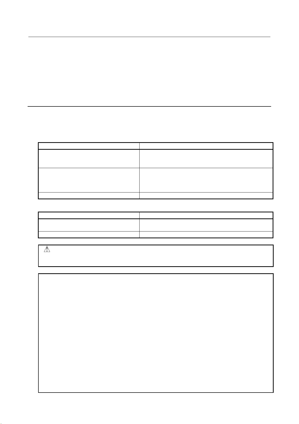
3.2.1 Selection of Network Interface Board
1 Start “SIMATIC NCM PC Manager” from start menu, for example.
2 Click “Set PG/PC Interface” of “Option” tool bar.
3 Wait for a while, and the window like below appears.
4 Select network interface board that is used for PROFINET connection among the items whose name
start by TCP/IP or TCP/IP(Auto).
- 11 -
Page 22

3. SETUP PROFINET I/O B-82864EN/09
3.2.2 Setting IP Address and Device Name
1 Start “SIMATIC NCM PC Manager” from start menu, for example.
2 Click “Edit Ethernet Node” from “PLC” tool bar.
The window like below appears after a while.
3 Press “Browse” button. The configuration tool will search all devices connected to the Ethernet. The
window like below appears after a while.
4 Find out PROFINET board and select it. Then press “OK”.
5 The window like below appears. IP address and device name can be set from this window.
6 Enter IP address and subnet mask. Press “Assign IP Configuration”.
- 12 -
Page 23

B-82864EN/09 3. SETUP PROFINET I/O
NOTE
to initialize PROFINET board.
7 Enter device name and press “Assign Name” button.
Device name cannot be modified if PROFINET board has been configured as I/O
Controller. In this case, press “Reset” button in the “Reset to factory setting” field
8 This procedure is completed. Press “Close” button to close the window.
3.3 MAKING PROFINET PROJECT BY CONFIGURATION
TOOL
This section describes the outline of how to set up PROFINET I/O Controller by using NCM PC
configuration tool. Please refer to the start up of the operation manual of NCM PC or STEP7 for the details.
3.3.1 SIMATIC NCM PC Manager
First of all, start “SIMATIC NCM PC Manager” to create new project. After a project is created, the window
like below shows up. Right click the window and select “Insert New Object”. Add “SIMATIC PC Station”
and “Industrial Ethernet”.
- 13 -
Page 24

3. SETUP PROFINET I/O B-82864EN/09
The left window displays the hierarchy of the project. “SIMATIC PC Station” has been added. The right
window displays the components of the selected level of the hierarchy. Clicking a component will open
other configuration software such as “NetPro” or “SIMATIC NCM PC Config” for detailed configuration
of the component.
Example 1)
Select the top level in the left window. Double click “Industrial Ethernet”, and NetPro will open.
Example 2)
Select “SIMATIC PC Station”. Double click “Configuration”, and “SIMATIC NCM PC Config” will
open.
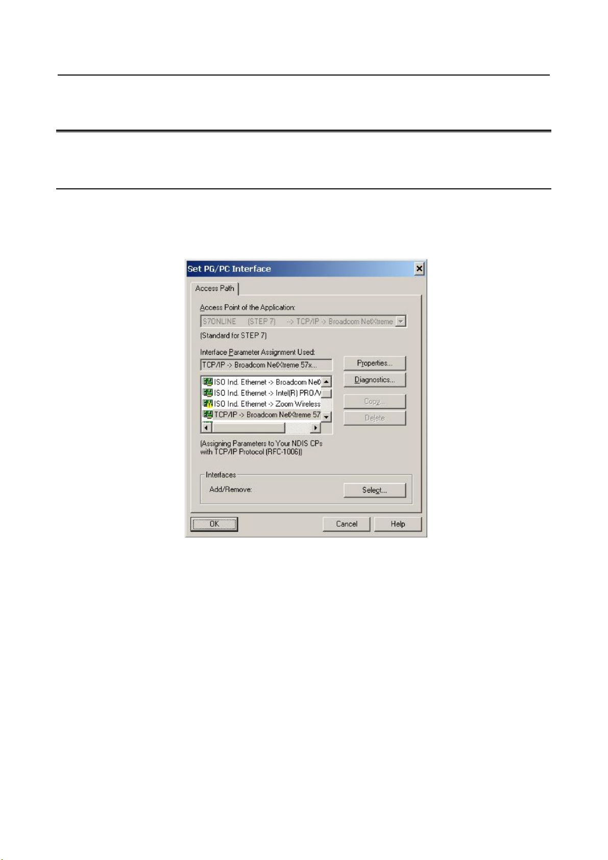
3.3.2 SIMATIC NCM PC Config
“SIMATIC NCM PC Config” is used for setting up the configuration of PROFINET module. PROFINET
board must be added to “SIMATIC PC Station” by this software.
This section explains the procedure of setup by using CP1616 V2.0 as an example. However, the version
should be chosen according to the firmware version of PROFINET board when actual configuration is to
be made.
1 Starts “SIMATIC NCM PC Config” “ or “HW Config” according to the example 2 of 3.3.1.
2 Select the top of empty row of PC.
3 Click “CP Industrial Ethernet” in the right window to show the lower level.
4 Select V2.0 under “CP1616”, and the top row of PC becomes green, which means the selected
component can be inserted here.
- 14 -
Page 25
B-82864EN/09 3. SETUP PROFINET I/O
5 Double click V2.0, and the windows like below shows up.
6 Check IP address and subnet mask are correct.
7 Select the network to connect CP1616in the “Subnet” field.
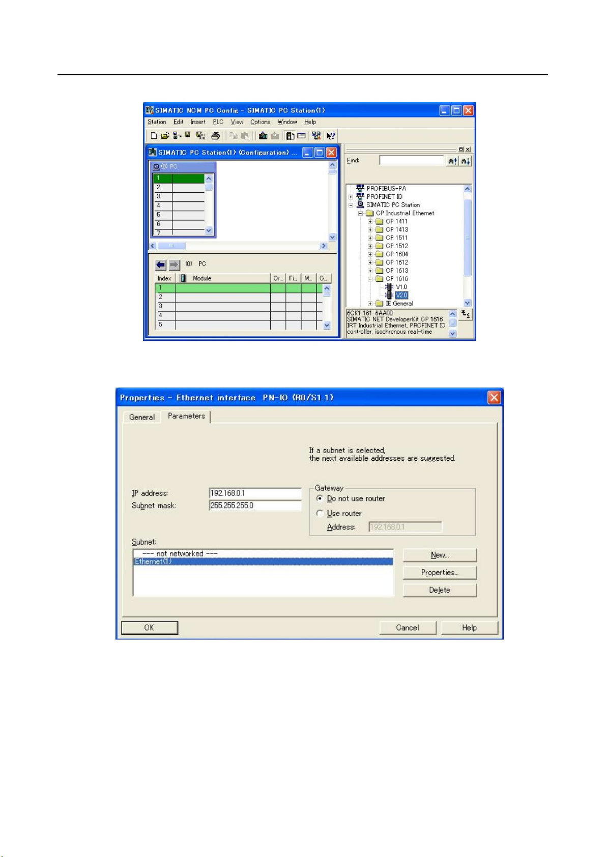
8 Press “OK” to close the window, and an Ethernet cable shows up inside the left window.
CP1616 has been connected to the Ethernet.
9 After modification finishes, do “Save and Compile” to apply the changes.
By the similar procedure, it is possible to add the device here that communicates with CP1616. Click the
Ethernet cable that shows up in step 8, and click “IM151-3 PN” under “PROFINET I/O->I/O->ET200S”,
for example. Then “IM151-3 PN” module is added like the figure below. Then add the input/output modules
to the remaining rows of “IM151-3 PN”.
- 15 -
Page 26
3. SETUP PROFINET I/O B-82864EN/09
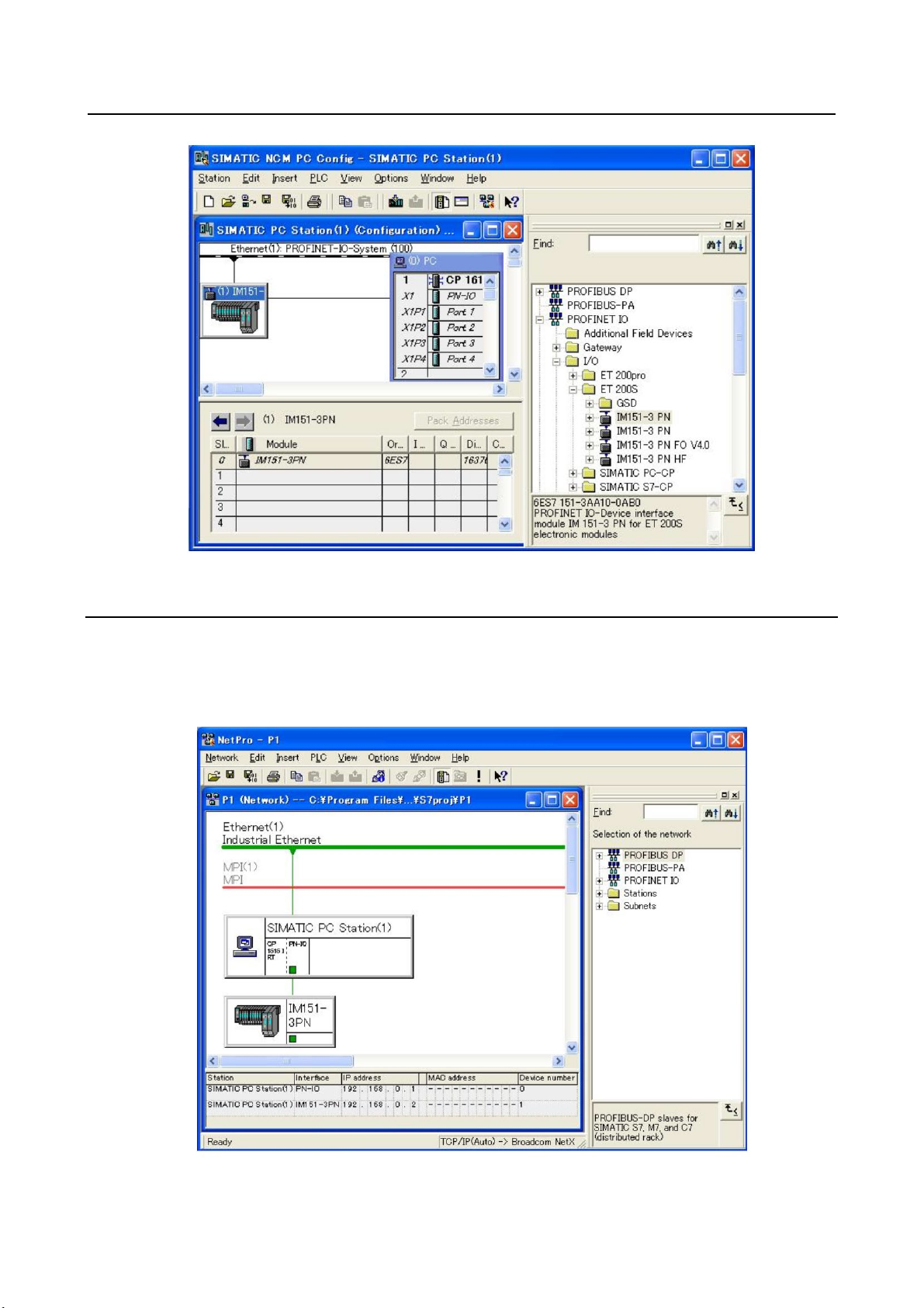
3.3.3 NetPro
NetPro can setup the configuration of PROFINET network. “NetPro” can be opened according to the
example 1 of Subsection 3.3.1. The figure below shows the network after adding “IM151-3 PN module
according to Subsection 3.3.2.
- 16 -
Page 27

B-82864EN/09 3. SETUP PROFINET I/O
General
1/4
1. MAX_DIG_PRT :
2048
2. Start up mode :
[SUSPEND]
3. I/O Controller
ENABLED
4. I/O Device
ENABLED
[ TYPE ] [Other] >
CLR_ASG
Setup PROFINET IO JOINT 10 %
WARNING
6.2 for more detail.
NOTE
setting, and is displayed in setup I/O Device screen (refer to 3.4.3).
3.4 SETUP SCREENS
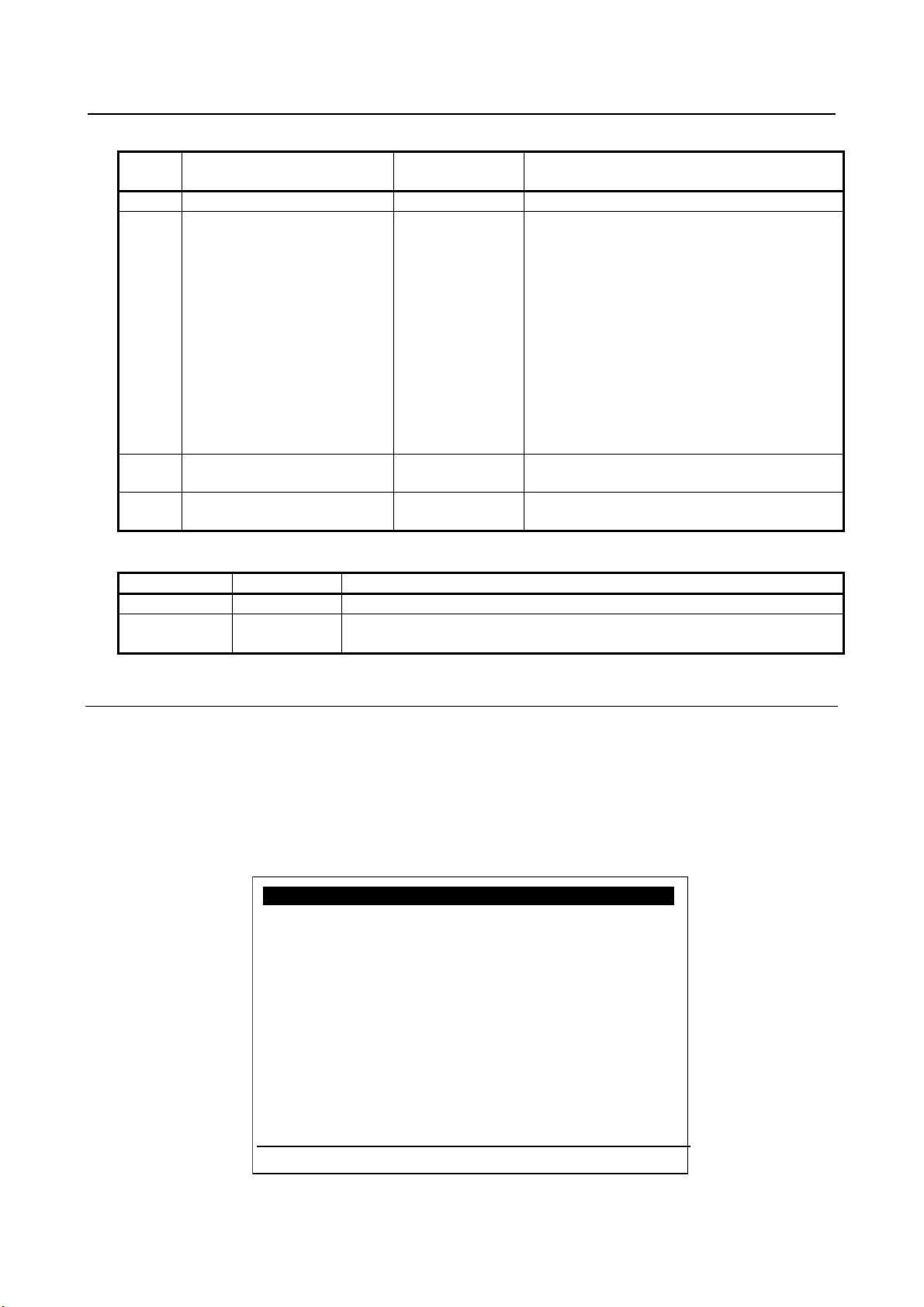
3.4.1 Setup General Screen
Use this screen to select start up mode, and to change Enable/Disable of I/O Controller and I/O Device.
Press F3 key to show up the pop-up menu to open other screens. Press F10 key (press NEXT and then press
F5) to clear I/O assignment.
Fig. 3.4.1 (a) Setup general screen
1 Changing start up mode from SUSPEND immediately takes effect, that is,
PROFINET function of the robot controller starts immediately. Please verify the
safety is assured and make sure if it is safe to start PROFINET I/O data
exchange before changing the start up mode from SUSPEND.
2 Cycle power the robot controller after changing start up mode to READ IN if the
robot software version is 7DA5/01-22(V7.50P/01-22), 7DB6/01-08(V7.63P/01-
08), 7DA7/01-29(V7.70P/01-29) or 7DC1/01-06(V8.10P/01-06). Please refer to
1 The comment of modules is erased when the network configuration is read in.
To recover the comment, please write it down before changing start up mode to
READ IN.
2 I/O Controller has initial setting of input/output size for DIO and AIO. If I/O
Controller is not used, set 0 to “Number of digital input/output” for DIO and
“Number of analog input/output” for AIO in setup I/O Controller screen (refer to
3.4.2). Find the assignment with rack 99, slot 1 in digital I/O config screen and
analog I/O config screen under I/O menu and delete them. Cycle power the
robot controller to apply the change.
3 I/O Device doesn’t have any initial setting. I/O Device setting must be made by
Module list/detail screens (refer to 3.4.3.1 and 3.4.3.2). The input/output size for
DIO and AIO is calculated from the process data size of modules in I/O Device
- 17 -
Page 28
3. SETUP PROFINET I/O B-82864EN/09
#
Item
Adjustable
values
Description
1
MAX_DIG_PRT
-
This item displays $MAX_DIG_PRT
communication does not start.
3 (a)
I/O Controller
ENABLE
DISABLE
Enable/Disable of I/O Controller
DISABLE
Function key
Words
Description of function keys
F3
Other
Selection of setup screens
Clear ALL I/O assignments?
I/O Controller
1/5
1. Error one shot : DISABLED
2. Number of digital input :
1024
3. Number of digital output : 1024
4. Number of analog input : 25
5. Number of analog output : 25
6. Digital input offset address: 0
7. Digital output offset address: 0
8. Analog input offset address: 512
9. Analog output offset address: 512
[ TYPE ] [Other] arc analog >
CLR_ASG
Setup PROFINET IO JOINT 10 %
Table 3.4.1 (a) Setup general screen items
2 (a) Start up mode SUSPEND
READ IN
OPERATION
4 (a) I/O Device ENABLE
(a) Need to cycle power to have the change applied.
F10 CLR_ASG Clear I/O assignments
SUSPEND: (setup stage)
To start up with the PROFINET board stopped.
The project can only be downloaded in this state.
READ IN: (setup stage)
PROFINET board starts automatically and
network configuration of I/O Controller is read in
from PROFINET board.
OPERATION: (production stage)
PROFINET board starts automatically and
network configuration of I/O Controller is
checked if it is matched to the stored one. If it
does not match, error message shows up and
Enable/Disable of I/O Device
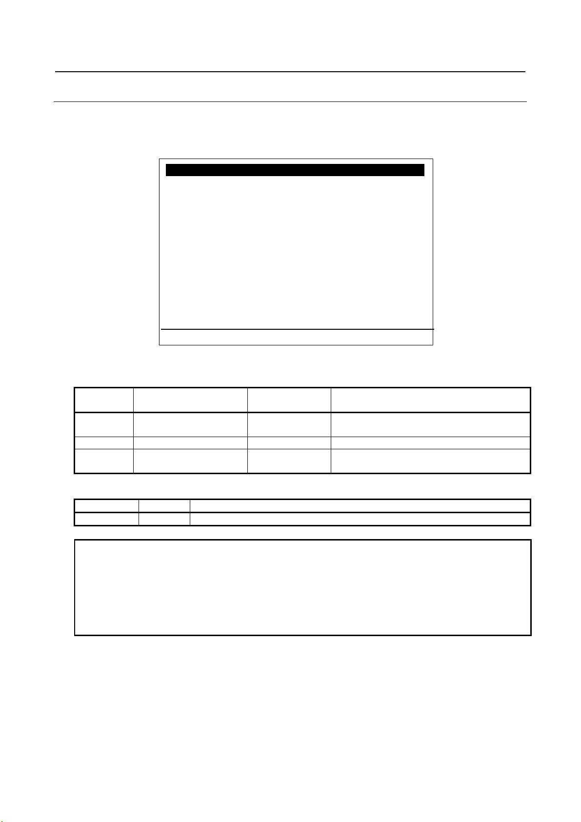
3.4.2 Setup I/O Controller Screen
The items 2-5 specify the size of digital I/O and analog I/O of PROFINET. Items 6-9 specify the start
address of PROFINET data that are mapped to digital I/O or analog I/O. This address can be assigned to
each I/O Device in the PC configuration tool. The areas specified by the size and the start addresses are
mapped to digital I/O or analog I/O. The data for I/O Devices that you want to use for analog I/O is allocated
from the address of analog I/O set here to the data size area of analog I/O points.
Press F3 key to show up the pop-up menu to open other screens. Press F4 key to open arc welding I/O
screen. Press F5 key to open analog I/O list screen. Press F10 key to clear I/O assignment.
Fig.3.4.2 (a) Setup I/O controller screen
- 18 -
Page 29

B-82864EN/09 3. SETUP PROFINET I/O
#
Item
Adjustable
values
Description
1
Error one shot
ENABLE
If it is ENABLE, pressing reset button can erase
present.
The value must be multiple of 8.
3 (a)
Number of digital output
0-2048
Numbers of DO mapped as rack 99.
The value must be multiple of 8.
4 (a)
Number of analog input
0-25
Number of AI mapped as rack 99.
5 (a)
Number of analog output
0-25
Number of AO mapped as rack 99.
DI (rack 99).
7(a)
Digital output offset address
0-9998
The start address of PROFINET data mapped to
DO (rack 99).
AI (rack 99).
9(a)
Analog output offset address
0-9998
The start address of PROFINET data mapped to
AO (rack 99).
Function key
Words
Description of function keys
F3
Other
Selection of setup screens
F4
arc
Arc welding signal screen
F5
analog
Analog list screen
Clear ALL I/O assignments?
NOTE
allocated.
Table 3.4.2 (a) Setup I/O controller screen items
DISABLE
2 (a) Number of digital input 0-2048 Number of DI mapped as rack 99.
6(a) Digital input offset address 0-9998 The start address of PROFINET data mapped to
8(a) Analog input offset address 0-9998 The start address of PROFINET data mapped to
network error of I/O Controller even if it is
(a) Power OFF/ON is necessary to enable a change of settings.
F10 CLR_ASG Clear I/O assignments
The data of a PROFINET I/O module can be allocated to only a single type of I/O
(digital, analog, arc welding). It must be placed within the area specified by the
start address and the size for a type of I/O and it must not be placed across the
border of any areas, otherwise it is not allocated to any I/O. In such case, PRIO630 appears at start up with PRIO-631 or PRIO-632 to inform which data is not
- 19 -
Page 30
3. SETUP PROFINET I/O B-82864EN/09
I/O Controller : Arc weld I/O 1/25
1. Enable arc weld I/O : False
2. WI offset :
0
3. WI size :
0
4. WO offset :
0
5. WO size :
0
6. WSTK(IN) offset : 0
7. WSTK(IN) size :
0
8. WSTK(OUT) offset : 0
9. WSTK(OUT) size : 0
[ TYPE ] [Other]
Setup PROFINET IO JOINT 10 %
values
True
be “True” only if arc tool is ordered.
2,4,6,8 (a)
WI/WO/WSTK offset
0-9998
Address where WI/WO/WSTK starts.
The value must be multiple of 8.
Function key
Words
Description of function keys
F3
Other
Selection of setup screens
NOTE
allocated.
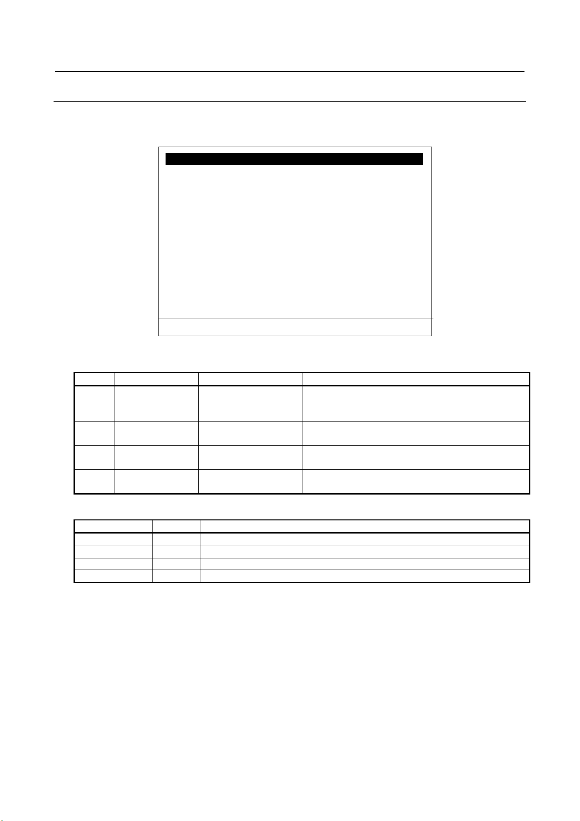
3.4.2.1 Arc welding signal screen
The setting of arc welding signals, such as WI/WO or WSTK, that are used by Arc tool can be modified in
this screen. This screen can be used only when the application is Arc tool. Press PREV to go back to I/O
Controller screen.
Fig. 3.4.2.1 (a) Arc welding signal screen
Table 3.4.2.1 (a) Arc welding signal screen items
# Item Adjustable
1 (a) Enable arc weld I/O False
3,5,7,9 (a) WI/WO/WSTK size 0-40 Number of WI/WO/WSTK mapped as rack 99.
Specify if WI/WO and WSTK are available. It can
Description
(a) Power OFF/ON is necessary to enable a change of settings.
The data of a PROFINET I/O module can be allocated to only a single type of I/O
(digital, analog, arc welding). It must be placed within the area specified by the
start address and the size for a type of I/O and it must not be placed across the
border of any areas, otherwise it is not allocated to any I/O. In such case, PRIO630 appears at start up with PRIO-631 or PRIO-632 to inform which data is not
- 20 -
Page 31

B-82864EN/09 3. SETUP PROFINET I/O
I/O Controller : List AO 1/25
NO Addr Comment
AO[ 1] 512 [ ]
AO[ 2] 514 [ ]
AO[ 3] 516 [ ]
AO[ 4] 518 [ ]
AO[ 5] 520 [ ]
AO[ 6] 522 [ ]
AO[ 7] 524 [ ]
AO[ 8] 526 [ ]
AO[ 9] 528 [ ]
[ TYPE ] detail [Other] I/O
Setup PROFINET IO JOINT 10 %
#
Item
Adjustable values
Description
1
No
None
Analog output number
located (Address must be equal to NCM or STEP7).
3
Comment
None
String[24]
Comment of this analog output (the same as AI/AO screen).
Display only.
Function key
Words
Description of function keys
F2
detail
Go to detail screen
F3
Other
Selection of setup screens
F5
I/O
Switch AO and AI.
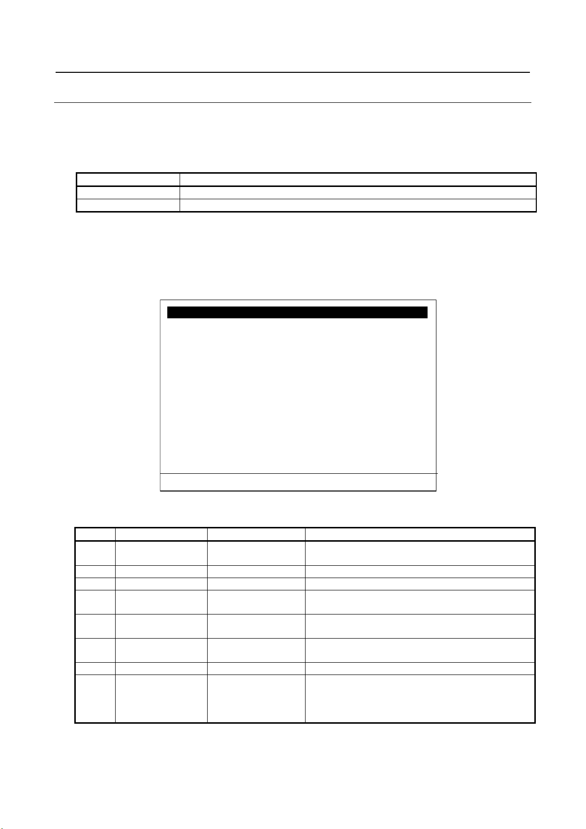
3.4.2.2 Analog list screen
There are analog list screens for AO and AI. These screens show the mapping of analog I/O of the robot
controller and the address of PROFINET data. The comment of analog I/O is also displayed in this screen.
Press PREV to go back to I/O Controller screen. Press F2 key to open analog detail screen. Press F5 key to
switch AO and AI.
Fig. 3.4.2.2 (a) Analog list screen (AO)
Table 3.4.2.2 (a) Analog list screen items
2 Addr None Address in bytes, where the PROFINET data for this AI/AO is
Power OFF/ON is necessary to enable a change of settings.
- 21 -
Page 32
3. SETUP PROFINET I/O B-82864EN/09
I/O Controller : Detail AO 1 1/2
Address : 512
Comment :
[ ]
1. AO left shift count : 0
2. AO valid bits : 16
[ TYPE ]
list prev next I/O
Setup PROFINET IO JOINT 10 %
#
Item
Adjustable values
Description
Display only
String[24]
screen). Display only.
AO left shift count
1-16
value.
1-16
valid bits are treated as 0.
Function key
Words
Description of function keys
F2
list
Go to list screen
F3
prev
Go to previous analog port
F4
next
Go to next analog port
F5
I/O
Switch AO and AI.
3.4.2.3 Analog detail screen
There are analog detail screens for AO and AI. The setting of bit shift operation and valid bits can be
modified in this screen. Use default setting if the value of analog signal is to be used as original value.
Fig. 3.4.2.3 (a) Analog detail screen(AO)
Table 3.4.2.3 (a) Analog detail screen items
Address Address in bytes, where the value for this AI/AO is
located (Address must be equal to NCM or STEP7).
Comment None
1 (a) AI right shift count
2 (a) AI/AO valid bits 16
0
Comment of this analog output (the same as AI/AO
This is the setting for how many bits right or left shift the
Set the number of valid bits. Bits not included in the
(a) Power OFF/ON is necessary to enable a change of settings.
- 22 -
Page 33

B-82864EN/09 3. SETUP PROFINET I/O
I/O Device 1/2
1. Error one shot : DISABLED
2. Modules
<Detail>
3. Number of digital inputs :
128
4. Number of digital outputs : 128
5. Number of analog inputs : 0
6. Number of analog outputs : 0
[ TYPE ] [Other] >
CLR_ASG
Setup PROFINET IO JOINT 10 %
#
Item
Adjustable values
Description
Use this only during setup.
2
Modules
None
Moves to “Module list” sub screen by pressing
enter key with the cursor on this item.
according to setting. Not actual value.
4
Number of digital outputs
None
Displays sum of digital output number of modules,
according to setting. Not actual value.
according to setting.
6
Number of analog outputs
None
Displays sum of analog output number of modules,
according to setting.
Function key
Words
Description of function keys
F3
Other
Selection of setup screens
NOTE
Device screen and Module list/detail screens when I/O Controller is disabled.
3.4.3 Setup I/O Device Screen
This screen is a top screen for I/O Device setting. The robot controller as PROFINET I/O Device is a
modular device, that is, it is composed of up to 17 modules. The configuration of modules is made in the
module list/detail screens. To enter module list screen, move cursor to the second line, “Module”, and press
Enter. This screen shows the amount of digital and analog I/O used by the robot controller as PROFINET
I/O Device.
Fig. 3.4.3 (a) Setup I/O Device screen
Table 3.4.3 (a) Setup I/O Device items
1 Error one shot ENABLE
DISABLE
3 Number of digital inputs None Displays sum of digital input number of modules,
5 Number of analog inputs None Displays sum of analog input number of modules,
If it is ENABLE, pressing reset button can erase
network error of I/O Controller even if it is present.
which are to be mapped to rack 100. Calculated
which are to be mapped to rack 100. Calculated
which are to be mapped to rack 100. Calculated
which are to be mapped to rack 100. Calculated
Power OFF/ON is necessary to enable a change of settings.
Appendix B provides an example of I/O Device setting and usage of Setup I/O
- 23 -
Page 34

3. SETUP PROFINET I/O B-82864EN/09
I/O Device : Modules
1/17
No Slot Sub Comment
0 0 1 [CP1616 V2.
5 ]
1 1 1 [
]
2 2 1 [
]
3 0 0 [
]
4 0 0 [
]
5 0 0 [
]
6 0 0 [
]
7 0 0 [ ]
8 0 0 [ ]
9 0 0 [ ]
[ TYPE ] detail [Other] >
DEL_ALL
Setup PROFINET IO JOINT 10 %
#
Item
Adjustable
values
Description
1
Slot
None
0-16
Displays slot number
Slot number is up to 16.
0-1
3
Comment
String[24]
Explanation of the module
Function key
Words
Description of function keys
F2
detail
Go to Module Detail screen of the selected submodule.
F3
Other
Selection of setup screens.
Delete ALL modules?
NOTE
both of I/O Controller and I/O Device are enabled in the robot controller.
3.4.3.1 Module list screen
The robot controller as PROFINET I/O Device is composed of up to 17 modules. There is no module
defined by default, therefore modules location (slot, subslot) and module identifier (modId, subslotId) must
be specified by module list/detail screens. There is a device access point (always slot 0 before 7DC3(V8.30),
slot 1 in 7DC3(V8.30)), input modules, output modules, and input/output modules. Please refer to the
GSDML file for the parameters of modules. Select a submodule and press F2 Detail to enter the parameters
of the submodule. Press PREV to go back to setup I/O Device screen.
Fig. 3.4.3.1 (a) Module list screen
Table 3.4.3.1 (a) Module list screen
2 Sub None
Displays sub slot number
Power OFF/ON is necessary to enable a change of settings.
F7 DEL_ALL Delete all module settings.
1 Appendix B provides an example of I/O Device setting and usage of Setup I/O
Device screen and Module list/detail screens when I/O Controller is disabled.
2 The first module must be device access point. Choose the device access point
without “Migration” subcategory when only I/O Device is enabled in the robot
controller. Choose the device access point with “Migration” subcategory when
- 24 -
Page 35
B-82864EN/09 3. SETUP PROFINET I/O
Item name
Property name in GSDML file (use PROFINET-XML viewer to open the file)
ModId
Module Ident Number
SubslotId
Submodule Ident Number
I/O Device : Module 1
1/6
1. Slot : 1
2. Subslot : 1
Comment :
3. [ ]
4. ModId(hex) : 0x00000027
5. SubslotId(hex) : 0x00000001
Module I/O type : DO
6. Data size : [16 Bytes]
7. Data type : [Digital]
[ TYPE ] list prev next
Setup PROFINET IO JOINT 10 %
#
Item
Adjustable values
Description
Slot number is up to 16.
2(a)
Sub
0-1
Sub slot number of the module
3
Comment
String[24]
Explanation of the module
4(a)
ModId
LONG
Module Id of the module
Enter the value by decimal number.
Enter the value by decimal number.
Module I/O type
DI, DO, AI, AO,
NONE
The type of I/O of the module decided by the direction of
data and the data type (item 7).
6(a)
Data size
0, 1, 4, 16 Bytes (b)
Choose from 0, 1, 4, and 16 Bytes (b)
7(a)
Data type
Digital
Choose from digital and analog.
doesn’t have any effect on PROFINET I/O exchange.
3.4.3.2 Module Detail Screen
Enter the parameters of the module that consists of the robot controller as PROFINET I/O Device in this
screen. Slot and subslot specify the location of the module within 17 slots. ModId and subslotId specify the
type of module. Please see the following properties in the GSDML file for ModId and SubslotId.
Table 3.4.3.2 (a) ModId and SubslotId
When module ID is entered, internal database is searched to find out the module. If there is a match, data
size and module I/O type are automatically set. Enter slot, subslot and subslotId by manual. Choose data
type from digital and analog.
The parameters of module (except for data type) must be equal to those of project made by configuration
tool. Otherwise, error will occur and the communication will not establish.
Fig. 3.4.3.2 (a) Module detail screen
Table 3.4.3.2 (b) Module detail screen
1(a) Slot 0-16 Slot number of the module
5(a) SubslotId LONG Subslot Id of the module
(a) Power OFF/ON is necessary to enable a change of settings.
(b) For 7DA5/14(V7.50P/14) or later, 7DA7/22(V7.70P/22) or later, R-30iB, please see the GSDML file
for robot by FANUC.
Analog
It specifies if the process data is assigned to DI/DO or
AI/AO. 1Byte module can’t be assigned to analog. It
- 25 -
Page 36

3. SETUP PROFINET I/O B-82864EN/09
Function key
Words
Description of function keys
F2
list
Go to module list screen
F3
prev
Go to previous module
F4
next
Go to next module
NOTE
I/O Device screen and Module list/detail screens when I/O Controller is disabled.
I/O Controller : Config list 1/256
St Slot Sub Comment
E 1 2 1 [ ]
E 1 5 1 [ ]
E 1 6 1 [ ]
E 1 8 1 [ ]
E 2 2 1 [ ]
E 2 3 1 [ ]
E 2 4 1 [ ]
E 2 6 1 [ ]
D 0 0 0 [ ]
D 0 0 0 [ ]
[ TYPE ] detail [Other]
Setup PROFINET IO
JOINT 10 %
values
Press F5 Disable to disable the module.
0-999
3
Slot
None
0-999
Displays slot number
0-999
5
Comment
String[24]
Explanation of the module
Function key
Words
Description of function keys
F2
detail
Go to config detail screen
F3
Other
Selection of setup screens
Appendix B provides an example of I/O Device setting and usage of Setup
3.4.4 Setup Configuration List Screen
This screen displays the configuration of I/O Controller that has been read in when the start up mode is
READ IN. After the configuration is read in, device can be activated or deactivated by changing the item
of E/D when TP is enabled. The comment of device can be entered in this screen. If the comment is set to
the first device of a station, the comment will be shown next to the TP switching instruction when the
instruction is taught in a TP program. Some error message displays the comment as well as error location.
Fig. 3.4.4 (a) Setup Configuration list screen
Table 3.4.4 (a) Setup Configuration list screen
# Item Adjustable
1 E/D Enable
Disable
2 St None
4 Sub None
Power OFF/ON is necessary to enable a change of settings.
- 26 -
Module can be activated/deactivated from here.
Press F4 Enable to enable the module.
Displays station number
Displays sub slot number
Description
Page 37
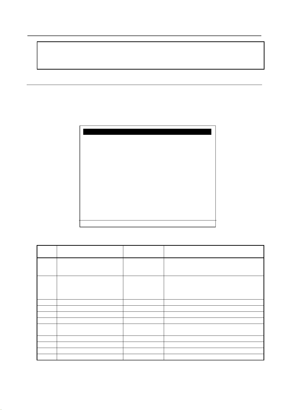
B-82864EN/09 3. SETUP PROFINET I/O
NOTE
READ IN.
I/O Controller : Module 1
1/11
1. Status : Enable
2. Show error when deactivated:On
3. Station : 1
4. Slot :
2
5. Subslot :
1
Comment :
6. [ ]
7. Address : 0
8. Length : 1
9. IO data type : IN
10. Data type : 0
11. Com type : 0
[ TYPE ] list prev next
Setup PROFINET IO JOINT 10 %
values
Press F5 Disable to disable the module.
instruction.
3
Station
LONG
Station number of the module
4
Slot
LONG
Slot number of the module
5
Sub
LONG
Sub slot number of the module
6
Comment
String[24]
Explanation of the module
configuration tool (NCM or STEP7).
8
Length
LONG
Process data length of the module
9
I/O data type
Shows data type is input or output
10
Data type
11
Com type
The comment of modules is erased when the network configuration is read in.
To recover the comment, please write it down before changing start up mode to
3.4.4.1 Configuration detail screen
This screen shows the detail of the module within the configuration of I/O Controller that has been read in
when the start up mode is READ IN. After the configuration is read in, device can be activated or
deactivated by changing the status to enable or disable when TP is enabled. The comment of device can be
entered in this screen.
To show error message when the device is deactivated, set the second item to ON.
Fig. 3.4.4.1 (a) Configuration detail screen
Table 3.4.4.1 (a) Configuration detail screen
# Item Adjustable
1 Status Enable
2 Show error when deactivated Off
7 Address LONG Process data address of the module specified by
Power OFF/ON is necessary to enable a change of settings.
Disable
On
Description
Module can be activated/deactivated from here.
Press F4 Enable to enable the module.
When the setting is On, error message will show
up when the device is disconnected unless it is
deactivated by configuration screen or TP
- 27 -
Page 38

3. SETUP PROFINET I/O B-82864EN/09
Function key
Words
Description of function keys
F2
list
Go to config list screen
F3
prev
Go to previous module
F4
next
Go to next module
NOTE
READ IN.
WARNING
exchange before changing the start up mode from SUSPEND.
NOTE
connect it again after power up.
The comment of modules is erased when the network configuration is read in.
To recover the comment, please write it down before changing start up mode to
3.5 DOWNLOAD OF PROJECT IN SUSPEND MODE
It is required to download a project to PROFINET board by configuration tool. If there is any other
PROFINET I/O Controller in the network, the project must be downloaded to the stations, too.
Change start up mode to “READ IN” when download is completed.
Changing start up mode from SUSPEND immediately takes effect, that is,
PROFINET function of the robot controller starts immediately. Please verify the
safety is assured and make sure if it is safe to start PROFINET I/O data
1 When the robot controller starts up with start up mode other than SUSPEND,
project cannot be downloaded to PROFINET board.
2 When the robot controller starts up with SUSPEND start up mode, PROFINET
board is stopped. Start up mode must be SUSPEND when firmware of
PROFINET board is updated.
3 Cycle power the robot controller after firmware update. If the external power
supply of PROFINET board is connected, remove it before cycle power and
3.6 READ IN MODE
The robot controller tries to establish PROFINET communication when start up mode is changed from
“SUSPEND” mode to “READ IN” mode or when it starts up with “READ IN” mode. If there is wrong
setting or the configuration does not match to the downloaded project, error will occur.
If there is no error, current configuration will be read in to the robot controller and PROFINET
communication will establish, but PRIO-623 with STOP severity will be posted to prohibit robot motion.
To release PRIO-623, change start up mode to OPERATION and cycle power the robot controller.
The configuration read in will be stored and used when start up mode is OPERATION. On the other hand,
if the robot controller starts up with “READ IN” mode, configuration will be read in and last configuration
will be overwritten. The setting in Subsection 3.4.4 and 3.4.4.1 are initialized.
- 28 -
Page 39

B-82864EN/09 3. SETUP PROFINET I/O
WARNING
before changing start up mode to OPERATION.
NOTE
READ IN.
1 Cycle power the robot controller after changing start up mode to READ IN if the
robot software version is 7DA5/01-22(V7.50P/01-22), 7DB6/01-08(V7.63P/01-
08), 7DA7/01-29(V7.70P/01-29) or 7DC1/01-06(V8.10P/01-06). Please refer to
6.2 for more detail.
2 Please confirm if the communication is OK and I/O data is exchanged correctly
The comment of modules is erased when the network configuration is read in.
To recover the comment, please write it down before changing start up mode to
3.7 OPERATION MODE
The robot controller starts up with the stored configuration, and check if it matches to the current
configuration. Therefore, use OPERATION mode after PROFINET setting is completed.
The setting of “Show error when deactivated” (see 3.4.4.1) will be used in OPERATION mode. If the
device with the setting = ON is disconnected, error message will show up unless the device is deactivated
by configuration screen or TP instruction. The device switching status is recovered at power failure
recovery in OPERATION mode.
- 29 -
Page 40

4. STATUS SCREEN B-82864EN/09
I/O Controller : Module list
1/256
St Slot Sub Addr Len RS_I RS_O
E 1 2 1 0 1
0000 0000
E 1 5 1 2 1
0000 0000
E 1 6 1 0 1
0000 0000
E 1 8 1 2 1
0000 0000
E 2 2 1
4 1 0000 0000
E 2 3 1 6 1
0000 0000
E 2 4 1 4 1 0000 0000
E 2 6 1 6 1 0000 0000
D 0 0 0 0 0 0000 0000
D 0 0 0 0 0 0000 0000
[ TYPE ] detail
Status PROFINET IO JOINT 10 %
#
Item
Values
Description
DISABLE
0-999
0-999
0-999
5
Address
None
0-99999
Displays process data address
0-999
7
RS_I
Remote status of Input data
8
RS_O
Remote status of Output data
Function key
Words
Description of function keys
F2
detail
Go to module detail screen
4 STATUS SCREEN
4.1 I/O CONTROLLER MODULE LIST SCREEN
This screen shows the list of modules of I/O Device that communicate with the robot controller. The list is
based on current PROFINET configuration, and therefore it can be different with the list of setup
configuration list screen when start up mode is OPERATION.
1 E/D ENABLE
2 Station None
3 Slot None
4 Sub None
6 Length None
Fig. 4.1 (a) Status module list screen
Table 4.1 (a) Status module list screen
Shows if the module is activated or not.
Displays station number
Displays slot number
Displays sub slot number
Displays process data length
- 30 -
Page 41
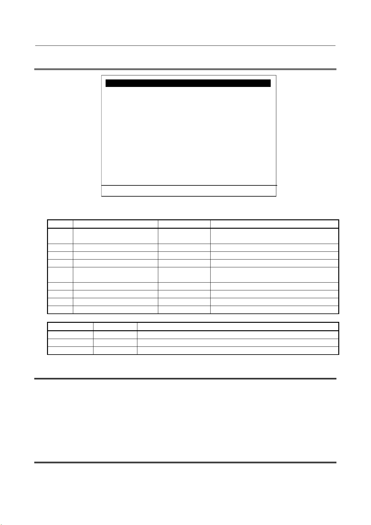
B-82864EN/09 4. STATUS SCREEN
I/O Controller : Module 1
1/11
1. Status :
Enable
2. Station :
1
3. Slot :
2
4. Subslot :
1
5. Address :
0
6. Length : 0
7. IO data type : 0
8. Data type :
0
9. Com type :
0
[ TYPE ] list prev next
Status PROFINET IO JOINT 10 %
#
Item
Values
Description
Disable
2
Station
LONG
Station number of the module
3
Slot
LONG
Slot number of the module
4
Sub
LONG
Sub slot number of the module
configuration tool (NCM or STEP7).
6
Length
LONG
Process data length of the module
7
I/O data type
Shows data type is input or output
8
Data type
9
Com type
Function key
Words
Description of function keys
F2
list
Go to module list screen
F3
prev
Go to previous module
F4
next
Go to next module
4.2 I/O CONTROLLER MODULE DETAIL SCREEN
Fig. 4.2 (a) Status module detail screen
Table 4.2 (a) Status module detail screen
1 Status Enable
5 Address LONG Process data address of the module specified by
Shows if the module is activated or not.
4.3 PROFINET SAFETY DETAIL SCREEN
To open PROFINET Safety detail screen, please go to MENUS -> SYSTEM -> Type / F1 -> DCS, move
cursor on “PROFINET Safety” and press the DETAIL / F3.
Please refer to “R-30iA/R-30iA Mate CONTROLLER Dual Check Safety Function (ISO 13849-1:2006
compliant) OPERATOR’S MANUAL (B-83104EN)” or “R-30iB/R-30iB Mate/R-30iB Plus/R-30iB Mate
Plus/R-30iB Compact Plus CONTROLLER Dual Check Safety Function OPERATOR’S MANUAL (B83184EN)” in addition to this manual for details.
4.4 PROFINET BOARD FIRMWARE SCREEN
You can update and check PROFINET board firmware in this screen. Please refer to Fig. A.4 (a) in
Appendix A.4 for details.
- 31 -
Page 42

5. DEVICE SWITCHING TP INSTRUCTION B-82864EN/09
TEST LINE 0 ABORTED
1 : PNIO attach 3 “Module Comment”
2 :
3 : PNIO detach 3 “Module Comment”
[ INST ] [EDCMD]
TEST JOINT 10 %
Instruction
argument
Description
PNIO attach
station no.
Activate the specified module and wait until it is activated, or timeout
from config list/detail screen and displayed after module no.
brought from config list/detail screen and displayed after module no.
5 DEVICE SWITCHING TP INSTRUCTION
Device switching TP instruction is used to activate or deactivate PROFINET I/O Device, such as a
peripheral I/O module on detachable hand or tool. Specify the operation (attach or detach) and the station
number in the instruction. The device switching status is recovered at power failure recovery in
OPERATION mode.
Fig. 5 (a) TP instruction to activate and deactivate module
Table 5 (a) TP instruction to activate and deactivate module
occurs. Module comment of the first module of the station is brought
PNIO detach station no. Deactivate the specified module and wait until it is deactivated or
timeout occurs. Module comment of the first module of the station is
- 32 -
Page 43

B-82864EN/09 6. TROUBLESHOOTING
NOTE
READ IN.
6 TROUBLESHOOTING
6.1 ERROR CODES
Please refer to Appendix H for the list of error codes.
6.2 INFORMATION ABOUT I/O CONTROLLER
When I/O Controller function is used, READ IN is done to read in the network configuration after
downloading the project to PROFINET board firmware. Then the order of modules in network
configuration read in by the first READ IN and those of the following READ IN may differ.
If the robot software version is 7DA5/01-22(V7.50P/01-22), 7DB6/01-08(V7.63P/01-08), 7DA7/0129(V7.70P/01-29) or 7DC1/01-06(V8.10P/01-06), the robot software is affected by this, therefore it is
required to cycle power the robot controller after the first READ IN to do the second READ IN at next
power on.
If the start up mode is changed to OPERATION after the first READ IN (without the required cycle power),
the following problem may occur.
1. The enable/disable status of device is not recovered correctly at power failure recovery.
The station disabled before power off gets to enable, and another station gets to disable.
2. The comment of module where alarm indication comes from is not displayed correctly.
The comment of other module may be displayed.
The same problem may occur when PROFINET board is changed, or PNIO.SV is restored.
To know if the condition of the problem occur is true or not, compare the order of modules in the setup
configuration list screen (refer to 3.4.4) with that in the status module list screen (refer to 4.1). If they don’t
match, the problem may occur. As a workaround of the problem, please follow the procedure below to do
READ IN again.
Procedure 6.2 : Retry of READ IN
1 Write down the comment of modules in the setup configuration list screen.
The comment of modules is erased when the network configuration is read in.
To recover the comment, please write it down before changing start up mode to
2 Change the start up mode to READ IN in the setup general screen, and then cycle power the robot
controller.
3 Change the start up mode to OPERATION in the setup general screen, and then cycle power the
robot controller.
4 Verify that the order of modules in the setup configuration list screen and that in the status module
list screen match.
5 Restore the comments that were written down.
- 33 -
Page 44

7. PROFINET I-DEVICE B-82864EN/09
Number of submodules
Number of input
Number of output
2
3192
3192
16
2688
2688
36
2048
2048
Option software
Ordering specification
Description
Channel PROFINET function.
addition to this manual. ”
NOTE
512 bytes.
7 PROFINET I-DEVICE
In R-30iB Plus, the firmware of Siemens PROFINET board has been switched to a version compatible
with PROFINET V2.3. As there is no compatibility with the past, the software option name has been
changed from PROFINET I/O to PROFINET I-device. Note that PROFINET board CP1616 is not
supported by PROFINET I-device.
7.1 OVERVIEW
The maximum number of digital I/O of I/O controller and I/O Device is total 8192 points. To increase the
number of points used, increase the number of digital I/O at the maximum number of control start. The
analog I/O of the I/O controller and I/O device is up to 50 channels.
The actual usable data size is obtained by the calculation.
(Total input data of I/O controller and I/O device [byte]) +(Total output data of I/O controller and I/O
device [byte]) + {8 * (The number of submodules of I/O controller and I/O device)} < 800 bytes
Table 7.1 (a) The number of I/O points and submodules
If the value on the left side exceeds 512 bytes, please use Mainboard C (Force Sensor, High-speed
communication CPU, for IO-Link i slave).
The controllers other than R-30iB Plus do not support the high-speed
communication CPU. Therefore, the actual usable data size should not exceed
7.2 SOFTWARE
Table 7.2 (a) Option software of PROFINET I-device
PROFINET I-device A05B-2600-J709 PROFINET consists of PROFINET
motherboard wide-mini slot size and Siemens
PROFINET board CP1604.
This function cannot coexist with Dual
PROFINET Safety A05B-2600-J931 This option software is for safety
communication on PROFINET.
For PROFINET Safety function, please read
“R-30iB/R-30iB Mate/R-30iB Plus/R-30iB
Mate Plus/R-30iB Compact Plus
CONTROLLER Dual Check Safety Function
OPERATOR’S MANUAL (B-83184EN) in
- 34 -
Page 45

B-82864EN/09 7. PROFINET I-DEVICE
Option software
Ordering specification
Description
PROFINET CP16XX firmware
A05B-2600-J744
The firmware of the PROFINET board. You
corresponding to
The controller’s FROM module size must be
how to rewrite it or check its file path.
NOTE
PROFINET FANUC Board Single/Dual Channel (A05B-2600-S536).
Name
Ordering
specification
Description
customer.
(with CP1604, wide-mini slot)
board CP1604. CP1604 is installed.
specification
R-30iB Plus Mainboard C (Force
CPU for IO Link i slave)
expected to be improved.
NOTE
should not exceed 512 bytes.
can update this firmware to
the software version of the controller.
at 64MB.
Please refer to Appendix A.4 for details on
If the robot software version is 7DF5 (V9.40P), PROFINET Safety function is
ONLY supported on PROFINET FANUC Board (A05B-2600-S523) or
7.3 HARDWARE
Table 7.3 (a) Hardware of PROFINET I-device
PROFINET motherboard
(without CP1604, wide-mini slot)
PROFINET motherboard
A05B-2600-J075 The motherboard for Siemens PROFINET
board CP1604. CP1604 is purchased by
A05B-2600-J073 The motherboard for Siemens PROFINET
If the value on the left side in Section 7.1 exceeds 512 bytes, please use Mainboard C (Force Sensor,
High-speed communication CPU, for IO-Link i slave).
Table 7.3 (b) R-30iB Plus Mainboard C
Name Ordering
Sensor, High-speed communication
A05B-2670-H003 Since the high-speed communication CPU is
installed, the performance of PROFINET is
Description
The controllers other than R-30iB Plus do not support the high-speed
communication CPU. Therefore, the actual usable data size in Section 7.1
PROFINET board (CP1604)
CP1604 can be installed to R-30iB Plus A-cabinet and B-cabinet. PROFINET motherboard wide-mini
slot size is needed to install CP1604 to the backplane of R-30iB Plus (wide-mini slot). The current
ordering specification for direct purchase from Siemens is 6GK1 160-4AA01.
7.4 PROFINET BOARD FIRMWARE
The PROFINET board firmware version needs to be the version corresponding to the robot controller
software. If it is not, please rewrite the firmware referring to Appendix A.4. please refer to Appendix A.4
for checking file path of the firmware.
- 35 -
Page 46

7. PROFINET I-DEVICE B-82864EN/09
Robot software version
Firmware version
7DF1(V9.10)
V2.7.2.0
Robot controller
Software version
7DF1P/06 or later
7DF5P/01 or later
7DF5P/01 or later
7DF5P/01 or later
7DF5P/01 or later
R-30iB Mini Plus
7DF5P/01 or later
Name
Value
PROFINET vendor ID
1B7
PROFINET Device ID
E
Article no
A05B-2600-J709
Product family
Robot Controller
Vendor name
FANUC
Product name
R-30iB Plus
Name
Value
PROFINET vendor ID
1B7
PROFINET Device ID
10
Article no
A05B-2600-J709
Product family
Robot Controller
Vendor name
FANUC
Product name
R-30iB Mini Plus
Table 7.4 (a) Firmware version (R-30iB Plus)
7.5 SAUPPORTED ROBOT CONTROLLER
The robot controller and the software version showed in the following table 7.5 supports PROFINET
I-device. The robot controller not listed in the following table does not support PROFINET I-device.
Table 7.5 (a) Robot controller that support PROFINET I-device
R-30iB Plus
R-30iB Mate Plus
R-30iB Mate Plus Open Air
R-30iB Compact Plus
7DF3P/01 or later
7DF1P/10 or later
7DF3P/01 or later
7DF1P/10 or later
7DF3P/01 or later
7DF1P/10 or later
7DF3P/01 or later
7.6 CONFIGURATION SOFTWARE
To configure PROFINET board CP1604, PC that Siemens configuration tool TIA Portal (V14 SP1 or
later) is installed is needed.
Please download TIA Portal from Siemens website.
Configuration of CP1604 can be done in trial version.
When configuring CP1604 in TIA Portal, enter the followings in Catalog information:
Table 7.6 (a) I/O Module type (R-30iB Plus, 7DF1 (V9.10))
Table 7.6 (b) I/O Module type (R-30iB Mini Plus, 7DF5(V9.40))
- 36 -
Page 47

B-82864EN/09 7. PROFINET I-DEVICE
7.7 INPUT SIGNALS AT COMMUNICATION FAILURE
When I/O Device communication failed, “PRIO-621 PNIO(D) device is not running” shows up.
Input signals of I/O Device are cleared if IOPS = BAD, at power up and when the connection is lost.
When I/O Controller communication failed, “PRIO-622 PNIO(C) controller is not running” shows up.
Input signals of I/O Controller are cleared if IOPS = BAD, at power up and when the connection is lost.
7.8 SYSTEM VARIABLES
PROFINET I-device inherits the system variables from PROFINET I/O. The head of the inherited system
variable's name changes. The system variable name starts with $PNIO in PROFINET I/O, but starts with
$PNG2 in PROFINET I-device.
- 37 -
Page 48

8. SETUP PROFINET I-DEVICE B-82864EN/09
WARNING
RUN.
8 SETUP PROFINET I-DEVICE
8.1 OVERVIEW
PROFINET I-device function setup consists of the following steps.
1 PROFINET network configuration is made by a configuration tool, TIA Portal that is a products of
Siemens, and downloaded to a PROFINET board. This step may include setting IP address and
device name to PROFINET board. Please refer to Appendix I for more detail. Please change the
start mode to “STOP” to stop the PROFINET board when you download the configuration to the
PROFINET board.
2 Set Enable/Disable for I-Device and I/O Controller in the robot controller in Setup General screen.
3 Set the number of input/output in Setup I/O Controller screen and Setup I-Device screen.
4 Set “Protect Config.” to FALSE in Setup General screen to permit PROFINET I-device function to
read in the configuration made at step 1 from PROFINET board.
5 Cycle power of the robot controller.
6 Check I/O assignment of PROFINET input/output signals of robots. If it is not correct, change I/O
assignment and turn off/on the robot controller.
7 Change the start mode from “STOP” to “RUN” in Setup General screen.
Changing start up mode to RUN immediately takes effect, that is, the PROFINET
input/output signals of the robot controller activates immediately. Please verify
I/O assignment of the robot controller is done and correct before changing the
start up mode to RUN. Please verify the safety is assured and make sure if it is
safe to start PROFINET I/O data exchange before changing the start up mode to
8 Then PROFINET I-device function reads in the configuration from the PROFINET board during an
attempt to start PROFINET communication.
9 If there is any error, check the configuration made by the configuration tool to solve the error. To
download configuration again, change the start up mode to STOP and.
10 If there is no error, check PROFINET I/O data exchange.
11 Do additional setting to the configuration read in from PROFINET board.
12 Then set “Protect Config.” to TRUE so that PROFINET I-device function doesn’t read in the
configuration from the PROFINET board at next attempt to start PROFINET communication.
13 Turn off the robot controller.
14 The additional setting will be activated at next power up.
- 38 -
Page 49

B-82864EN/09 8. SETUP PROFINET I-DEVICE
General 1/4
1. Max. digital port number : 2048
2. Start up mode : [SUSPEND]
3. Protect config. DISABLED
4. I/O Controller ENABLED
5. I-Device ENABLED
Device ID 0x000E
Vendor ID 0x01B7
6. Restart [1 SEC ]
7. Reset Firmware Execute
[ TYPE ] PEF [Other] >
CLR_ASG
Setup PROFINET IO JOINT 10 %
WARNING
RUN.
NOTE
STOP.
8.2 SETUP SCREENS
8.2.1 Setup General Screen
Use this screen to select start up mode, and to change Enable/Disable of I/O Controller and I/O Device.
Press F3 key to show up the pop-up menu to open other screens. Press F10 key (press NEXT and then
press F5) to clear I/O assignment.
Fig.8.2.1 (a) Setup general screen
Changing start up mode to RUN immediately takes effect, that is, the PROFINET
input/output signals of the robot controller activates immediately. Please verify
I/O assignment of the robot controller is done and correct before changing the
start up mode to RUN. Please verify the safety is assured and make sure if it is
safe to start PROFINET I/O data exchange before changing the start up mode to
The comment of modules is erased when the network configuration is read in.
To recover the comment, please write it down before changing start up mode to
- 39 -
Page 50

8. SETUP PROFINET I-DEVICE B-82864EN/09
#
Item
Adjustable
values
Description
1
Max. digital port number
-
This item displays $MAX_DIG_PRT
STOP.
3 (a)
Protect Config.
ENABLE
DISABLE : (default)
alarm shows up.
DISABLE
5 (a)
I-Device
ENABLE
DISABLE
Enable/Disable of I-Device
board.
Vendor ID
-
Vendor ID stored to configuration in PROFINET
board.
variables.
7
Reset firmware
-
By pressing “Execute”, resetting firmware is
operation. This is used for recovery from error.
Function key
Words
Description of function keys
F2
PEF
Open performance screen.
F3
Other
Selection of setup screens
Clear ALL I/O assignments?
Table 8.2.1 (a) Setup general screen items
2 Start up mode STOP
RUN
DISABLE
4 (a) I/O Controller ENABLE
STOP:
PROFINET does not start automatically at power
up.
RUN :
PROFINET starts automatically at power up.
STOP -> RUN :
PROFINET starts by changing start mode to
RUN. Configuration is read in from PROFINET
board if “Protect Config.” is FALSE.
RUN -> STOP :
PROFINET stops by changing start mode to
Configuration is read in from PROFINET board
at an attempt of starting PROFINET. Existing
configuration stored in system variabls are
overwritten.
ENABLE :
Existing configuration is compared to the
configuration stored in PROFINET board. They
should match to start PROFINET. Otherwise
Enable/Disable of I/O Controller
(a) Need to cycle power to have the change applied.
Device ID - Device ID stored to configuration in PROFINET
6 Restart 1 SEC
RESET
NONE
LEGACY
Behavior of restart attempt when PROFINET
board is stopped from remote PC (e.g.
configuration tool).
1 SEC :
Restart is tried every 1 second.
RESET :
Restart is tried when reset button is pressed.
NONE :
Restart is never tried.
LEGACY :
Restart is done by the setting in system
attempted. PROFINET should start before this
F10 CLR_ASG Clear I/O assignments
- 40 -
Page 51

B-82864EN/09 8. SETUP PROFINET I-DEVICE
1/7
Performance
Phase Time
1 1612
2 9
3 128
4 12
[ TYPE ] Update
Setup PROFINET I/O JOINT 10 %
Function key
Words
Description of function keys
F5
Update
Refresh the pane.
I-Device
1/2
1. Error one shot : DISABLED
2. Transfer areas <Detail>
3. Number of digital inputs : 1024
4. Number of digital outputs : 1024
5. Number of analog inputs : 0
6. Number of analog outputs : 0
[ TYPE ] [Other] >
CLR_ASG
Setup PROFINET IO JOINT 10 %
8.2.1.1 Performance screen
Performance screen shows the indicator of the load of updating I/O signals of PROFINET.
Fig. 8.2.1.1 (a) Performance screen
8.2.2 Setup I/O Controller Screen
Setup I/O Controller Screen is the same as that of PROFINET I/O function. Please refer to 3.4.2 for
details.
8.2.3 Setup I-Device Screen
This screen is a top screen for I-Device setting. The robot controller as PROFINET I-device is a modular
device, whose configuration is made by TIA Portal. To enter module list screen, move cursor to the
second line, “Module”, and press Enter.
Fig. 8.2.3 (a) Setup I-Device screen
- 41 -
Page 52

8. SETUP PROFINET I-DEVICE B-82864EN/09
#
Item
Adjustable values
Description
1
Error one shot
ENABLE
If it is ENABLE, pressing reset button can erase
Use this only during setup.
enter key with the cursor on this item.
3(a)
Number of digital inputs
0-8192
Number of DI mapped to rack 100.
The value must be multiple of 8.
The value must be multiple of 8.
5(a)
Number of analog inputs
0-25
Number of AI mapped to rack 100.
6(a)
Number of analog outputs
0-25
Number of AO mapped to rack 100.
Function key
Words
Description of function keys
F3
Other
Selection of setup screens
I-Device : Modules 1/17
Slot Sub Comment
1 1000 SF [ ]
1 1001 [ ]
1 1002 TM [ ]
1 32768 [ ]
0 32769 [ ]
0 32770 [ ]
0 32771 [ ]
0 32772 [ ]
0 0 [ ]
0 0 [
]
[ TYPE ] detail [Other] >
Setup PROFINET IO JOINT 10 %
#
Item
Adjustable
values
Description
2
Sub
None
Displays sub slot number
safety module (SM) and a transfer module (TM).
3
Comment
String[24]
Explanation of the module
Table 8.2.3 (a) Setup I-Device items
DISABLE
2 Transfer areas - Moves to “Module list” sub screen by pressing
4(a) Number of digital outputs 0-8192 Number of DO mapped to rack 100.
network error of I/O Controller even if it is present.
(a) Need to cycle power to have the change applied.
8.2.3.1 Module list screen
The robot controller as PROFINET I-device is composed of modules in PROFINET configuration made
by TIA Portal. This screen displays the list of modules. Select a module and press F2 Detail to enter the
parameters of the module. Press PREV to go back to setup I/O Device screen.
Fig. 8.2.3.1 (a) Module list screen
Table 8.2.3.1 (a) Module list screen
1 Slot None
Module Type None Abbreviation of module type is displayed for a
Need to cycle power to have the change applied.
Displays slot number
- 42 -
Page 53
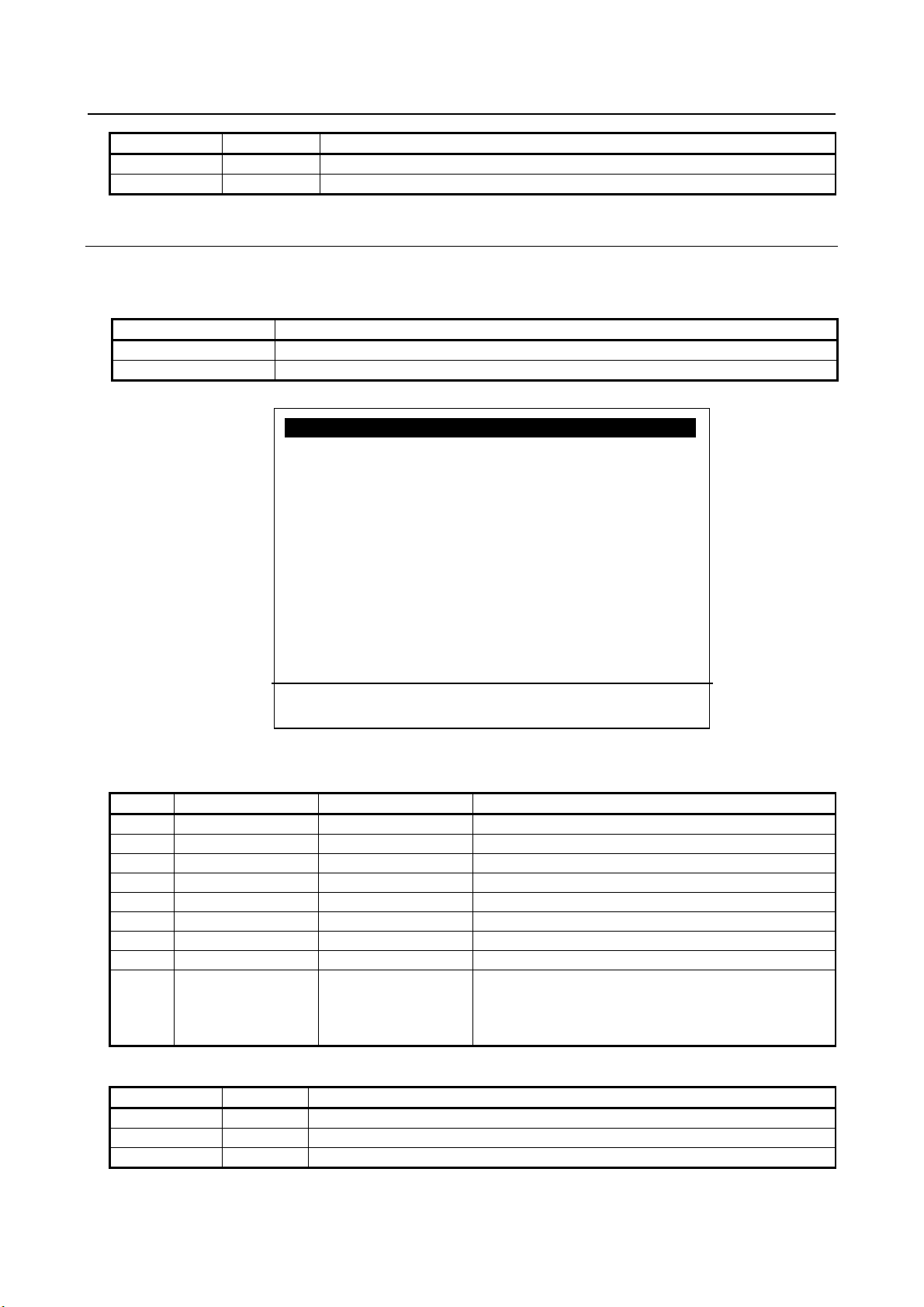
B-82864EN/09 8. SETUP PROFINET I-DEVICE
Function key
Words
Description of function keys
F2
detail
Go to Module Detail screen of the selected submodule.
F3
Other
Selection of setup screens.
Item name
Property name in GSDML file (use PROFINET-XML viewer to open the file)
ModId
Module Ident Number
SubslotId
Submodule Ident Number
I/O Device : Module 1 1/6
1. Slot : 1
Subslot : 1001
Comment :
2. [ ]
ModId(hex) : 0x000000
42
SubslotId(hex) : 0x00002e6f
Input Length 0
Output Length 16
Module type : I/O
3. Data type : [Digital]
[ TYPE ] list prev next
Setup PROFINET IO JOINT 10 %
#
Item
Adjustable values
Description
1
Slot - Slot number of the module
Sub - Sub slot number of the module
2
Comment
String[24]
Explanation of the module
ModId
-
Module Id of the module
SubslotId
-
Subslot Id of the module
Input Length
-
Input data length of the module in byte
Output Length
-
Output data length of the module in byte
Module type
-
Type of module (I/O, Safety, Transfer, None).
doesn’t have any effect on PROFINET I/O exchange.
Function key
Words
Description of function keys
F2
list
Go to module list screen
F3
prev
Go to previous module
F4
next
Go to next module
8.2.3.2 Module Detail Screen
The parameters of the module are displayed in this screen.
Table 8.2.3.2 (a) Property name in GSDML file
Fig. 8.2.3.2 (a) Module detail screen
Table 8.2.3.2 (b) Module detail screen
3 (a) Data type Digital
(a) Need to cycle power to have the change applied.
Analog
- 43 -
Choose from digital and analog.
It specifies if the process data is assigned to DI/DO or
AI/AO. 1Byte module can’t be assigned to analog. It
Page 54

8. SETUP PROFINET I-DEVICE B-82864EN/09
NOTE
Safety module, therefore don’t set subslot ID 0x1001-0x1008 on other modules.
1 Module parameters are set by TIA Portal.
Subslot ID 0x1001-0x1008 are reserved for PROFINET Safety module,
therefore don’t set subslot ID 0x1001-0x1008 on other modules.
2 PROFINET Safety option is required to use safety module. Only one safety
module is possible. Subslot ID 0x1001-0x1008 are reserved for PROFINET
8.2.4 Setup Configuration List Screen
Setup Configuration List Screen is the same as that of PROFINET I/O function. Please refer to 3.4.4 for
more detail.
8.3 STATUS SCREENS
Status screens are the same as those of PROFINET I/O function. Please refer to the chapter 4 for more
detail. This section explains the information screen for PROFINET I-device function. To open this screen,
please press the [Other]/F3 and select “Info” from Fig. 4.1 (a) status module list screen. In this screen,
you can confirm IP address, subnet mask, etc. currently configured.
Fig. 8.3 (a) Information screen
8.4 DEVICE SWITCHING TP INSTRUCTIONS
Device switching TP instructions of PROFINET I-device function are the same as those of PROFINET
I/O function. Please refer to the chapter 5 for more detail.
8.5 XDB BACKUP FUNCTION
Robot controller can take a backup of network configuration by reading out an XDB file from CP1604
PROFINET communication board.
The backup will be done automatically at the following events:
- Before communication start at Hot Start or Cold Start
- Before communication start when the start mode is changed from STOP to RUN on the PROFINET
Setup General screen
- 44 -
Page 55

B-82864EN/09 8. SETUP PROFINET I-DEVICE
Alarm
System variable
PRIO-655
$PNG2_DL2.$BXDB_SEV1
PRIO-656
$PNG2_DL2.$BXDB_SEV1
PRIO-657
$PNG2_DL2.$BXDB_SEV2
PRIO-662
$PNG2_DL2.$BACKUP_SEV
PRIO-668
$PNG2_DL2.$XDBCHK_SEV
Value
Severity
0
STOP
1
PAUSE
2
WARN
3
NOTE
5
SYSTEM
This function is enabled when the bit 1(2) of system variable $PNG2_DL2.$K_BACKUP is ON.
e.g.) $PNG2_DL2.$K_BACKUP = 3(Enable), $PNG2_DL2.$K_BACKUP = 1(Disable)
Cycle power is needed for change to take effect. The backup destination is specified by
$PNG2_DL2.$BACK_XDB.
First of all, the backup process checks the XDB file specified by $PNG2_DL2.$BACK_XDB.
If the XDB file exists, the file is compared to the XDB file in CP1604.
- In case of match, the process ends and the backup is skipped. Any alarm isn’t posted.
- In case of mismatch, the process continues for taking a backup.
- In case the comparison fails by internal error, following alarm is posted and the process ends.
PRIO-668 WARN "PNIO(C): XDB backup check failed"
If the XDB file does not exist, the process continues for taking a backup. Next, the following alarms are
posted when the process starts taking a backup.
PRIO-662 STOP "PNIO: Backup is running"
PRIO-655 WARN "PNIO: XDB backup started"
The following alarm is posted if the backup is successful.
PRIO-656 WARN "PNIO: XDB backup finished"
The following alarm is posted if the backup is failed, for example, when the file cannot be written to the
specified backup destination etc.
PRIO-657 WARN "PNIO: XDB backup failed"
The timeout of the backup is specified by $PNG2_DL2.$COLD_TIMEO. The default is 300 seconds.
The backup fails if it is not completed within this time.
The alarm severity of PRIO-655, PRIO-656, PRIO-657, PRIO-662, and PRIO-668 is set by the following
system variables.
Table 8.5 (a) Relationship of Alarm and system variable
PROFINET communication is going to start after the backup process regardless of the backup succeeds
or fails. To know the failure of backup, monitor PRIO-657 and PRIO-668. The state of XDB backup is
set to $PNG2_DIAG2.$BACKUP_STAT.
Table 8.5 (b) Alarm severity
- 45 -
Page 56

8. SETUP PROFINET I-DEVICE B-82864EN/09
Value
Definition
0
XDB backup has not executed yet / boot up of controller (initial state)
1
XDB backup started (on going)
2
XDB check failed, (process ended with failure)
3
XDB exists, is same (process ended OK)
4
XDB exists but is different, backup processing started (on going)
5
XDB does not exists, backup processing started (on going)
6
XDB file writing failed, (process ended with failure)
7
Timeout, (process ended with failure)
8
Backup process successfully ended (process ended OK)
NOTE
Cycle power is needed for change to take effect.
Table 8.5 (c) $PNG2_DIAG2.$BACKUP_STAT
The value returns to 1 when backup process starts. $PNG2_DIAG2.$BACKUP_STAT changes as
following figure.
Fig. 8.5 (a) $PNG2_DIAG2.$BACKUP_STAT
- 46 -
Page 57

B-82864EN/09 9. PROFINET FANUC board
Number of submodules
Number of input
Number of output
2
3192
3192
16
2688
2688
36
2048
2048
NOTE
512 bytes.
9 PROFINET FANUC board
This chapter describes the PROFINET function of the FANUC PROFINET board.
9.1 OVERVIEW
The maximum number of digital I/O of I/O controller and I/O Device is total 8192 points. To increase the
number of points used, increase the number of digital I/O at the maximum number of control start. The
analog I/O of the I/O controller and I/O device is not supported.
The actual usable data size is calculated as below.
(Total input data of I/O controller and I/O device [byte]) + (Total output data of I/O controller and I/O
device [byte]) + {8 × (The number of submodules of I/O controller and I/O device)} < 800 bytes
Table 9.1 (a) The number of I/O points and submodules
If the value on the left side exceeds 512 bytes, please use Mainboard C (Force Sensor, High-speed
communication CPU, for IO-Link i slave).
The I/O controller function has the following restrictions.
1 The enabled / disabled state of the device is not restored when the power is restored.
2 PRIO-621 does not occur even when there is no communication with the device.
Check the connection status with the device on the Setting List Screen in Section 3.4.4. If necessary,
make sure that the device is connected by the I/O value of the device. For example, if a device is
connected, make sure that one point of the device's input signal is ON.
3 Appendix F HANDLING ALARM STORM is not supported.
The models other than R-30iB Plus do not support the high-speed
communication CPU. Therefore, the actual usable data size should not exceed
- 47 -
Page 58

9. PROFINET FANUC board B-82864EN/09
Option software
Ordering specification
Description
supported on Single Channel only.
This function can be set with iPendant.
manual.
Option hardware
Ordering specification
Description
PROFINET FANUC BOARD
A05B-2600-J084
Mini-slot size PROFINET board manufactured
by FANUC
Option hardware
Ordering specification
Description
R-30iB Plus Mainboard C (Force
C.
NOTE
before 02B, please contact your local FANUC representative.
9.2 SOFTWARE
Table 9.2 (a) Option software of PROFINET FANUC board
PROFINET FANUC board A05B-2600-S523 PROFINET consists of mini slot size
PROFINET board made by FANUC. This
function cannot coexist with PROFINET
I-device function or Dual Channel PROFINET
function. Software series 7DF4 or 7DF5 is
required. Additionally, this function is
PROFINET FANUC board Single
/ Dual Channel
PROFINET Safety A05B-2600-J931 This option software is for safety
A05B-2600-S536 The PROFINET function is realized by
inserting a PROFINET FANUC board into the
mini-slot. In addition to the functions of the
PROFINET FANUC board (A05B-2600-S523),
this function allows subnetting of I/O
communication. Cannot coexist with other
PROFINET functions. Additionally, this
function is supported on 7DF5 only.
communication on PROFINET.
For PROFINET Safety function, please refer
to “Dual Check Safety Function OPERATOR’S
MANUAL (B-83184EN)” in addition to this
Please check the overall version number of PROFINET FANUC board before
setting the channel mode to Dual Channel. If it was PROFINET FANUC board
9.3 HARDWARE
9.3.1 Ordering specification
Table 9.3.1(a) Hardware option of PROFINET FANUC board
Table 9.3.1(b) R-30iB Plus Mainboard C
A05B-2670-H003 With the high-speed communication CPU, the
Sensor, High-speed
communication CPU for IO Link i
slave)
- 48 -
performance of PROFINET can be improved.
If the actual usable data size in Section 9.1
exceeds 512 bytes, be sure to use mainboard
Page 59
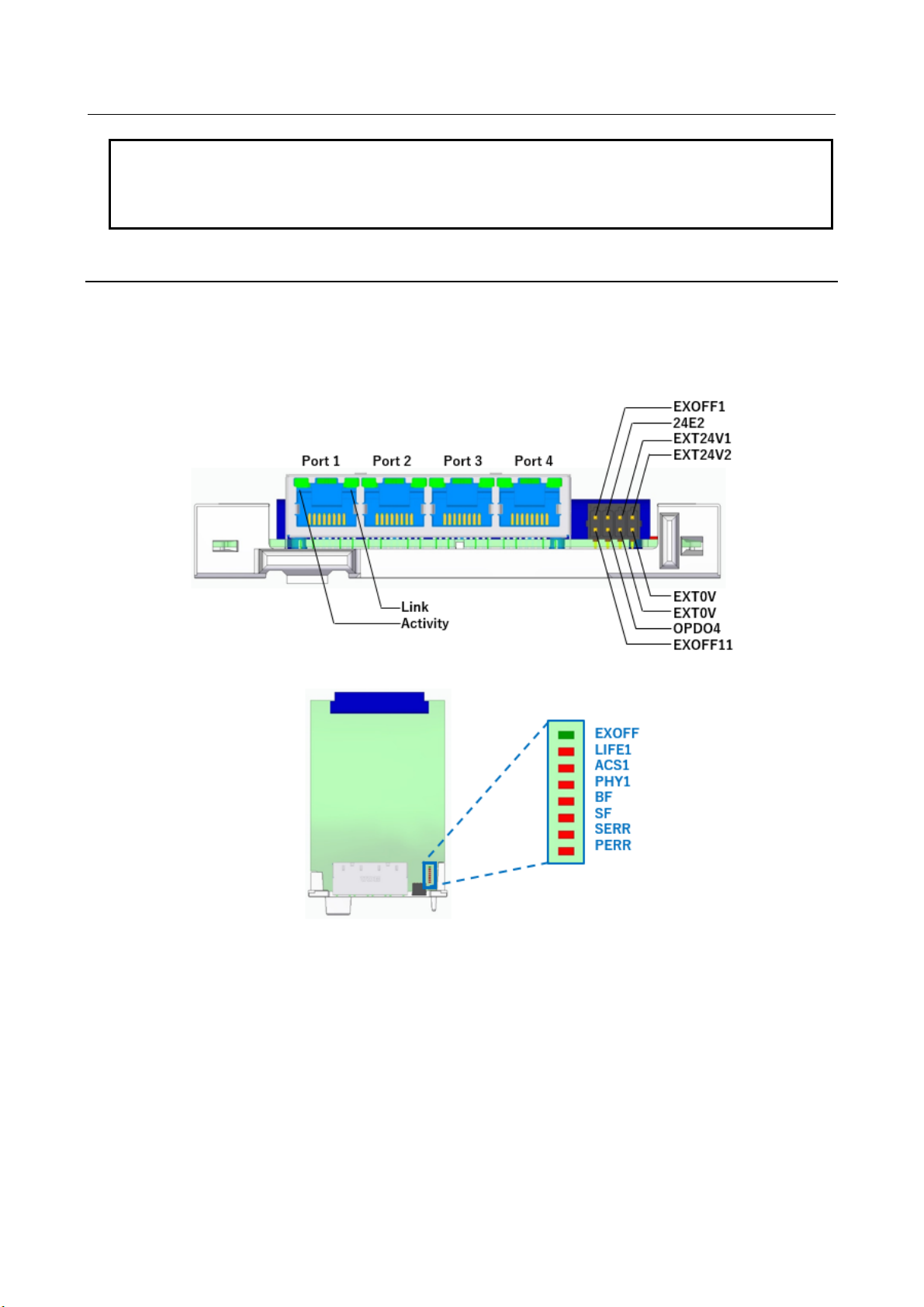
B-82864EN/09 9. PROFINET FANUC board
NOTE
should not exceed 512 bytes.
The models other than R-30iB Plus do not support the high-speed
communication CPU. Therefore, the actual usable data size in Section 9.1
9.3.2 Details of HARDWARE
The PROFINET FANUC board has four Ethernet ports and an external power supply connector as shown
in Fig. 9.3.2(a). Please refer to Fig. 9.3.2(b) for a PROFINET FANUC board with a total edition 02B or
later. The external power supply is for PROFIenergy function. Please refer to Chapter 11 for details of
PROFIenergy function. Please refer to Table 9.3.2(a) for more information on the LEDs on the board.
Fig. 9.3.2 (a) PROFINET FANUC BOARD with a total edition 01A
- 49 -
Page 60

9. PROFINET FANUC board B-82864EN/09
LED name
Color
Status
Description
Link
Orange
Lighting
Connection established
Activity
Green
Lighting
Sending and receiving data
-
Off
Link established
Red
Lighting
Link error occurred
-
Off
Normal
Red
Blinking
DCP LED flash
SERR
Red
Lighting
System error occurred
PERR
Red
Lighting
Parity error occurred
PHY1
Red
Lighting
Reserved
ACS1
Red
Lighting
Reserved
LIFE1
Red
Lighting
Reserved
EXOFF
Green
Off
Reserved
Table 9.3.2 (a) PROFINET FANUC BOARD LEDs
BF
SF
Fig 9.3.2 (b) PROFINET FANUC board with a total edition 02B or later
- 50 -
Page 61

B-82864EN/09 9. PROFINET FANUC board
9.3.3 Details of Ethernet ports
The PROFINET FANUC board has four Ethernet ports as shown in Figs. 9.3.3(a), 9.3.3(b). Figs. 9.3.3(a),
9.3.3(b) show the details of Ethernet port assignment for Single and Dual Channels. If you chose the
Dual Channel mode, port 1 and port 2 are I/O Device, port 3 and port 4 are I/O Controller, respectively.
Fig. 9.3.3 (a) PROFINET FANUC board (Single Channel) (01A)
Fig. 9.3.3 (b) PROFINET FANUC board (Dual Channel) (01A)
- 51 -
Page 62

9. PROFINET FANUC board B-82864EN/09
Fig. 9.3.3 (c) PROFINET FANUC board (Single Channel) (02B or later)
Fig. 9.3.3 (d) PROFINET FANUC board (Dual Channel) (02B or later)
- 52 -
Page 63
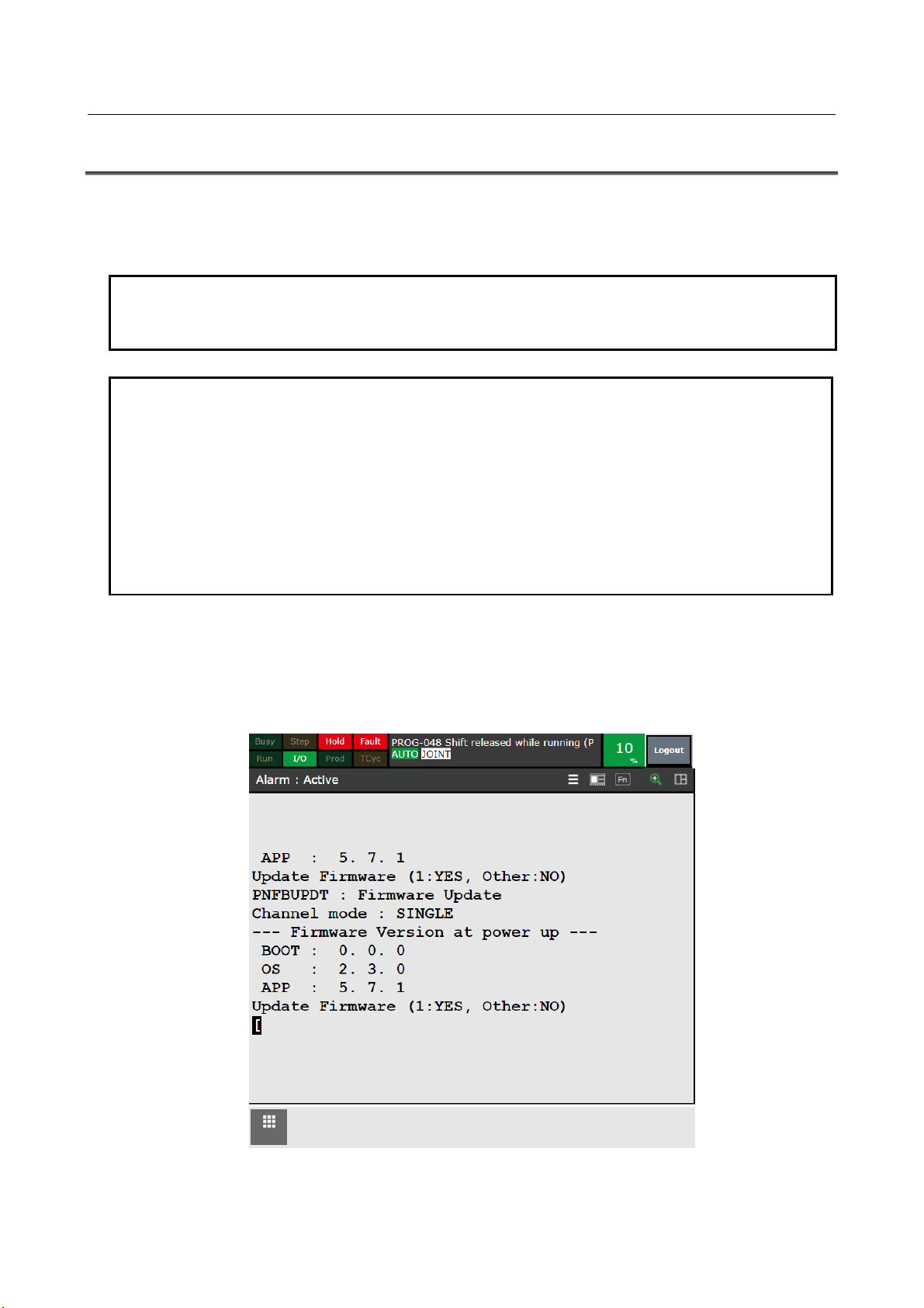
B-82864EN/09 9. PROFINET FANUC board
NOTE
NOTE
problem when in use.
9.4 PROFINET FANUC board firmware
There are three types of PROFINET FANUC board firmware: Boot, OS, and App, all of which must be
compatible with the robot controller software. For different versions, you need to update the firmware by
following the steps below.
Please use a PROFINET FANUC board with a total edition 03C or later in order
to set the channel mode to Dual Channel with 7DF5/29 or later.
If the firmware version does not match with the software of the robot controller,
PRIO-649 is displayed. PRIO-649 is displayed when you also change the
channel mode. Please update the firmware following procedure when this alarm
displayed.
In addition, if you use the software of the robot controller before 7DF4/07 or
7DF5/19, the PRIO-649 will not be displayed. However, a firmware update must
be performed. After executing the firmware update and rebooting, the version
display on the BOOT screen may not be displayed correctly. It has no practical
The firmware is updated by a KAREL pnfbupdt.pc. Open the list screen with the SELECT key and
execute pnfbupdt.pc. When you press the [MENU] key to open the user screen, the following screen is
displayed. Press the key 1 to update, or press other key not to update. Please check the channel mode
displayed on the Firmware Update screen before updating the firmware. If you press the key 1, it will be
updated to the version displayed on the screen.
Fig. 9.4 (a) Firmware Update screen (Single Channel)
- 53 -
Page 64
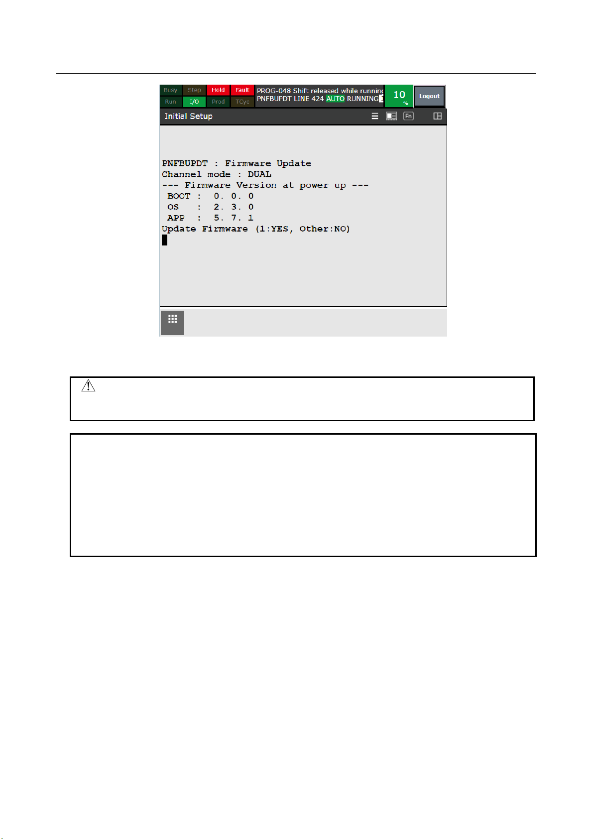
9. PROFINET FANUC board B-82864EN/09
NOTE
WARNING
corrupted and the PROFINET FANUC board may stop working.
Fig. 9.4 (b) Firmware Update screen (Dual Channel)
Never turn off the power while updating the firmware. The firmware may be
Depending on the firmware version, the following message may be displayed
after updating the App when run pnfbupdt.pc. Only if you see this message, turn
off the power and then run pnfbupdt.pc again in the same way.
* SKIP BOOT UPDATE *
***** Please RUN this program *****
***** again after cycle power *****
***** to update BOOT *****
- 54 -
Page 65

B-82864EN/09 9. PROFINET FANUC board
Number of ports and number of channel
4 ports
(single channel)
4 ports
(dual channel)
7DF5P/05 or later,
up to V9.40P/23)
7DF5P/24 or later
7DF5P/35 or later
(V9.40P/24 or later)
(V9.40P/35 or later)
R-30iB Mate Plus
Open Air
No support.
No support.
No support.
(V9.40P/24 or later)
(V9.40P/35 or later)
7DF5P/19 or later,
up to V9.40P/23)
7DF5P/24 or later
7DF5P/35 or later
H/W Platform
Model
File name
Vendor ID
Device ID
36P4P-20220112.xml
7DF5 (V9.40P)
R-30iB Plus
GSDML-V2.41-Fanuc-A05B2600S523V9
40P4P-20210921.xml
0x01B7
0x20
R-30iB Mini Plus
GSDML-V2.41-Fanuc-A05B2600S523V9
40X4P-20211018.xml
0x01B7
0x21
R-30iB Mate Plus
GSDML-V2.41-Fanuc-A05B2600S523V9
40M4P-20211026.xml
0x01B7
0x22
R-30iB Compact Plus
GSDML-V2.41-Fanuc-A05B2600S523V9
40C4P-20211027.xml
0x01B7
0x23
NOTE
addition to this manual.
9.5 SUPPORTED ROBOT CONTROLLER
The robot controller and the software version show in the following table supports PROFINET FANUC
board. The robot controller not listed in the following table does not support PROFINET FANUC board.
PROFINET FANUC Board (A05B-2600-S523) and PROFINET FANUC Board Single/Dual Channel
(A05B-2600-S536) are non-safety communication software. For safety communication, please order
PROFINET Safety function (A05B-2600-J931) in addition either of these option software. For PROFINET
Safety function, please refer to “Dual Check Safety Function OPERATOR’S MANUAL (B-83184EN)” in
Table 9.5 (a) Robot controller that support PROFINET FANUC board
Robot controller
R-30iB Plus
R-30iB Mate Plus
R-30iB Compact Plus
R-30iB Mini Plus
up to 7DF5P/23
(V9.40P/05 or later,
No support. 7DF5P/24 or later
No support. 7DF5P/24 or later
up to 7DF5P/23
(V9.40P/19 or later,
1 port
(V9.40P/24 or later)
(V9.40P/24 or later)
(V9.40P/35 or later)
7DF5P/35 or later
7DF5P/35 or later
(V9.40P/35 or later)
9.6 GSDML
GSDML file is used by the configuration software. The GSDML file contains information about the
device as a PROFINET device. When setting the I/O controller that communicates with the robot
controller, read the GSDML file into the I/O controller setting software and use it. FANUC provides the
GSDML file.
Table 9.6 (a) GSDML file (Single Channel)
7DF4 (V9.36P) R-30iB Plus GSDML-V2.42-Fanuc-A05B2600S523V9
0x01B7 0x20
- 55 -
Page 66

9. PROFINET FANUC board B-82864EN/09
H/W Platform
Model
File name
Vendor ID
Device ID
7DF5 (V9.40P)
R-30iB Plus
GSDML-V2.42-Fanuc-A05B2600S536V9
40P2P-20220518.xml
0x01B7
0x24
R-30iB Mini Plus
GSDML-V2.42-Fanuc-A05B2600S536V9
40X2P-20220518.xml
0x01B7
0x25
R-30iB Mate Plus
GSDML-V2.42-Fanuc-A05B2600S536V9
40M2P-20220518.xml
0x01B7
0x26
R-30iB Compact Plus
GSDML-V2.42-Fanuc-A05B2600S536V9
40C2P-20220518.xml
0x01B7
0x27
NOTE
channel mode and supported model before use.
Table 9.6 (b) GSDML file (Dual Channel)
The GSDML file is different for Single and Dual Channels. Please check the
9.7 INPUT SIGNALS AT COMMUNICATION FAILURE
If I/O Device communication fails, “PRIO-621 PNIO(D) device is not running” shows up.
Input signals of I/O Device are cleared if IOPS = BAD, at power up and when the connection is lost.
IF I/O Controller communication fails, “PRIO-622 PNIO(C) controller is not running” shows up.
Input signals of I/O Controller are cleared if IOPS = BAD, at power up and when the connection is lost.
- 56 -
Page 67

B-82864EN/09 10. SETUP PROFINET FANUC board
WARNING
before changing the start up mode to RUN.
10 SETUP PROFINET FANUC board
10.1 OVERVIEW
This section describes the procedure for setting the PROFINET FANUC board.
1 Create the configuration files required for PROFINET network settings and copy them to the
FR:¥pnfb directory of the robot controller. Please refer to Section 10.5 for details. Set the IP address
and device name of PROFINET. You can use a Siemens configuration tool (TIA Portal, PRONETA)
to set the IP address and device name. Please refer to Section 10.6 for details. When performing this
work, switch the start mode to STOP in order to stop the PROFINET board.
2 Set Enable/Disable of I-Device and I/O Controller on the Setup General Screen.
3 Set the number of I/O points on the Setup I-Device Screen and the Setup I/O Controller Screen.
4 Restart the robot controller.
5 Check I/O assignment of PROFINET. If it does not connect, change the I/O assignment and restart
the robot controller.
6 Switch start mode STOP to RUN on the Setup General Screen.
Changing start mode to RUN, the PROFINET input/output signals of the robot
controller activates. Please verify I/O assignment of the robot controller is done
and correct before changing the start up mode to RUN. Please verify the safety
is assured and make sure if it is safe to start PROFINET I/O data exchange
7 Changing start mode to RUN, the configuration files are installed from the FR:¥pnfb of the robot
controller to PROFINET board. If the configuration files are not found in the FR:¥pnfb directory,
upload the configuration file currently loaded on the PROFINET board to the FR:¥pnfb directory.
8 If there are any errors, check the configuration created by the configuration tool to fix the error. To
download configuration again, and change the start up mode to STOP.
9 If there is no error, check PROFINET I/O data exchange.
10 Do additional setting to the configuration read in from PROFINET board.
11 Turn off the robot controller.
12 The additional setting will be activated at next power up.
- 57 -
Page 68

10. SETUP PROFINET FANUC board B-82864EN/09
10.2 SETUP SCREENS
10.2.1 Setup General Screen
Use this screen to select start mode, and to change Enable/Disable of I/O Controller and I/O Device.
Press the F3 key to show up the pop-up menu to open other screens. Press the F10 key (press NEXT and
then press the F5) to clear I/O assignment.
Fig. 10.2.1 (a) Setup general screen (Single channel)
Fig. 10.2.1 (b) Setup general screen (Dual channel)
- 58 -
Page 69

B-82864EN/09 10. SETUP PROFINET FANUC board
#
Item
Adjustable values
Description
1
Max. digital port
number
-
Displays max digital port number
2
Start mode
STOP
STOP :
PROFINET stops by changing start mode to STOP.
Channel mode
7DF5/29 or later.
DISABLE
Enable/Disable of I/O Controller
DISABLE
Enable/Disable of I-Device
Device ID
-
Device ID stored to configuration in PROFINET board.
Vendor ID
-
Vendor ID stored to configuration in PROFINET board.
7DF5/29 or later.
7 ENABLE
DISABLE
Enable/Disable of DCP Client
Initial value : ENABLE
Initial value : DISABLE
9 0 ~
Number of using Sign off signal
Initial value : 0
By pressing “Execute”, resetting firmware is attempted.
executing.
Function key
Words
Description
F2
PEF
Unused
F3
Other
Selection of setup screens
F10
CLR_ASG
Clear I/O assignments
Table 10.2.1 (a) Setup general screen items
RUN
3(a)
4(a) I/O Controller ENABLE
5(a) I-Device ENABLE
6 Upload Setup file ENABLE
SINGLE
DUAL
DISABLE
PROFINET does not start automatically at power up.
RUN :
PROFINET starts automatically at power up.
STOP -> RUN :
PROFINET starts by changing start mode to RUN.
RUN -> STOP :
SINGLE :
Single channel I/O communication.
DUAL :
Dual channel I/O communication.
Port 1 and port 2 are I/O Device, port 3 and port 4 are
I/O Controller, respectively.
(Requires A05B-2600-S536 to use this function)
Initial value : SINGLE
This item is always displayed if the software version is
Initial value : ENABLE
Initial value : ENABLE
Enable/Disable of upload setup file
Initial value : ENABLE
This item is always displayed if the software version is
8 ENABLE
DISABLE
10 Reset firmware -
(a) Need to cycle power to have the change applied.
Enable/Disable of Sign off
(Requires A05B-2600-J638 or A05B-2600-J639 to use
this function)
(Requires A05B-2600-J638 or A05B-2600-J639 to use
this function)
Please switch the start mode to STOP before
- 59 -
Page 70

10. SETUP PROFINET FANUC board B-82864EN/09
WARNING
before changing the start up mode to RUN.
NOTE
STOP.
NOTE
complete.
values
instruction described in Section 10.4.
NOTE
Them might not be set up correctly.
Changing start mode to RUN, the PROFINET input/output signals of the robot
controller activates. Please verify I/O assignment of the robot controller is done
and correct before changing the start up mode to RUN. Please verify the safety
is assured and make sure if it is safe to start PROFINET I/O data exchange
The comment of modules is erased when the network configuration is read in.
To recover the comment, please write it down before changing start up mode to
The configuration file has a limit to the number of times it can be written, we
recommend setting it to "Upload Setup file : DISABLE" after the startup is
10.2.2 Setup I/O Controller Screen
Setup I/O Controller Screen is the same as that of PROFINET I/O function. Please refer to Subsection
3.4.2.
10.2.3 Setup I-Device Screen
Setup I-Device Screen is the same as that of PROFINET I-device function. Please refer to Subsection
8.2.3.
Module List Screen and Module Detail Screen do not support the display of modules on the device.
10.2.4 Setup Configuration List Screen
Setup Configuration List Screen is the same as that of PROFINET I/O function. Please refer to
Subsection 3.4.4.
Configuration Detail Screen differs from that of PROFINET I/O function only in the following item.
# Item Adjustable
2 Show error when deactivated Off
On
If this item is Off, an error message is not show
up when the device is disconnected by TP
Description
10.2.5 Setup Ethernet Address Screen
Use this screen to setup Ethernet address of I/O Device and I/O Controller.
Please enter the IP Address, Subnet Mask and Router Address without spaces.
- 60 -
Page 71

B-82864EN/09 10. SETUP PROFINET FANUC board
#
Item
Adjustable values
Description
55.255]
2
Subnet Mask
[0.0.0.0]-[255.255.2
55.255]
Subnet mask of I/O Device or I/O Controller
55.255]
4
Device Name
0-32
Device name of I/O Device or I/O Controller
alphabetical or numeric characters.
Fig. 10.2.5 (a) Setup Ethernet address screen (Single Channel)
Table 10.2.5 (a) Setup Ethernet address screen items (Single Channel)
1 IP Address [0.0.0.0]-[255.255.2
3 Router Address [0.0.0.0]-[255.255.2
IP address of I/O Device or I/O Controller
Router address of I/O Device or I/O Controller
Please set the device name in lowercase
Fig. 10.2.5 (b) Setup Ethernet address screen (Dual Channel)
- 61 -
Page 72

10. SETUP PROFINET FANUC board B-82864EN/09
#
Item
Adjustable values
Description
1
IP Address
[0.0.0.0]-[255.255.2
55.255]
IP address of I/O Device
from the subnet mask of the I/O Controller.
3
Router Address
[0.0.0.0]-[255.255.2
55.255]
Router address of I/O Device
alphabetical or numeric characters.
5
IP Address
[0.0.0.0]-[255.255.2
55.255]
IP address of I/O Controller
from the subnet mask of the I/O Device.
7
Router Address
[0.0.0.0]-[255.255.2
55.255]
Router address of I/O Controller
alphabetical or numeric characters.
Function key
Words
Description
F1
TYPE
Selection of setup screens
F2
APPLY
Application of changes
F3
Other
Selection of setup screens
F10
CLR_ASG
Clear I/O assignments
Table 10.2.5 (b) Setup Ethernet address screen items (Dual Channel)
2 Subnet Mask [0.0.0.0]-[255.255.2
55.255]
4 Device Name 0-32 Device name of I/O Device
6 Subnet Mask [0.0.0.0]-[255.255.2
55.255]
8 Device Name 0-32 Device name of I/O Controller
Subnet mask of I/O Device
This item should be set to the values different
Please set the device name in lowercase
Subnet mask of I/O Controller
This item should be set to the values different
Please set the device name in lowercase
10.3 I/O CONFIGURATION
I/O Configuration Screen is the same as that of PROFINET I/O function. Please refer to Chapter 4.
10.4 DEVICE SWITCHING TP INSTRUCTIONS
Device switching TP instructions are the same as those of PROFINET FANUC board function. Please
refer to Chapter 5.
- 62 -
Page 73

B-82864EN/09 10. SETUP PROFINET FANUC board
Name
Description
Please refer to Subsection 10.5.2 for details.
tic.zip
This is a configuration file for I/O Controller communication. This file is load to the
Please refer to Subsection 10.5.3 for details.
communication. Please refer to Subsection 10.5.4 for details.
bas_cm_api.ini
This is a configuration file for PROFINET FANUC BOARD. This file will be uploaded
be created.
<?xml version="1.0" encoding="utf-8"?>
<Submodule API="0" Subslot="1" ID="0x00000001" Inputlen="0" Outputlen="0"
</Device>
10.5 CONFIGURATION FILE
10.5.1 Configuration File List
Create the configuration file required to communicate with the PROFINET FANUC board and copy it to
the FR:¥pnfb¥ directory.The required configuration files are listed in Table 10.5.1 (a). Also, the file
name must be the same as in Table 10.5.1 (a).
Table 10.5.1 (a) Configuration file list
device1.zip This is a configuration file for I/O Device communication. This file is load to the
PROFINET FANUC BOARD from the FR:¥pnfb directory when communication starts.
PROFINET FANUC BOARD from the FR:¥pnfb directory when communication starts.
dev_config.dt This file contains device information (device name, station ID, etc.) for I/O controller
from the PROFINET FANUC BOARD for backup at power on. This file does not need to
10.5.2 Creating device1.zip
device1.zip is a configuration file required for I/O Device communication. Use any text editor to create
device1.xml, ZIP-compress it with the name device1.zip, and copy it to the FR:¥pnfb directory.
device1.zip in the FR:¥pnfb directory will be loaded into the PROFINET board at the start of
communication.
The format of device1.xml of Single and Dual Channel are shown below. Please use it as it is without
changing the following parts.
Single Channel
<Device>
<Module Slot="0" ID="0x00000300">
IMCarrier="1" />
<Submodule API="0" Subslot="0x8000" ID="0x00008000" Inputlen="0" Outputlen="0" />
<Submodule API="0" Subslot="0x8001" ID="0x00008001" Inputlen="0" Outputlen="0" />
<Submodule API="0" Subslot="0x8002" ID="0x00008002" Inputlen="0" Outputlen="0" />
<Submodule API="0" Subslot="0x8003" ID="0x00008003" Inputlen="0" Outputlen="0" />
<Submodule API="0" Subslot="0x8004" ID="0x00008004" Inputlen="0" Outputlen="0" />
</Module>
- 63 -
Page 74

10. SETUP PROFINET FANUC board B-82864EN/09
<?xml version="1.0" encoding="utf-8"?>
<Submodule API="0" Subslot="1" ID="0x00000001" Inputlen="0" Outputlen="0"
</Device>
<Module Slot="1" ID="8">
</Module>
Element
Value
Description
Slot
1
A number (1-8) that indicates the order of the modules.
Numbers 1 to 8 are assigned in order from the front. (Cannot be
duplicated)
ID
8
A number (1-8) that indicates the kind of the modules.
hexadecimal numbers can be used as the ID value, but
Table 10.5.2 (c) is displayed in decimal number and Table 10.5.2 (d) is
I / O modules in Table 10.5.2
(d) can only be set to Slot = 1.
Element
Value
Description
API
0
always 0
Subslot
01
always 01
ID
0x00000001
always 0x00000001
Inputlen
4
Specify a number of input points in byte (8 points) units.
This values corresponding to the IDs in Table 10.5.2 (c) and (d)
Outputlen
0
Specify a number of output points in byte (8 points) units.
This values corresponding to the IDs in Table 10.5.2 (c) and (d)
Dual Channel
<Device>
<Module Slot="0" ID="0x00000300">
IMCarrier="1" />
<Submodule API="0" Subslot="0x8000" ID="0x00008000" Inputlen="0" Outputlen="0" />
<Submodule API="0" Subslot="0x8001" ID="0x00008001" Inputlen="0" Outputlen="0" />
<Submodule API="0" Subslot="0x8002" ID="0x00008002" Inputlen="0" Outputlen="0" />
</Module>
Set the I/O Device by writing up to 8 modules of I/O module and safety I/O module after </ Module>.
The number of input and output points of the I/O Device is the total of the modules. It is necessary to
select the same module when setting the I/O Device with the PLC setting tool. The settings for each
module consist of the following three lines. Table 10.5.2 (a) for module elements, Table 10.5.2 (b) for
submodule elements, Table 10.5.2 (c) for I/O module elements, and safety I/O module elements refer
Table 10.5.2 (d) for details.
<Submodule API="0" Subslot="01" ID="0x00000001" Inputlen="4" Outputlen="0" />
Table 10.5.2 (a) Elements of Module
Please refer to Table 10.5.2(c), (d) for details.
Both decimal and
displayed in hexadecimal number. The safe
Table 10.5.2 (b) Elements of Submodule
- 64 -
Page 75

B-82864EN/09 10. SETUP PROFINET FANUC board
ID (dec)
Inputlen
Outputlen
Description
1 1 1
Input 8 points. Output 8 points.
2 1 0
Input 8 points.
3 0 1
Output 8 points.
4 2 2
Input 16 points. Output 16 points.
5 2 0
Input 16 points.
6 0 2
Output 16 points.
7 4 4
Input 32 points. Output 32 points.
8 4 0
Input 32 points.
9 0 4
Output 32 points.
10
16
16
Input 128 points. Output 128 points.
11
16 0 Input 128 points.
12 0 16
Output 128 points.
13
32
32
Input 256 points. Output 256 points.
14
32 0 Input 256 points.
15 0 32
Output 256 points.
16
64
64
Input 512 points. Output 512 points.
17
64 0 Input 512 points.
18 0 64
Output 512 points.
19
128
128
Input 1024 points. Output 1024 points.
20
128
0
Input 1024 points.
21 0 128
Output 1024 points.
ID (hex)
Inputlen
Outputlen
Description
0x2001
6 6 Safety input 8 points. Safety output 8 points.
0x2002
7 7 Safety input 16 points. Safety output 16 points.
0x2003
8 8 Safety input 24 points. Safety output 24 points.
0x2004
9 9 Safety input 32 points. Safety output 32 points.
0x2005
10
10
Safety input 40 points. Safety output 40 points.
0x2006
11
11
Safety input 48 points. Safety output 48 points.
0x2007
12
12
Safety input 56 points. Safety output 56 points.
0x2008
13
13
Safety input 64 points. Safety output 64 points.
<Module Slot="1" ID="19">
</Module>
<Module Slot="1" ID="0x2008">
</Module>
Table 10.5.2 (c) I/O module list
Table 10.5.2 (d) Safe I/O module list
The setting example is described below.
Example 1)
Slot 1: input 1024 points. output 1024 points
<Submodule API="0" Subslot="01" ID="0x00000001" Inputlen="128" Outputlen="128" />
Example 2)
Slot 1: Safety input 64 points. Safety output 64 points.
Slot 2: input 512 points. output 512 points.
<Submodule API="0" Subslot="01" ID="0x00000001" Inputlen="13" Outputlen="13" />
</Module>
<Module Slot="1" ID="16">
<Submodule API="0" Subslot="01" ID="0x00000001" Inputlen="64" Outputlen="64" />
- 65 -
Page 76

10. SETUP PROFINET FANUC board B-82864EN/09
10.5.3 Creating tic.zip
tic.zip is a configuration file required for I/O Controller communication. Create it using PLCnext
Engineer (*1), ZIP-compress the created file with the name tic.zip, and copy it to the FR:¥pnfb directory.
The tic.zip in the FR:¥pnfb directory is loaded into the PROFINET FANUC board when communication
starts. The procedure for creating tic.zip is explained below.
1 Start PLCnext Engineer, and select “Create a new project”.
2 Read the .fdcml file with “File → Import → Import FDCML 3.0 device description …”
The .fdcml file can be obtained from FANUC.
3 Read the .gsdml file of device I/O Controller communication with “File → Import → Import
GSDML file …” (Obtain the .gsdml file from the device manufacturer).
4 Select SW IOC from “Network → local → Devices → PLC” in the “Component” window and drag
and drop it into the “Plant” window to add the SW IOC.
5 Select modules from “Network → local → Devices → I/O → Interface modules” in the “Component”
window and drag and drop it into the “Plant” window to add the modules.
6 Additional parameter settings may be required depending on the device used. The Siemens
ET200SP requires the base module (light or dark) setting, so double-click the added module and set
it from the Parameter tab.
7 When building with Project → REBUILD, in addition to links.xml and sw-ioc-1.tic, as many .tic as
the number of added devices will be created (*2). ZIP-compress all of this with the name tic.zip.
(*1) PLCnext Engineer can be downloaded free from the PHOENIX CONTACT website.
(*2) Created in “
C:¥Users¥Public¥PLCnext Engineer¥Binaries¥*@binary¥RES_* ¥Arp.Io.PnC” by default.
10.5.4 Creating dev_config.dt
dev_config.dt contains device information (device name, station ID, etc.) for I/O Controller
communication. Create a dev_config.dt with any text editor, and change the extension to .dt.
By dev_config.dt copying to FR:¥pnfb¥ directory, read at power up and update the robot controller
setting. The following explains how to create dev_config.dt.
The version number is written on the first line. The version is 1.1. Enter the device information on the
second and subsequent lines. When entering device information, enter it in the format "slot [slot number].
Element = x". You can use slot numbers from 1 to 25. Use the elements in Table 10.5.4 (a) to specify the
device name, station ID, etc.
ver : 1.1
slot[1].name = dev01
slot[1].station_id = 201
slot[1].di_byte = 2
slot[1].do_byte = 2
slot[1].alias = device_1
slot[2].name = dev02
slot[2].station_id = 202
slot[2].di_byte = 2
slot[2].do_byte = 2
slot[2].alias = device_2
- 66 -
Page 77

B-82864EN/09 10. SETUP PROFINET FANUC board
Element
Description
name
Specify the device name. Up to 59 characters. (Cannot be duplicated)
station_id
Specify the station ID. (Cannot be duplicated)
di_byte
Specify the number of DI points to be assigned to the device in bytes (8 points).
do_byte
Specify the number of DO points to be assigned to the device in bytes (8 points).
alias
Specify any character string to be displayed instead of the device name.
NOTE
insert unnecessary line breaks.
Table 10.5.4 (a) Elements used in the dev_config.dt
Check if the device name described in the .tic file is in dev_config.dt at the start of communication. If
the .tic file matches the device name listed in dev_config.dt, the I/O data for that device is copied
between the DI/DO in the slot of the station ID.
As an example above, if the device name dev01 in dev_config.dt matches that in the .tic file, copy the
input / output data (2 bytes / 2 bytes) on device dev01 between the DI/DO in slot 201.
When specifying the device name, station ID, etc., the data cannot be read
correctly unless a space is entered before and after the =. In this case, the alarm
PRIO-721 "PNIO: dev_config.dt read failure (line:%d)" indicating a syntax error
is displayed. PRIO-721 will be displayed even if there is a blank line, so do not
10.6 DCP Client
DCP Client is supported as standard in PROFINET FANUC board. Switching between enable and
disable is executed on the Setup General Screen. Please refer to Subsection 10.2.1 for detail.
By enabling the DCP Client, PRONETA Basic (*1) can recognize the PROFINET FANUC board even
when PROFINET communication is stopped. The device name and IP address of PROFINET FANUC
board can be set from PRONETA Basic with this DCP Client enabled.
(*1) PRONETA Basic can be downloaded free from the Siemens website.
10.6.1 Setup device name and IP address
1. Please confirm to stop the PROFINET communication on Setup General Screen. If the start mode is
RUN, switch the start mode to STOP.
2. Connect the PROFINET FANUC board to the PC on which PRONETA Basic is installed.
3. Start PRONETA Basic. Then, the home screen will be displayed, so select “Network Analysis”.
4. After a while, the screen will switch to the screen shown in Fig. 10.6.1(a), and the current network
configuration will be displayed. In Fig. 10.6.1(a), the PLC, I / O module, PROFINET FANUC board
and PC are connected via an Ethernet switch.
- 67 -
Page 78

10. SETUP PROFINET FANUC board B-82864EN/09
Fig. 10.6.1 (a) PRONETA Online Screen
5. Place the cursor on the device you want to set and left-click in the Device Table - Online window.
Then the item will be marked in blue, so right-click here. When the property menu is displayed as
shown in Fig. 10.6.1 (b), select “Set Network Parameters”.
Fig. 10.6.1 (b) PRONETA properties menu
6. The Set Network Parameters window is displayed as shown in Fig. 10.6.1 (c). If you want to change
the device name, select “Assign Device Name”. If you want to change the IP address, select “IP
Configuration” and enter the value. Left-click “Set” to complete the settings.
- 68 -
Page 79
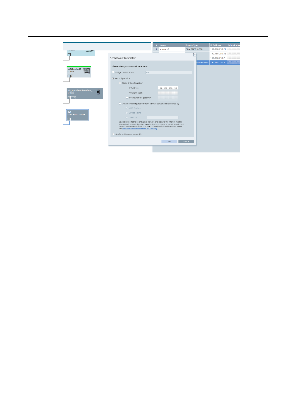
B-82864EN/09 10. SETUP PROFINET FANUC board
Fig. 10.6.1 (c) PRONETA Set Network Parameters window
7. Click the “Refresh” at the top left of the screen and check if the setting changes are applied.
- 69 -
Page 80

B-82864EN/09 11. PROFIenergy
Option software
Ordering specification
Description
function.
hardware
A cabinet, B cabinet
PROFINET FANUC BOARD
A05B-2600-K841
Siemens CP1604
A05B-2600-K840
11 PROFIenergy
This chapter describes the PROFIenergy (PE) option.
11.1 OVERVIEW
PE is a profile of the PROFINET communication protocol that allows you to manage the power
consumption of automated equipment in manufacturing over the PROFINET network, controlling energy
usage during planned and unplanned production interruptions.
This option has the following notes and restrictions:
1. Only supported on R-30iB and R-30iB Plus
2. One of the following option software is required to use this option.
- PROFINET FANUC board (A05B-2600-S523)
- PROFINET I-device (A05B-2600-J709)
- PROFINET I/O (A05B-2600-J930)
3. One of the following option hardware is required to use this option.
- PROFINET FANUC BOARD (A05B-2600-J084)
- Siemens PROFINET board CP1604 with PROFIenergy board (A05B-2600-J074)
4. In addition to the above, the following items are required to use this option.
- External power cable (Please refer to Subsection 11.3.1 for details)
- External power supply (Please use a commercially available one)
5. PROFINET FANUC board (A05B-2600-S523) does not support the functions in Section 11.5.
11.2 SOFTWARE
Table 11.2 (a) Option software basic information
This option software is necessary for PE
function that is PROFINET profile.
PROFIENERGY A05B-2600-J750
Please prepare external power cable and
external power supply, if you use PE
11.3 HARDWARE
11.3.1 Ordering specification
The specifications of the external power cable used in this option differ depending on the board.
Table 11.3.1 (a) Specification of the external power cable
In addition, if use PE in Siemens CP1604 (A05B-2600-J073), it is need to order the following board.
- 70 -
Page 81
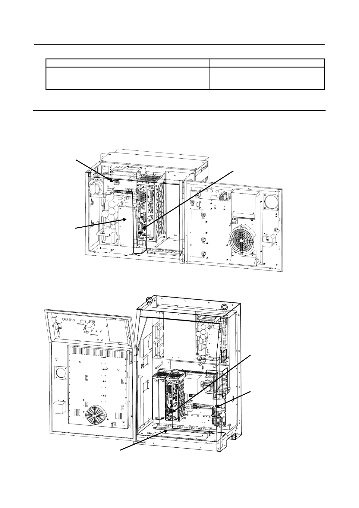
B-82864EN/09 11. PROFIenergy
Option hardware
Ordering specification
Description
This external board is attachment for
for using PE function.
Table 11.3.1 (b) Specification of the PROFIenregy board for CP1604
PROFIenergy Board A05B-2600-K170
Siemens CP1604 board (A05B-2600-J073)
11.3.2 Details of HARDWARE
Connect the cable depending on the system.
If you want to supply external 24V power to the PROFINET FANUC board, please use the connector
listed in Table 11.3.2.
Emergency stop board
CRMA93
PROFIenergy
connection cable
PROFINET FANUC BOARD
TBCP3
Fig. 11.3.2 (a) Path of the cable for PROFINET FANUC BOARD in A-cabinet
PROFINET FANUC BOARD
TBCP3
Emergency stop board
CRMA93
PROFIenergy
connection cable
Fig. 11.3.2 (b) Path of the cable for PROFINET FANUC BOARD in B-cabinet
- 71 -
Page 82
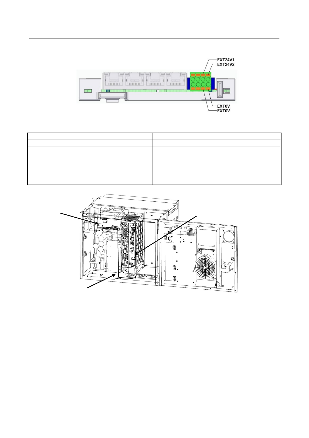
B-82864EN/09 11. PROFIenergy
Item
Specification
Voltage range of the 24V supplies
21.6 - 26.4V DC
FANUC specification : A63L-0002-0389#S08
Current consumption of the external 24V voltage
Max. 100mA
Please connect to EXT24V1 and EXT0V, or EXT24V2 or EXT0V.
Fig.11.3.2 (c) How to wire the external power supply at PROFINET FANUC board
Table 11.3.2 (a) Specification of external power supply of PROFINET FANUC board
Phoenix Contact Connector Manufacturer specification : 1715736 (for 01A)
Emergency stop board
CRMA93
FANUC specification : A63L-0002-0347#08L
Manufacturer specification : 1790124 (for 02B or later)
CP1604 board
TBCP2
PROFIenergy
connection cable
Fig.11.3.2 (d) Path of the cable for CP1604 board in A-cabinet
- 72 -
Page 83
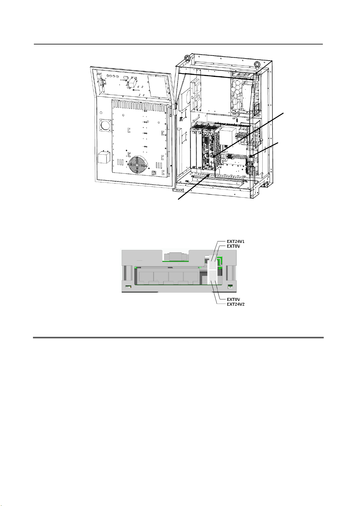
B-82864EN/09 11. PROFIenergy
CP1604 board
TBCP2
Emergency
stop board
CRMA93
PROFIenergy
connection cable
Fig.11.3.2 (e) Path of the cable for CP1604 board in B-cabinet
Please connect to EXT24V1 and EXT0V, or EXT24V2 or EXT0V.
Fig.11.3.2 (f) How to wire the external power supply at CP1604 board
11.4 PE Device function
After that, there is an explanation about system variables if you ordered PROFINET I/O (A05B-2600J930). If you ordered PROFINET I-device (A05B-2600-J709), please replace $PNIO with $PNG2, and if
you ordered PROFINET FANUC board (A05B-2600-S523), please replace $PNIO with $PNFB.
Power management is user specific application, and user needs to create his own PE application (KAREL
or TP) that reacts PE command from PE controller (= I/O Controller). This option provides application
interface (API) for PE application as system variables.
If this option isn’t ordered, PE command from PE controller is ignored as invalid index.
- 73 -
Page 84

B-82864EN/09 11. PROFIenergy
System variables
Description
$PNPE_IF.$ENABLE
1 = PE enabled (default), 0 = PE disabled.
controlled start.
$PNPE_IF.$SERV_NUM
The number of PE service (default 16) accommodated in system
changed, the number of array elements are changed at controlled start.
Name
In/Out
Type
Usage
$PNPE_IF.$RQ_ID
Input
UBYTE
Service_Request_ID
$PNPE_IF.$RQ_REF
Input
UBYTE
Request_Reference
$PNPE_IF.$RQ_MOD
Input
UBYTE
Modifier
$PNPE_IF.$RQ_DSI
Input
UBYTE
Data_Structure_Identifier
$PNPE_IF.$RS_STAT
Output
UBYTE
Status
$PNPE_IF.$RS_DSI
Output
UBYTE
Data_Structure_Identifier
$PNPE_IF.$ERROR
Output
UBYTE
Error_Code
$PNPE_IF.$ID
Output
UBYTE
PE_Mode_ID
$PNPE_IF.$ID_SRC
Output
UBYTE
PE_Mode_ID_Source
$PNPE_IF.$ID_DST
Output
UBYTE
PE_Mode_ID_Destination
$PNPE_IF.$ATR
Output
UBYTE
PE_Mode_Attribute
$PNPE_IF.$OFF_TIME
Output
ULONG
Pause_Time
$PNPE_IF.$MIN_OFF
Output
ULONG
Time_min_Pause
$PNPE_IF.$T_TO_OFF
Output
ULONG
Time_to_Pause
$PNPE_IF.$T_TO_ON
Output
ULONG
Regular_time_to_operate
$PNPE_IF.$C_T_TO_ON
Output
ULONG
Current_time_to_operate
$PNPE_IF.$C_T_TO_DST
Output
ULONG
Current_time_to_destination
$PNPE_IF.$T_MIN_OFF
Output
ULONG
Time_min_length_of_stay
$PNPE_IF.$T_MAX_OFF
Output
ULONG
Time_max_length_of_stay
$PNPE_IF.$EN
Output
REAL
Mode_Power_Consumption
$PNPE_IF.$EN_TO_OFF
Output
REAL
Energy_Consumption_to_pause
$PNPE_IF.$EN_TO_ON
Output
REAL
Energy_Consumption_to_operate
$PNPE_IF.$EN_TO_DST
Output
REAL
Energy_Consumption_to_destination
$PNPE_IF.$MAJOR_VER
Output
UBYTE
major_version_number
$PNPE_IF.$MINOR_VER
Output
UBYTE
minor_version_numer
$PE_MODE (array)
Output
UBYTE
existing PE_Mode_ID
$PE_SERV (array)
Output
UBYTE
supported Service_Request_ID
11.4.1 Configuration system variables
PE Device function is controlled by the following system variables:
Table 11.4.1 (a) System variables for PE Device function
$PNPE_IF.$PL_NUM The number of max PE_Mode (default 16) accommodated in system
variables. It is the number of $PNPE and $PNPE_MODE array
elements. If it is changed, the number of array elements are changed at
variables. It is the number of $PNPE_SERV array elements. If it is
11.4.2 Interface system variables
PE application and PE Device function communicates by the following system variables.
11.4.2.1 System variables for PE command data
“Input” means that the value is hand over to PE application, “Output” means that PE application set the
value.
Table 11.4.2.1 (a) System variables for PE command data
- 74 -
Page 85

B-82864EN/09 11. PROFIenergy
Name
Set
Reset
Usage
$PNPE_IF.$UIF_REQUEST
API
Application
Indication of PE command request.
Using this flag is optional. PE application is
processing PE command.
$PNPE_IF.$UIF_RESPOND
Application
API
PE application signals reply data has been written.
read record of Start_Pause/End_Pause completes
successfully (Status = 1).
signals it when can’t reply PE
sequence as timeout.
I/O Device and/or I/O Controller in order to have
instead of
$PNPE_IF.$UIF_STOPDEV.
I/O Device and/or I/O Controller in order to have
use $PNPE_IF.$UIF_STOPCON.
See $PNPE_IF.$UIF_ERCODE for type of error.
11.4.2.2 System variables to signal events
The following bool system variables are used for signaling between PE application and application
interface(API). “Set” shows who sets the flag to TRUE. “Reset” shows who sets the signal to FALSE.
Table 11.4.2.2 (a) System variables to signal events
$PNPE_IF.$UIF_BUSY Application Application
Using this flag is optional. This flag turns on when
$PNPE_IF.$DO_EXEC API Application
PE application
$PNPE_IF.$UIF_TIMEOUT Application API
command. Turning on this flag requests to abort the
PE application signals PROFINET function to stop
$PNPE_IF.$UIF_STOPDEV Application API
$PNPE_IF.$UIF_STOPCON Application API
$PNPE_IF.$UIF_ERROR API Application
PROFINET board’s firmware move to sleep mode.
For A05B-2600-J930, if I/O controller is enabled,
use $PNPE_IF.$UIF_STOPCON
PE application signals PROFINET function to stop
PROFINET board’s firmware move to sleep mode.
For A05B-2600-J930, if I/O controller is enabled,
This flag notifies PE application of an error.
- 75 -
Page 86
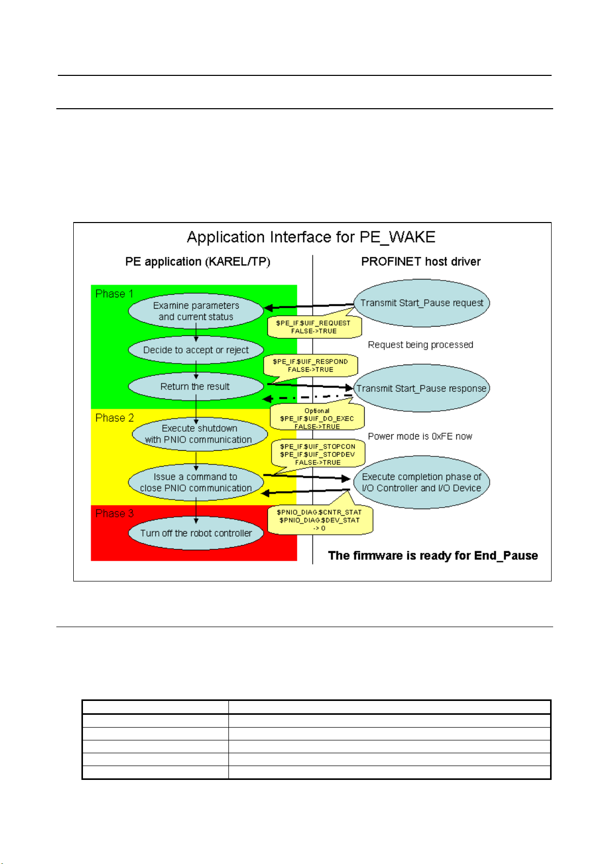
B-82864EN/09 11. PROFIenergy
Name
Usage
$PNPE_IF.$RQ_ID
Service_Request_ID, 1
$PNPE_IF.$RQ_REF
Request_Reference, 1 .. 255
$PNPE_IF.$RQ_MOD
Modifier, 0
$PNPE_IF.$RQ_DSI
Structure_ID, 1
$PNPE_IF.$OFF_TIME
Pause_Time (in milliseconds)
11.4.3 PE application for sleep mode (PE_WAKE)
The following procedure must be executed to activate sleep mode.
1. Start_Pause sequence
2. Closing I/O Device and I/O Controller.
3. Turning off Robot Controller
The Fig. 11.4.3(a) explains the sequence of the procedure. Please note that PE application controls the
sequence and API is located between PE application and PROFINET host driver.
11.4.3.1 Start_Pause sequence
The sequence is initiated when PROFINET host driver receives Start_Pause request from PE controller.
PROFINET host driver delivers the data via API, which sets the following system variables and sets
$PNPE_IF.$UIF_REQUEST = TRUE to notify PE application of reception of PE command.
Fig. 11.4.3 (a) Sequence of sleep mode
Table 11.4.3.1 (a) System variables set b y API
- 76 -
Page 87
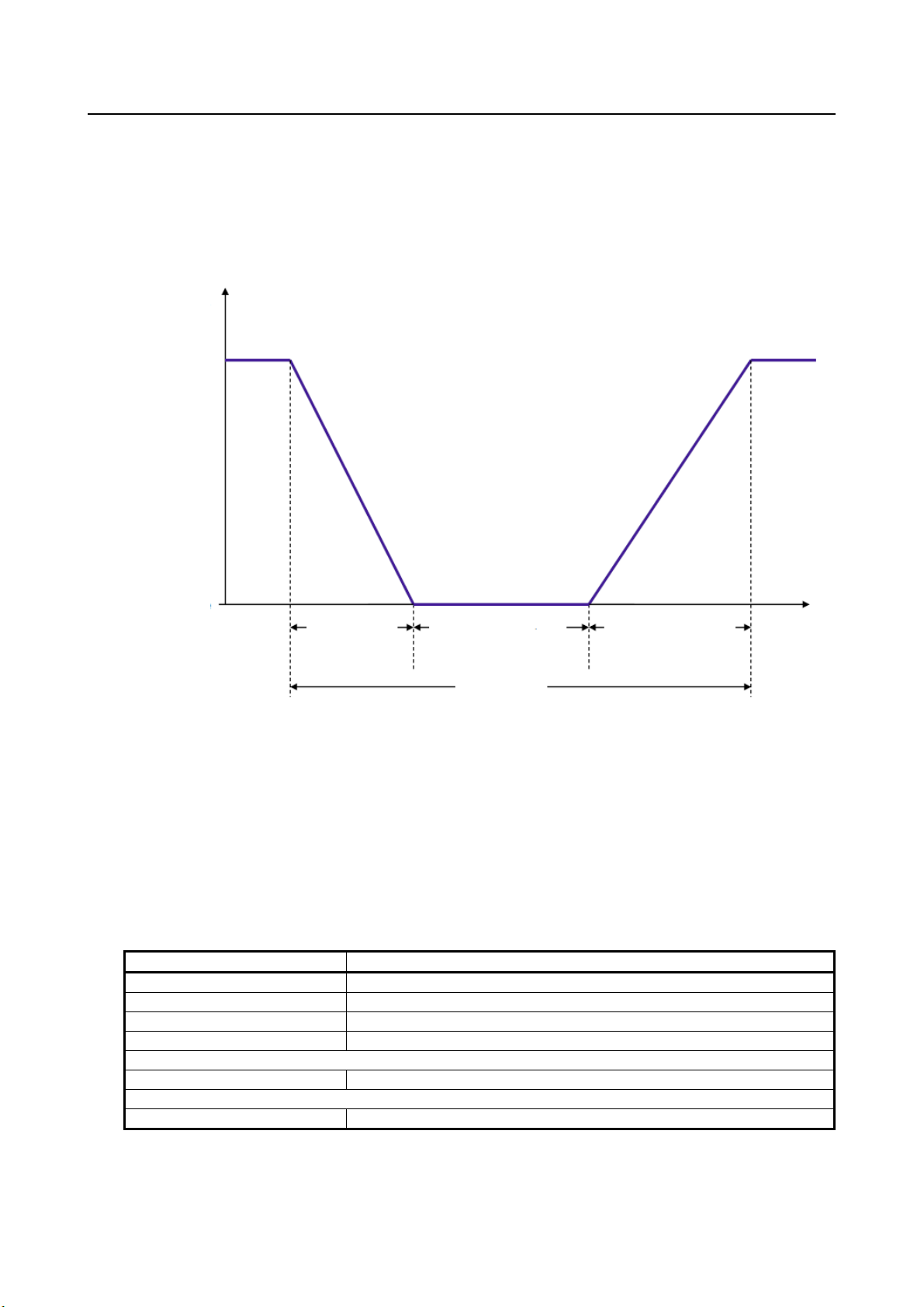
B-82864EN/09 11. PROFIenergy
Name
Usage
$PNPE_IF.$RQ_ID
Service_Request_ID, 1 (unchanged)
$PNPE_IF.$RQ_REF
Request_Reference, 1 .. 255 (unchanged)
$PNPE_IF.$RS_STAT
Status, 1 = w/o failure or 2 = failure
$PNPE_IF.$RS_DSI
Structure_ID, 1 = w/o failure, 255 = failure
(w/o failure)
$PNPE_IF.$ID
PE_MODE_ID, 254 = PE_sleep_mode_WOL
(failure)
$PNPE_IF.$ERROR
Error_Code, 80 = No suitable PE mode available
energy
consumption
PE_ready_to_operate
PE-saving mode
Time_to_Pause
Time_min_length_of_stay
Regular_time_to_operate
Pause_Time
PE application is supposed to set $PNPE_IF.$UIF_REQUEST = FALSE and decides whether transition
to 0xFE is accepted or rejected by
• If Pause_Time is enough, or not.
• If the robot is ready to pause (can go to pause), or under operation (cannot go to pause).
• Transition to 0xFE has already been on the way.
• Any other user specific conditions.
Fig. 11.4.3.1 (a) Energy consumption during Pause_Time
Device changes from PE energy-saving mode to PE_ready_to_operate if Start_Pause command with a
Pause_time less than the smallest supported one and therefore no suitable PE energy-saving modes are
available (Device returns positive response).
PE application sets the following system variables. If transition is accepted, the system variables in (w/o
failure) follow. If transition is rejected, the system variables in (failure) follow. Then PE application sets
$PNPE_IF.$UIF_RESPOND = TRUE. In case PE application can’t respond, PE application should set
$PNPE_IF.$UIF_TIMEOUT = TRUE.
Table 11.4.3.1 (b) System variables set by PE application
API delivers these data to PROFINET host driver. PE controller is supposed to try reading out the result
of Start_Pause, and these data are provided.
- 77 -
Page 88

B-82864EN/09 11. PROFIenergy
I/O Device
I/O Controller
Name
Usage
Enabled
Disabled
$PNPE_IF.$UIF_STOPDEV
Close request for I/O Device.
and I/O Controller.
Name
Usage
$PNIO_DIAG.$CNTR_STAT
Status of I/O Controller, 0 = not-started or closed
$PNIO_DIAG.$DEV_STAT
Status of I/O Device, 0 = not-started or closed
Name
Usage
$PNG2_DIAG.$CNTR_STAT
Status of I/O Controller, 0 = not-started or closed
$PNG2_DIAG.$DEV_STAT
Status of I/O Device, 0 = not-started or closed
Name
Usage
$PNFB_DIAG.$CNTR_STAT
Status of I/O Controller, 0 = not-started or closed
$PNFB_DIAG.$DEV_STAT
Status of I/O Device, 0 = not-started or closed
PROFINET host driver notifies PE application of the completion of reading out of the successful result
($PNPE_IF.$RS_STAT = 1) by setting $PNPE_IF.$UIF_DO_EXEC = TRUE. The use of the flag is
optional. The completion of reading out is one of the necessary condition for CP16XX firmware to go
into sleep mode. It may be worth waiting $PNPE_IF.$UIF_DO_EXEC = TRUE before proceeding to
next phase.
11.4.3.2 Closing I/O device and I/O controller
PE application is supposed to close PROFINET I/O. The following system variables are used to close I/O
Controller and I/O Device.
Table 11.4.3.2 (a) System variables for closing I/O device and I/O controller
Enabled Enabled $PNPE_IF.$UIF_STOPCON Close request for both I/O Device
PE application monitors the status of I/O Controller and I/O Device.
Please use following system variables, if you ordered PROFINET I/O (A05B-2600-J930).
Please use following system variables, if you ordered PROFINET I-device (A05B-2600-J709).
Please use following system variables, if you ordered PROFINET FANUC board (A05B-2600-S523).
11.4.3.3 Turning off Robot Controller
After both I/O Controller and I/O Device are closed, PE application can turn off the robot controller by
OPDO[x]. The PROFINET board’s firmware is now running in sleep mode and waiting for End_Pause
(CP16XX power is supplied by external power). The robot controller turns on when the PROFINET
board receives End_Pause.
- 78 -
Page 89

B-82864EN/09 11. PROFIenergy
Member
Type
Usage
$NAME
STRING
Name
$ENABLE
BOOLEAN
Enable/Disable
$ID
UBYTE
PE_Mode_ID
$ATR
UBYTE
PE_Mode_Attribute
$MIN_OFF
ULONG
Time_min_Pause
Minimum pause time (in milisecond) for this PE energy-saving mode
Expected time (in milisecond) to switch to this PE energy-saving mode
$T_TO_ON
ULONG
Regular_time_to_operate
mode will be regularly terminated.
Time of minimum stay (in milisecond) in this mode.
$T_MAX_OFF
ULONG
Time_max_length_of_stay
Time of maximum stay (in milisecond) in this mode.
Power consumption (in kWh) in the PE-saving mode.
$EN_TO_ON
REAL
Energy_Consumption_to_operate
PE_ready_to_operate.
mode.
PE commands
Service Request_ID
Modifier
Data_Struct_Identifier
(positive response)
Start_Pause
1 0 1
Start_Pause with time response
1 1 2
End_Pause
2 0 1
(List_Energy_Saving_Modes)
Query_Modes (Get_Mode)
3 2 2
PEM_Status
4 0 1
PEM_Status with CTTO
4 1 2
PE_Identify
5 0 1
Query_Version
6 0 1
11.4.4 PE application for power management
PE application needs to know if transition to power saving mode is possible or not. PE application may
reject Start_Pause when robot is in operation. PROFIenergy profile gives PE mode ID to these status,
0xFF (PE_ready_to_operate) and 0xF0 (PE_operate). The transition between the two power modes is
completely up to PE application.
Power saving modes other than 0xFF (PE_ready_to_operate), 0xFE (PE_sleep_mode_WOL) and 0xF0
(PE_operation) are optional, and usage is up to PE application.
The following system variables are prepared for power saving modes. Array of system variable $PNPE
Table 11.4.4 (a) System variables for power saving modes
$T_TO_OFF ULONG Time_to_Pause
The time to reach PE_ready_to_operate (in milisecond) if the energy-saving
$T_MIN_OFF ULONG Time_min_length_of_stay
$EN REAL Mode_Power_Consumption
Energy consumption (in kWh) from the PE-saving mode to
$EN_TO_OFF REAL Energy_Consumption_to_pause
Energy consumption (in kWh) from PE_ready_to_operate to the PE-saving
11.4.5 Other PE commands
Following commands are mandatory for PE entity class 1. The PE application is supposed to respond to
all of these commands.
Table 11.4.5 (a) PE comands
Query_Modes
3 1 1
- 79 -
Page 90

B-82864EN/09 11. PROFIenergy
Name
Usage
$PNPE_IF.$RQ_ID
Service_Request_ID, 1
$PNPE_IF.$RQ_REF
Request_Reference, 1 .. 255
$PNPE_IF.$RQ_MOD
Modifier, 0
$PNPE_IF.$RQ_DSI
Structure_ID, 1
$PNPE_IF.$OFF_TIME
Pause_Time (in milliseconds)
General PE command sequence is like the following:
PE controller may send PE commands at any time when PROFINET I/O communication is running.
PROFINET host driver delivers the data via API, which sets a set of system variables (explained in the
following explanation of each PE command) and sets $PNPE_IF.$UIF_REQUEST = TRUE to notify PE
application of reception of PE command.
PE application is supposed to set $PNPE_IF.$UIF_REQUEST = FALSE and reacts the PE command
according to the system variables.
PE application is supposed to return the reply of the PE command by setting a set of system variables
(explained in the following explanation of each PE command), and sets $PNPE_IF.$UIF_RESPOND =
TRUE. In case PE application can’t respond, PE application should set $PNPE_IF.$UIF_TIMEOUT =
TRUE.
API delivers these data to PROFINET host driver. PE controller is supposed to try reading out the reply
as a result of the PE command.
Please see also 11.4.1 for the data type of each system variables. There are integer values as duration of
time. If the duration of time is infinite, the value –1 shall be used. There are real values as energy
consumption.
11.4.5.1 Start_Pause
Start_Pause may be used for starting sleep mode. Please refer to Subsection 11.4.3 for the details.
Start_Pause may be used for transition to other power-saving modes. The latter case is explained here.
The following system variables are set by the reception of Start_Pause.
Table 11.4.5.1 (a) System variables set b y API
PE application is supposed to set $PNPE_IF.$UIF_REQUEST = FALSE and decides whether transition
to 0xFE is accepted or rejected by
• If Pause_Time is enough, or not.
• If the robot is ready to pause (can go to pause), or under operation (cannot go to pause).
• Transition to 0xFE has already been on the way.
• Any other user specific conditions.
PE application sets the following system variables as a reply. If transition is accepted, the system
variables in (w/o failure) follow. If transition is rejected, the system variables in (failure) follow.
- 80 -
Page 91

B-82864EN/09 11. PROFIenergy
Name
Usage
$PNPE_IF.$RQ_ID
Service_Request_ID, 1 (unchanged)
$PNPE_IF.$RQ_REF
Request_Reference, 1 .. 255 (unchanged)
$PNPE_IF.$RS_STAT
Status, 1 = w/o failure or 2 = failure
$PNPE_IF.$RS_DSI
Structure_ID, 1=w/o failure, 255=failure
(w/o failure)
$PNPE_IF.$ID
PE_MODE_ID
(failure)
$PNPE_IF.$ERROR
Error_Code, 80=No suitable PE mode available
Name
Usage
$PNPE_IF.$RQ_ID
Service_Request_ID, 1
$PNPE_IF.$RQ_REF
Request_Reference, 1 .. 255
$PNPE_IF.$RQ_MOD
Modifier, 1
$PNPE_IF.$RQ_DSI
Structure_ID, 1
$PNPE_IF.$OFF_TIME
Pause_Time (in milliseconds)
Name
Usage
$PNPE_IF.$RQ_ID
Service_Request_ID, 1 (unchanged)
$PNPE_IF.$RQ_REF
Request_Reference, 1 .. 255 (unchanged)
$PNPE_IF.$RS_STAT
Status, 1 = w/o failure or 2 = failure
$PNPE_IF.$RS_DSI
Structure_ID, 2 = w/o failure, 255 = failure
(w/o failure)
$PNPE_IF.$ID
PE_MODE_ID
$PNPE_IF.$C_T_TO_DST
Current_time_to_destination (in milliseconds)
$PNPE_IF.$T_TO_ON
Regular_time_to_operate (in milliseconds)
$PNPE_IF.$T_MIN_OFF
Time_min_length_of_stay (in milliseconds)
(failure)
$PNPE_IF.$ERROR
Error_Code, 80 = No suitable PE mode available
Table 11.4.5.1 (b) System variables set by PE application
PROFINET host driver notifies PE application of the completion of reading out of the successful result
($PNPE_IF.$RS_STAT = 1) by setting $PNPE_IF.$UIF_DO_EXEC = TRUE. The use of the flag is
optional. The completion of reading out is one of the necessary condition for CP16XX firmware to go
into sleep mode. It may be worth waiting $PNPE_IF.$UIF_DO_EXEC = TRUE.
Then PE application is supposed to do the required process for transition to the power-saving mode,
which is up to the power-saving application.
11.4.5.2 Start_Pause with time response
Start_Pause with time response is an extension of Start_Pause but it uses different Modifier in request and
Data_Struct_Identifier in positive response. Please refer to Subsection 11.4.3 if it is used for starting sleep
mode. It may be used for transition to other power-saving modes, and this case is explained here.
Start_Pause with time response is the same as Start_Pause except for the data values. Please refer to
11.4.5.1 for the detailed sequence. Only the data values are explained here.
The following system variables are set by the reception of Start_Pause.
Table 11.4.5.2 (a) System variables set by API
PE application sets the following system variables as a reply. If transition is accepted, the system
variables in (w/o failure) follow. If transition is rejected, the system variables in (failure) follow.
Table 11.4.5.2 (b) System variables set by PE application
- 81 -
Page 92

B-82864EN/09 11. PROFIenergy
Name
Usage
$PNPE_IF.$RQ_ID
Service_Request_ID, 2
$PNPE_IF.$RQ_REF
Request_Reference, 1 .. 255
$PNPE_IF.$RQ_MOD
Modifier, 0
$PNPE_IF.$RQ_DSI
Structure_ID, 0
Name
Usage
$PNPE_IF.$RQ_ID
Service_Request_ID, 2 (unchanged)
$PNPE_IF.$RQ_REF
Request_Reference, 1 .. 255 (unchanged)
$PNPE_IF.$RS_STAT
Status, 1 = w/o failure
$PNPE_IF.$RS_DSI
Structure_ID, 1 = w/o failure
(w/o failure)
$PNPE_IF.$C_T_TO_ON
Current_time_to_operate (in milliseconds)
Name
Usage
$PNPE_IF.$RQ_ID
Service_Request_ID, 3
$PNPE_IF.$RQ_REF
Request_Reference, 1 .. 255
$PNPE_IF.$RQ_MOD
Modifier, 1
$PNPE_IF.$RQ_DSI
Structure_ID, 0
Name
Usage
$PNPE_IF.$RQ_ID
Service_Request_ID, 3 (unchanged)
$PNPE_IF.$RQ_REF
Request_Reference, 1 .. 255 (unchanged)
$PNPE_IF.$RS_STAT
Status, 1 = w/o failure
$PNPE_IF.$RS_DSI
Structure_ID, 1 = w/o failure
(w/o failure)
PE_Mode_ID in this array.
11.4.5.3 End_Pause
End_Pause is used for bringing the controller back from a power-saving mode to PE_ready_to_operate.
According to the PROFIEnergy profile, “The command shall always be accepted with a response without
failure by the PE Entity. Even if the time of minimum stay in an energy-saving mode is still running”.
The following system variables are set by the reception of End_Pause.
Table 11.4.5.3 (a) System variables set b y API
PE application sets the following system variables as a reply
Table 11.4.5.3 (b) System variables set b y PE application
11.4.5.4 Query_Modes (List_Energy_Saving_Modes)
This PE command is used for reading out the list of energy-saving modes.
The following system variables are set by the reception of Query_Modes.
Table 11.4.5.4 (a) System variables set by API
PE application sets the following system variables as a reply.
Table 11.4.5.4 (b) System variables set by PE application
$PNPE_MODE[x] PE_Mode_ID of each energy-saving modes, 1..255. The value should be
filled from $PNPE_MODE[1], and the value = 0 means there is no more
- 82 -
Page 93

B-82864EN/09 11. PROFIenergy
Name
Usage
$PNPE_IF.$RQ_ID
Service_Request_ID, 3
$PNPE_IF.$RQ_REF
Request_Reference, 1 .. 255
$PNPE_IF.$RQ_MOD
Modifier, 2
$PNPE_IF.$RQ_DSI
Structure_ID, 1
$PNPE_IF.$GET_ID
PE_Mode_ID to be read out, 1..255
Name
Usage
$PNPE_IF.$RQ_ID
Service_Request_ID, 3 (unchanged)
$PNPE_IF.$RQ_REF
Request_Reference, 1 .. 255 (unchanged)
$PNPE_IF.$RS_STAT
Status, 1 = w/o failure, 2 = failure
$PNPE_IF.$RS_DSI
Structure_ID, 2 = w/o failure, 255 = failure
(w/o failure)
$PNPE_IF.$GET_ID
PE_Mode_ID to be read out, 1..255 (unchanged)
$PNPE_IF.$ATR
PE_Mode_Attribute
$PNPE_IF.$MIN_OFF
Time_min_Pause (in milliseconds)
$PNPE_IF.$T_TO_OFF
Time_min_Pause (in milliseconds)
$PNPE_IF.$T_TO_ON
Time_to_Pause (in milliseconds)
$PNPE_IF.$T_MIN_OFF
Time_min_length_of_stay (in milliseconds)
$PNPE_IF.$T_MAX_OFF
Time_max_length_of_stay (in milliseconds)
$PNPE_IF.$EN
Mode_Power_Consumption (real value in kWh)
$PNPE_IF.$EN_TO_OFF
Energy_Consumption_to_pause (real value in kWh)
$PNPE_IF.$EN_TO_ON
Energy_Consumption_to_operate (real value in kWh)
(failure)
$PNPE_IF.$ERROR
Error_Code, 82 Impermissble PE_Mode_ID
Name
Usage
$PNPE_IF.$RQ_ID
Service_Request_ID, 4
$PNPE_IF.$RQ_REF
Request_Reference, 1 .. 255
$PNPE_IF.$RQ_MOD
Modifier, 0
$PNPE_IF.$RQ_DSI
Structure_ID, 0
11.4.5.5 Query_Modes (Get_Mode)
This PE command is used for reading out the detail of an energy-saving mode. All PE_Mode_ID in
Query_Modes (List_Energy_Saving_Modes) shall be supported by this command.
The following system variables are set by the reception of Query_Modes.
Table 11.4.5.5 (a) System variables set b y API
PE application sets the following system variables as a reply. In case of PE_Mode_ID doesn’t match any
existing PE_Mode_ID, the values (failure) are used.
Table 11.4.5.5 (b) System variables set by PE application
11.4.5.6 PEM_Status
The command is used to monitor the current status of PE transition or activate PE modes.
The following system variables are set by the reception of PEM_Status.
Table 11.4.5.6 (a) System variables set b y API
- 83 -
Page 94

B-82864EN/09 11. PROFIenergy
Name
Usage
$PNPE_IF.$RQ_ID
Service_Request_ID, 4 (unchanged)
$PNPE_IF.$RQ_REF
Request_Reference, 1 .. 255 (unchanged)
$PNPE_IF.$RS_STAT
Status, 1 = w/o failure
$PNPE_IF.$RS_DSI
Structure_ID, 1 = w/o failure
(w/o failure)
$PNPE_IF.$ID_SRC
PE_Mode_ID_Source
$PNPE_IF.$ID_DST
PE_Mode_ID_Destination
$PNPE_IF.$C_T_TO_ON
Current_time_to_operate (in milliseconds)
$PNPE_IF.$C_T_TO_DST
Current_time_to_destination (in milliseconds)
$PNPE_IF.$EN
Mode_Power_Consumption (real value in kWh)
$PNPE_IF.$EN_TO_OFF
Energy_Consumption_to_pause (real value in kWh)
$PNPE_IF.$EN_TO_ON
Energy_Consumption_to_operate (real value in kWh)
Name
Usage
$PNPE_IF.$RQ_ID
Service_Request_ID, 4
$PNPE_IF.$RQ_REF
Request_Reference, 1 .. 255
$PNPE_IF.$RQ_MOD
Modifier, 1
$PNPE_IF.$RQ_DSI
Structure_ID, 0
Name
Usage
$PNPE_IF.$RQ_ID
Service_Request_ID, 4 (unchanged)
$PNPE_IF.$RQ_REF
Request_Reference, 1 .. 255 (unchanged)
$PNPE_IF.$RS_STAT
Status, 1 = w/o failure
$PNPE_IF.$RS_DSI
Structure_ID, 2 = w/o failure
(w/o failure)
$PNPE_IF.$ID_SRC
PE_Mode_ID_Source
$PNPE_IF.$ID_DST
PE_Mode_ID_Destination
$PNPE_IF.$T_TO_ON
Regular_time_to_operate (in milliseconds)
$PNPE_IF.$C_T_TO_ON
Current_time_to_operate (in milliseconds)
$PNPE_IF.$C_T_TO_DST
Current_time_to_destination (in milliseconds)
$PNPE_IF.$EN
Mode_Power_Consumption (real value in kWh)
$PNPE_IF.$EN_TO_OFF
Energy_Consumption_to_pause (real value in kWh)
$PNPE_IF.$EN_TO_ON
Energy_Consumption_to_operate (real value in kWh)
PE application sets the following system variables as a reply.
Table 11.4.5.6 (b) System variables set by PE application
11.4.5.7 PEM_Status with CTTO
PEM_Status with CTTO is the same as PEM_State except for the data values.
The following system variables are set by the reception of PEM_Status.
Table 11.4.5.7 (a) System variables set b y API
PE application sets the following system variables as a reply.
Table 11.4.5.7 (b) System variables set by PE application
- 84 -
Page 95

B-82864EN/09 11. PROFIenergy
Name
Usage
$PNPE_IF.$RQ_ID
Service_Request_ID, 5
$PNPE_IF.$RQ_REF
Request_Reference, 1 .. 255
$PNPE_IF.$RQ_MOD
Modifier, 0
$PNPE_IF.$RQ_DSI
Structure_ID, 0
Name
Usage
$PNPE_IF.$RQ_ID
Service_Request_ID, 5 (unchanged)
$PNPE_IF.$RQ_REF
Request_Reference, 1 .. 255 (unchanged)
$PNPE_IF.$RS_STAT
Status, 1 = w/o failure
$PNPE_IF.$RS_DSI
Structure_ID, 1 = w/o failure
(w/o failure)
$PNPE_SERV[x]
Service_Request_ID of supported service. The value should be filled from
array.
Name
Usage
$PNPE_IF.$RQ_ID
Service_Request_ID, 6
$PNPE_IF.$RQ_REF
Request_Reference, 1 .. 255
$PNPE_IF.$RQ_MOD
Modifier, 0
$PNPE_IF.$RQ_DSI
Structure_ID, 0
Name
Usage
$PNPE_IF.$RQ_ID
Service_Request_ID, 6 (unchanged)
$PNPE_IF.$RQ_REF
Request_Reference, 1 .. 255 (unchanged)
$PNPE_IF.$RS_STAT
Status, 1 = w/o failure
$PNPE_IF.$RS_DSI
Structure_ID, 1 = w/o failure
(w/o failure)
$PNPE_IF.$MAJOR_VER
major_version_number, this should be 1.
$PNPE_IF.$MINOR_VER
minor_version_numer, this should be 1.
11.4.5.8 PE_Identify
This PE command provides the list of supported services.
The following system variables are set by the reception of PE_Identify.
Table 11.4.5.8 (a) System variables set by API
PE application sets the following system variables as a reply.
Table 11.4.5.8 (b) System variables set by PE application
$PNPE_SERV[1], and the value = 0 means there is no more services in this
11.4.5.9 Query_Version
This PE command provides the implemented version of the PROFIenergy profile.
The following system variables are set by the reception of Query_Version.
Table 11.4.5.9 (a) System variables set by API
PE application sets the following system variables as a reply.
Table 11.4.5.9 (b) System variables set by PE application
- 85 -
Page 96

B-82864EN/09 11. PROFIenergy
which needs to program by the end user himself.
11.5 PE Controller
PROFINET FANUC board (A05B-2600-S523) does not support this function.
If you want to use this function, please order PROFINET I/O (A05B-2600-J930) or PROFINET I-device
(A05B-2600-J709).
After that, there is an explanation about system variables, but if you ordered PROFINET I-device (A05B2600-J709), please replace $PNIO with $PNG2.
PE controller function uses the interface of reading/writing PNIO record in I/O Controller function, which
is not specific to PROFIenergy. The interface is disabled by default, and should be enabled by setting the
bit2 (0x00000004) of $PNIO_CFG.$CUSTOM to 1.
WARNING
The PNPE controller functionality is totally dissociated from PNPE
device functionality. (Fig. 11.5(a) ) In case that the switching among the different
power saving levels on Robot controller (as PNPE device) does impact also on
some/all of its underlying devices (i.e.: Robot controller is PNPE device towards
upper line controller; and PNPE controller towards lower robot periphery). Then,
how lower robot periphery devices to be controlled, it is up to the user application
Fig. 11.5 (a) Example of network configuration
Following is the technical description of the ReadWriteRecord function, as implemented in the KAREL
routine PNIO_REC:
To use this function, the bit2 (0x00000004) of $PNIO_CFG.$CUSTOM must be 1, and the cycle power is
required to activate the change.
The max. data size of record is as follows according to the specification of CP16xx.
Read : Up to 4096 bytes
Write : Up to 512 bytes
- 86 -
Page 97

B-82864EN/09 11. PROFIenergy
The following KAREL variables of “PNIO_REC” are used as interface to any user KAREL program.
The user KAREL program sets $TYPE, $ADDRTYPE, $IOTYPE, $ADDRESS and $INDEX for a
read job, and sets $REQ = 1 ($ACK must be 0) to request the read job. Then $BUSY gets to 1. When
the read job finishes, $BUSY gets to 0, and $ACK gets to 1. If the read job is successful,
$ERR_CODE is 0, and $LENGTH and $DATA is available. $ERR_STAT is usually filled with 0.
If the read job fails, $ERR_CODE is not 0, and it indicates the cause of failure.
The user KAREL program sets $TYPE, $ADDRTYPE, $IOTYPE, $ADDRESS, $INDEX,
$W_LENGTH, and $W_DATA for a write job, and sets $REQ=1 ($ACK must be 0) to request the
write job. Then $BUSY gets to 1. When the write job finishes, $BUSY gets to 0, and $ACK gets to
1. If the write job is successful, $ERR_CODE is 0, and $ERR_STAT is usually filled with 0. If the
read job fails, $ERR_CODE is not 0, and it indicates the cause of failure.
$ACK must be set to 0 before initiating the next job request.
The user KAREL program must waits until the former read/write job finishes.
$STATION, $SLOT, $SUBSLOT can be used alternatively instead of using $ADDRTYPE,
$IOTYPE, and $ADDRESS to address. This can be selected by a setting the bit3(0x00000008) of
$PNIO_CFG.$CUSTOM to 1. The cycle power is required to activate the change.
- 87 -
Page 98

B-82864EN/09 11. PROFIenergy
Name
Meaning/Function
$TYPE
The user KAREL program sets the operation type here.
1: Read, 2: Write.
$ADDRTYPE
The user KAREL program sets the address type of target device here. This should be
PNIO_ADDR_GEO = 1
$IOTYPE
The user KAREL program sets the I/O type of target device here. Use PNIO_IO_IN for
PNIO_IO_OUT = 1,
$ADDRESS
(standard)
The user KAREL program sets the address type of target device here.
$STATION
(alternative)
The user KAREL program sets the station number of the target device here.
$SLOT
(alternative)
The user KAREL program sets the slot number of the target device here.
$SUBSLOT
(alternative)
The user KAREL program sets the subslot number of the target device here.
$INDEX
The user KAREL program sets the record index here.
$W_LENGTH
The user KAREL program sets the length of data to be written here. It is used when
$TYPE=2.
$W_DATA
The user KAREL program sets the data to be written here. It is used when $TYPE = 2.
$REQ
The user KAREL program sets $REQ = 1 to request PROFINET function to read/write the
record specified by the KAREL variables above. $REQ returns to 0 automatically.
$BUSY
PROFINET function sets $BUSY = 1 while handling the requested read/write job. $BUSY
returns to 0 automatically when the job finishes or fails.
$ACK
PROFINET function sets $ACK = 1 after the read/write job finishes or fails. The result is
must set $ACK = 0 after reading the result. $ACK must be 0 before setting $REQ = 1.
$ERR_CODE
PROFINET function sets $ERR_CODE to show if error occurs during the read/write job.
0d11 = 0b1011; 0d5 = 0b0101 >>> 0000 0000 1011 0101 = 0xB5 = 0d181 >>> “state conflict”
$ERR_STAT
PROFINET function copies the error code from CP16XX.
$LENGTH
PROFINET function sets the length of the data read from the specified record when the read
job is successful.
$DATA
PROFINET function sets the data read from the specified record when the read job is
successful. When the user KAREL program sets $ACK to 0, $DATA is deleted.
Table 11.5 (a) KAREL variables
(standard)
(standard)
PNIO_ADDR_LOG.
PNIO_ADDR_LOG = 0,
diagnostic address.
PNIO_IO_IN = 0,
informed by $ERR_CODE, $ERR_STAT, $LENGTH and $DATA. The user KAREL program
$ERR_CODE = 0 if the read/write job is successful.
$ERR_CODE < 0x8000, error is reported by PROFINET (the host driver, or CP1616). Please
see pnioerrx.h in the CP1616 development kit for the meaning of the error code.
Otherwise, PROFINET function reports the following error.
0x8001: $TYPE is wrong
0x8002: $W_LENGTH = 0 for the write job.
0x8003: Internal system error.
0x8004: Unexpected job response.
0x8005: Internal system error.
0x8006: Specified address/device is not found.
PS: There is dedicated error handling for the PESAP (section 7.5)
0d10 = 0b1010; 0d7 = 0b0111 >>> 0000 0000 1010 0111 = 0xA7 = 0d167 >>> “busy”
0d11 = 0b1011; 0d1 = 0b0001 >>> 0000 0000 1011 0001 = 0xB1 = 0d177 >>> “write length
error”
- 88 -
Page 99

APPENDIX
Page 100

 Loading...