

Page 1

GE Fanuc Automation
Computer Numerical Control Products
Series 16 i / 160 i–LA
Parameter Manual
GFZ-63200EN/02 July 2000
Page 2

Warnings, Cautions, and Notes
as Used in this Publication
Warning notices are used in this publication to emphasize that hazardous voltages, currents,
temperatures, or other conditions that could cause personal injury exist in this equipment or may
be associated with its use.
In situations where inattention could cause either personal injury or damage to equipment, a
Warning notice is used.
Caution notices are used where equipment might be damaged if care is not taken.
GFL-001
Warning
Caution
Note
Notes merely call attention to information that is especially significant to understanding and
operating the equipment.
This document is based on information available at the time of its publication. While efforts
have been made to be accurate, the information contained herein does not purport to cover all
details or variations in hardware or software, nor to provide for every possible contingency in
connection with installation, operation, or maintenance. Features may be described herein which
are not present in all hardware and software systems. GE Fanuc Automation assumes no
obligation of notice to holders of this document with respect to changes subsequently made.
GE Fanuc Automation makes no representation or warranty, expressed, implied, or statutory
with respect to, and assumes no responsibility for the accuracy, completeness, sufficiency, or
usefulness of the information contained herein. No warranties of merchantability or fitness for
purpose shall apply.
©Copyright 2000 GE Fanuc Automation North America, Inc.
All Rights Reserved.
Page 3
B–63200EN/02
PREFACE
PREFACE
Applicable Models
Related Manuals
The mode covered by this manual, and their abbreviations are :
Product Name Abbreviations
FANUC Series 16i–LA 16i–LA
FANUC Series 160i–LA 160i–LA
The table below lists manuals related to Series 16i–LA and 160i–LA. In
the table, this manual is marked with an asterisk (*).
Table 1 List of related manuals for Series 16i/160i–LA
Manual name
FANUC Series 16i/18i/21i/160i/180i/210i–MODEL A
DESCRIPTIONS
FANUC Series 16i/18i/21i/20i/160i/180i/210i–MODEL A
CONNECTION MANUAL (HARDWARE)
FANUC Series 16i/18i/21i/20i/160i/180i/210i–MODEL A
CONNECTION MANUAL (FUNCTION)
FANUC Series 16i/18i/160i/180i–MODEL A
P ARAMETER MANUAL
FANUC Series 16i/160i–LA DESCRIPTIONS B–63192EN
FANUC Series 16i/160i–LA CONNECTION MANUAL B–63193EN
FANUC Series 16i/160i–LA OPERATOR’S MANUAL B–63194EN
FANUC Series 16i/160i–LA MAINTENANCE MANUAL B–63195EN
FANUC Series 16i/160i–LA PARAMETER MANUAL B–63200EN
FANUC Series 16/18/20/21 PROGRAMMING MANUAL
(Macro Compiler/Macro Executer)
FAPT MACRO COMPILER PROGRAMMING MANUAL B–66102E
Specification
Number
B–63002EN
B–63003EN
B–63003EN–1
B–63010EN
B–61803E–1
p–1
Page 4

B–63200EN/02
Table of Contents
PREFACE p–1. . . . . . . . . . . . . . . . . . . . . . . . . . . . . . . . . . . . . . . . . . . . . . . . . . . . . . . . . . . . . . . .
1. DISPLAYING PARAMETERS 1. . . . . . . . . . . . . . . . . . . . . . . . . . . . . . . . . . . . . . . . . . . .
2. SETTING PARAMETERS FROM MDI 2. . . . . . . . . . . . . . . . . . . . . . . . . . . . . . . . . . . .
3. INPUTTING AND OUTPUTTING PARAMETERS THROUGH
THE READER/PUNCHER INTERF ACE 4. . . . . . . . . . . . . . . . . . . . . . . . . . . . . . . . . . .
3.1 OUTPUTTING PARAMETERS THROUGH THE READER/PUNCHER INTERFACE 5. . . . . . . .
3.2 INPUTTING PARAMETERS THROUGH THE READER/PUNCHER INTERFACE 6. . . . . . . . . .
4. DESCRIPTION OF PARAMETERS 7. . . . . . . . . . . . . . . . . . . . . . . . . . . . . . . . . . . . . . .
4.1 SETTINGS FOR ENABLING/DISABLING FUNCTIONS 8. . . . . . . . . . . . . . . . . . . . . . . . . . . . . . .
4.2 DISCHARGE TUBE SELECTION 14. . . . . . . . . . . . . . . . . . . . . . . . . . . . . . . . . . . . . . . . . . . . . . . . . .
4.3 CONTOURING CONDITIONS 15. . . . . . . . . . . . . . . . . . . . . . . . . . . . . . . . . . . . . . . . . . . . . . . . . . . . .
4.4 EDGE MACHINING CONDITIONS 16. . . . . . . . . . . . . . . . . . . . . . . . . . . . . . . . . . . . . . . . . . . . . . . . .
4.5 PIERCING CONDITIONS 18. . . . . . . . . . . . . . . . . . . . . . . . . . . . . . . . . . . . . . . . . . . . . . . . . . . . . . . . .
4.6 POWER CONTROL 20. . . . . . . . . . . . . . . . . . . . . . . . . . . . . . . . . . . . . . . . . . . . . . . . . . . . . . . . . . . . . .
4.7 SETTINGS RELATED TO ASSIST GAS PRESSURE AND TIME 22. . . . . . . . . . . . . . . . . . . . . . . .
4.8 LASER MAINTENANCE/INSPECTION TIME DISPLAY FUNCTION 25. . . . . . . . . . . . . . . . . . . .
4.9 PARAMETERS RELATED TO OSCILLATOR CONTROL 27. . . . . . . . . . . . . . . . . . . . . . . . . . . . . .
4.10 PARAMETERS RELATED TO DISCHARGE 31. . . . . . . . . . . . . . . . . . . . . . . . . . . . . . . . . . . . . . . . .
4.11 PARAMETERS RELATED TO GAS PRESSURE CONTROL (1) 32. . . . . . . . . . . . . . . . . . . . . . . . .
4.12 HIGHLY REFLECTIVE MATERIAL ALARMS 35. . . . . . . . . . . . . . . . . . . . . . . . . . . . . . . . . . . . . . .
4.13 LASER POWER/VOLTAGE DECREASE 36. . . . . . . . . . . . . . . . . . . . . . . . . . . . . . . . . . . . . . . . . . . .
4.14 POWER TABLE SETTINGS 37. . . . . . . . . . . . . . . . . . . . . . . . . . . . . . . . . . . . . . . . . . . . . . . . . . . . . . .
4.15 AUTOMATIC AGING FUNCTION 39. . . . . . . . . . . . . . . . . . . . . . . . . . . . . . . . . . . . . . . . . . . . . . . . .
4.16 PARAMETERS RELATED TO THE PMC–WINDOW 42. . . . . . . . . . . . . . . . . . . . . . . . . . . . . . . . . .
4.17 POWER CONTROL (2) 43. . . . . . . . . . . . . . . . . . . . . . . . . . . . . . . . . . . . . . . . . . . . . . . . . . . . . . . . . . .
4.18 SETTINGS RELATED TO TRACING (DETECTION) 44. . . . . . . . . . . . . . . . . . . . . . . . . . . . . . . . . .
4.19 SETTING RELATED TO TRACING (DISPLAY) 45. . . . . . . . . . . . . . . . . . . . . . . . . . . . . . . . . . . . . .
4.20 SETTINGS RELATED TO TRACING (INTEGRATION) 46. . . . . . . . . . . . . . . . . . . . . . . . . . . . . . . .
4.21 SETTINGS RELATED TO TRACING (PHASE COMPENSATION) 47. . . . . . . . . . . . . . . . . . . . . . .
4.22 SETTINGS RELATED TO TRACING (DISPLACEMENT) 48. . . . . . . . . . . . . . . . . . . . . . . . . . . . . .
4.23 SETTINGS RELATED TO TRACING (VELOCITY COMMAND) 50. . . . . . . . . . . . . . . . . . . . . . . .
4.24 SETTINGS RELATED TO TRACING (APPROACH) 51. . . . . . . . . . . . . . . . . . . . . . . . . . . . . . . . . . .
4.25 SETTINGS RELATED TO THREE–DIMENSIONAL AXIAL MOVEMENT
(ANGULAR AXIS) 53. . . . . . . . . . . . . . . . . . . . . . . . . . . . . . . . . . . . . . . . . . . . . . . . . . . . . . . . . . . . . .
4.26 PROGRAM RESUMPTION/NEIGHBORING POINT SEARCH 59. . . . . . . . . . . . . . . . . . . . . . . . . .
4.27 TEACHING BOX 61. . . . . . . . . . . . . . . . . . . . . . . . . . . . . . . . . . . . . . . . . . . . . . . . . . . . . . . . . . . . . . . .
4.28 SETTINGS RELATED TO MACHINING RESUMPTION 63. . . . . . . . . . . . . . . . . . . . . . . . . . . . . . .
4.29 CONSTANT OPTICAL PATH CONTROL 67. . . . . . . . . . . . . . . . . . . . . . . . . . . . . . . . . . . . . . . . . . . .
4.30 LASER GAS MIXTURE FUNCTION 69. . . . . . . . . . . . . . . . . . . . . . . . . . . . . . . . . . . . . . . . . . . . . . . .
4.31 THE STEP CONTROL FUNCTION 71. . . . . . . . . . . . . . . . . . . . . . . . . . . . . . . . . . . . . . . . . . . . . . . . .
c–1
Page 5

Table of Contents
B–63200EN/02
4.32 STEP FEED FUNCTION AND RETURN FUNCTION 73. . . . . . . . . . . . . . . . . . . . . . . . . . . . . . . . . .
4.33 PARAMETERS RELATED TO GAS PRESSURE CONTROL (2) 74. . . . . . . . . . . . . . . . . . . . . . . . .
c–2
Page 6
B–63200EN/02
1
1. DISPLAYING PARAMETERS
DISPLAYING PARAMETERS
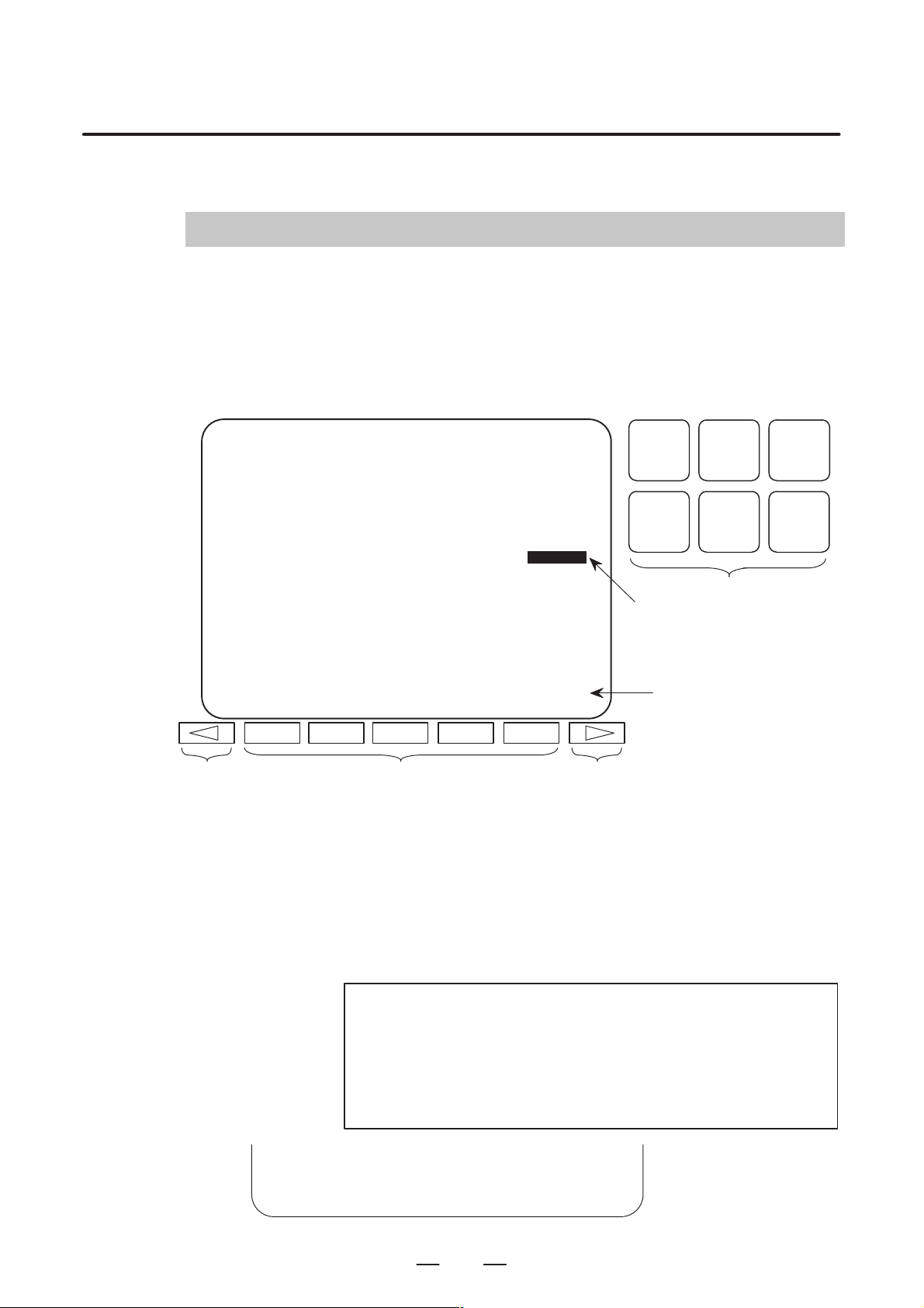
Follow the procedure below to display parameters.
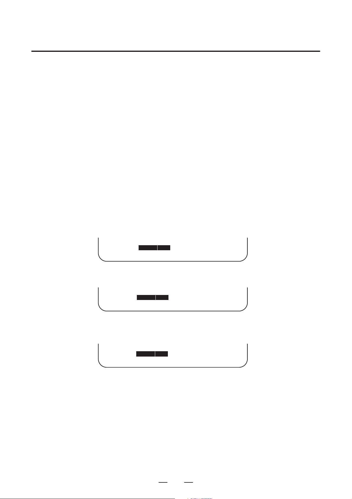
(1) Press the <SYSTEM> function key on the MDI as many times as
required, or alternatively, press the <SYSTEM> function key once,
then the [P ARAM] section display soft key. The parameter screen is
then selected.
PARAMETER (FEEDRATE) O0001 N12345
1401 RDR JZR RF0 LRP RPD
0 0 0 0 0 0 0 0
1402 DLF HFC
0 0 0 0 0 0 0 0
1410 DRY RUN FEEDRATE 10000
1411 INIT.CUTTING F 0
1420 RAPID FEEDRATE X 15000
Y 15000
Z 15000
>
MEM STRT MTN FIN *** 10:02:35
[PARAM] [DGNOS] [ PMC ] [SYSTEM] [(OPRT)]
Return menu key Soft key Continuous menu key
POS PROG
SYSTEM MESSAGE
Cursor
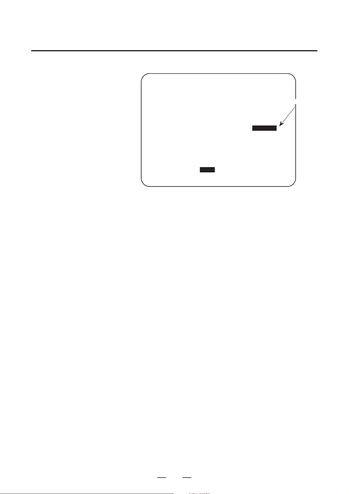
(2) The parameter screen consists of multiple pages. Use step (a) or (b)
to display the page that contains the parameter you want to display.
(a) Use the page select key or the cursor move keys to display the de-
sired page.
(b) Enter the data number of the parameter you want to display from
the keyboard, then press the [NO.SRH] soft key. The parameter
page containing the specified data number appears with the cursor positioned at the data number. (The data is displayed in reverse video.)
OFFSET
SETTING
CUSTOM
GRAPH
Function key
Soft key display
(section select)
NOTE
If key entry is started with the section select soft keys
displayed, they are replaced automatically by operation
select soft keys including [NO.SRH]. Pressing the [(OPRT)]
soft key can also cause the operation select keys to be
displayed.
>1410
MEM STRT MTN FIN *** 10:02:34
[NO.SRH] [ ON:1 ] [ OFF:0 ] [+INPUT] [INPUT ]
1
Data entered from
←
the keyboard
Soft key display
←
(section select)
Page 7

2. SETTING PARAMETERS FROM MDI
SETTING P ARAMETERS FROM MDI
2
Follow the procedure below to set parameters.
(1) Place the CNC in the MDI mode or the emergency stop state.
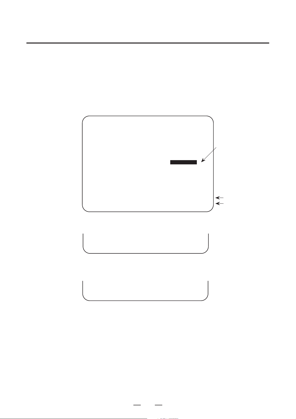
(2) Follow the substeps below to enable writing of parameters.
SETTING (HANDY) O0001 N00010
B–63200EN/02
1. To display the setting screen, press the <OFFSET/SETTING>
function key as many times as required, or alternatively press the
<OFFSET/SETTING> function key once, then the <OFFSET/
SETTING> section select soft key. The first page of the setting
screen appears.
2. Position the cursor on “P ARAMETER WRITE” using the cursor
move keys.
PARAMETER WRITE = (0:DISABLE 1:ENABLE)
TV CHECK = 0 (0:OFF 1:ON)
PUNCH CODE = 0 (0:EIA 1:ISO)
INPUT UNIT = 0 (0:MM 1:INCH)
I/O CHANNEL = 0 (0–3:CHANNEL NO.)
3. Press the [(OPRT)] soft key to display operation select soft keys.
>
MDI STOP *** *** *** 10:03:02
[NO.SRH] [ ON:1 ] [ OFF:0 ] [+INPUT] [INPUT]
4. To set “PARAMETER WRITE=” to 1, press the ON:1 soft key,
or alternatively enter 1 and press the [INPUT] soft key . From now
on, the parameters can be set. At the same time an alarm condition (P/S100 PARAMETER WRITE ENABLE) occurs in the
CNC.
(3) T o display the parameter screen, press the <SYSTEM> function key
as many times as required, or alternatively press the <SYSTEM>
function key once, then the [PARAM] section select soft key.
(See “1. Displaying Parameters.”)
(4) Display the page containing the parameter you want to set, and
position the cursor on the parameter. (See “1. Displaying
Parameters.”)
0
← Soft key display
(section select)
(5) Enter data, then press the [INPUT] soft key. The parameter indicated
by the cursor is set to the entered data.
2
Page 8
B–63200EN/02
2. SETTING PARAMETERS FROM MDI
[Example] 12000 [INPUT]
PARAMETER (FEEDRATE) O0001 N00010
1401 RDR JZR RPD
00000000
1402 JRV
00000000
1410 DRY RUN FEEDRATE
1412 0
1420 RAPID FEEDRATEX 15000
Y 15000
Z 15000
>
MDI STOP *** *** ALM 10:03:10
[NO.SRH] [ ON:1 ] [ OFF:0 ] [+INPUT] [INPUT]
12000
Cursor
Data can be entered continuously for parameters, starting at the selected
parameter, by separating each data item with a semicolon (;).
[Example] Entering 10;20;30;40 and pressing the [INPUT] key assigns values 10,
20, 30, and 40 to parameters in order starting at the parameter indicatedby
the cursor.
(6) Repeat steps (4) and (5) as required.
(7) If parameter setting is complete, set “PARAMETER WRITE=” to 0
on the setting screen to disable further parameter setting.
(8) Reset the NC to release the alarm condition (P/S100).
If an alarm condition (P/S000 PLEASE TURN OFF POWER) occurs
in the NC, turn it off before continuing operation.
3
Page 9

3. INPUTTING AND OUTPUTTING PARAMETERS THROUGH
THE READER/PUNCHER INTERFACE
INPUTTING AND OUTPUTTING PARAMETERS THROUGH THE READER/PUNCHER INTERF ACE
3
This section explains the parameter input/output procedures for
input/output devices connected to the reader/puncher interface.
The following description assumes the input/output devices are ready for
input/output. It also assumes parameters peculiar to the input/output
devices, such as the baud rate and the number of stop bits, have been set
in advance.
B–63200EN/02
4
Page 10
B–63200EN/02
3. INPUTTING AND OUTPUTTING PARAMETERS THROUGH
THE READER/PUNCHER INTERFACE
3.1
OUTPUTTING
PARAMETERS
THROUGH THE
READER/PUNCHER
INTERFACE
PARAMETER (FEEDRATE) O0001 N00010
1401 RDR JZR RPD
1402 JRV
1410 DRY RUN FEEDRATE
1412 0
1420 RAPID FEEDRATEX 15000
>
MDI STOP *** *** ALM 10:03:10
[NO.SRH] [ON:1] [OFF:0] [+INPUT] [INPUT]
(1) Select the EDIT mode or set to Emergency stop.
(2) T o select the parameter screen, press the <SYSTEM> function key as
many times as required, or alternatively press the <SYSTEM>
function key once, then the [PARAM] section select soft key.
(3) Press the [(OPRT)] soft key to display operation select soft keys, then
press the forward menu key located at the right–hand side of the soft
keys to display another set of operation select keys including
[PUNCH].
00000000
00000000
12000
Y 15000
Z 15000
Cursor
State display
Soft key display
(operation select)
(4) Pressing the [PUNCH] soft key changes the soft key display as shown
below:
>
EDIT STOP *** *** *** 10:35:03
[ ] [ ] [ ] [CANCEL] [ EXEC ]
(5) Press the [EXEC] soft key to start parameter output. When
parameters are being output, “OUTPUT” blinks in the state display
field on the lower part of the screen.
>
EDIT STOP *** *** *** 10:35:04 OUTPUT
[ ] [ ] [ ] [CANCEL] [ EXEC ]
(6) When parameter output terminates, “OUTPUT” stops blinking. Press
the <RESET> key to interrupt parameter output.
← OUTPUT blinking
5
Page 11
3. INPUTTING AND OUTPUTTING PARAMETERS THROUGH
THE READER/PUNCHER INTERFACE
B–63200EN/02
3.2
INPUTTING
PARAMETERS
THROUGH THE
READER/PUNCHER
INTERFACE
(1) Place the CNC in the emergency stop state.
(2) Enable parameter writing.
1. To display the setting screen, press the <OFFSET/SETTING>
function key as many times as required, or alternatively press the
<OFFSET/SETTING> function key once, then the [SETTING]
section select soft key. The first page of the setting screen appears.
2. Position the cursor on “P ARAMETER WRITE” using the cursor
move keys.
3. Press the [(OPRT)] soft key to display operation select soft keys.
4. To set “PARAMETER WRITE=” to 1, press the ON:1 soft key ,
or alternatively enter 1, then press the [INPUT] soft key. From
now on, parameters can be set. At the same time an alarm condition (P/S100 PARAMETER WRITE ENABLE) occurs in the
CNC.
(3) T o select the parameter screen, press the <SYSTEM> function key as
many times as required, or alternatively press the <SYSTEM> key
once, then [PARAM] soft key.
(4) Press the [(OPRT)] soft key to display operation select keys, then
press the forward menu key located at the right–hand side of the soft
keys to display another set of operation select soft keys including
[READ].
>
EDIT STOP ALM 10:37:30
[ ] [ READ ] [PUNCH] [ ] [ ]
–EMS– ALM
(5) Pressing the [READ] soft key changes the soft key display as shown
below:
>
EDIT STOP ALM 10:37:30
[ ] [ ] [ ] [CANCEL] [ EXEC ]
–EMS– ALM
(6) Press the [EXEC] soft key to start inputting parameters from the
input/output device. When parameters are being input, “INPUT”
blinks in the state display field on the lower part of the screen.
>
EDIT STOP ALM 10:37:30 INPUT
[ ] [ ] [ ] [CANCEL] [ EXEC ]
–EMS– ALM
(7) When parameter input terminates, “INPUT” stops blinking. Press the
<RESET> key to interrupt parameter input.
(8) When parameter read terminates, “INPUT” stops blinking, and an
alarm condition (P/S000) occurs in the NC. Turn it off before
continuing operation.
← State display
← Soft key display
← INPUT blinking
6
Page 12
B–63200EN/02
4
DESCRIPTION OF P ARAMETERS
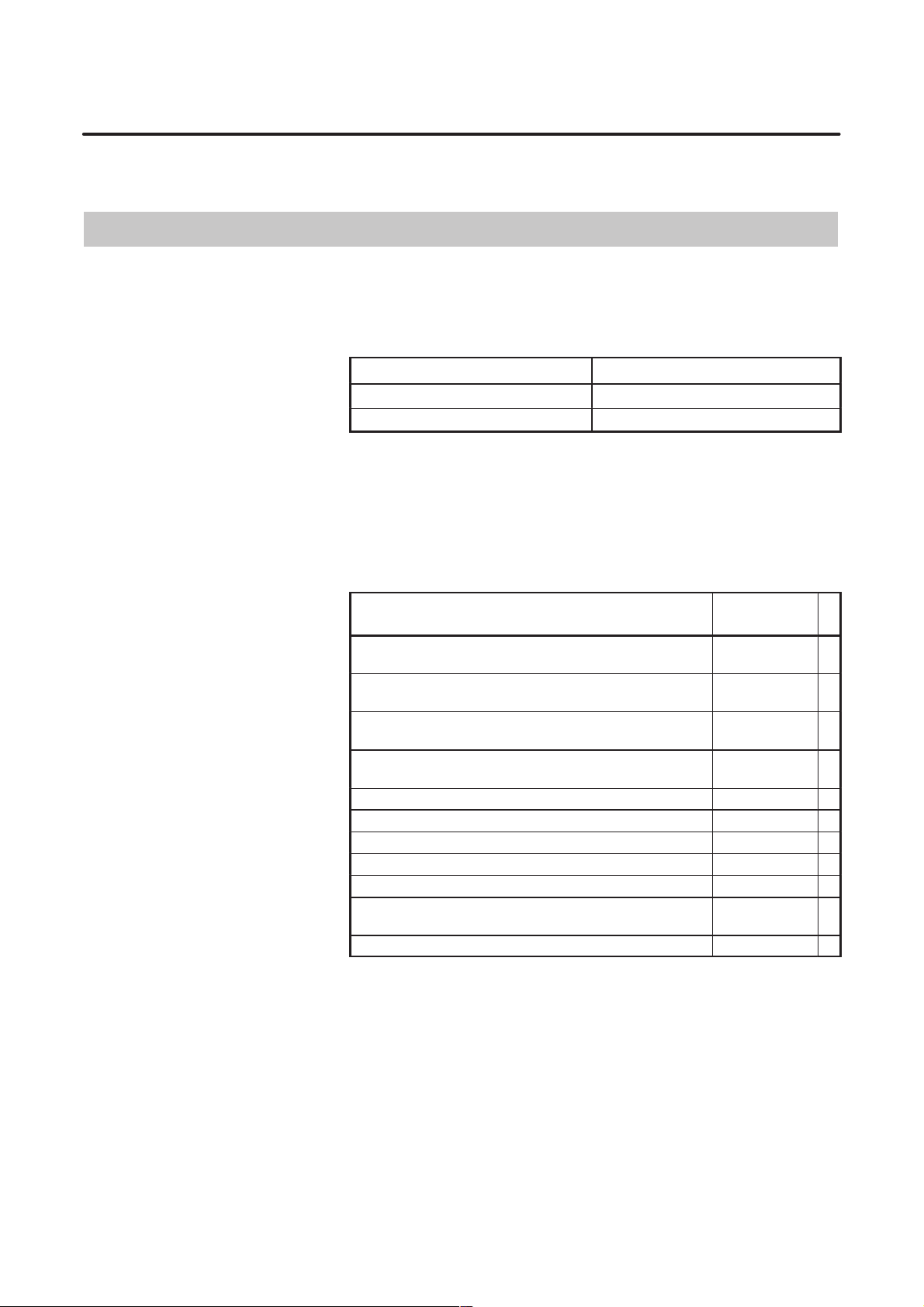
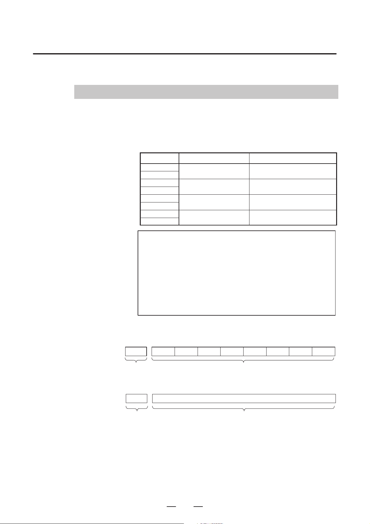
Parameters are classified by data type as follows:
Table 4 Data T ypes and Valid Data Ranges of Parameters
Data type Valid data range Remarks
Bit
Bit axis
Byte
Byte axis
Word
Word axis
2–word
2–word axis
0 or 1
0 to 255 In some parameters, signs are
0 to 255
–128 to 127
0 to 65535 In some parameters, signs are
0 to 65535
–32768 to 32767
–99999999 to 99999999
4. DESCRIPTION OF PARAMETERS
In some parameters, signs are
ignored.
In some parameters, signs are
ignored.
[Example]
0000
Data No.
1023 Servo axis number of a specific axis
Data No.
NOTE
1 For the bit type and bit axis type parameters, a single data
number is assigned to 8 bits. Each bit has a different
meaning.
2 The axis type allows data to be set separately for each
control axis.
3 The valid data range for each data type indicates a general
range. The range varies according to the parameters. For
the valid data range of a specific parameter, see the
explanation of the parameter.
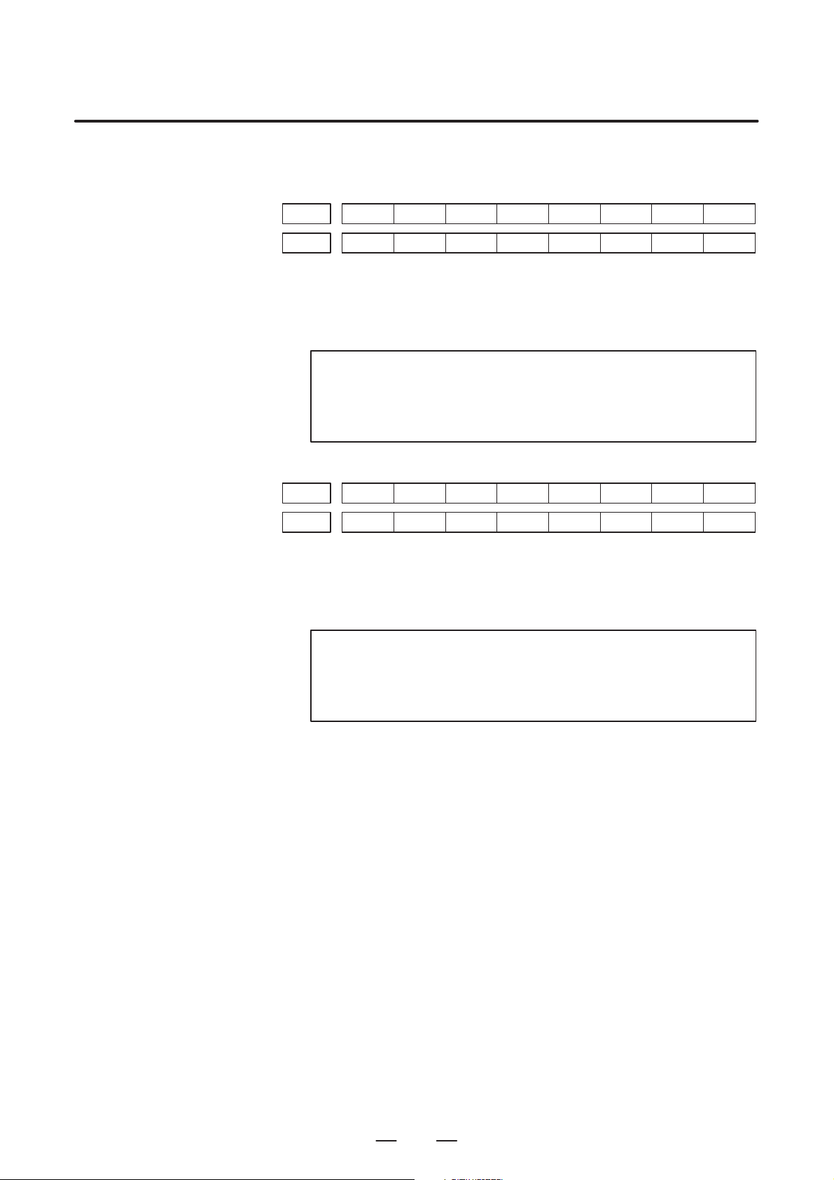
(1) Notation of bit type and bit axis type parameters
#7
#6 #5
SEQ
#4 #3 #2
Data #0 to #7 are bit positions.
INI
#1
ISO
(2) Notation of parameters other than bit type and bit axis type
Data.
#0
TVC
7
Page 13

4. DESCRIPTION OF PARAMETERS
4.1
SETTINGS FOR ENABLING/DISABLIN G FUNCTIONS
[Data type] Bit
15000
LPC Power control is:
LGC The in–tube pressure control gain selection of two types is:
AGA The assist gas is:
BMO When the shutter is closed, the function to turn the beam on is:
#7
#6 #5
FLT
#4
CLB#3BMO#2AGA
0 : Disabled. (Normal operation)
1 : Enabled.
0 : Disabled.
1 : Enabled. (Normal operation)
(When this bit is set to 1, parameter No. 15245 is enabled.)
0 : Enabled. (Normal operation)
1 : Disabled. (Maintenance)
0 : Disabled. (Normal operation)
1 : Enabled. (Manual operation only, maintenance)
B–63200EN/02
#1
LGC
LPC
#0
CLB Power calibration is:
0 : Disabled.
1 : Enabled. (Normal operation)
FLT During power control, the filter is:
0 : Disabled.
1 : Enabled. (Normal operation)
#7
15001
#6
LHC
#5 #4
PC8#3NGC
[Data type] Bit
EXA An assist gas can be selected from:
0 : Three types. (Normal operation)
1 : Seven types.
G0B Beam output by G00 is
0 : Disabled. (Normal operation)
1 : Enabled.
PES In the machine lock or dry run state, the piercing time is:
0 : Executed. (Normal operation)
1 : Not executed.
NGC The integral for gas pressure control is:
0 : Not preset.
1 : Preset.
#2
PES
#1
G0B
#0
EXA
PC8 The power calibration function of:
0 : Correction by constant power.
1 : Power is raised to eight steps.
LHC The oscillator is:
0 : Not controlled by an external signal. (Normal operation)
1 : Controlled by an external signal.
8
Page 14

B–63200EN/02
4. DESCRIPTION OF PARAMETERS
#7
15002
#6
PSH
#5 #4 #3 #2 #1
[Data type] Bit
BMA When the shutter is closed in automatic operation, beam output is:
0 : Disabled. (Normal operation)
1 : Enabled. (Maintenance)
ADC AD conversion–2 data is judged with:
0 : The select signal.
1 : The DI signal. (Normal operation)
PSH Of the discharge tubes,
0 : All are used.
1 : Half are used.
#7
15003
#6 #5 #4 #3 #2
GVW#1HPT
[Data type] Bit
TIV The sign (+/–) of the tracing displacement amount is:
0 : Not inverted.
1 : Inverted.
HPT When piercing is lengthened or reduced, a parameter setting is:
0 : Rewritten.
1 : Not rewritten.
GVW RUN–OFF evacuation is:
0 : Disabled. (Maintenance)
1 : Enabled. (Normal operation)
ADC
#0
BMA
#0
TIV
#7
CWY15004
#6
ECH
#5 #4
EDG
#3 #2
SPB
[Data type] Bit
AGC The ”G32 P_;” command (with Q, T, and R not specified) is used as:
0 : A flow pattern command.
1 : A direct gas pressure control command.
STC The shutter is controlled by:
0 : A G code.
1 : An external signal.
SPB During a skip, beam output is:
0 : Performed.
1 : Not performed.
EDG When the assist gas is switched in edge machining, the beam is:
0 : Turned off.
1 : Not turned off.
ECH Upon reset, the active E number is:
0 : Not cleared.
1 : Cleared.
CWY The oscillator of the:
0 : CO2 laser is used.
1 : CW–YAG laser is used.
#1
STC
#0
AGC
9
Page 15

4. DESCRIPTION OF PARAMETERS
B–63200EN/02
#7
DLY15005
#6
ITR
#5 #4
GNS
[Data type] Bit
INB Beam output is stopped:
0 : Upon the completion of distribution.
1 : After an in–position check.
TTD A single laser power supply unit drives:
0 : A single discharge tube.
1 : Two discharge tubes.
BPV The bypass valve:
0 : Is opened while correcting power.
1 : Is not opened while correcting power.
GNS At the time of assist gas switching, the beam is:
0 : Stopped. (Normal operation)
1 : Not stopped.
ITR Tracing control interlock signal *TRIL (G227, #6) is:
0 : Disabled.
1 : Enabled.
DLY The beam output condition delay function is:
0 : Disabled.
1 : Enabled.
#3
BPV
#2
TTD
#1 #0
INB
#7
15006
#6 #5
PCN
#4
PCL
#3 #2
PIN
#1
TRM#0NCC
[Data type] Bit
NCC The cutting condition setting screen is:
0 : Displayed.
1 : Not displayed.
TRM On the trace setting screen, the zero–point, start–point, and end–point soft
keys are:
0 : Enabled.
1 : Disabled.
PIN The address–P value of G13 is specified using:
0 : Metric input.
1 : Inch input.
PCL The assist gas pressure is displayed on the screen in units of:
2
0 : kg/cm
.
1 : MPa.
PCN When power correction is not executed, the power correction coefficient is:
0 : Rewritten with 1024.
1 : Not rewritten, but remains unchanged from the previous value.
10
Page 16

B–63200EN/02
4. DESCRIPTION OF PARAMETERS
#7
15007
#6 #5
STO
#4
XSC
#3
ECK
#2
ESE
#1 #0
ESE If piercing is to be executed in edge machining, it is:
0 : Executed upon the completion of distribution.
1 : Executed after a smoothing error check is performed upon the
completion of distribution.
ECK In edge machining, the angle is judged with:
0 : The actual machining path.
1 : The path in the machining program.
XSC In exact stop mode, the edge machining function is:
0 : Not executed.
1 : Executed.
STO If an assist gas is specified with the same type and the same flow pattern:
0 : Neither the after flow nor pre flow is executed.
1 : Both the after flow and pre flow are executed.
#7
RMP15008
#6
EGE
#5 #4 #3
SOC
#2
TAL
#1
GPC#0MST
[Data type] Bit
MST The signs (+ and –) of the reference displacement amount indicate the
following directions of tracing:
0 : + indicates approach towards the workpiece, while – indicates
withdrawal from the workpiece.
1 : + indicates withdrawal from the workpiece, while – indicates
approach towards the workpiece.
GPC Tracing control is performed according to:
0 : The reference displacement.
1 : The gap (distance from the nozzle to the workpiece).
TAL If the trace check mode signal (G225#2, TRCKM) is set to 1:
0 : The tracing range over alarm is disabled.
1 : The tracing range over alarm and tracing displacement large alarm are
disabled.
SOC When the machining condition setting function is used, the reference
displacement amount of tracing control is used as the reference
displacement amount of piercing:
0 : Except during machining.
1 : Only during piercing.
EGE The automatic aging function is:
0 : Disabled.
1 : Enabled.
RMP Step control:
0 : Only the up/down step distance.
1 : Both the up/down step distance and specified feedrate.
11
Page 17

4. DESCRIPTION OF PARAMETERS
B–63200EN/02
#7
TEM15009
#6
BCG#5BEM
#4
AFZ
#3
BS2
[Data type] Bit
These parameters are related to the laser gas mixture function, which store
and monitor the operating states of the mixer. The parameters are
automatically set and need not be set manually.
AS2, AS1 Indicate the state of tank A.
AS2 AS1
0 0 : Tank A is being supplied with gases.
0 1 : Tank A is mixing the gases.
1 0 : Tank A is supplying the mixed gas.
1 1 : Tank A is being prepared for gas supply.
BS2, BS1 Indicate the state of tank B.
BS2 BS1
0 0 : Tank B is being supplied with gases.
0 1 : Tank B is mixing the gases.
1 0 : Tank B is supplying the mixed gas.
1 1 : Tank B is being prepared for gas supply.
AFZ In calculation for actual cutting feedrate display, the Z–axis is:
0 : Included.
1 : Not included.
BEM The supply pressure of the gas cylinder:
0 : Has fallen.
1 : Is normal.
BCG The gas cylinder:
0 : Has been replaced.
1 : Has not yet been replaced.
TEM The supply pressure of the tank:
0 : Has fallen.
1 : Is normal.
#2
BS1
#1
AS2
#0
AS1
#7
OVE15010
#6 #5
TRG
#4 #3 #2 #1 #0
[Data type] Bit
TRG The trigger pulse command control function is:
0 : Disabled.
1 : Enabled.
OVE Edge machining and feedrate clamp by arc radius:
0 : Cannot be used at the same time.
1 : Can be used at the same time.
12
Page 18

B–63200EN/02
4. DESCRIPTION OF PARAMETERS
#7
OPV15011
#6 #5
CSC
#4 #3
LVE
#2 #1 #0
[Data type] Bit
EDS The cutting conditions to be assumed during the execution for the return
distance in edge machining and start–up machining are:
0 : The same as usual.
1 : Not the same as usual. For the laser power, assist gas type, and assist
gas pressure, the piercing operation conditions for edge machining are
used.
LVE The assist gas switching to be performed at the start of edge machining
and at the start of the subsequent return distance cutting is:
0 : Of the conventional type.
1 : Not of the conventional type. If the gas type and gas pressure do not
change, the stabilization time is ignored.
CSC If, in start–up machining mode, the four items S, P , Q, and F are specified
at the same time in the first G01, G02, or G03 block after G24:
0 : Start–up machining is executed as usual, regardless of the
specification of S, P, Q, and F.
1 : The start–up machining operation is canceled, and cutting is
performed with the specified S, P, Q, F values.
OPV The external piping exhaust valve:
0 : Is operated only once after the power is turned on. (Same as usual)
1 : Is always operated at RUN–ON time.
EDS
13
Page 19
4. DESCRIPTION OF PARAMETERS
4.2
B–63200EN/02
DISCHARGE TUBE SELECTION
[Data type] Bit
PS1 to PS16 Discharge tube selection when half of the discharge tubes are used
[Data type] Bit
PS1 to PS16 Discharge tube selection when all of the discharge tubes are used
#7
PS815025
PS1615026 PS15 PS14 PS13 PS12 PS11 PS10 PS9
#6
PS7
#5
PS6
#4
PS5
#3
PS4
#2
PS3
#1
PS2
#0
PS1
Four of eight discharge tubes can be selected. Set the bit corresponding to
the discharge tube to be used to 1. Set the other bits to 0.
NOTE
Parameter No.15026 is provided for extension of the
discharge tubes. This parameter is not used at present. Set
all bits to 0.
#7
PS815027
PS1615028 PS15 PS14 PS13 PS12 PS11 PS10 PS9
#6
PS7
#5
PS6
#4
PS5
#3
PS4
#2
PS3
#1
PS2
#0
PS1
All of the eight discharge tubes can be selected. Set the bit corresponding
to the discharge tube to be used to 1. Set the other bits to 0.
NOTE
Parameter No.15028 is provided for extension of the
discharge tubes. This parameter is not used at present. Set
all bits to 0.
14
Page 20

B–63200EN/02
4.3
CONTOURING CONDITIONS
[Valid data range] 0 to 7000
[Valid data range] 5 to 2000
4. DESCRIPTION OF PARAMETERS
15040 Output power
[Data type] Word
[Unit of data] W
15041 Pulse frequency
[Data type] Word
[Unit of data] Hz
15042 Pulse duty ratio
[Data type] Word
[Unit of data] %
[Valid data range] 0 to 100
15
Page 21

4. DESCRIPTION OF PARAMETERS
4.4
B–63200EN/02
EDGE MACHINING CONDITIONS
[Data type] Word
[Unit of data] Degree
[Valid data range] 0 to 180
[Data type] Word
[Unit of data] W
[Valid data range] 0 to 7000
[Data type] Word
[Unit of data] Hz
[Valid data range] 5 to 2000
15050 Edge detection angle
When an angle formed by two blocks is smaller than this setting, the
portion is assumed to be a corner.
15051 Piercing peak power
Specify the peak power of piercing at the vertex of a corner.
15052 Piercing pulse frequency
Specify the pulse frequency of piercing at the vertex of a corner.
15053 Piercing pulse duty ratio
[Data type] Word
[Unit of data] %
[Valid data range] 0 to 100
Specify the pulse duty ratio of piercing at the vertex of a corner.
15054 Piercing time
[Data type] Two–word
[Unit of data] Millisecond
[Valid data range] 0 to 99999999
Specify a piercing time at the vertex of a corner.
15055 Piercing assist gas pressure
[Data type] Word
[Unit of data] 0.01 MPa or 0.1 kg/cm
[Valid data range] 0 to 255
Specify a piercing assist gas pressure at the vertex of a corner.
15056 Piercing assist gas type
2
[Data type] Word
[Unit of data]
[Valid data range] 0 to 7
Select the gas type for piercing at the vertex of a corner.
16
Page 22

B–63200EN/02
4. DESCRIPTION OF PARAMETERS
15057 Return distance
[Data type] Two–word
[Unit of data]
Increment system Unit IS–A IS–B IS–C
Metric input mm 0.01 0.001 0.0001
Inch input inch 0.001 0.0001 0.00001
[Valid data range] 0 to 65000
Specify the return distance of movement from the vertex of a corner to the
next block.
15058 Return speed
[Data type] Word
[Unit of data] mm/min
[Valid data range] 0 to 9999
Specify the return speed of movement from the vertex of a corner to the
next block.
15059 Return peak power
[Data type] Word
[Unit of data] W
[Valid data range] 0 to 7000
Specify the return peak power of movement from the vertex of a corner to
the next block.
15060 Return frequency
[Data type] Word
[Unit of data] Hz
[Valid data range] 5 to 2000
Specify the return frequency of movement from the vertex of a corner to
the next block.
15061 Return duty ratio
[Data type] Word
[Unit of data] %
[Valid data range] 0 to 100
Specify the return duty ratio of movement from the vertex of a corner to
the next block.
17
Page 23

4. DESCRIPTION OF PARAMETERS
4.5
PIERCING CONDITIONS
15080 Piercing power
[Data type] Word
[Unit of data] W
[Valid data range] 0 to 7000
15081 Initial frequency of piercing
[Data type] Word
[Unit of data] Hz
[Valid data range] 5 to 2000
B–63200EN/02
Specify a piercing power.
Specify the initial frequency of piercing.
15082 Incremental value of piercing frequency
[Data type] Word
[Unit of data] Hz
[Valid data range] 0 to 2000
Specify a value by which the piercing frequency is incremented.
15083 Initial duty ratio of piercing
[Data type] Byte
[Unit of data] %
[Valid data range] 0 to 100
Specify the initial duty ratio of piercing.
15084 Incremental value of piercing duty ratio
[Data type] Byte
[Unit of data] %
[Valid data range] 0 to 100
Specify a value by which the piercing duty ratio is incremented.
15085 Piercing step time
[Data type] Word
[Unit of data] Millisecond
[Valid data range] 0 to 32767
Specify a piercing step time.
18
Page 24

B–63200EN/02
4. DESCRIPTION OF PARAMETERS
15086 Piercing step count
[Data type] Word
[Unit of data]
[Valid data range] 0 to 32767
Specify the number of piercing steps.
15087 Piercing end time
[Data type] Two–word
[Unit of data] Millisecond
[Valid data range] 0 to 99999999
Specify a piercing end time.
19
Page 25

4. DESCRIPTION OF PARAMETERS
4.6
B–63200EN/02
POWER CONTROL
[Data type] Bit
[Data type] Word
[Unit of data] W
[Valid data range] 0 to 7000
[Data type] Word
[Unit of data] Hz
[Valid data range] 5 to 2000
#7
LP815089
#6
LP7
#5
LP6
#4
LP5
#3
LP4
#2
LPZ
LP* The speed calculation of the power control function:
0 : Does not use the * axis.
1 : Uses the * axis.
When nothing is specified, the system assumes that the first axis (LPX)
and second axis (LPY) are specified.
In general, specify an axis used for interpolation. Do not specify other
axes such as the synchronization axis used for simple synchronization
control or the PMC axis.
15090 Minimum output power
15091 Minimum pulse frequency
#1
LPY
#0
LPX
15092 Minimum pulse duty ratio
[Data type] Word
[Unit of data] %
[Valid data range] 0 to 100
Specify the minimum pulse duty ratio.
15094 Power control filter time constant
[Data type] Word
[Unit of data] Millisecond
[Valid data range] 0 to 32767
Specify the time constant of the power control filter.
15095 Allowable variation in power control speed
[Data type] Byte
[Unit of data] mm/min (in B8F1–08 or earlier, specified unit)
[Valid data range] 0 to 255
Specify the allowable variation in power control speed. This parameter is
effective only when parameter No. 15450 is 0. To set a value equal to
greater than 156, use parameter No. 15450.
20
Page 26

B–63200EN/02
4. DESCRIPTION OF PARAMETERS
#7
EGM15096
#6 #5 #4 #3 #2
[Data type] Bit
PCP During power control, the output is:
0 : Not controlled according to the feedrate.
1 : Controlled according to the feedrate.
PCF During power control, the frequency is:
0 : Not controlled according to the feedrate.
1 : Controlled according to the feedrate.
PCD During power control, the duty ratio is:
0 : Not controlled according to the feedrate.
1 : Controlled according to the feedrate.
EGM In edge machining mode and start–up machining mode:
0 : Power control mode is canceled.
1 : Power control is stopped only during the return distance movement in
edge machining and start–up machining.
Edge machining mode and start–up machining mode refer to the states in
which E numbers specifying the respective cutting conditions for edge
machining and start–up machining have been selected.
PCD
#1
PCF
#0
PCP
15097 Reference value for calculating the output inclination (output when feedrate F is 0)
[Data type] Word
[Unit of data] W
[Valid data range] 0 to 7000
15098 Reference value for calculating the frequency inclination (frequency when feedrate F is 0)
[Data type] Word
[Unit of data] Hz
[Valid data range] 5 to 2000
15099 Reference value for calculating the inclination of the duty ratio (duty ratio when feedrate F is 0)
[Data type] Word
[Unit of data] %
[Valid data range] 0 to 100
21
Page 27

4. DESCRIPTION OF PARAMETERS
4.7
SETTINGS RELATED TO ASSIST GAS PRESSURE AND TIME
15100 Assist gas selection
[Data type] Word
[Unit of data]
[Valid data range] 0 to 7 (when bit 0 of parameter No. 15001 is set to 1)
15101 Flow pattern selection
[Data type] Word
B–63200EN/02
0 to 3 (when bit 0 of parameter No. 15001 is set to 0)
Specify an assist gas type.
[Unit of data]
[Valid data range] 1 to 3
Specify an assist gas flow pattern.
15102 Pre–flow time 1
15103 Pre–flow time 2
15104 Pre–flow time 3
[Data type] Word
[Unit of data] 10 milliseconds
[Valid data range] 0 to 32767
Specify the pre–flow time of the assist gas.
15108 After–flow time 1
15109 After–flow time 2
15110 After–flow time 3
[Data type] Word
[Unit of data] 10 milliseconds
[Valid data range] 0 to 32767
Specify the after–flow time of the assist gas.
22
Page 28

B–63200EN/02
15114 Pre–flow pressure 1
15115 Pre–flow pressure 2
15116 Pre–flow pressure 3
[Data type] Word
[Unit of data] 0.01 MPa or 0.1 kg/cm
[Valid data range] 0 to 255
Specify the pre–flow pressure of the assist gas.
15120 Machining flow pressure 1
15121 Machining flow pressure 2
15122 Machining flow pressure 3
[Data type] Word
[Unit of data] 0.01 MPa or 0.1 kg/cm
4. DESCRIPTION OF PARAMETERS
2
2
[Valid data range] 0 to 255
Specify the machining flow pressure of the assist gas.
15126 After–flow pressure 1
15127 After–flow pressure 2
15128 After–flow pressure 3
[Data type] Word
[Unit of data] 0.01 MPa or 0.1 kg/cm
[Valid data range] 0 to 255
Specify the after–flow pressure of the assist gas.
15132 Maximum assist gas pressure
[Data type] Word
[Unit of data] 0.01 MPa or 0.1 kg/cm
[Valid data range] 0 to 255
Specify a gas pressure with which an analog output of 10V is obtained.
2
2
15135 Assist gas pressure stabilization time
[Data type] Word
[Unit of data] 10 milliseconds
[Valid data range] 0 to 32767
Specify an assist gas pressure stabilization time.
23
Page 29

4. DESCRIPTION OF PARAMETERS
15136 Assist gas pressure
[Data type] Word
[Unit of data] 0.01 MPa or 0.1 kg/cm
[Valid data range] 0 to 255
15137 Stabilization time of the assist gas pressure for piercing
[Data type] Word
[Unit of data] 10 milliseconds
[Valid data range] 0 to 32767
15138 Assist gas pressure for piercing
B–63200EN/02
2
Specify an assist gas pressure.
Specify the stabilization time of the assist gas pressure for piercing.
[Data type] Word
[Unit of data] 0.01 MPa or 0.1 kg/cm
[Valid data range] 0 to 255
Specify an assist gas pressure for piercing.
15139 Assist gas stop time
[Data type] Word
[Unit of data] 10 msec
[Valid data range] 0 to 32767
Specify the wait time in which the assist gas is stopped.
2
24
Page 30

B–63200EN/02
4.8
LASER MAINTENANCE/ INSPECTION TIME DISPLAY FUNCTION
[Data type] Two–word
[Unit of data] 0.1 hour
[Valid data range] 0 to 99999999
[Data type] Two–word
[Unit of data] 0.1 hour
4. DESCRIPTION OF PARAMETERS
15150 Laser RUN–ON period
The total RUN–ON time is automatically specified.
15151 Vacuum pump operation period
[Valid data range] 0 to 99999999
The total operation period of the vacuum pump is automatically specified.
15152 Shutter alarm mask time
[Data type] Word
[Unit of data] Millisecond
[Valid data range] 0 to 32767
Specify a time from when the shutter operation is specified until the alarm
monitor starts.
#7
15153
[Data type] Bit
LCK The leak check function is:
0 : Disabled.
1 : Enabled.
15154 Leak judgment time
#6 #5 #4 #3 #2 #1 #0
LCK
[Data type] Word
[Unit of data] sec
[Valid data range] 3 to 65535
Specify the time in which the valve is to be closed and the in–discharge–
tube pressure is to be maintained for a leak check.
In the specified time, the in–discharge–tube pressure is measured a total of
four times. If 0 to 2 is specified, the leak check function is not executed.
25
Page 31

4. DESCRIPTION OF PARAMETERS
B–63200EN/02
#7
15160
#6 #5 #4 #3 #2 #1
[Data type] Bit
MNT The laser maintenance screen is:
0 : Not displayed.
1 : Displayed.
Even if the screen is not displayed, the storage of compensation
coefficients and the totaling of operation time are performed, so that the
screen can be displayed for confirmation when needed.
MDS On the laser maintenance screen, data entry is:
0 : Disabled.
1 : Enabled.
On the laser maintenance screen, data entry is disabled to prevent end
users from entering operation time and other data items accidentally.
(Data can only be viewed.) Setting this bit enables data entry.
MDS#0MNT
26
Page 32

B–63200EN/02
4.9
PARAMETERS RELATED TO OSCILLATOR CONTROL
[Valid data range] 0 to 32767
4. DESCRIPTION OF PARAMETERS
15200 Power specified for power calibration when half of the discharge tubes are used
[Data type] Word
[Unit of data] W
Specify the power to be specified to obtain a power calibration coefficient
when half of the discharge tubes are used.
15201 Power specified for power calibration when all the discharge tubes are used
[Data type] Word
[Unit of data] W
[Valid data range] 0 to 32767
Specify the power to be specified to obtain a power calibration coefficient
when all the discharge tubes are used.
15203 Power calibration limit
[Data type] Word
[Unit of data]
[Valid data range] 0 to 32767
When the power calibration coefficient exceeds this setting, the output
drop alarm signal (F220#6 MWRN) is output to indicate that the mirror
should be cleaned or replaced.
15204 Power calibration coefficient
[Data type] Word
[Unit of data]
[Valid data range] 0 to 32767
The coefficient is used to calibrate the specified power according to the
actual power. This parameter is automatically specified during power
calibration after the oscillator start signal (G222#6, RUN) is turned on.
15205 Power calibration time
[Data type] Word
[Unit of data] Second
[Valid data range] 0 to 32767
Specify a power calibration time.
27
Page 33

4. DESCRIPTION OF PARAMETERS
15206 Time constant of power sensor input filter
[Data type] Word
[Unit of data] Millisecond
[Valid data range] 8 to 32767
15207 Upper limit on power
[Data type] Word
[Unit of data] W
[Valid data range] 0 to 32767
B–63200EN/02
The time constant is used when the primary delay filter is applied to the
laser power monitor value input from the power sensor.
When the specified power value exceeds this setting after power
calibration and power feedback addition, the actual power is clamped to
this setting.
15208 Laser power feedback gain
[Data type] Word
[Unit of data]
[Valid data range] 0 to 32767
Specify a laser power feedback gain.
15209 Power feedback amount clamp
[Data type] Word
[Unit of data]
[Valid data range] 0 to 32767
The power specification is clamped to this setting in power feedback.
15210 Maximum output power
[Data type] Word
[Unit of data] W
[Valid data range] 0 to 7000
When an output power higher than this setting is specified, the actual
power is clamped to this setting.
15211 Minimum output power
[Data type] Word
[Unit of data] W
[Valid data range] 0 to 7000
When an output power lower than this setting is specified, the actual
power is clamped to this setting.
28
Page 34

B–63200EN/02
4. DESCRIPTION OF PARAMETERS
15212 Upper limit on power when the duty ratio is not clamped
[Data type] Word
[Unit of data] W
[Valid data range] 0 to 32767
When the duty ratio is not clamped to 50% according to parameter No.
15213 and when the specified power exceeds this setting after power
calibration and power feedback addition, the actual power is clamped to
this setting. When 0 is specified, the value of parameter No. 15207 is
assumed.
15213 Criterion for clamping the duty ratio
[Data type] Word
[Unit of data] W
[Valid data range] 0 to 7000
When the product of the specified power and override exceeds this setting,
the duty ratio is always limited to 50%, and the peak value is clamped to
the value specified in parameter No. 15210. When 0 is specified, the value
of parameter No. 15210 is assumed.
15214 Maximum CW–Y AG laser frequency
[Data type] Word
[Unit of data] Hz
[Valid data range] 0 to 32767
The frequency of the CW–YAG laser oscillator is clamped to this setting.
15215 Power input calibration coefficient
[Data type] Word
[Unit of data] W
[Valid data range] 102 (0.1 2
is assumed.)
Specify a power input calibration coefficient.
10
) to 10240 (10 210) (When 0 is specified, 1024 (1 210)
15216 Time constant of power display filter
[Data type] Word
[Unit of data] Millisecond
[Valid data range] 0 to 32767
Specify a time constant for the filter that suppresses flickering of the
power display.
29
Page 35

4. DESCRIPTION OF PARAMETERS
15217 Beam stop delay time
[Data type] Word
[Unit of data] Millisecond
[Valid data range] 0 to 32767
15218 Power for clamping the duty ratio of the CW–Y AG laser
[Data type] Word
[Unit of data] W
[Valid data range] 0 to 32767
B–63200EN/02
Specify the period from when an in–position check is completed until the
beam stops.
When laser power Pc, specified for the CW–YAG laser, exceeds this setting,
the upper limit of the duty ratio is clamped to:
No.15218
Pc
100(%) When
0 is specified, 500 W is assumed.
15219 Beam output condition delay time
[Data type] Byte
[Unit of data] 8 milliseconds
[Valid data range] 0 to 8
Specify the delay time from the point the CNC specifies beam output
conditions until the output conditions for the beam to be output from the
oscillator are actually changed.
30
Page 36

B–63200EN/02
4.10
PARAMETERS RELATED TO DISCHARGE
[Valid data range] 0 to 32767
[Valid data range] 0 to 32767
4. DESCRIPTION OF PARAMETERS
15220 Maximum specifiable bias value at the start of discharge
[Data type] Word
[Unit of data] mV
Specify the maximum bias value that can be specified at the start of
discharge.
15221 Discharge start voltage
[Data type] Word
[Unit of data] V
Specify a discharge start voltage.
15222 Discharge start wait time
[Data type] Word
[Unit of data] 10 milliseconds
[Valid data range] 0 to 32767
Specify a wait time from when the bias value is maximized at the start of
discharge until actual discharge is confirmed.
15223 Bias value
[Data type] Word
[Unit of data] mV
[Valid data range] 0 to 32767
Specify a bias value.
15224 Modulation voltage
[Data type] Word
[Unit of data] mV
[Valid data range] 0 to 3000
V alue by which the normal bias value is to be reduced during modulation.
15225 Modulation time
[Data type] Word
[Unit of data] 10 msec
[Valid data range] 0 to 32767
Time in which the bias value is to be reduced.
31
Page 37

4. DESCRIPTION OF PARAMETERS
4.11
PARAMETERS RELATED TO GAS PRESSURE CONTROL (1)
[Data type] Word
[Unit of data] (1=13 Pa)
[Valid data range] 0 to 32767
[Data type] Word
[Unit of data] (1=13 Pa)
15240 Negative pressure for completing evacuation
15241 In–tube pressure at the start of discharge
B–63200EN/02
The negative pressure is applied to evacuate the discharge tube during the
laser startup sequence.
[Valid data range] 0 to 32767
The discharge tube has the gas pressure at the start of discharge.
15242 In–tube pressure during oscillation (50 Hz)
[Data type] Word
[Unit of data] (1=13 Pa)
[Valid data range] 0 to 32767
The discharge tube has the gas pressure during laser oscillation (50 Hz).
15243 In–tube pressure during oscillation (60 Hz)
[Data type] Word
[Unit of data] (1=13 Pa)
[Valid data range] 0 to 32767
The discharge tube has the gas pressure during laser oscillation (60 Hz).
15244 Gas pressure control gain
[Data type] Word
[Unit of data]
[Valid data range] 0 to 32767
The feedback gain is used to maintain a constant gas pressure in the
discharge tube.
32
Page 38

B–63200EN/02
4. DESCRIPTION OF PARAMETERS
15245 In–tube pressure control gain 2
[Data type] Word
[Unit of data]
[Valid data range] 0 to 32767
Specify a gas pressure control gain for reference discharge. This setting is
valid when bit 1 (LGC) of parameter No. 15000 is set to 1.
15246 Pressure control integral gain
[Data type] Word
[Unit of data]
[Valid data range] 0 to 32767
The setting is the feedback gain of an integral element for gas pressure
control.
15247 Pressure control integral element preset value
[Data type] Word
[Unit of data]
[Valid data range] –32768 to 32767
The setting is the preset value of an integral element for gas pressure
control.
15248 Lowest permissible gas pressure
[Data type] Word
[Unit of data] (1=13 Pa)
[Valid data range] 0 to 32767
When the gas pressure is low but reaches this setting, no alarm is raised.
15249 Gas pressure rise time
[Data type] Word
[Unit of data] Second
[Valid data range] 0 to 32767
Specify a gas pressure rise time in sequence 27.
15255 Evacuation time at RUN start
[Data type] Word
[Unit of data] Second
[Valid data range] 0 to 32767
Specify an evacuation time at RUN start.
33
Page 39

4. DESCRIPTION OF PARAMETERS
15256 RUN–OFF evacuation time
[Data type] Word
[Unit of data] Second
[Valid data range] 600 to 32767
15257 Abnormal vibration detection count
[Data type] Word
[Unit of data]
[Valid data range] 0 to 32767
B–63200EN/02
When bit 2 (GVW) of parameter No. 15003 is set to 1 and when the
oscillator start signal (bit 6 (RUN) of G222) goes to 0, evacuation of the
specified time is executed.
When the abnormal vibration count, detected over ten minutes, is not
smaller than this setting, an alarm is raised.
15258 T ime constant of filter for reducing the laser gas pressure variation
[Data type] Word
[Unit of data] Millisecond
[Valid data range] 17 to 32767 (When the setting is 16 or lower, the filter is disabled.)
15259 RUN–ON evacuation time
[Data type] Word
[Unit of data] Second
[Valid data range] 0 to 32767
Specify a RUN–ON evacuation time.
15260 Discharge valve open time for external piping
[Data type] Byte
[Unit of data] Second
[Valid data range] 0 to 60
Specify the operation time of the external piping discharge valve.
34
Page 40

B–63200EN/02
4.12
HIGHLY REFLECTIVE MA TERIAL ALARMS
[Data type] Word
[Unit of data] W
[Valid data range] 0 to 32767
[Data type] Word
[Unit of data] W
[Valid data range] 0 to 32767
4. DESCRIPTION OF PARAMETERS
15265 Maximum permissible output increase
When the difference between the specified power and actual power
exceeds this value, an alarm 4068 (beam reflection error) is raised.
15266 Output limit
When the actual power exceeds this value, an alarm 4068 (beam reflection
error) is raised.
35
Page 41

4. DESCRIPTION OF PARAMETERS
4.13
LASER POWER/VOLTAGE DECREASE
15270 Normal discharge tube voltage
[Data type] Word
[Unit of data] V
[Valid data range] 0 to 32767
15271 Permissible power decrease
[Data type] Word
[Unit of data] W
B–63200EN/02
Specify a discharge tube voltage in normal reference discharge. This
parameter is automatically rewritten after the discharge start signal
(G222#7 HVON) turned “ON”.
[Valid data range] 0 to 32767
When the difference between the specified power and actual power is not
smaller than this value, an output decrease alarm is raised.
15272 Permissible decrease in discharge tube voltage
[Data type] Word
[Unit of data] V
[Valid data range] 0 to 32767
When the difference in the discharge tube voltage between the laser being
used and at laser activation is not smaller than this value, an alarm 4088
(voltage decrease) is raised.
15276 Laser gas replacement time
[Data type] Word
[Unit of data] Second
[Valid data range] 0 to 32767
Time after which new gas is to be injected to the internal piping system.
36
Page 42

B–63200EN/02
4.14
POWER TABLE SETTINGS
[Valid data range] 0 to 32767
[Standard setting] Refer to the appended parameter sheet.
4. DESCRIPTION OF PARAMETERS
15280 Power table interval when half of the discharge tubes are used
15281 Power table interval when all of the discharge tubes are used
[Data type] Word
[Unit of data]
Specify a power setting interval, in Watts.
15290 Value 0 when half of the discharge tubes are used
15291 Value 1 when half of the discharge tubes are used
15292 Value 2 when half of the discharge tubes are used
15293 Value 3 when half of the discharge tubes are used
15294 Value 4 when half of the discharge tubes are used
15295 Value 5 when half of the discharge tubes are used
15296 Value 6 when half of the discharge tubes are used
15297 Value 7 when half of the discharge tubes are used
15298 Value 8 when half of the discharge tubes are used
[Data type] Word
[Unit of data] W
[Valid data range] 0 to 32767
[Standard setting] Refer to the appended parameter sheet.
Specify power settings 0 to 8 at the table intervals, in the indicated order,
when half of the discharge tubes are used.
37
Page 43

4. DESCRIPTION OF PARAMETERS
15300 Value 0 when all of the discharge tubes are used
15301 Value 1 when all of the discharge tubes are used
15302 Value 2 when all of the discharge tubes are used
15303 Value 3 when all of the discharge tubes are used
15304 Value 4 when all of the discharge tubes are used
15305 Value 5 when all of the discharge tubes are used
15306 Value 6 when all of the discharge tubes are used
15307 Value 7 when all of the discharge tubes are used
15308 Value 8 when all of the discharge tubes are used
[Data type] Word
[Unit of data] W
[Valid data range] 0 to 32767
B–63200EN/02
[Standard setting] Refer to the appended parameter sheet.
Specify power settings 0 to 8 at the table intervals, in the indicated order,
when all of the discharge tubes are used.
38
Page 44

B–63200EN/02
4.15
AUTOMATIC AGING FUNCTION
[Data type] Word
[Unit of data] W
[Valid data range] 0 to 7000
[Data type] Word
[Unit of data] Hz
[Valid data range] 5 to 2000
4. DESCRIPTION OF PARAMETERS
15320 Laser power in normal calibration
15321 Oscillation frequency in normal calibration
15322 Pulse duty ratio in normal calibration
[Data type] Word
[Unit of data] %
[Valid data range] 0 to 100
15323 Calibration time of normal calibration
[Data type] Word
[Unit of data] Second
[Valid data range] 0 to 32767
15324 Gas pressure in normal calibration (50 Hz)
[Data type] Word
[Unit of data] (1=13 Pa)
[Valid data range] 0 to 32767
15325 Gas pressure in normal calibration (60 Hz)
[Data type] Word
[Unit of data] (1=13 Pa)
[Valid data range] 0 to 32767
15326 Laser power in aging
[Data type] Word
[Unit of data] W
[Valid data range] 0 to 7000
39
Page 45

4. DESCRIPTION OF PARAMETERS
15327 Oscillation frequency in aging
[Data type] Word
[Unit of data] Hz
[Valid data range] 5 to 2000
15328 Pulse duty ratio in aging
[Data type] Word
[Unit of data] %
[Valid data range] 0 to 100
15329 Calibration time in aging
[Data type] Word
B–63200EN/02
[Unit of data] Second
[Valid data range] 0 to 32767
15330 Gas pressure in aging (50 Hz)
[Data type] Word
[Unit of data] (1=13 Pa)
[Valid data range] 0 to 32767
15331 Gas pressure in aging (60 Hz)
[Data type] Word
[Unit of data] (1=13 Pa)
[Valid data range] 0 to 32767
15332 Pulse frequency in normal calibration
[Data type] Word
[Unit of data] Hz
[Valid data range] 5 to 2000
15333 Pulse duty ratio in normal calibration
[Data type] Word
[Unit of data] %
[Valid data range] 0 to 100
40
Page 46

B–63200EN/02
4. DESCRIPTION OF PARAMETERS
15334 Aging count
[Data type] Word
[Unit of data]
[Valid data range] 0 to 32767 (automatically specified by the CNC)
15335 Time data 1 at HVOFF after LSTR
[Data type] Double word
[Unit of data]
[Valid data range] 0 to 99999999 (automatically specified by the CNC)
15336 Time data 2 at HVOFF after LSTR
[Data type] Double word
[Unit of data]
[Valid data range] 0 to 99999999 (automatically specified by the CNC)
15337 Time data 3 at HVOFF after LSTR
[Data type] Double word
[Unit of data]
[Valid data range] 0 to 99999999 (automatically specified by the CNC)
15338 Time data 4 at HVOFF after LSTR
[Data type] Double word
[Unit of data]
[Valid data range] 0 to 99999999 (automatically specified by the CNC)
15339 Stop time of the oscillator that requires an aging operation
[Data type] Word
[Unit of data] Hour
[Valid data range] 0 to 32767 (valid range: 30 to 120)
If the setting is less than 30, internal processing assumes it to be 60.
The parameters related to automatic aging (Nos. 15320 to 15338) must
not, as a rule, be changed from their preset values or those automatically
set by the CNC.
41
Page 47

4. DESCRIPTION OF PARAMETERS
4.16
PARAMETERS RELATED TO THE PMC–WINDOW
15350 M code for reading a comment
[Data type] Word
[Unit of data]
[Valid data range] 0 to 999
15360 Start address of the R area of the PMC
[Data type] Word
[Unit of data]
[Valid data range] 1 to 997
B–63200EN/02
Specify an M code for reading the comment of function code 140.
Specify the start address of the R area of the PMC.
42
Page 48

B–63200EN/02
4.17
POWER CONTROL (2)
[Data type] Word
[Unit of data] mm/min
[Valid data range] 0 to 32767
[Standard setting] 4
4. DESCRIPTION OF PARAMETERS
15450 Allowable variation in power control speed
Specify the allowable variation in power control speed. If this parameter
is 0, parameter No. 15095 is effective. Parameter No. 15095 and this
parameter have different valid data ranges.
43
Page 49

4. DESCRIPTION OF PARAMETERS
4.18
SETTINGS RELATED TO TRACING (DETECTION)
[Data type] Word
[Unit of data]
[Valid data range] 0 to 65536
[Data type] Word
[Unit of data]
[Valid data range] –32768 to 32767
15500 Detection gain coef ficient
15502 Detection zero point
B–63200EN/02
Specify the gain coefficient of the displacement detector in Z–axis tracing
control.
NOTE
This parameter can be set on the trace setting screen.
The zero point calibration value is used to calibrate the zero point of the
displacement detector in Z–axis tracing control.
NOTE
This parameter can be set on the trace setting screen.
15503 Filter time constant
[Data type] Word
[Unit of data] Millisecond
[Valid data range] 0 to 32767 (Must not set to 1)
[Standard setting] 0
The setting is the time constant of a filter for eliminating the disturbance
component from the displacement in Z–axis tracing control.
15504 Displacement multiplier
[Data type] Word
[Unit of data]
[Valid data range] 1 to 5
[Standard setting] 1
Specify a multiply ratio for supporting a large detection amount in Z–axis
tracing control.
Setting Maximum displacement (mm) Resolution (mm)
1 "2 0.001
2 "4 0.002
3 "6 0.003
4 "8 0.004
5 "10 0.005
44
Page 50

B–63200EN/02
4.19
SETTING RELATED TO TRACING (DISPLAY)
[Data type] Bit
4. DESCRIPTION OF PARAMETERS
#7
15505
#6
TRS
#5
TRA
#4
EBS
#3 #2 #1 #0
EBS The process of establishing the tracing displacement amount standard:
0 : Is of the conventional type. (Data is processed one word at a time.)
1 : Can be expanded. (Data is processed two words at a time.)
TRA The trace setting screen displays the current position using:
0 : The relative coordinate system.
1 : The absolute coordinate system.
TRS TRS Except in tracing mode, the TRERS signal is output if:
0 : The tracing displacement amount > parameter No. 15537.
1 : The tracing displacement amount > (parameter No. 15537 + No.
15539) or the tracing displacement amount < –(parameter No.
15537).
#7
15507
#6 #5 #4 #3 #2 #1 #0
[Data type] Bit
PCH The G codes for tracing control are:
0 : Of the normal type.
1 : Not of the normal type. G13 is a G code dedicated to changing gap
amounts and G14 is a G code with no function.
PCH
45
Page 51

4. DESCRIPTION OF PARAMETERS
4.20
SETTINGS RELATED TO TRACING (INTEGRATION)
15510 Integral time constant
[Data type] Word
[Unit of data] Millisecond
[Valid data range] 0 to 32767
[Standard setting] 0
15511 Integral calibration zero width
[Data type] Word
[Unit of data] 0.001 mm
B–63200EN/02
The integral time constant is used for displacement integration in Z–axis
tracing control.
[Valid data range] 0 to 32767
[Standard setting] 0
The setting is used as a displacement to disable integration in Z–axis
tracing control. The integration is not performed when |(displacement
specified as a reference value)| x (integral calibration zero width).
15512 Integral clamp value
[Data type] Word
[Unit of data] 0.001 mm
[Valid data range] 0 to 32767
[Standard setting] 0
The setting is the integral clamp value for displacement integration in
Z–axis tracing control.
46
Page 52

B–63200EN/02
4.21
SETTINGS RELA TED TO TRACING (PHASE COMPENSATION)
[Data type] Word
[Unit of data] Millisecond
[Valid data range] 0 to 32767
[Standard setting] 0 (A value lower than 2 is invalid.)
[Data type] Word
[Unit of data]
4. DESCRIPTION OF PARAMETERS
15520 Phase compensation time constant
This setting is the time constant for displacement phase compensation in
Z–axis tracing control.
15521 Phase compensation gain
[Valid data range] 0 to 32767
[Standard setting] 0 (A value lower than 2 is invalid.)
Specify a gain for displacement phase compensation in Z–axis tracing
control.
47
Page 53

4. DESCRIPTION OF PARAMETERS
4.22
SETTINGS RELATED TO TRACING (DISPLACEMENT)
[Data type] Word
[Unit of data] 0.001 mm
[Valid data range] Parameter No. 15531 to parameter No. 15532
[Data type] Word
[Unit of data] 0.001 mm
[Valid data range] –32768 to 32767
[Standard setting] 0
15530 Reference displacement
15531 Lower limit on reference displacement
B–63200EN/02
The setting determines the reference distance from the tip of the quill to
the workpiece to be controlled in Z–axis tracing control.
NOTE
This parameter can be set on the tracer setting screen.
Specify the minimum value that can be specified as the reference
displacement for Z–axis tracing control.
15532 Upper limit on reference displacement
[Data type] Word
[Unit of data] 0.001 mm
[Valid data range] –32768 to 32767
[Standard setting] 1000
Specify the maximum value that can be specified as the reference
displacement for Z–axis tracing control.
15533 Displacement causing large displacement alarm
[Data type] Word
[Unit of data] 0.001 mm
[Valid data range] 0 to 32767
[Standard setting] 1200
When a value specified as the reference displacement exceeds this setting
in Z–axis tracing control, a large displacement alarm is raised.
15534 Tracing displacement on workpiece surface
[Data type] Word
[Unit of data] 0.001 mm
[Valid data range] 0 to 32767
This setting indicates the displacement from the surface of the workpiece
to the zero point in tracing control.
48
Page 54

B–63200EN/02
4. DESCRIPTION OF PARAMETERS
15535 Lower limit on gap
[Data type] Word
[Unit of data] 0.001 mm
[Valid data range] 0 to 32767
Specify the minimum value that can be specified for the gap in tracing
control.
15536 Upper limit on gap
[Data type] Word
[Unit of data] 0.001 mm
[Valid data range] 0 to 32767
Specify the maximum value that can be specified for the gap in tracing
control.
15537 Tracing range over alarm
[Data type] Word
[Unit of data] 0.001 mm
[Valid data range] 0 to 32767
[Standard setting] 1000
When the absolute value of the value obtained by subtracting the reference
displacement from the detected displacement exceeds this setting in
Z–axis tracing control, an alarm is raised.
15538 Mask time of tracing range over alarm
[Data type] Word
[Unit of data] Millisecond
[Valid data range] 0 to 32767
[Standard setting] 1000
When the reference displacement amount is changed, an alarm is
suppressed in the transition state for the specified mask time.
15539 Calibration amount of tracing range over alarm
[Data type] Word
[Unit of data] 0.001 mm
[Valid data range] 0 to 32767
[Standard setting] 0
The calibration amount can be added to the detected value of the
approaching side to give the setting of parameter No. 15537.
49
Page 55

4. DESCRIPTION OF PARAMETERS
4.23
SETTINGS RELATED
TO TRACING
(VELOCITY
15540 Velocity control voltage conversion factor of Z–axis tracing control
COMMAND)
15541 Velocity control voltage conversion factor of W–axis tracing control
[Data type] Word
[Unit of data]
[Valid data range] 0 to 32767
B–63200EN/02
Use the following expression to calculate the conversion factor to be
specified:
Conversionfactor + G
G : Tracing control loop gain (second
P 4
1000 Le
2 10*3 4096
–1
)
Le : Amount of machine movement per motor revolution (mm/rev)
P : Number of pulses detected by the pulse coder per motor revolution
(P/rev) (2048 for the serial A or α motor)
15544 Permissible approach acceleration
[Data type] Word
[Unit of data] mm/min
[Valid data range] 0 to 32767
A limit may be imposed on the tracing acceleration (speed increase per 2
msec) to prevent a servo overcurrent alarm from being raised at the start of
tracing. Specify this permissible value.
15545 Displacement amount at which an acceleration limit is imposed during approach
[Data type] Word
[Unit of data] 0.001 mm
[Valid data range] –32768 to 32767
A limit is imposed on the acceleration if the absolute value of the
displacement amount is larger than this setting during tracing approach.
50
Page 56

B–63200EN/02
4.24
SETTINGS RELATED TO TRACING (APPROACH)
[Data type] Word
[Unit of data] 0.001 mm
[Valid data range] 0 to 32767
[Standard setting] 50
4. DESCRIPTION OF PARAMETERS
15550 Approach completion detection range
This setting is the displacement at which the completion of approach is
assumed in Z–axis tracing control. When the displacement stays within
this approach completion detection range for the approach completion
interval time or longer, the system assumes that the approach has been
completed.
15551 Approach completion interval
[Data type] Word
[Unit of data] Millisecond
[Valid data range] 0 to 32767
[Standard setting] 500
When a displacement in Z–axis tracing control stays within the approach
completion detection range for the specified time or longer, the system
assumes that the approach has been completed.
15552 Approach completion detection displacement
[Data type] Word
[Unit of data] 0.001 mm
[Valid data range] 0 to 32767
[Standard setting] 50
Specify the approach completion displacement for approach feed.
15553 Upper limit on feedrate for the approaching side
[Data type] Word
[Unit of data] mm/min
[Valid data range] 0 to 32767
[Standard setting] 1200
Specify an upper limit on the feedrate in an approach.
51
Page 57

4. DESCRIPTION OF PARAMETERS
15554 Constant for clamping Z–axis tracing speed
[Data type] Word
[Unit of data]
[Valid data range] 0 to 32767
15555 Upper limit on feedrate for the withdrawing side
[Data type] Word
[Unit of data] mm/min
B–63200EN/02
The setting is used as the constant for clamping the tracing speed. Specify
the value obtained using the following expression:
Tracing speed clamp constant +
P 4
Le
P : Number of pulses detected by the pulse coder per motor revolution
(P/rev) (2048 for the serial A or α motor)
Le : Amount of machine movement per motor revolution (mm/rev)
[Valid data range] 0 to 32767
[Standard setting] 1200
Specify an upper limit on the feedrate for the withdrawing side.
15556 Constant for clamping W–axis tracing speed
[Data type] Word
[Unit of data]
[Valid data range] 0 to 32767
This setting is used as the constant for clamping the tracing speed. Specify
the value obtained using the following expression:
Tracing speed clamp constant +
P : Number of pulses detected by the pulse coder per motor revolution
(P/rev) (2048 for the serial A or α motor)
Le : Amount of machine movement per motor revolution (mm/rev)
P 4
Le
52
Page 58

B–63200EN/02
4.25
SETTINGS RELATED TO THREE–DIMENSIONA L AXIAL MOVEMENT (ANGULAR AXIS)
4. DESCRIPTION OF PARAMETERS
#7
TDA15600
#6
NFX
#5
NCT
#4
RNC
#3
MIA
#2
NPC
#1 #0
[Data type] Bit
NPC During a stroke check before movement, movement in the G31 block is:
0 : Checked.
1 : Not checked.
MIA During attitude control B, the G53 mode is:
0 : Tip fix mode.
1 : Independent axis mode. (A program containing G53 cannot execute a
neighboring point search and program resumption.)
RNC During movement along an angular axis in manual reference position
return, the X, Y , and Z workpiece coordinates and relative coordinates are:
0 : Updated.
1 : Not updated.
NCT When no command is specified for an intermediate point around the
fourth and fifth axes in spatial circular interpolation (G12),
0 : The attitude does not change from the start point to the intermediate
point.
1 : The intermediate attitude of the attitudes at the start point and the end
point is specified for the intermediate point.
NFX A non–tip–fix command is allowed in memory operation for adjusting the
machine.
0 : The tip–fix operation is performed in memory operation.
1 : The non–tip–fix operation is performed in memory operation.
NOTE
When NFX is set to 1, the value (end point) specified by a
program does not match the coordinates. After adjusting the
machine, reset NFX to 0.
TDA When the attitude around a rotation axis exceeds a point of software
overtravel after three–dimensional conversion:
0 : Rotation in the opposite direction is performed.
1 : The software overtravel is not checked.
53
Page 59

4. DESCRIPTION OF PARAMETERS
B–63200EN/02
#7
OFC15601
#6 #5
RAT
#4
PCK
#3
RDC
#2
RFD
#1
PA5
[Data type] Bit
PA4 The rotation around the fourth axis is:
0 : Counterclockwise.
1 : Clockwise.
PA5 The rotation around the fifth axis is:
0 : Counterclockwise.
1 : Clockwise.
RFD When only the fourth and fifth axes are specified with G01, the feedrate is:
0 : That of parameter No. 15612 or 15613, whichever is lower.
1 : The program–specified feedrate in deg/min.
RDC In three–dimensional conversion, the rotation around the fourth and fifth
axes is:
0 : The same as usual.
1 : Not the same as usual. For the fourth axis, the direction of travel
before the conversion is assumed. If there are two solutions, the one
nearer the amount of travel before the conversion is selected. The
solution for the fifth axis is determined with the solution selected for
the fourth axis.
#0
PA4
PCK The stroke limit check before movement is:
0 : Enabled. (Current setting)
1 : Disabled.
RAT In three–dimensional conversion, the amounts of travel around the fourth
and fifth axes are:
0 : Always taken from the shorter path. (Current setting)
1 : Determined by bits 0 (ROT) and 1 (ROS) of parameter No. 1006 and
bits 0 (ROA) and 1 (ROB) of parameter No. 1008.
OFC When movement around the fourth or fifth axis results in a great
movement along the X–axis, Y–axis, or Z–axis,
0 : The feedrate is not clamped.
1 : The feedrate along the X–axis, Y–axis, or Z–axis is clamped to the
manual rapid traverse rate.
54
Page 60

B–63200EN/02
4. DESCRIPTION OF PARAMETERS
#7
15602
#6
FMX
#5 #4
ZTC
#3 #2 #1
OSL
[Data type] Bit
TGC For interaction control, the rotation of the α axis is specified in a
command:
0 : Using a sign different from that used for the β axis rotation command.
1 : Using the same sign as that used for the β rotation command.
OSL In the pre–travel stroke check, the offset of position control B is:
1 : Not considered.
0 : Considered.
ZTC The tracing axis is:
1 : Always the Z–axis, irrespective of tracing axis selection signal
(G225#0 ZTRM).
0 : Switchable by tracing axis selection signal (G225#0 ZTRM).
FMX If an offset–type nozzle is used, the cutting speed is:
1 : Not clamped.
0 : Clamped by considering the maximum speed after attitude control.
15610 Machine zero–degree position of fset around the fourth axis
#0
TGC
15611 Machine zero–degree position offset around the fifth axis
[Data type] Two–word
[Unit of data]
Increment system Unit IS–A IS–B IS–C
Unit of data deg 0.01 0.001 0.0001
[Valid data range] 0 to 360000
Specify the zero–degree position offsets around the fourth and fifth axes
in that order.
15612 Highest speed in machining feed around the fourth axis
15613 Highest speed in machining feed around the fifth axis
[Data type] Two–word
[Unit of data]
Increment system Unit IS–A IS–B IS–C
Unit of data deg/min 10 1 0.1
[Valid data range] 6 to 15000
Specify the highest speeds in machining feed around the fourth and fifth
axes (rotation axes). To execute interaction control, specify identical
values for the fourth and fifth axes.
55
Page 61

4. DESCRIPTION OF PARAMETERS
15615 Length of the first arm
15616 Length of the second arm
[Data type] Two–word
[Unit of data]
[Valid data range] 0 to 500000 (Millimeter machine)
15617 Interaction gear count for the α axis
[Data type] Byte
[Unit of data]
B–63200EN/02
Increment system Unit IS–A IS–B IS–C
Millimeter machine mm 0.01 0.001 0.0001
Inch machine inch 0.001 0.0001 0.00001
0 to 196850 (Inch machine)
Specify the length of the first and second arms.
[Valid data range] 0 to 127
Specify the interaction gear count for the α axis. When the gear count falls
outside beyond the specified range, specify a value divided by the greatest
common divisor of the gear counts of this axis and the β axis.
Example When the gear count of the α axis is 300 and the gear count of
15618 Interaction gear count for the β axis
[Data type] Byte
[Unit of data]
[Valid data range] 0 to 127
Specify the interaction gear count for the β axis.
The β–axis interaction calibration amount is calculated from the α–axis
interaction gear count specified in parameter No. 15617 and this setting.
The calculated value is automatically specified for the β axis.
β–axis interaction calibration amount = α–axis travel distance)
the β axis is 200, 300:200 = 3:2. Specify 3 as the α axis gear
count and 2 as the β axis gear count.
PRM.15618
PRM.15617
56
Page 62

B–63200EN/02
4. DESCRIPTION OF PARAMETERS
15619 Nozzle length
[Data type] Two–word
[Unit of data]
Increment system Unit IS–A IS–B IS–C
Millimeter machine mm 0.01 0.001 0.0001
Inch machine inch 0.001 0.0001 0.00001
[Valid data range] Parameter No. 15616 + parameter No. 15619 x 500000 (Millimeter
machine)
Parameter No. 15616 + parameter No. 15619 x 196850 (Inch machine)
Specify a nozzle length.
When G71 is executed, the value specified with address R is specified in
this parameter.
15621 Maximum speed 1 after attitude control
[Data type] Two–word axis
[Unit of data, valid data range]
Increment system [Unit of data] IS–A, IS–B IS–C
Millimeter machine 1 mm/min or 1 deg/min 0 to 240000 0 to 100000
Inch machine 0.1 inch/min or 1 deg/min 0 to 96000 0 to 48000
Specify the maximum speed after attitude control. The speed on each axis
may be overridden so as not to exceed this setting.
The maximum speed check is not performed on an axis for which 0 is set.
15622 Maximum speed 2 after attitude control
[Data type] Two–word axis
[Unit of data, valid data range]
Increment system [Unit of data] IS–A, IS–B IS–C
Millimeter machine 1 mm/min or 1 deg/min 0 to 240000 0 to 100000
Inch machine 0.1 inch/min or 1 deg/min 0 to 96000 0 to 48000
Specify the maximum speed after attitude control. The speed on each axis
may be overridden so as not to exceed this setting. This parameter is
effective when the attitude control B speed clamp select signal (G224#7,
OTPMX2) is 1. When OTPMX2 is 0, parameter No. 15621 is effective.
Parameter No. 15621 is effective to an axis for which 0 is set in this
parameter.
57
Page 63

4. DESCRIPTION OF PARAMETERS
B–63200EN/02
15623
Angle at which rotation is assumed to be only plane rotation in three–dimensional
[Data type] Two–word
[Unit of data] 0.001 deg
[Valid data range] 0 to 89999
If, in three–dimensional conversion, the difference between the
inclination of the plane containing three reference points (P1, P2, and P3)
and that of the plane containing three target points (Q1, Q2, and Q3) is
equal to or less than the angle specified in this parameter, the inclination
difference is ignored and the rotation is assumed to be only rotation in the
X–Y plane.
If this parameter is 0, this compensation process is not executed.
15628 Backlash for the fifth–axis program command
[Data type] Word
[Unit of data]
[Valid data range] –9999 to 9999
Backlash is output when the polarity of the travel direction of nozzle arm 2
reverses. That is, backlash is output when the polarity of the fifth–axis
command reverses.
Before changing this parameter, move the tool along the fifth axis in the
reference position return direction and cancel any existing backlash
compensation.
conversion
15629 Backlash for the fifth–axis interaction command
[Data type] Word
[Unit of data] Detection unit
[Valid data range] –9999 to 89999
Backlash is output for the fifth axis when the polarity of the travel
direction of the fourth axis reverses. Before changing this parameter,
move the tool along the fourth axis in the reference position return
direction and cancel any existing backlash compensation.
58
Page 64

B–63200EN/02
4.26
PROGRAM RESUMPTION/NEIGH BORING POINT SEARCH
[Data type] Bit
4. DESCRIPTION OF PARAMETERS
#7
NMT15630
#6
NMC#5NSC
#4
PRT
#3
NRE#2NSR
#1
PRZ
#0
PRS
PRS The program resume function of:
0 : The standard type is used.
1 : The laser type is used.
PRZ While the program resume function is being executed, a Z–axis command
up to the position of resumption is:
0 : Not ignored.
1 : Ignored.
NSR In a sequence number search, the automatic operation in progress signal
(bit 7 (OP) of F007) is:
0 : Output.
1 : Not output.
NRE When the neighboring point search function attempts positioning to the
end point,
0 : Alarm PS4000 (No neighboring point is found) is raised.
1 : The positioning is allowed.
PRT When an attempt is made to execute the program resume function on a
Z–axis tracing program using G13:
0 : Alarm PS4001 is raised. (Current setting)
1 : Search is possible. At the resumption, turn on/off the Z–axis machine
lock (G103#2, MLK3) at the same time as the program resumption
signal REST2. Note that the program must be specified in absolute
mode.
NSC If, with the program resume function of the laser type and the neighboring
point search function, a program is to resume in a spatial corner R
insertion block:
0 : The program resumes at the program–specified point at which a
corner R is not inserted.
1 : The program resumes at the end of the inserted corner R.
NMC With the neighboring point search in attitude control B and the program
resume function, positioning to the point of resumption is:
0 : Executed for all axes at the same time.
1 : Executed for the fourth and fifth axes first, then for the remaining
axes. (Note: Executed in non–interpolation mode.)
NMT If, in a neighboring point search, the block whose end point is near the
reference position is followed by a block without movement:
0 : The system searches for the next block. (Current setting)
1 : The system assumes the block without movement to be a neighboring
point.
59
Page 65

4. DESCRIPTION OF PARAMETERS
15635 Neighboring point distance of neighboring point search
[Data type] Two–word
[Unit of data]
[Valid data range] 0 to 99999999
B–63200EN/02
Increment system Unit IS–A IS–B IS–C
Metric input mm 0.01 0.001 0.0001
Inch input inch 0.001 0.0001 0.00001
Specify the neighboring point distance of neighboring point search.
60
Page 66

B–63200EN/02
4.27
TEACHING BOX
[Valid data range] 1 to 999
4. DESCRIPTION OF PARAMETERS
15638 Start address of teaching box DI area
15639 Start address of teaching box DO area
[Data type] Word
[Unit of data]
The DI/DO area can be assigned to a desired address of the internal relay
area (R area). When an address is specified in parameter No. 15638 or
15639, the area is assigned, starting from the address. This parameter is
effective when bit 1 (TBX) of parameter No. 15641 is 1.
15640 Channel of teaching box
[Data type] Byte
[Unit of data]
[Valid data range] 1, 2
Specify the channel to which the teaching box is connected.
15641
[Data type] Bit
TBE As the channel of the teaching box, the right to occupy the RS–232C port is:
0 : Always held by the CNC. (Current setting)
1 : Switchable by the TBES signal (G226, #6).
TBX The areas used to access DI/DO signals from the teaching box:
0 : Are fixed.
1 : Can be expanded.
TBA The transfer status to the extended battery–powered memory is:
0 : Not output. (Parameter No. 15642 is invalid.)
1 : Output. (Parameter No. 15642 is valid.)
TBO In the teaching box, an eight–digit program number is:
0 : Not used.
1 : Used. (The eight–digit program number option is necessary.)
#7
#6 #5 #4 #3
TBO
#2
TBA
#1
TBX
#0
TBE
61
Page 67

4. DESCRIPTION OF PARAMETERS
15642 Output address of transfer status from TB to extended battery–powered memory
[Data type] Word
[Unit of data]
[Valid data range] 0 to 65528
B–63200EN/02
When an R or S command is specified in the teaching box, the start
address, byte count, completion code, and control bit of the data sent from
the teaching box are set at the address specified in parameter No.15642.
Address specified in parameter No.15642
Start address of data +0
Byte count +2
Completion code +4
Control Bit +6
Control Bit +6
#7 #6 #5 #4 #3 #2 #1 #0
When MSTBA is set to 1, the R or S command is masked.
(If an R or S command is specified while MSTBA is set to 1, an alarm
completion code is output.)
15643 DI size
15644 DO size
[Data type] Byte
[Unit of data] Byte
[Valid data range] 1 to 15 (When 0 is specified, the extension function is disabled.)
Specify the sizes of DI and DO.
Specify the DI size in parameter No.15643 and the DO size in parameter
No.15644. Starting from the address specified in parameter No.15638 and
parameter No.15639, the DI and DO areas of the specified sizes are
assigned. This parameter is valid, when the bit 1 (TBX) of parameter
No.15641 is set to 1.
MSTBA
Start address
Specified in parameter No.15638
Start address
Specified in parameter No.15639
62
Internal relay area
DI
The size is specified in parameter
No.15643.
DO
The size is specified in parameter
No.15644.
Page 68

B–63200EN/02
4.28
SETTINGS RELATED TO MACHINING RESUMPTION
[Data type] Two–word
[Unit of data]
[Valid data range] 1 to 99999999
[Data type] Word
[Unit of data]
4. DESCRIPTION OF PARAMETERS
15650 Z–axis retraction amount
Increment system Unit IS–A IS–B IS–C
Metric input mm 0.01 0.001 0.0001
Inch input inch 0.001 0.0001 0.00001
Specify the amount of Z–axis retraction if it occurs before inverted
movement or skip starts.
15651 Amount of inverted movement
Increment system Unit IS–A IS–B IS–C
Metric input mm 10 1 0.1
Inch input inch 1 0.1 0.01
[Valid data range] 1 to 8000
Specify the amount of inverted movement, which is the distance between
the start and end points of the inverted movement.
15652 Resumption completion distance
[Data type] Word
[Unit of data]
Increment system Unit IS–A IS–B IS–C
Metric input mm 10 1 0.1
Inch input inch 1 0.1 0.01
[Valid data range] 1 to 8000
The system assumes that the inverted movement processing ends when
the amount of travel since a program is resumed after the resumed
non–inverted movement up to the start point of the inverted movement
ends exceeds this setting.
15653 Retry count
[Data type] Word
[Unit of data] Count
[Valid data range] 0 to 100
When a program is resumed after the resumed non–inverted movement up to
the start point of the inverted movement ends, an attempt is made to repeat
the inverted movement processing if inverted movement signal RVS (bit 0 of
G007) is accepted before the resumption completion distance set with
parameter No.15652 is reached. The number of times the processing is
repeated is counted. If the number of times exceeds this setting, the inverted
movement processing is stopped and skip to the next block is performed.
63
Page 69

4. DESCRIPTION OF PARAMETERS
B–63200EN/02
#7
15669
[Data type] Bit
N2S The piercing conditions for the resumed non–inverted movement are:
0 : As specified in the program.
1 : Determined by the values of parameters Nos. 15670 to 15682.
STH In the machining resume function:
0 : The normal specifications are followed after a skip operation.
1 : Z–axis descent, tracing, and piercing are not executed after a skip
operation.
15670 Piercing power
[Data type] Word
[Unit of data] W
[Valid data range] 0 to 7000
Specify the piercing power to be used when the machining resume
function or a skip is executed.
#6 #5 #4 #3 #2 #1
STH
#0
N2S
15671 Initial frequency of piercing
[Data type] Word
[Unit of data] Hz
[Valid data range] 5 to 2000
Specify the initial frequency of piercing to be used when the machining
resume function or a skip is executed.
15672 Incremental value of piercing frequency
[Data type] Word
[Unit of data] Hz
[Valid data range] 0 to 2000
Specify a value by which the piercing frequency is incremented when the
machining resume function or a skip is executed.
15673 Initial duty ratio of piercing
[Data type] Word
[Unit of data] %
[Valid data range] 0 to 100
Specify the initial duty ratio of piercing to be used when the machining
resume function or a skip is executed.
64
Page 70

B–63200EN/02
4. DESCRIPTION OF PARAMETERS
15674 Incremental value of piercing duty ratio
[Data type] Word
[Unit of data] %
[Valid data range] 0 to 100
Specify the value by which the duty ratio of piercing is incremented when
the machining resume function or a skip is executed.
15675 Piercing step time
[Data type] Word
[Unit of data] Millisecond
[Valid data range] 0 to 32767
Specify the piercing step time to be used when the machining resume
function or a skip is executed.
15676 Piercing step count
[Data type] Word
[Unit of data]
[Valid data range] 0 to 32767
Specify the number of piercing steps to be used when the machining
resume function or a skip is executed.
15677 Piercing end time
[Data type] Two–word
[Unit of data] Millisecond
[Valid data range] 0 to 99999999
Specify the piercing end time to be used when the machining resume
function or a skip is executed.
15678 Reference displacement
[Data type] Word
[Unit of data] 0.001 mm
[Valid data range] Parameter No.15531 to parameter No.15532
Specify the reference displacement for piercing to be used when the
machining resume function or a skip is executed. This value determines
the reference distance from the tip of the quill to the workpiece to be
controlled during Z–axis tracing control.
65
Page 71

4. DESCRIPTION OF PARAMETERS
15679 Assist gas selection
[Data type] Word
[Unit of data]
[Valid data range] 0 to 7 (when bit 0 of parameter No. 15001 is set to 1)
15680 Flow pattern selection
[Data type] Word
[Unit of data]
[Valid data range] 1 to 3
15681 Assist gas pressure stabilization time for piercing
B–63200EN/02
0 to 3 (when bit 0 of parameter No. 15001 is set to 0)
Specify the assist gas type to be selected when the machining resume
function or a skip is executed.
Select the assist gas flow pattern to be used when the machining resume
function or a skip is executed.
[Data type] Word
[Unit of data] 10 milliseconds
[Valid data range] 0 to 32767
Specify the assist gas pressure stabilization time for piercing to be used
when the machining resume function or a skip is executed.
15682 Assist gas pressure for piercing
[Data type] Word
[Unit of data] 0.01 MPa or 0.1 kg/cm
[Valid data range] 0 to 255
Specify the assist gas pressure for piercing to be used when the machining
resume function or a skip is executed.
2
66
Page 72

B–63200EN/02
4.29
CONSTANT OPTICAL P A TH CONTROL
[Data type] Bit
X to 8 When a move command for the axis of mirror movement is calculated, the
4. DESCRIPTION OF PARAMETERS
#7
815700
#6
#5
7
6
#4
#3
5
4
#2
#1
z
y
corresponding axis is:
0 : Not used.
1 : Used.
NOTE
Specify 0 for the bit corresponding to an axis that is not
present.
#0
x
#7
815701
#6
#5
7
6
#4
#3
5
4
#2
#1
z
y
[Data type] Bit
X to 8 When a move command for the axis of mirror movement is calculated, the
polarity of the move command of each axis to be used for the calculation is:
0 : Negative.
1 : Positive.
NOTE
Specify 0 for the bit corresponding to an axis that is not
present.
#7
MRO15702
#6 #5 #4 #3 #2
MCO#1FMS
[Data type] Bit
TXC During tracing control, the amount of travel along the tracing axis is:
0 : Included in the calculation of the U–axis move command.
1 : Not included in the calculation of the U–axis move command.
FMS Constant optical path control is:
0 : Enabled.
1 : Disabled.
#0
x
#0
TXC
MCO The sign of the compensation amount for the reference position of the axis
of mirror movement is:
0 : Plus.
1 : Minus.
MRO The constant optical path control stop request signal is set to 1 when:
0 : An overtravel occurs on the mirror block axis.
1 : An overtravel occurs on the mirror block axis and the axis specified in
parameter No. 15700.
67
Page 73

4. DESCRIPTION OF PARAMETERS
15703 Mirror block axis selection
[Data type] Byte
[Unit of data]
[Valid data range] 4 to 8
15704 Mirror block axis reference position calibration
[Data type] Word
[Unit of data]
[Valid data range] –32768 to 32767
B–63200EN/02
Specify the axis number of an axis of mirror movement. The axis must not
be the X–axis, Y–axis or Z–axis.
Increment system Unit IS–A IS–B IS–C
Metric input mm 10.0 1.0 0.1
Inch input inch 1.0 0.1 0.01
[Standard setting] 0
Specify a distance from the origin for the position calibration of the mirror
block axis so that an optimum transmission distance can be obtained.
15705 Optical path length calibration coefficient
[Data type] Word
[Unit of data] 1/64
[Valid data range] 64 to 32767
[Standard setting] 128
The total amount of travel along the axis specified in parameter No. 15700
divided by this coefficient is the amount of travel along the mirror block
axis.
68
Page 74

B–63200EN/02
4.30
LASER GAS MIXTURE FUNCTION
[Data type] Word
[Unit of data] Second
[Valid data range] 0 to 32767
[Data type] Word
[Unit of data] Minute
[Valid data range] 0 to 32767
[Standard setting] 60
4. DESCRIPTION OF PARAMETERS
15710 Cylinder level check wait time
Specify a wait time for checking the cylinder level.
15711 Gas mixture wait time
Specify the time from when the tank is filled with gases until the gases are
mixed and ready to be supplied.
15712 Mixer evacuation time
[Data type] Word
[Unit of data] Minute
[Valid data range] 0 to 32767
[Standard setting] 30
Specify the evacuation time for evacuating the mixer. This value is also
used as the evacuation time used for a leak check.
15713 Helium discharge time
[Data type] Word
[Unit of data] Millisecond
[Valid data range] 0 to 32767
Specify the time allowed to discharge helium gas from the piping after the
piping is filled with helium gas and before being filled with another gas.
15714 Nitrogen and CO2 discharge time
[Data type] Word
[Unit of data] Millisecond
[Valid data range] 0 to 32767
Specify the time allowed to discharge nitrogen or CO
after the piping is filled with nitrogen or CO
another gas.
69
from the piping
2
and before being filled with
2
Page 75

4. DESCRIPTION OF PARAMETERS
15715 Degree of vacuum of gas pressure
[Data type] Word
[Unit of data] (1=13 Pa)
[Valid data range] 0 to 32767
15716 Evacuation wait time
[Data type] Word
[Unit of data] Minute
[Valid data range] 0 to 32767
B–63200EN/02
The degree of vacuum of the laser gas pressure in the gas mixer is
measured. When the laser gas pressure is below the setting, an alarm is
raised.
Specify an evacuation wait time. When 0 is specified, 30 is assumed.
70
Page 76

B–63200EN/02
4.31
THE STEP CONTROL FUNCTION
[Data type] Word
[Unit of data]
[Valid data range] 0 to 65000
4. DESCRIPTION OF PARAMETERS
15730 Distance of a single ramp–up step
Increment system Unit IS–A IS–B IS–C
Metric input mm 0.01 0.001 0.0001
Inch input inch 0.001 0.0001 0.00001
Specify the distance of a single ramp–up step during step control.
15731 Laser power of ramp–up step 1
15732 Laser power of ramp–up step 2
15733 Laser power of ramp–up step 3
15734 Laser power of ramp–up step 4
15735 Laser power of ramp–up step 5
15736 Laser power of ramp–up step 6
15737 Laser power of ramp–up step 7
15738 Laser power of ramp–up step 8
15739 Laser power of ramp–up step 9
15740 Laser power of ramp–up step 10
[Data type] Word
[Unit of data] W
[Valid data range] 0 to 7000
Specify the laser powers of the ramp–up steps during step control.
15745 Distance of a single ramp–down step
[Data type] Word
[Unit of data]
Increment system Unit IS–A IS–B IS–C
Metric input mm 0.01 0.001 0.0001
Inch input inch 0.001 0.0001 0.00001
[Valid data range] 0 to 65000
Specify the distance of a single ramp–down step during step control.
71
Page 77

4. DESCRIPTION OF PARAMETERS
15746 Laser power of ramp–down step 1
15747 Laser power of ramp–down step 2
15748 Laser power of ramp–down step 3
15749 Laser power of ramp–down step 4
15750 Laser power of ramp–down step 5
15751 Laser power of ramp–down step 6
15752 Laser power of ramp–down step 7
15753 Laser power of ramp–down step 8
15754 Laser power of ramp–down step 9
15755 Laser power of ramp–down step 10
[Data type] Word
[Unit of data] W
B–63200EN/02
[Valid data range] 0 to 7000
Specify the laser powers of the ramp–down steps during step control.
72
Page 78

B–63200EN/02
4.32
STEP FEED FUNCTION AND RETURN FUNCTION
[Data type] Two–word
[Unit of data, valid data range]
4. DESCRIPTION OF PARAMETERS
15770 Feedrate of step feed or return
Increment system Unit of data
Millimeter machine system 1 mm/min 0 to 240000 0 to 100000
Inch machine system 0.1 inch/min 0 to 96000 0 to 48000
Valid data range
IS–A, IS–B IS–C
Specify the feedrate to be used when the step feed or return function is
specified from the teaching box.
15771 Wait time after which C command processing will be executed
[Data type] Word
[Unit of data] 16 msec
[Valid data range] 0 to 10
Specify the wait time after which the teaching box C command will be
executed.
73
Page 79

4. DESCRIPTION OF PARAMETERS
4.33
PARAMETERS RELATED TO GAS PRESSURE CONTROL (2)
[Data type] Bit
15800
TPC The turbo blower constant–power drive control function is:
#7
0 : Disabled.
1 : Enabled.
B–63200EN/02
#6 #5 #4 #3 #2 #1 #0
TPC
15801
Maximum in–tube pressure when the turbo blower constant–power drive control
[Data type] Word
[Unit of data] (1=13 Pa)
[Valid data range] 1 to 32767
Maximum in–laser–tube pressure. If the in–laser–tube pressure
calculated from the specified laser power value exceeds the setting of this
parameter, the pressure is clamped to the setting.
15802
Laser power that yields the maximum in–tube pressure when the turbo blower
[Data type] Word
[Unit of data] W
[Valid data range] 1 to 32767
Laser power that yields the in–laser–tube pressure equal to the setting of
parameter No. 15801. This parameter and parameter No. 15801 are used
to determine the proportional constant for the in–laser–tube gas pressure
and the laser power.
15803
In–tube pressure compensation coefficient when the turbo blower constant–power
function is enabled
constant–power drive control function is enabled
drive control function is enabled
[Data type] Word
[Unit of data] 1/1024
[Valid data range] 0 to 32767
Compensation coefficient by which the in–laser–tube pressure is to be
multiplied. A parameter setting of 1024 corresponds to a compensation
coefficient of 1.0.
15804
Maximum open time of the exhaust valve for controlling the in–tube pressure during
[Data type] Word
[Unit of data] msec
[Valid data range] 0 to 3000
Specify the maximum open time of the exhaust valve PCV.
oscillation
74
Page 80

B–63200EN/02
Index
[A]
Automatic Aging Function, 39
[C]
Constant Optical Path Control, 67
Contouring Conditions, 15
[D]
Description of Parameters, 7
Discharge Tube Selection, 14
Displaying Parameters, 1
[E]
Edge Machining Conditions, 16
[H]
Highly Reflective Material Alarms, 35
[ I ]
Inputting and Outputting Parameters Through the
Reader/Puncher Interface, 4
Inputting Parameters through the Reader/Puncher In-
terface, 6
Parameters Related to Gas Pressure Control (1), 32
Parameters Related to Gas Pressure Control (2), 74
Parameters Related to Oscillator Control, 27
Parameters Related to the PMC–WINDOW, 42
Piercing Conditions, 18
Power Control, 20
Power Control (2), 43
Power Table Settings, 37
Program Resumption/Neighboring Point Search, 59
[S]
Setting Parameters from MDI, 2
Setting Related to Tracing (Display), 45
Settings for Enabling/Disabling Functions, 8
Settings Related to Assist Gas Pressure and Time, 22
Settings Related to Machining Resumption, 63
Settings Related to Three–Dimensional Axial Move-
ment (Angular Axis), 53
Settings Related to Tracing (Approach), 51
Settings Related to Tracing (Detection), 44
Settings Related to Tracing (Displacement), 48
Settings Related to Tracing (Integration), 46
Settings Related to Tracing (Phase Compensation), 47
Settings Related to Tracing (Velocity Command), 50
Step Feed Function and Return Function, 73
[L]
Laser Gas Mixture Function, 69
Laser Maintenance/Inspection Time Display Function,
25
Laser Power/Voltage Decrease, 36
[O]
Outputting Parameters through the Reader/Puncher
Interface, 5
[P]
Parameters Related to Discharge, 31
[T]
Teaching Box, 61
The Step Control Function, 71
i–1
Page 81

Revision Record
FANUCĄSeriesĄ16i/160i – LA PARAMETER MANUAL (B–63200EN)
– Position control B speed clamp function
– Gas pressure control
Addition of following parameters
– Other functions
Correction of errors
Feb., 1998
02 Jul., 2000
01
Edition Date Contents Edition Date Contents
Page 82

· No part of this manual may be
reproduced in any form.
· All specifications and designs
are subject to change without
notice.
 Loading...