

Page 1

GE Fanuc Automation
Computer Numerical Control Products
Series 15i / 150i – Model A
Remote Buffer
Descriptions Manual
B-6322EN-1/01 1999
Page 2

Warnings and notices for
GFLE-003
this publication
Warning
In this manual we have tried as much as possible to describe all the various
matters. However, we cannot describe all the matters which must not be done,
or which cannot be done, because there are so many possibilities.
Therefore, matters which are not especially described as possible in this
manual should be regarded as “impossible”.
Notice
This document is based on information available at the time of its publication. While efforts have
been made to be accurate, the information contained herein does not purport to cover all details or
variations in hardware or software, nor to provide every contingency in connection with
installation, operation, or maintenance. Features may be described herein which are not present in
all hardware and software systems. GE Fanuc Automation assumes no obligation of notice to
holders of this document with respect to changes subsequently made.
GE Fanuc Automation makes no representation or warranty, expressed, implied, or statutory with
respect to, and assumes no responsibility for accuracy, completeness, sufficiency, or usefulness of
the information contained herein. No warranties of merchantability or fitness for purpose shall
apply.
The following are Registered Trademarks of GE Fanuc Automation
CIMPLICITY® Genius®
The following are Trademarks of GE Fanuc Automation
Alarm Master
CIMSTAR
Field Control
Genet
Helpmate
LogicMaster
Modelmaster
PowerMotion
ProLoop
PROMACRO
Series Five
Series 90
Series One
Series Six
Series Three
VuMaster
Workmaster
© Copyright 1998 FANUC Ltd.
Authorized Reproduction GE Fanuc Automation Europe S.A.
All Rights Reserved
No part of this manual may be reproduced in any form.
All specifications and designs are subject to change without notice.
Page 3

B-63322EN-1/01 PREFACE
PREFACE
Applicable product name
The models covered by this manual, and their abbreviations are:
Product name Abbreviations
FANUC Series 15i-MA 15i-MA Series 15i
FANUC Series 150i-MA 150i-MA Series 150i
Related manuals
The table below lists manuals related to MODEL A of Series 15i, and
Series 150i. In the table, this manual is marked with an asterisk (*).
Table 1 (a) Related manuals
Manual name
DESCRIPTIONS B-63322EN
CONNECTION MANUAL (Hardware) B-63323EN
CONNECTION MANUAL (Function) B-63323EN-1
OPERATOR’S MANUAL (PROGRAMMING)
for Machining Center
OPERATOR’S MANUAL (OPERATION)
for Machining Center
MAINTENANCE MANUAL B-63325EN
PARAMETER MANUAL B-63330EN
DESCRIPTIONS (Supplement for Remote Buffer) B-63322EN-1 *
Specification
number
B-63324EN
B-63324EN-1
p-1
Page 4

B-63322EN-1/01
CONTENTS
PREFACE ................................................................................................................ p-1
1. GENERAL.............................................................................................................1
2. INTERFACE BETWEEN REMOTE BUFFER AND
HOST COMPUTER.............................................................................................2
2.1 ELECTRICAL INTERFACE ..................................................................................................... 3
2.2 SOFTWARE INTERFACE........................................................................................................ 4
3. ELECTRICAL INTERFACE.............................................................................5
3.1 TRANSMISSION SYSTEM....................................................................................................... 6
3.2 RS-232-C INTERFACE.............................................................................................................. 7
3.3 RS-422 INTERFACE................................................................................................................ 10
4. PROTOCOL A....................................................................................................13
4.1 MESSAGE FORMAT .............................................................................................................. 14
4.2 CODE SYSTEM....................................................................................................................... 14
4.3 COMMUNICATION SYSTEM............................................................................................... 15
4.4 COMMAND ............................................................................................................................. 17
4.4.1 Command Table.............................................................................................................................17
4.4.2 Description of Data Part.................................................................................................................19
4.5 PARAMETER TABLE............................................................................................................. 23
4.6 ERROR PROCESS................................................................................................................... 24
4.7 STATUS TRANSITION........................................................................................................... 25
5. EXPANSION PROTOCOL A...........................................................................26
5.1 COMMUNICATION SYSTEM............................................................................................... 27
5.2 DATA PACKET FORMAT ..................................................................................................... 28
5.3 MONITOR PACKET FORMAT.............................................................................................. 30
5.4 COMMUNICATION EXAMPLE............................................................................................ 32
6. PROTOCOL B....................................................................................................41
6.1 COMMUNICATION SYSTEM............................................................................................... 42
6.1.1 When the CNC Alarm/Reset is not Posted to the Host...................................................................42
6.1.2 When the CNC Alarm/Reset is Posted to the Host.........................................................................44
6.2 CONTROL CODE.................................................................................................................... 48
6.3 BUFFER CONTROL................................................................................................................ 48
6.4 ALARM AND RESET OF CNC.............................................................................................. 49
7. EXPANSION PROTOCOL B (RS-422)...........................................................50
c-1
Page 5

CONTENTS B-63322EN-1/01
8. DATA INTERFACE ..........................................................................................51
8.1 DATA PART ............................................................................................................................ 52
8.2 INTERFACE OF DATA PART ............................................................................................... 52
9. BINARY INPUT OPERATION FUNCTION .................................................53
9.1 FUNCTION EXPLANATION ................................................................................................. 54
9.2 TRANSFER RATE................................................................................................................... 57
9.3 NOTES......................................................................................................................................58
10. PARAMETER.....................................................................................................59
10.1 INPUT DEVICE NUMBER..................................................................................................... 60
10.2 EXCLUSIVE PARAMETER FOR REMOTE BUFFER......................................................... 61
10.3 PARAMETERS RELATED TO BINARY INPUT OPERATION.......................................... 67
11. ALARM ...............................................................................................................70
12. MAINTENANCE................................................................................................71
12.1 LED INDICATIONS ................................................................................................................ 71
12.1.1 Normal State ..................................................................................................................................71
12.1.2 System Errors.................................................................................................................................72
12.2 MATERIAL FOR REMOTE BUFFER TROUBLESHOOTING............................................ 74
12.3 DETERMINING THE LOGICAL SLOT NUMBER OF
THE REMOTE BUFFER BOARD .......................................................................................... 76
12.3.1 Determining the Logical Slot Number on the Screen Displayed
at the Time a System Alarm Occurs......................................................................................76
12.3.2 Determining the Logical Slot Number on the System Configuration Screen.........................77
c-2
Page 6

Page 7
B-63322EN-1/01 1. GENERAL
1 GENERAL
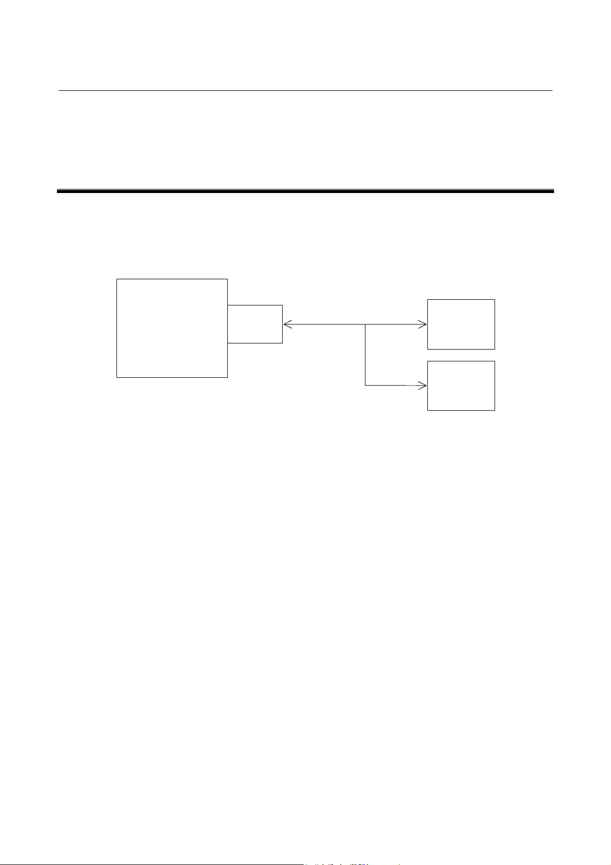
The remote buffer for FANUC Series 15i/150i-MODEL A is an
option and is used to allow a large number of data to be continuously
supplied to the CNC at high speed by connecting it to the host
computer or I/O device through a serial interface.
15i/150i-MA
Remote
buffer
The followings can be performed by the remote buffer.
1) It is used to perform DNC operation at high speed and with high
reliability by performing on-line connection to the host
computer.
2) It is used to download the NC program and parameters from the
host computer. When protocol B or expansion protocol B is
used, NC programs and parameters can also be uploaded to the
host computer.
3) It is used to perform DNC operation and download various kinds
of data by connecting to the I/O device. The following I/O
devices can be connected.
RS-232-C/RS-422
Host
computer
I/O device
(1) FANUC PROGRAM FILE Mate
(2) FANUC HANDY FILE
Hereafter, the destination where the remote buffer is connected to is
called “Host computer” for ease of explanation.
-1-
Page 8

2. INTERFACE BETWEEN REMOTE BUFFER AND HOST COMPUTER B-63322EN-1/01
2 INTERFACE BETWEEN REMOTE BUFFER
AND HOST COMPUTER
-2-
Page 9

B-63322EN-1/01 2. INTERFACE BETWEEN REMOTE BUFFER AND HOST COMPUTER
2.1
ELECTRICAL INTERFACE
The following which interfaces are provided as standard
specifications.
1) RS-232-C interface
2) RS-422 interface (Note 1)
Interface Serial voltage interface
(start-stop system)
Baud rate 50 – 19200 baud rate
(Note 2)
Cable length
(MAX.)
NOTE
1 When the baud rate exceeding 38400 BPS is used, the
synchronization of reception clock is required. Prepare
the TT (*TT ) and RT (*RT) signals.
2 When t he baud r at e used is 19200 baud or more, use the
RS-422 interface.
100m (4800 baud or less)
50m (9600 baud)
15m (19200 baud)
It differs depending on I/O
devices.
RS-232-C RS-422
Balance transmission serial
interface (start-stop system)
50 – 86400 baud rate
(Note 1)
Approximately 800m
(9600 baud or less)
50m (19200 baud or more)
-3-
Page 10

2. INTERFACE BETWEEN REMOTE BUFFER AND HOST COMPUTER B-63322EN-1/01
2.2
SOFTWARE INTERFACE
The following four protocols for communication between the remote
buffer and host computer are provided. The protocol meeting the
requirement of specifications of connection device can be selected by
setting a parameter.
Protocol Features of protocol
where transmit/receive is
repeated between the both.
Expansion
protocol
A
ProtocolBIt is the system for controlling
Expansion
protocol
B
It is nearly the same as the
protocol A. However, the NC
program can be transferred at
high-speed so that it can be
applied to the high-speed DNC
operation.
the communication between the
both by the control code output
from the remote buffer.
The control system is the same
as that of protocol B. However,
it allows the transmission speed
to be increased. In this case, it
is required to receive the
reception synchronization clock
from the source.
Interface
used
RS-232-C 19200 BPSProtocolAIt is the handshake system
RS-422 86400 BPS
RS-422 86400 BPS
RS-232-C 19200 BPS
RS-422 86400 BPS
Transfer
rate (Max.)
NOTE
The average data transfer speed becomes smaller than
the maximum transfer speed.
-4-
Page 11

B-63322EN-1/01 3. ELECTRICAL INTERFACE
3 ELECTRICAL INTERFACE
-5-
Page 12
3. ELECTRICAL INTERFACE B-63322EN-1/01
3.1
TRANSMISSION SYSTEM
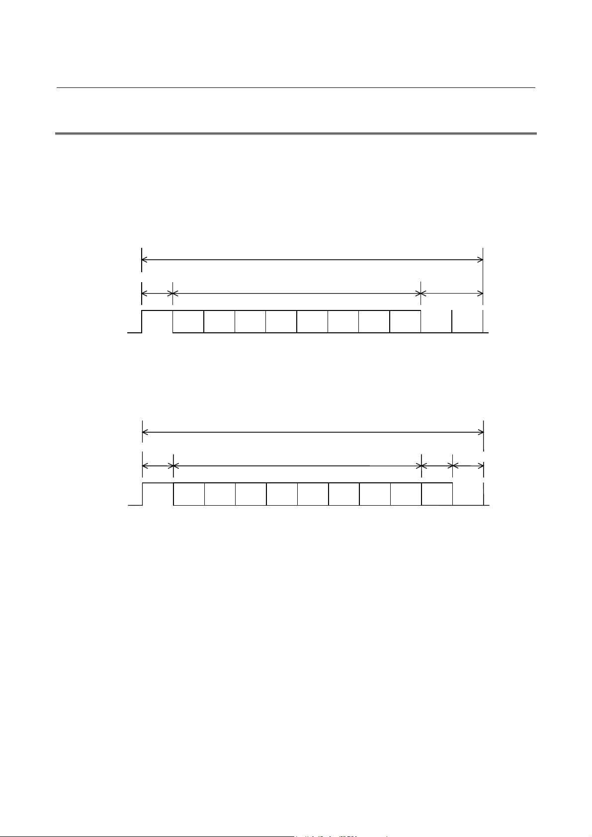
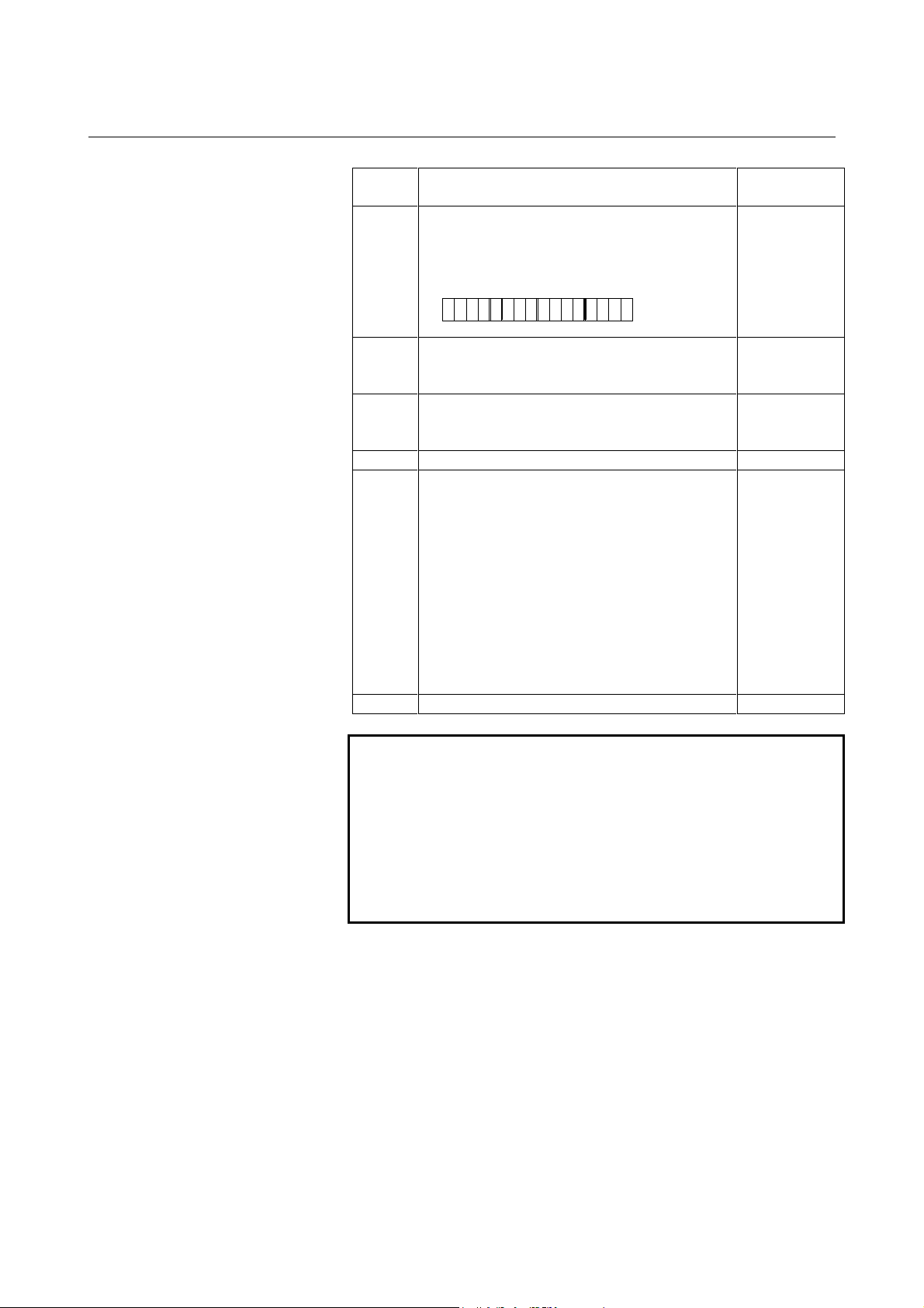
It is the start-stop system for adding the start bit before and stop bit
after the information bits, respectively.
The format for adding one parity bit to each byte of data to be
transmitted is also allowed.
1) Format with no parity bit
1 character
Start bit Stop bit
ON
b1 b2 b5b4b3 b8b7b6
OFF
LSB MSB
Data bit is sent starting from the LSB.
2) Format with parity bit
Data bit
ON
OFF
Start bit
1 character
Data bit
LSB MSB
Data bit is sent starting from the LSB.
The format with parity bit becomes the even parity including a
parity bit. The number of stop bits of parameter determines
whether there is a parity bit or not.
Stop bit 1 → With parity bit
Stop bit 2 → With no parity bit
Parity bit
Stop bit
pb1 b2 b5b4b3 b8b7b6
-6-
Page 13
B-63322EN-1/01 3. ELECTRICAL INTERFACE
3.2
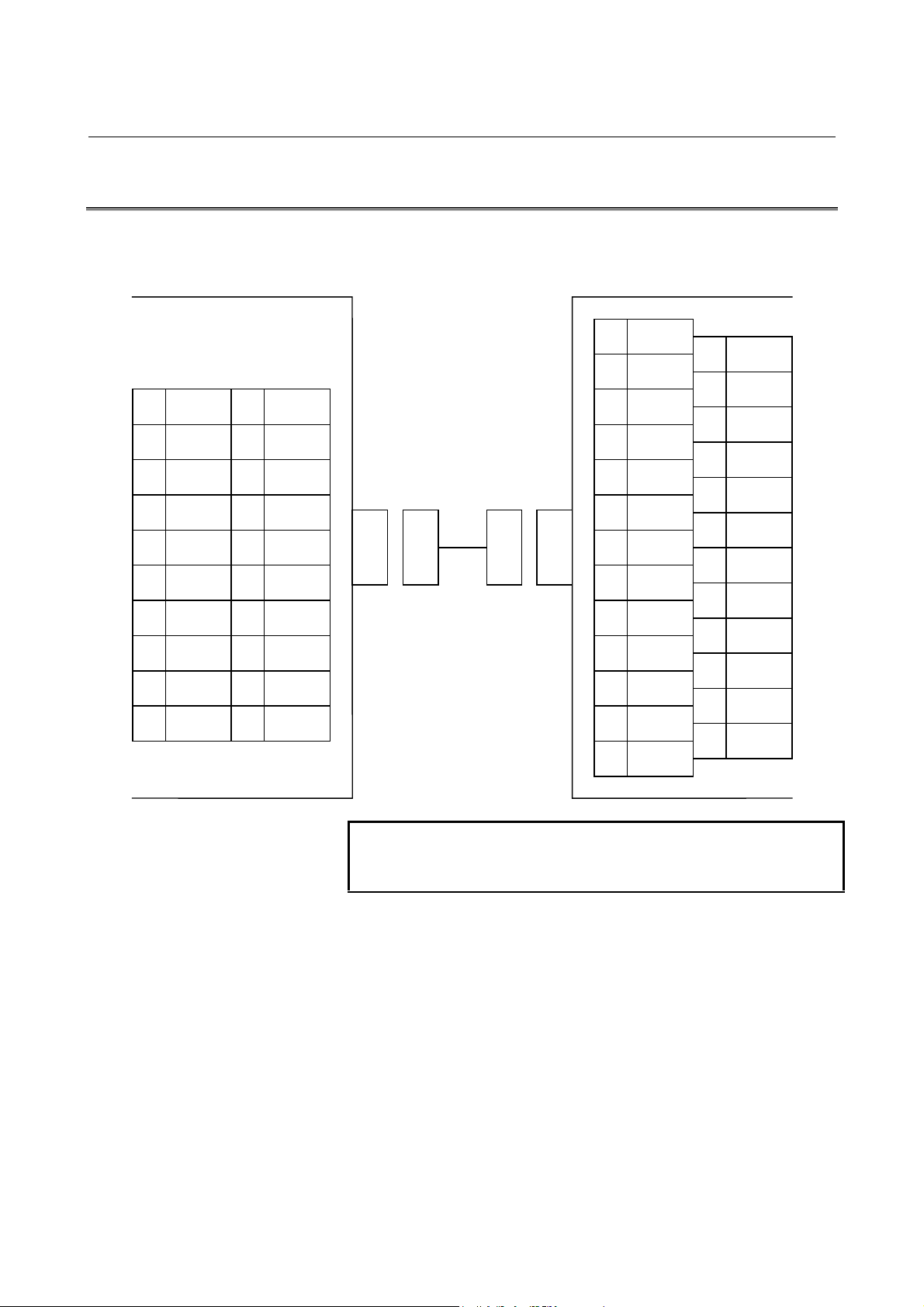
RS-232-C INTERFACE
remote buffer board
CNC
JD5L
(PCR-E20LMDETZ-SL)
1 RD
2 0V
3 DR
4 0V
5 CS
6 0V
7 CD
8 0V
9
10 (+24V)
11 SD
12 0V
13 ER
14 0V
15 RS
16 0V
17
18
19 (+24V)
20
1) Connection between devices
Host compute r (e xample)
(DBM-25S)
1 FG
14
2 SD
15
3 RD
16
4 RS
17
5 CS
18
6 DR
19
7 SG
20 ER
8 CD
21
9
22
10
23
11
24
12
25
13
NOTE
(+24V) is used as the power to FANUC RS-232-C
devices.
-7-
Page 14
3. ELECTRICAL INTERFACE B-63322EN-1/01
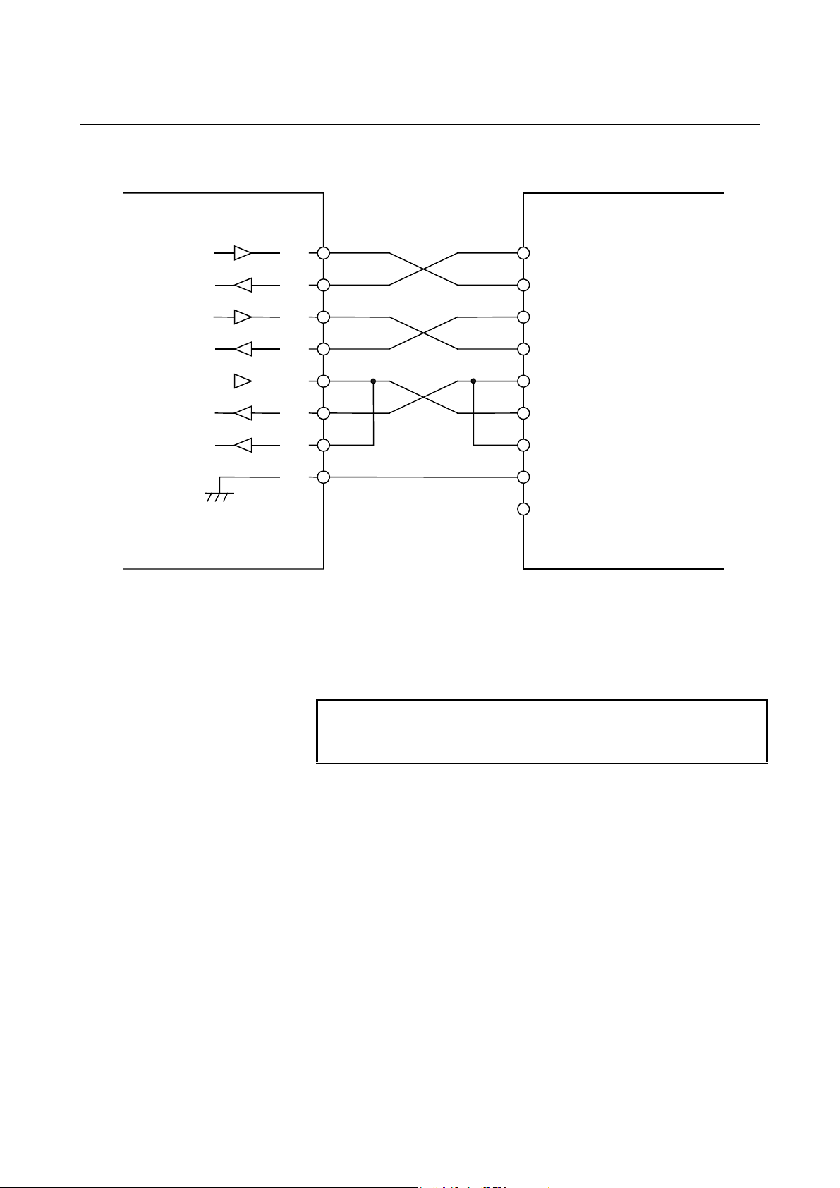
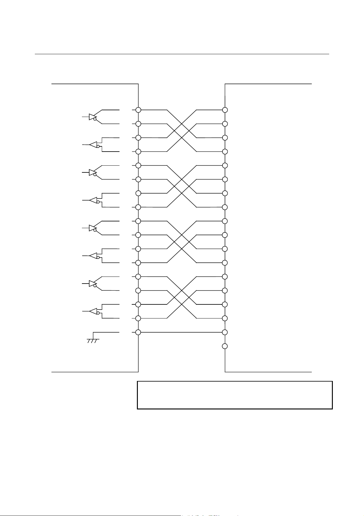
2) General diagram of signal connection
CNC
Output
Input
SD
RD
RS
CS
ER
DR
CD
0V
Host compute r
11
1
15
5
13
3
7
SD
RD
RS
CS
ER
DR
CD
SG
FG Note)
When no CS is used, short-circuit it with the RS. However,
when the protocol A or expansion protocol A is used, perform
connecting as shown in the figure above for use as busy control.
When DR is not used, short-circuit it with ER.
Always short-circuit CD to ER.
NOTE
Connect the FG pin to the FG pin of the relay connector
or to the protective grounding pin inside t he locker.
-8-
Page 15

B-63322EN-1/01 3. ELECTRICAL INTERFACE
3) Signal description
Signal
name
SD 103 Output Send data
RD 104 Input Receive data
RS 105 Output Request to send
CS 106 Input Clear to send
DR 107 Input Data set ready
ER 108.2 Output Data terminal ready
CD 109 Input Received line signal detector
SG 102 Grounding for signal
FG 101 Grounding for protection
RS-232-C
circuit
number
Input/
output
It is used to inform whether the remote buffer is ready to receive data or not.
When the ER signal is on and this signal is on, the remote buffer is ready to
receive data.
It is used to know the busy status at the host computer. When the DR signal
is on and this signal is on, the host computer is regarded as being ready to
receive data.
When this signal is on, it is considered that the preparation at the host
computer has been completed. Generally, it is connected to the ER signal of
the host computer. When this signal is off during data transmission, an
alarm occurs.
Always connect it to the ER signal of CNC side when this signal is not used.
When this signal is on, it is considered that the remote buffer is in ready
condition.
In general, it is connected to the ER signal at the host computer. If it is
turned off during transmission of data, an alarm occurs. If this signal is not
used, always connect this to the ER signal at the CNC side.
This signal is not used for connection to the host computer. Thus, connect it
to the ER signal of remote buffer side.
Description
See “3.1” for the bit configuration.
NOTE
Turn on or off signal according to the following:
-3 V or less +3 V or more
Function OFF ON
Signal Condition Marking Spacing
-9-
Page 16

3. ELECTRICAL INTERFACE B-63322EN-1/01
3.3
RS-422 INTERFACE
remote buffer board
CNC
JD6L
(PCR-E20LMDETZ-SL)
1 RD
2 *RD
3 RT
4 *RT
5 CS
6 *CS
7 RR
8 0V
9 *RR
10 (+24V )
11 SD
12 *SD
13 TT
14 *TT
15 RS
16 *RS
17 TR
18 *TR
19 (+24V)
20
1) Connection between devices
Host compute r (e xample)
1 FG
20
2
21
3
22 *SD
4 SD
23
5
24 *RD
6 RD
25 *RS
7 RS
26 *RT
8 RT
27 *CS
9 CS
28
10
29 *RR
11 RR
30 *TR
12 TR
31
13
32
14
33
15
34
16
35 *TT
17 TT
36
18
37
19 SG
NOTE
Do not connect anything to the (+24V) pin.
-10-
Page 17
B-63322EN-1/01 3. ELECTRICAL INTERFACE
2) General diagram of signal connection
CNC
Output
Input
SD
*SD
RD
*RD
RS
*RS
CS
*CS
TR
*TR
RR
*RR
TT
*TT
RT
*RT
0V
11
12
15
16
17
18
13
14
Host compute r
SD
*SD
1
RD
2
*RD
RS
*RS
5
CS
6
7
9
3
4
8
*CS
TR
*TR
RR
*RR
TT
*TT
RT
*RT
SG
FG Note)
NOTE
Connect the FG pin to the FG pin of the relay connector
or to the protective grounding pin inside t he locker.
-11-
Page 18
3. ELECTRICAL INTERFACE B-63322EN-1/01
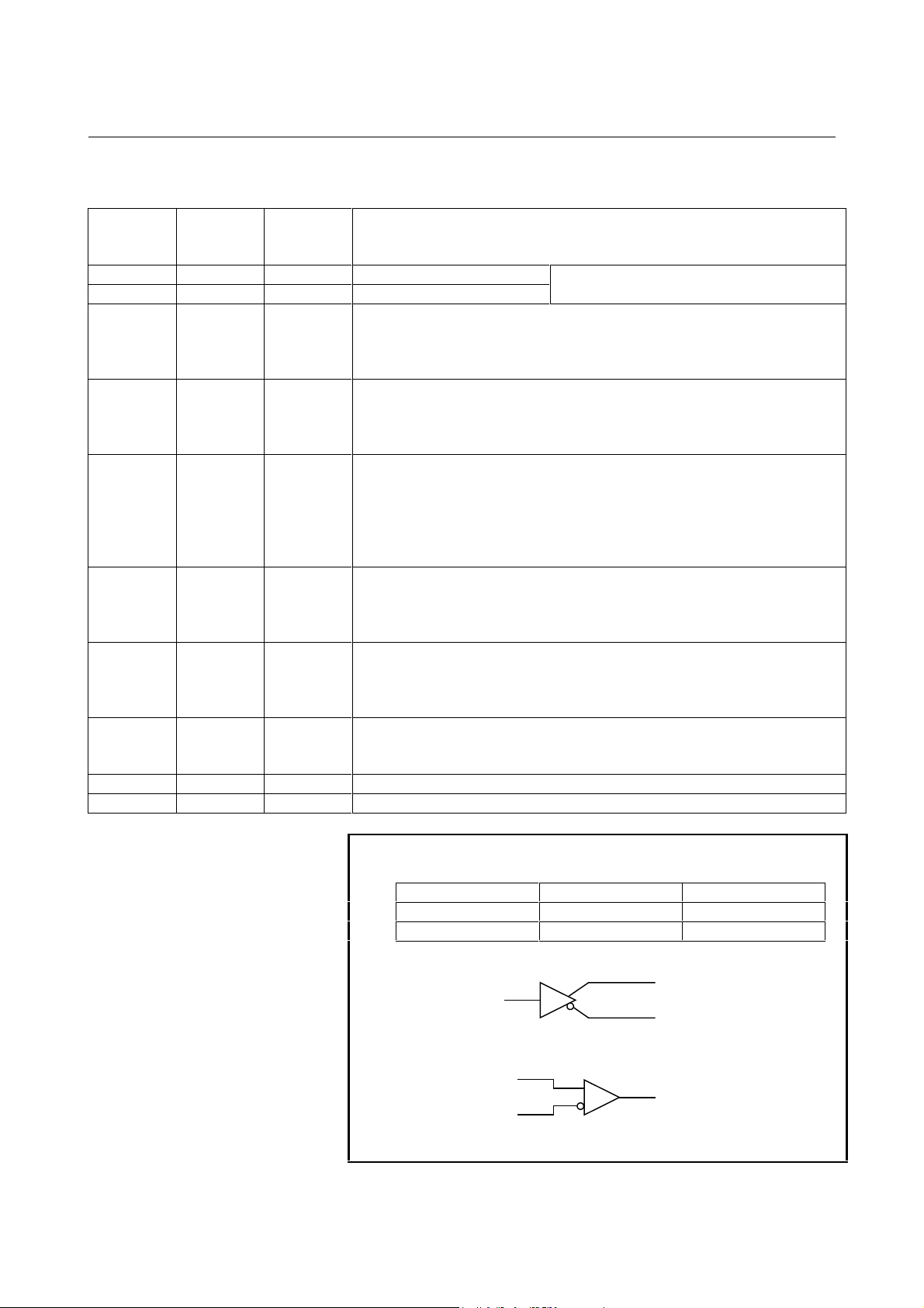
3) Signal description
Signal
name
SD 103 Output Transmission data
RD 104 Input Reception data
RS 105 Output Transmission request
CS 106 Input Clear to send
TR
(ER)
RR
(DR)
TT 113 Output Transmission timing
RT 115 Input Reception timing
SG 102 Grounding for signal
FG 101 Grounding for protection
RS-232-C
circuit
number
108.2 Output Terminal Ready
109 Input Receiver Ready
Input/
output
It is used to inform whether the remote buffer is ready to receive data or not.
When the TR signal is on and this signal is on, the remote buffer is ready to
receive data.
It is used to know the busy status at the host computer. When the RR signal
is on and this signal is on, the host computer is regarded as being ready to
receive data.
When this signal is on, it is considered that the operation of remote buffer
has been completed.
In general, it is connected to the ER signal at the host computer. If it is
turned off during transmission of data, an alarm results. If this signal is not
used, always connect this to the ER signal at the CNC side.
When this signal is on, it indicates that the host computer is ready to transmit
data to the remote buffer. If this signal is not used, always connect it to the
TR signal at the remote buffer side.
Transmission clock transmission terminal at the remote buffer side. When
38400 baud or more is used, always connect it to the RT signal at the host
computer side.
Reception clock input terminal at the remote buffer side. When 38400 baud
or more is used, always connect it to the TT signal at the host computer side.
Description
See “3.1” for the bit configuration.
NOTE
The signal turn on/of f according to the following:
A < B A > B
Function OFF ON
Signal Condition Marking Spacing
Driver
Receiver
A
B
A
B
-12-
Page 19

B-63322EN-1/01 4. PROTOCOL A
4 PROTOCOL A
It is used for the handshake system where the communication between
the remote buffer and host computer repeats transmission/reception
each other.
-13-
Page 20
4. PROTOCOL A B-63322EN-1/01
4.1
MESSAGE FORMAT
The information (character-string) exchanged between the remote
buffer and host computer is called “message”. The general type of
message is shown as below:
Message
Variable length (it can be omitted.)3 byte2 byte
/
Sum Command Data part
/
Field
Checksum 2 No It is used to indicate the lower 8 bits of binary sum of all
Command 3 No It is used to display the type of message (functions) and
Data 0 – n Yes It is the data part corresponding to a command.
End code
(ETX)
Byte
length
Abbreviation Meaning Remarks
bytes from the command field to end code by two-digit
hexadecimal number (0 – 9 and A – F).
to specify the operation and response of the partner.
Abbreviate it when a command without data part is used.
Details are described later.
1 No It indicates the end of message. Not transmit a code
which is the same as an end code to data part.
1 byte
ETX
Transmit the MSB
before the LSB.
SAT, SET, DAT, RTY
SDI, SDO
4.2
CODE SYSTEM
The communication codes between the remote buffer and host
computer are described below:
Field Command Code
Checksum --- ISO/ASCII 5000#2
Command name --- ISO/ASCII 5000#2
DAT ISO/ASCII/EIA/Bin 0000#2Data part
Commands other
than DAT
ISO/ASCII 5000#2
ISO/ASCII 5000#2End code --CR/ETX 5000#3
Related
parameters
-14-
Page 21
B-63322EN-1/01 4. PROTOCOL A
4.3
COMMUNICATION SYSTEM
It is used to perform communication between the remote buffer and
host computer. When the both are ready to operate after power on,
the communication starts from the transmission of remote buffer and
reception of host computer and then the transmission/reception is
repeated.
ER
RS
CS
SD
RD
Approximately 2 seconds
t1 > ti
n1 < 3
SD
CS
RS
RD
n2t2 t3
0 < t2 < To n2 < No
Tx<t3<tp
(1) Approximately two seconds are required for the first request
after both of remote buffer and host computer are ready.
However, when the CS signal is off, the first transmission is
performed after turning on the CS signal.
(2) The minimum time period between bytes is determined by the
parameter Ti (msec) of SET command. There is no prescription
of minimum time period between reception bytes.
(3) Switching from transmission to reception
Immediately the remote buffer side can be ready to receive
signal. Start transmission within the parameter setting time (To
sec) at the host computer side. When no response is obtained for
the time period (To or more), an error occurs in the host
computer. (Overtime)
-15-
Page 22

4. PROTOCOL A B-63322EN-1/01
(4) Switching from reception to transmission
The remote buffer waits for Tx msec (parameter setting time)
and moves to the transmission process after completion of
reception. When there is no transmission after waiting another
parameter (Tp seconds), it is considered that an error occurred in
the remote buffer.
(5) Overrun on reception
When the RS signal is turned off by the remote buffer on
reception of signal, stop the transmission within the overrun
parameter number bytes by the host computer.
(6) Overrun on transmission
When the CS is turned off on transmission of remote buffer, the
transmission is suspended within 3 bytes including that which is
currently being transmitted.
-16-
Page 23

B-63322EN-1/01 4. PROTOCOL A
4.4
4.4.1
COMMAND
Command Table
Commands used in the protocol A are described below:
Origin station R: Remote buffer H: Hoast computer
Command
RDY
RST R Notice of CNC reset
ARS H Response corresponding to the RST Meaningless
ALM R Notice of CNC alarm occurrence
AAL H Response corresponding to the ALM Meaningless
SAT R Notice of remote buffer status
SET H Response corresponding to the SAT
GTD R Transmit command of NC data
DAT H Response corresponding to the GTD
WAT H Response corresponding tot he GTD
Origin
station
R Initialization command
It is used to command the initialization of host.
H Response of SYN
Response when the initialization does not end yet
Initialization command
It is command to initialize the remote buffer.
R Notice of initialization end
The host should respond the RDY in the case of end
of initialization or the SYN when the initialization has
not ended.
H Notice of initialization end
It is used to notice that the initialization of host has
ended.
Immediately after the CNC is res et, transmit this
command when it is possible to transmit signal.
When an alarm occurs in CNC, trans mit this
command when it is possible to transmit immediately
after that.
It is used to notice the status of remote buffer by
transmitting it when there is no data to be especially
transmitted while the Tp sec has passed after
receiving the command.
It is used to modify the setting parameter of remote
buffer by specifying the data part.
Transmit this command when the space of remote
buffer exceeds Nb bytes of parameter setting value
in the remote operation status.
Transmit this command with the NC data.
Transmit this command if the NC data cannot be
transmitted within To when the GTD has been
received.
The GTD is transmitted again by the remote buffer
after a parameter setting time of Tw.
Functions Data part
Meaningless SYNSYN
Meaningless
Meaningless RDY, SYN
Meaningless
Meaningless ARS
Meaningless AAL
Status SET......... Normal
Modification
parameter
Meaningless DAT ........ Normal
NC data
Meaningless
Executed command
at CNC side
CLB
RDI
SDO
SYN
EOB........ End
WAT ....... Busy
RDI
SDO
-17-
Page 24

4. PROTOCOL A B-63322EN-1/01
Command
EOD H Response corresponding to GTD
CLB H Buffer clear
RDI H DI reading request
SDI R Notice of DI
SDO H DO output request
RTY R/H Request of retransmission
Origin
station
Transmit this command when the GTD has been
received while the transmission of NC data has
been completed.
It can be transmitted as the response of SAT when
the buffer at the remote buffer side is to be cleared.
It is used to request transmission of image of
specified 8-bit DI.
The DI image at that time is responded by the SDI
command in the remote buffer.
This command can be transmitted as responses of
SAT and GTD.
It is used to transmit the signal status of DI as the
response of RDI command.
The host should transmit the response of command
received immediately before transmitting the RDI
after receiving this command.
It is used to command that the 8-bit image of data
part should be output to the DO.
It can be transmitted as responses of SAT, GTD,
and SDI.
It is used to request the retransmission of the same
message as before.
Immediately transmit this command when a
transmit error is detected during reception of
messages.
Functions Data part
Executed command
at CNC side
Meaningless
Meaningless
Meaningless
DI image Response
corresponding to the
GTD/SAT
DO image
Reason for
retransmission
Command
transmitted
immediately before
-18-
Page 25

B-63322EN-1/01 4. PROTOCOL A
4.4.2
Description of Data Part
Data part of message is of variable length. Up to 4096 and 72 bytes
can be received/transmitted in the case of <DAT> and the others,
respectively.
1) Data part of SAT
Byte
position
1 Switching of remote/tape operations
According to parameter (Data No. 5000, #1)
setting. (*C)
2 Status of remote buffer
0: Non-completion status of operation
1: Reset status
2: Operation status
3: Alarm status
4: Open line
3 Causes of shift to alarm status
0: NC alarm
1: Checksum error (retry over)
6: Reception of unexpected response
A: Overrun error (retry over)
4 Not used ---
5 - 8 Number of bytes currently stored in the buffer
(Four-digit hexadecimal number)
9 - 12 Current value of parameter Nb
Empty area limit of buffer
(Four-digit hexadecimal number)
13 - 16 Current value of parameter No
Amount of maximum overrun on reception
(Four-digit hexadecimal number)
17 - 20 Current value of parameter No
Number of times of retry on detecting a
transmission error (Four-digit hexadecimal
number)
21 - 24 Current value of parameter Tp
Polling time interval (second)
(Four-digit hexadecimal number)
25 - 28 Current value of parameter To
Time-out time (second)
(Four-digit hexadecimal number)
29 - 32 Current value of parameter Ti
Minimum time interval between bytes
transmitted (Four-digit hexadecimal number)
33 - 36 Current value of parameter Tx
Minimum switching time from reception to
transmission (Four-digit hexadecimal number)
37 - 40 Current value of parameter Tw
Waiting time on reception of (WAT)
(Four-digit hexadecimal number)
Meaning and code
preparation
(command error)
Default value
(hexadecimal)
0
0
0
0000
07D0
0032
000A
0005
0014
000A
0064
0005
-19-
Page 26
4. PROTOCOL A B-63322EN-1/01
2
Byte
position
41 - 44 Unit for the boring time (four digits in
hexadecimal)
Setting parameter P
boring time to 0.1 seconds.
15 0
0000000000000P
45 - 46 Note)
Code to be converted (two-digit hexadecimal
number)
47 - 78 Note)
Code after conversion (two-digit hexadecimal
number)
49 - 54 Rese rve --55 - 56 Packet length parameter n of expansion
protocol A (two-digit hexadecimal number)
00: Normal protocol A
01: Expansion protocol A
02: Expansion protocol A
04: Expansion protocol A
57 - 72 Not used ---
Meaning and code
to 1 sets the unit for the
2
00
NC data length = 256 bytes
Packet length = 260 bytes
NC data length = 512 bytes
Packet length = 516 bytes
NC data length = 1024 bytes
Packet length = 1028 bytes
Default value
(hexadecimal)
0000
00
00
00
NOTE
Bytes 45, 46, 47, and 48 of SAT
These bytes contain the parameters necessary for the
remote buffer t o convert the protocol A <DAT > command
data and expansion protocol A data in the specified
section. Specify the code to be converted in bytes 45
and 46. Specify the code to which conversion is to be
performed in bytes 47 and 48. For details, refer to
Section 4.4.2 (3).
-20-
Page 27

B-63322EN-1/01 4. PROTOCOL A
a) Protocol A
Section to be converted
//
SUM
DAT
Data
//
ETX
b) Expansion protocol A
Section to be converted
//
Data
//
No
ETXSUM
<Example of use>
The host computer handles an EOB code in an NC program as “;” and
transmits it to the CNC as is. When ‘3’ and ‘B’ (= 3BH) are specified
in SET command bytes 45 and 46, and ‘ ’ and ‘A’ (= 0AH) are
specified in bytes 47 and 48, “;” is converted to “LF” which is then
transmitted to the CNC.
2) Data part of SET
The format of data part of command <SET> is the same as that
of data part of <SAT> except the following points.
Data part can be abbreviated when no parameter is modified.
Byte
position
1 Switching request of remote/tape operations
2 Status of host computer Ignore
3 - 8 Not used
9 - 48 Modified value of parameter
49 - 54 Not used
55 - 56 Parameter for expansion protocol
57 - 72 Not used
Meaning and code Remarks
3) Data part of DAT
Up to 4096 bytes of NC data can be received at the data part of
command <DAT>.
Transmit the NC data depending on the specifications of NC
since no data process is performed in the remote buffer other
than the conversion code set by the parameter.
Also, always add the EOR code to the end of NC program.
-21-
Page 28

4. PROTOCOL A B-63322EN-1/01
4) Data part of SDI
Byte
position
1 - 2 2-byte hexadecimal display of 8-bit contents of DI
(PMC address: G152)
3 - 72 Not used (it can be omitted.)
Meaning
1) Data part of SDO
Byte
position
1 - 2 2-byte hexadecimal display of 8-bit contents of DO
(PMC address: F152)
3 - 72 Not used (it can be omitted.)
Meaning
6) Data part of RTY
Byte
position
1 Reason for requesting retransmission
1: Checksum error
3: Overrun error (Data received after RS has been turned off)
2 - 72 Not used (it can be omitted.)
Meaning
7) Data part of other commands
Byte
position
1 - 72 Not used (it is generally omitted.)
Meaning
-22-
Page 29

B-63322EN-1/01 4. PROTOCOL A
4.5
PARAMETER TABLE
Parameters which can be set in the data part of SET command are
shown as below:
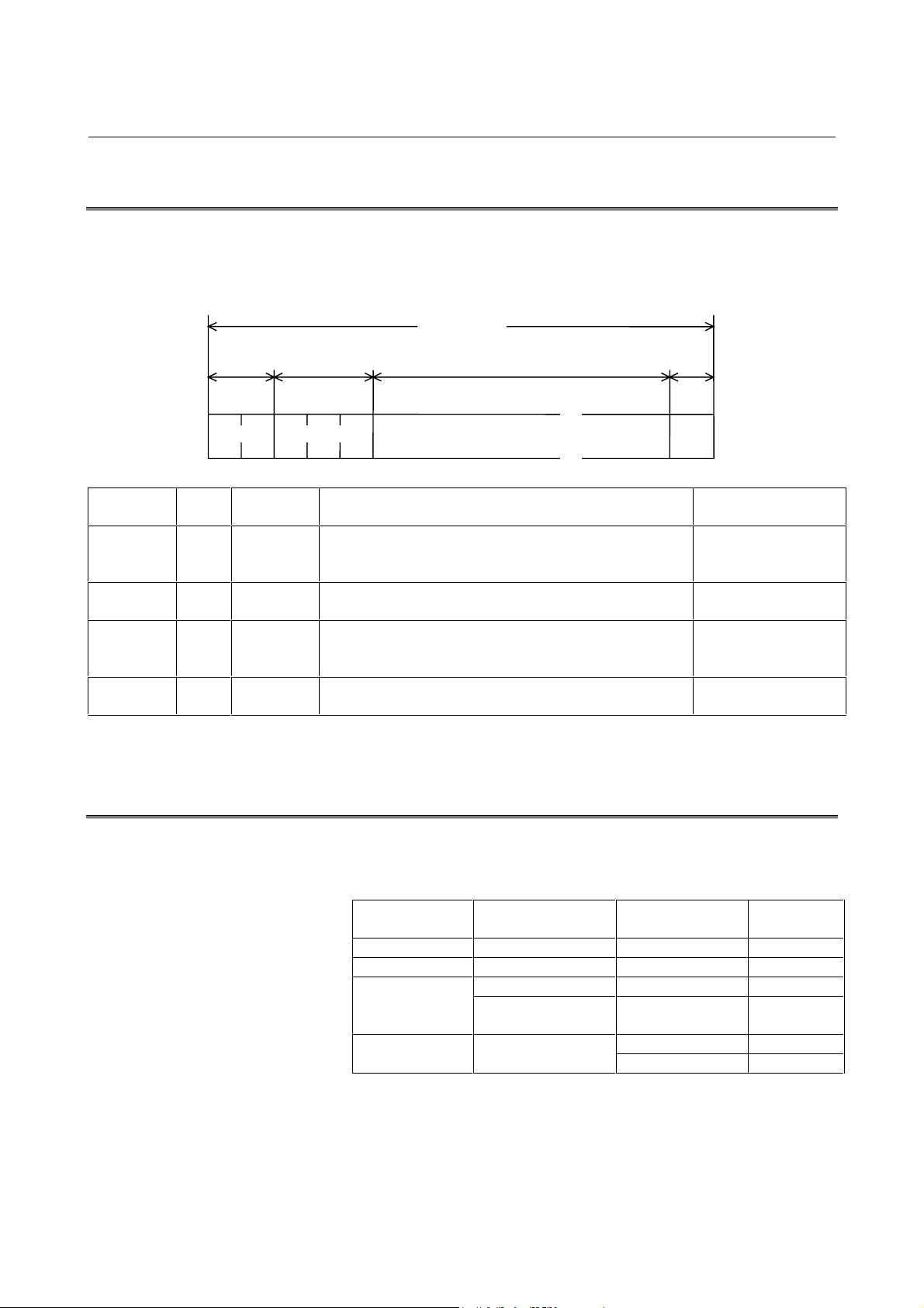
Parameter Meaning Unit Range
Nb Number of bytes of minimum buffer empty area on transmission of
GTD
(Note 1)
No Maximum amount of overrun on reception of data Byte 2 - 2000 50
Ne Number of retry times on detection of transmission error Times 0 - 100 10
Tp Polling time interval Sec 1 - 99 5
To Time-out time Sec 1 - 999 20
Ti Minimum time interval between transmission bytes msec 0 - 10
Tx Minimum switching time from reception to transmission msec 0 - 100 100
Tw Wait time on reception of WAT Sec 0 - Tp 5
Byte 1 - 4000 2000
(Note 2)
NOTE
1 Setting value l+No≤Nb≤4000 (l : Data length for DAT
command)
2 2 msec step
On turning
on power
10
-23-
Page 30

4. PROTOCOL A B-63322EN-1/01
4.6
ERROR PROCESS
1) Open-line error
When the following error occurs, it may be an open line error.
Restart the initialization of remote buffer for recovering the line.
When the line is recovered, it waits for transmission of SYN and
is SYN wait status.
The procedures are the same as those of initialization on power
on other than continuation or SYN of host computer.
(1) Framing error
(2) Overrun error
(3) Parity error
(4) Data Set Ready off
(5) Buffer full (the transmission stop request is unacceptable.)
(6) Time out
(7) Number of retry times has been exceeded.
2) Reception error
Ignore the reception data and restart the reception of SAT
command at the remote buffer side when the following errors
occurs.
(1) Number of retry times exceeded
Number of RTY reception times + Number of
retransmission by checksum error > Ne
(2) Command error
Message format error
Reception of undefined command
Reception of unexpected command
(3) Overrun
This results if the transmission stop request is not accepted
and the reception buffer is overflown.
3) Reception during transmission
Data received during transmission is ignored.
-24-
Page 31

B-63322EN-1/01 4. PROTOCOL A
4.7
STATUS TRANSITION
The status transition diagram of remote buffer is shown as below:
Turning on power
Non-completed status of
operation preparation
SYN
reception
NC reset
EOD reception
0
Reset status
1
RDY reception
GTD
transmission
Line error Note 1
Reception error
NC alarm
Line error
After 2 msec
Open line status
4
NC reset
Line error
(Note 1)
Remote operation
status
2
Reception error
NC alarm (Note 2)
NOTE
1 Causes of line error
(1) DR off
(2) Number of retry times over
(3) Time out
(4) Buffer full
2 Reception error
(1) Undefined command
(2) Unexpected command
(3) Number of retry times over by sum error
(4) Overrun
Alarm status
3
-25-
Page 32

5. EXPANSION PROTOCOL A B-63322EN-1/01
5 EXPANSION PROTOCOL A
It allows the NC data between the remote buffer and host computer to
be efficiently transferred by adding the high-speed reception function
to the protocol A.
-26-
Page 33

B-63322EN-1/01 5. EXPANSION PROTOCOL A
5.1
COMMUNICATION SYSTEM
The expansion protocol A is the same as the protocol A excluding the
transmission of NC data.
The expansion protocol A mode is initiated after the <GTD> is output
to the host computer by the remote buffer according to the data
request from the CNC side.
The communication system is performed in the full duplex mode in
the expansion protocol A. The NC data transmitted is packeted and is
transmitted to the remote buffer by the host computer. Also, perform
the reception process of monitor packet from the remote buffer.
GTD transmission
Protocol
A
mode
End packet
Mode transition
Expansion
protocol A
mode
Packet transmission/
reception
-27-
Page 34

5. EXPANSION PROTOCOL A B-63322EN-1/01
5.2
DATA PACKET FORMAT
The NC data is transferred to the remote buffer using the following
format by the host computer after receiving the <GTD>.
When the NC data transmitted becomes multiple packets, the packets
can be transmitted in order without waiting the response from the
remote buffer by the host computer.
NC data
( "256*n" byte )
Calculation range of checksum
1) NC data
The NC data is the fixed length of “256*n” bytes and the n is
specified with the parameter (byte position 55 to 56) by the
<SET> command.
The default value of n is 0. In the case of “n = 0”, the normal
protocol A is used.
n = 0 : Normal protocol A
n = 1, 2, 4 : Expansion protocol A
Packet
No.
(1 byte)
Checksum
(2 byte)
End code
(1 byte)
NOTE
Note that n is set to 0 automatically even if n is set to t he
values other than listed above.
2) Packet No.
a) Effective packet : 30h – 39h (ASCII code)
Be sure to assign packet No. 30h to the first packet. If there
is only one effective packet, assign FFh to the packet, since
it is not only the first but also the last packet.
If there is more than one effective packet, packet No. 30h is
transmitted to the host computer by the remote buffer, along
with the monitor packet <NAK> of retransfer request.
Hereafter, the value incremented by 1 should be the packet
No.
However, the value next to 39h becomes 30h.
If there is only one packet, the packet is both the first and
the last; be sure to assign FFh.
Also, when the loss or improper order of packet No. is
detected, the improper packet No. is transmitted to the host
computer along with the monitor packet No. <NAK>.
When the checksum error is detected, the improper packet
No. is transmitted to the host computer with the monitor
packet <NAK> of retransfer request by the remote buffer.
-28-
Page 35

B-63322EN-1/01 5. EXPANSION PROTOCOL A
b) End packet : FFh
The end packet is transmitted by setting the packet No. to
FFh. The data part of end packet is considered to be the
effective data. However, the end packet received after
transmitting <CAN> ignores the data part.
This allows the expansion protocol A mode to be ended and
the normal protocol A mode is initiated.
However, when the checksum error is detected at the end
packet, the before packet No. +1 is transmitted as the end
packet No. to the host computer with monitor packet
<NAK> of retransmission request. (Note)
The host computer should shift to the protocol A when the
command of protocol A is received after transmitting the
end packet.
NOTE
If FFh is assigned to the first packet, packet No. 0 is
transmitted to the host computer with <NAK>, since this
packet is the last packet.
c) Invalid packet : Other than above
Transmit this invalid packet with the dummy data of
“256*n” bytes when the time out may occur since time is
required for editing of NC data transmitted by the host
computer.
The remote buffer is processed as an invalid packet.
3) Checksum
The checksum is obtained by adding the NC data to the packet
No. in units of byte and then expressing the 1 byte data produced
by neglecting the overflow above 8 bits out of the total value
above using ASCII 2-byte code.
4) End code
The end code should be the ASCII code CR (0Dh).
-29-
Page 36

5. EXPANSION PROTOCOL A B-63322EN-1/01
5.3
MONITOR PACKET FORMAT
The monitor packets transmitted from the remote buffer to the host
computer are shown as below. All packets have the fixed length
consisting of 5 bytes.
1) Stop request
CAN
(18h )
The stop request is transmitted to the host computer by the
remote buffer when resetting the NC and stopping data reception
by an alarm.
Transmit the end packet (the NC is dummy) after transmitting
the packet which is currently being transmitted and move to the
normal protocol A mode when this packet is received by the host
computer.
If the end packet was being transmitted when the CAN packet
was received, the end packet need not be retransmitted in
response to CAN.
Transmit the end packet even in the DC3 reception status.
Meaningless
(20h )
Checksum
( 2 b y t e )
End code
( 0Dh )
2) Retransmission request
NAK
( 15h )
Packet No.
(1 byte)
Checksum
( 2 b y t e )
When a check sum error is detected in the received packet, the
retransmission request corresponding to the packet is transmitted
by the remote buffer.
The host computer should perform retransmission from the
corresponding packet immediately after ending the transmission
of packet which is currently being transmitted when it receives
this packet.
End Code
(0Dh )
-30-
Page 37

B-63322EN-1/01 5. EXPANSION PROTOCOL A
3) Interruption request
DC3
(93h )
Meaningless
( 20h )
Checksum
( 2 b y t e )
The interruption request is transmitted to the host computer by
the remote buffer when the reception buffer may become
overflown.
The host computer should interrupt the transmission and wait
until the next monitor packet is received after completing the
transmission of packet which is currently being transmitted when
it receives this packet.
4) Restart request
DC1
( 11h )
Meaningless
( 20h )
Checksum
( 2 b y t e )
The restart request is transmitted to the host computer by the
remote buffer when there is space in the reception buffer after
requesting interruption.
The host computer should restart the transmission from the next
packet following the interrupted one when this packet is
received.
End code
(0Dh )
End code
(0Dh )
-31-
Page 38

5. EXPANSION PROTOCOL A B-63322EN-1/01
5.4
COMMUNICATION EXAMPLE
1) Normal
Remote buffer
<
G
T
D
>
)
0
(
t
e
k
c
a
P
)
1
(
t
e
k
c
a
P
)
2
(
t
e
k
c
a
P
)
3
(
t
e
k
c
a
P
Host computer
)
h
F
F
0
(
t
e
k
c
a
p
d
n
E
<
S
A
T
>
>
T
E
S
<
-32-
Page 39

B-63322EN-1/01 5. EXPANSION PROTOCOL A
2) Stop request
Remote buffer
RESET
Host computer
<
G
T
D
>
)
0
(
t
e
k
c
a
P
)
1
(
t
e
k
c
a
P
)
2
(
et
k
c
a
P
"
C
A
N
"
)
h
F
F
0
(
t
e
k
ac
P
d
n
E
m
u
D
(
)
a
t
a
d
y
m
<
R
S
T
>
>
S
R
A
<
<
S
A
T
>
>
T
E
S
<
-33-
Page 40

5. EXPANSION PROTOCOL A B-63322EN-1/01
3) Retransmission (i)
Remote buffer
Checksum error
detection
Host computer
<
G
T
D
>
)
0
(
t
e
k
c
a
P
)
1
(
t
e
k
c
a
P
)
2
(
t
e
k
c
a
P
"
N
A
K
"
(
1
)
)
1
(
t
e
k
c
a
P
)
2
(
t
e
k
c
a
P
)
3
(
t
e
k
c
a
P
)
h
F
F
0
(
t
e
k
c
a
p
d
n
E
Retransmit from
the packet (1)
<
S
A
T
>
>
T
E
S
<
-34-
Page 41

B-63322EN-1/01 5. EXPANSION PROTOCOL A
3) Retransmission (ii)
Remote buffer
Checksum error
detection
Host computer
<
G
T
D
>
)
0
(
t
e
k
c
a
P
)
1
(
t
e
k
c
a
P
)
2
(
t
e
k
c
a
P
)
3
(
t
e
k
c
a
P
)
h
F
F
0
(
t
e
k
ac
P
d
n
E
"
N
A
K
"
(
4
)
)
h
F
F
0
(
t
e
k
c
a
P
d
n
E
<
S
A
T
>
>
T
E
S
<
-35-
Page 42

5. EXPANSION PROTOCOL A B-63322EN-1/01
3) Retransmission (iii)
Remote buffer
Packet No.
Out-of-order
detection
Packet No.
Out-of-order
detection
Host computer
<
G
T
D
>
)
1
(
t
e
k
c
a
P
)
2
(
t
e
k
c
a
P
"
N
A
K
"
(
0
)
)
0
(
t
e
k
c
a
P
)
1
(
t
e
k
c
a
P
)
3
(
t
e
k
c
a
P
)
h
F
F
0
(
t
e
k
c
a
p
d
n
E
"
N
A
K
"
(
2
)
)
2
(
t
e
k
c
a
P
)
3
(
t
e
k
c
a
P
)
h
F
F
0
(
t
e
k
c
a
p
d
n
E
<
S
A
T
>
>
T
E
S
<
-36-
Page 43

B-63322EN-1/01 5. EXPANSION PROTOCOL A
4) Interruption → Restart
Remote buffer
Empty buffer
Remaining
less than
2 Packet s
Empty buffer
Remaining
more than
3 Packet s
Host computer
<
G
T
D
>
)
0
(
t
e
k
c
a
P
)
1
(
t
e
k
c
a
P
)
2
(
t
e
k
c
a
P
)
3
(
t
e
k
c
a
P
"
D
C
3
"
"
D
C
1
"
)
h
F
F
0
(
t
e
k
c
a
P
d
n
E
<
S
A
T
>
>
T
E
S
<
-37-
Page 44

5. EXPANSION PROTOCOL A B-63322EN-1/01
5) Interruption → Start
Remote buffer
Empty buffer
Remaining
one block
RESET
Host computer
<
G
T
D
>
)
0
(
t
e
k
c
a
P
)
1
(
t
e
k
c
a
P
)
3
(
t
e
k
c
a
P
"
D
C
3
"
"
C
A
N
"
)
H
F
F
0
(
t
e
k
ac
P
nd
E
m
u
D
(
)
a
t
a
d
y
m
Transmit the end
packet for ending
the expansion
protocol A although
the DC3 is
currently being
received.
<
R
S
T
< ARS >
<
S
A
T
T
E
S
<
>
>
>
-38-
Page 45

B-63322EN-1/01 5. EXPANSION PROTOCOL A
6) Interruption → Retransmission
Remote buffer
Empty buffer
Remaining
one block
Checksum error
detection
Empty buffer
Remaining
two blocks
Host computer
<
G
T
D
>
)
0
(
t
e
k
c
a
P
)
1
(
t
e
k
c
a
P
"
D
C
3
"
)
2
(
t
e
k
c
a
P
"
N
A
K
"
(
2
)
)
2
(
t
e
k
c
a
P
Transmit only an
error packet since
the DC3 is receiving
data.
Restart transmission
of packets following
this after receiving
DC1.
"
D
C
1
"
)
3
(
t
e
k
c
a
P
)
h
F
F
0
(
t
e
k
c
a
P
d
n
E
<
S
A
T
>
>
T
E
S
<
-39-
Page 46

5. EXPANSION PROTOCOL A B-63322EN-1/01
7) Time-out detection
Remote buffer
Time-out
detection
Host computer
<
G
T
D
>
)
0
(
t
e
k
c
a
P
<
S
Y
N
>
>
N
Y
S
<
<
R
D
Y
>
>
Y
D
R
<
<
S
A
T
>
>
T
E
S
<
NOTE
The time-out monitoring period lasts until the next one
packet is received immediately after output of <GTD>.
After that, it is t he time between reception of one pack et
and that of another.
-40-
Page 47

B-63322EN-1/01 6. PROTOCOL B
6 PROTOCOL B
The protocol B is used to control the communication between the
remote buffer and host computer by the control code.
-41-
Page 48

6. PROTOCOL B B-63322EN-1/01
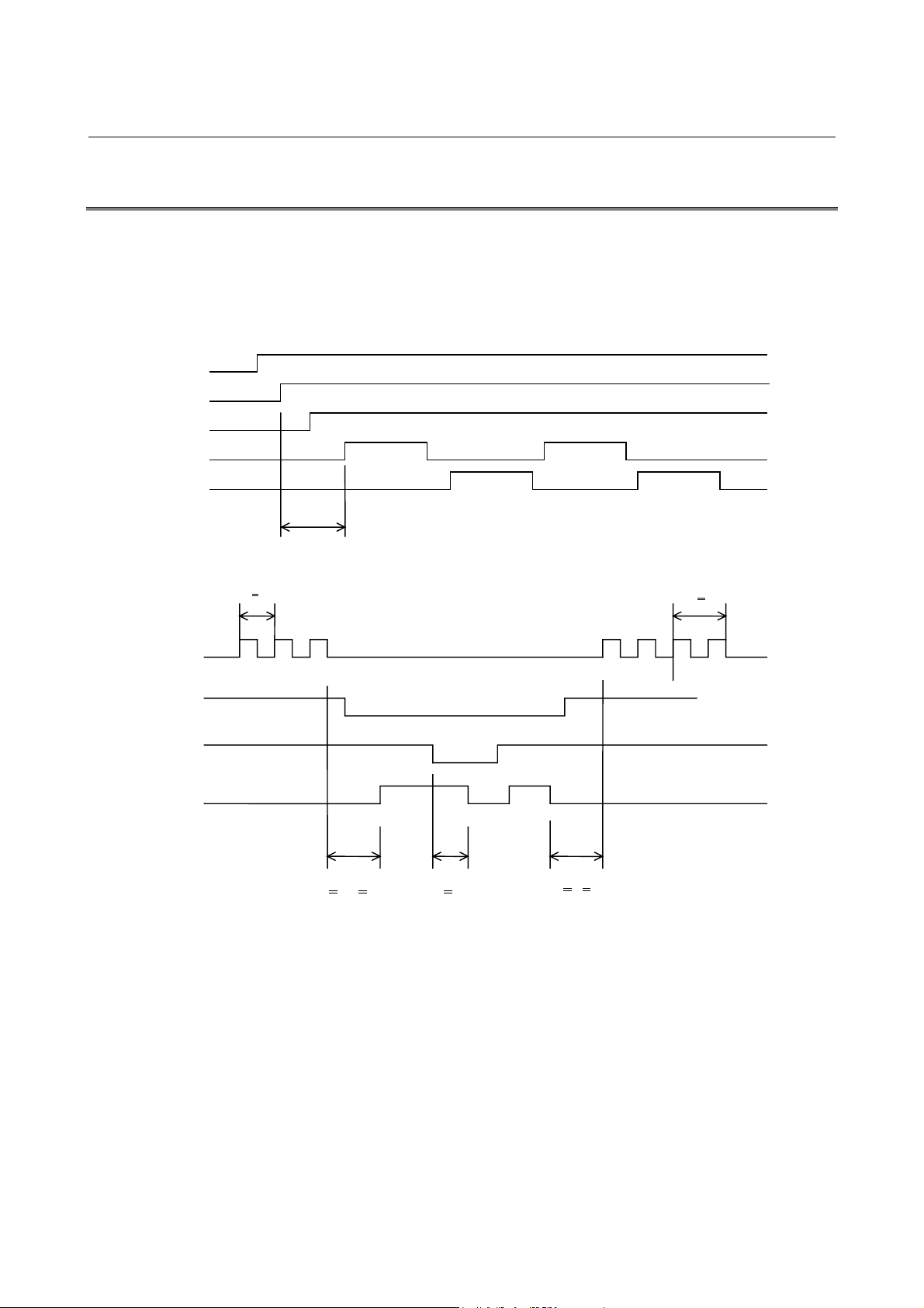
6.1
6.1.1
ER (output)
RS (output)
SD (output)
COMMUNICATION SYSTEM
The communication system can be in either of two settings, one in
which the CNC reset/alarm state is posted to the host and the other in
which it is not posted. When ETX (bit 3 of parameter No. 5000) is 1,
the system is in the setting in which the state is posted.
When the CNC Alarm/Reset is not Posted to the Host
1) When the remote buffer receives data
The remote buffer requests the host computer to send data.
10 ms or more 100 ms or more
DC3DC1DC3DC1
ER code
RD (input)
DR (input)
CS (input)
Overrun
1 ms or more
(1) The remote buffer transmits the DC1 code.
(2) The host computer starts to transmit the DC3 code to the
remote buffer by the DC1 code.
(3) When the empty area of remote buffer area becomes the
value specified, the DC3 code is transmitted.
(4) T he host computer should stop transmission to the remote
buffer by the DC3 code. The overrun value is specified
later.
(5) The remote buffer transmits the DC1 code when the
remainder of buffer data becomes less than the level
specified and requests the host computer to start
transmitting data.
(6) The host computer should start transmitting data again by
the DC1 code. The transmission data is a continuation of
previous data.
-42-
Page 49

B-63322EN-1/01 6. PROTOCOL B
(7) The remote buffer transmits the DC3 code when the data
read is completed. The end of data read is indicated by the
detection of ER or NC reset.
(8) The host computer stops transmission of data.
2) When the remote buffer sends data (punch-out)
(Fig. A)
10 ms or more 100 ms or more
ER (output)
RS (output)
SD (output)
DR (input)
CS (input)
ER (output)
RS (output)
DC4DC2
1 ms or more
2 characters or less
(Fig. B)
10 ms or more 100 ms or more
DC4DC2
SD (output)
RD (input)
DR (input)
CS (input)
DC3 DC1
Overrun
1 ms or more
-43-
Page 50

6. PROTOCOL B B-63322EN-1/01
(1) The remote buffer transmits the DC2 code.
(2) The remote buffer then transmits punch-out information.
(3) If the processing speed of the host computer is not high
enough to handle arriving data, perform one of the
following:
(a) Turn the CS signal of the remote buffer off. The
remote buffer stops data transmission within two
characters including the character being sent. (See Fig.
A.)
(b) Send a DC3 code to the remote buffer. The remote
buffer stops data transmission within the overrun,
which will be explained later, from the point when
DC3 is sent. To make the remote buffer resume data
transmission, send a DC2 code to the remote buffer.
(See Fig. B.)
(4) When the host computer completes data processing, turn
the CS signal of the remove buffer on. Then, the remote
buffer sends the data following the previous data.
(5) When data transmission is completed, the remote buffer
sends the DC4 code.
6.1.2
When the CNC Alarm/Reset is Posted to the Host
When the remote buffer becomes ready after the power is turned on,
the remote buffer turns the ER signal on, and keeps the ER signal on
until the power is turned off. When an alarm occurs in the NC, the
NAK code is sent to the host computer, and when the NC is reset, the
SYN code is sent to the host computer. This is not performed,
however, if the host computer is not ready for reception (each of the
DR, CD, and CS signals is on).
-44-
Page 51

B-63322EN-1/01 6. PROTOCOL B
1) When the remote buffer is neither receiving nor transmitting data
CNC power-on Reset or alarm Reset or alarm Reset or alarm
ER (output)
RS (output)
SD (output)
RD (input)
DR (input)
CD (input)
CS (input)
SYN or NAK
Ignored period Valid period Ignored period
The “SYN” or “NAK” code is output upon reset of the CNC or the
detection of a CNC alarm, but only during the valid period shown in
the above figure.
2) When the remote buffer is receiving or transmitting data
ER (output)
RS (output)
SD (output)
RD (input)
DR (input)
CD (input)
CS (input)
ON
ON
(1)
<When the remote buffer is receiving data>
Reset or alarm
DC1
(2) (4) (6) (8)
(3)
DC3
(5)
DC1
-45-
(7)
DC3
SYN or
NAK
Page 52

6. PROTOCOL B B-63322EN-1/01
(1) The remote buffer transmits the DC1 code.
(2) Upon receiving the DC1 code, the host computer shall start
transmitting data to the remote buffer.
(3) Once the amount of free space in the remote buffer falls below
the specified value, the remote buffer transmits the DC3 code.
(4) Upon receiving the DC3 code, the host computer shall stop
transmitting data to the remote buffer.
(5) Once the amount of data in the remote buffer falls below the
specified value, the remote buffer transmits the DC1 code to
request that the host computer restart data transmission.
(6) Upon receiving the DC1 code, the host computer shall restart
data transmission, picking up from the data immediately after
that transmitted last.
(7) When the CNC has been reset or an alarm has been issued in the
CNC, the remote buffer transmits, to the host computer, the DC3
code, followed by the SYN code (for reset) or NAK code (for an
alarm). Thus, data reading is terminated.
(8) The host computer shall stop data transmission.
<When the remote buffer is transmitting data (punch-out)>
ER (output)
ON
ON
RS (output)
SD (output)
DR (input)
CS (input)
DC2
(1)
(2)
(3)
(Fig. A)
Reset or alarm
DC4
(4)
If a CNC reset or CNC alarm occurs during
this period, DC4
transmitted.
(5)
SYN or
NAK
, SYN, or NAK is not
-46-
Page 53

B-63322EN-1/01 6. PROTOCOL B
(Fig. B)
Reset or alarm
ON
ER (output)
ON
RS (output)
SD (output)
RD (input)
DR (input)
CS (input)
DC2
SYN or
(2)(1)
DC4
DC3 DC1
(4)(3)
(5)
NAK
(1) The remote buffer transmits the DC2 code.
(2) The remote buffer starts transmitting punch-out data.
(3) If data processing in the host computer cannot keep pace with
the rate of data transmission from the remote buffer:
(a) Turning off the CS signal for the remote buffer causes the
remote buffer to stop data transmission after transmitting a
maximum of most two characters, including the character
currently being transmitted. (See Fig. A.)
(b) Transmitting a DC3 code to the remote buffer causes the
remote buffer to stop data transmission, such that the
amount of data transmitted after transmission of the DC3
code does not exceed the overrun. (See Fig. B.)
NOTE
If the RBETX bit of parameter No. 5000 is set to 1,
method (a) cannot be used because, while the CS signal
is off, a SYN/NAK or DC4 code is not transmitted even if
CNC reset or a CNC alarm occurs. In such a cause, use
method (b).
(4) For method (a) in step (3)
Once data processing by the host computer terminates, turning
on the CS signal for the remote buffer causes the remote buffer
to restart data transmission, picking up from the data
immediately after that transmitted last.
For method (b) in step (3)
Transmitting a DC1 code to the remote buffer causes the remote
buffer to restart data transmission.
(5) When the CNC has been reset or an alarm has been issued in the
CNC, the remote buffer transmits, to the host computer, a DC4
code, followed by a SYN code (for reset) or NAK code (for an
alarm).
-47-
Page 54

6. PROTOCOL B B-63322EN-1/01
6.2
6.3
CONTROL CODE
The control code is as shown below regardless of the ISO, EIA, and
Binary data:
Control
code
DC1 Starts host transmission. 11H 11H
DC3 Stops host transmission. 93H 13H
DC2 Starts punch-out. 12H 12H
DC4 Stops punch-out. 14H 14H
NAK Posts an NC alarm. 95H 15H
SYN Posts NC reset. 96H 16H
BUFFER CONTROL
The buffer control method of remote buffer is described in the
following:
Function
Code (hexadecimal)
Bit 2 of parameter
No. 5000 = 0
Bit 2 of parameter
No. 5000 = 1
Protocol Interface MAX baud rate
Protocol B RS-232-C 19200 Remaining characters <=
Expansion
protocol B
RS-422 86400 Remaining characters <=
DC3 transmission
conditions
512 characters
2560 characters
DC1 transmission
conditions
Vacant space >= 4096
characters
Vacant space >= 4096
characters
Allowable
overrun value
Less than 512
characters
Less than 2560
characters
-48-
Page 55

B-63322EN-1/01 6. PROTOCOL B
6.4
ALARM AND RESET OF CNC
Once an alarm has been issued in the CNC, or upon the CNC being
reset, the remote buffer transmits the DC3 code, then:
(1) When the CNC reset/alarm state is not to be posted to the host
(parameter No. 5003 bit 3 = 0)
Turns off the ER signal, then performs close processing.
(2) When the CNC reset/alarm state is to be posted to the host
(parameter No. 5003 bit 3 = 1)
Transmits the “SYN” or “NAK” code to the host, then performs
close processing.
NOTE
1 When the parameter is set to post the CNC reset/alarm
to the host, the CNC term inates comm unication upon the
occurrence of an alarm in the CNC during
communication in either of the following cases:
(1) For foreg r ound oper ation: The reset key or the STOP
key (soft key) is pressed.
(2) For background oper ation: The STOP k ey (soft key)
is pressed. (A reset does not cause communication
to terminate.)
2 When the remote buffer transmits data (for punch-out),
pressing the STOP soft key of the CNC cannot stop the
data transmission until all the buff ered data between the
CNC and remote buffer has been transmitted t o the host
computer.
To stop data transmission immediately, press the RESET
key.
-49-
Page 56

7. EXPANSION PROTOCOL B (RS-422) B-63322EN-1/01
7 EXPANSION PROTOCOL B (RS-422)
The expansion protocol B is a protocol used to enable high-speed
transmission with a simple protocol. The communication system is
the same as that of protocol B.
However, the overrun value after transmission of DC3 is limited to
1280 characters or less to enable high-speed transmission.
* When the remote buffer receives data
TR (output)
RS (output)
DC3DC1
DC1 DC3
SD (output)
RD (input)
RR (input)
CS (input)
TR (output)
RS (output)
SD (output)
DC2
ER code
2560 characters or less 2560 characters or less
* When the remote buffer transmits data
DC4
DC3
DC1
RD (input)
RR (input)
CS (input)
2560 characters or less
-50-
Page 57

B-63322EN-1/01 8. DATA INTERFACE
8 DATA INTERFACE
-51-
Page 58

8. DATA INTERFACE B-63322EN-1/01
8.1
DATA PART
Sum Command
Data received from the host computer is largely classified into two
parts, namely the control part and data part.
With the protocol B/expansion protocol B, all data received from the
host computer become the data part.
See the following figure for the data part of protocol A/expansion
protocol A.
1) Protocol A
Packet configuration of <DAT>
Data partControl part
/
Data
/
ETX
ETX
2) Expansion protocol A
Configuration of response packet for <GTD>
Data part Control part
/
Data
Sum
/
ETXNo.
8.2
INTERFACE OF DATA PART
The interface of data part is in conformity the provisions of data
which can be handled through the serial port by the CNC.
The end of data part is judged by the detection of EOR code. Also,
all data after EOR code is ignored.
In general, the data part configuration is as shown below. However,
in the case of DNC operation, the data already received will be lost by
the CNC reset.
Significant information
% ; Program-1 M02 ; Program-2 M02 ; .... ; Program-N M02 ; %
-52-
Page 59

B-63322EN-1/01 9. BINARY INPUT OPERATION FUNCTION
9 BINARY INPUT OPERATION FUNCTION
-53-
Page 60

9. BINARY INPUT OPERATION FUNCTION B-63322EN-1/01
9.1
FUNCTION EXPLANATION
Once a single "G05;" block is specified in normal NC command
format, operation can be performed by specifying desired move data
and auxiliary functions in the following format.
By specifying zero for all of the travel distances along all axes and the
auxiliary function, the system subsequently accepts commands in
normal NC command format again..
• Binary input operation on: G05;
• Binary input operation off: Zero specified for all of the travel
distances along all axes and the auxiliary function
Host computer
©
RS232Cª or
©
ª
RS422
CNC
(FS15i)
Remote buffer
High
byte
byte
First axis
Low
byte
• Data format for binary input operation
Second axis
High
byte
Order of data items
Low
byte
(1) In this format, the travel distance per unit time along each axis
(2) The unit time in msec can be specified with bits 0, 1, and 2 of
(3) All data must be in binary representation.
Auxiliary function
Fourth
byte
• • •
First
byte
Check
byte
• • •
High
byte
N-th axis
Low
byte
(two bytes) is arranged for all axes, starting with the first axis,
followed by an auxiliary function (four bytes. See (6).) and by
the check byte (one byte).
parameter No. 7618.
-54-
Page 61

B-63322EN-1/01 9. BINARY INPUT OPERATION FUNCTION
(4) The travel distance along each axis must be specified in the
following units. (Negative travel distances must be in two’scomplement form.)
IS_A IS_B IS_C IS_D IS_E Unit
Millimeter
machine
Inch
machine
Rotation
axis
0.01 0.001 0.0001 0.00001 0.000001 mm
0.001 0.0001 0.00001 0.000001 0.0000001 inch
0.01 0.001 0.0001 0.00001 0.000001 deg
(5) The following data formats can be selected for the travel
distance, using RDS (bit 2 of parameter No. 7609). (Specify the
travel distance per unit time using the bits marked with the
asterisk (*).)
• Special format (bit 2 of parameter No. 7609 = 0)
15 14 13 12 11 10 9 8 7 6 5 4 3 2 1 0
*******0*******
0
• General format (bit 2 of parameter No. 7609 = 1)
15 14 13 12 11 10 9 8 7 6 5 4 3 2 1 0
****************
(Example) If the travel distance per unit time is 700 microns
(Millimeter machine, unit: IS_B.)
• Special format (bit 2 of parameter No. 7609 = 0)
15 14 13 12 11 10 9 8 7 6 5 4 3 2 1 0
0000101
• General format (bit 2 of parameter No. 7609 = 1)
15 14 13 12 11 10 9 8 7 6 5 4 3 2 1 0
0000001010111100
NOTE
For the protocol A, the data format for the travel distance
must always be the special one.
0 01111000
(6) Whether to use auxiliary functions can be specified with RAX
(bit 3 of parameter No. 7609).
• Bit 3 of parameter No. 7609 = 0 …
Does not use auxiliary functions.
(The data length is [2 * N + 1] bytes.)
-55-
Page 62

9. BINARY INPUT OPERATION FUNCTION B-63322EN-1/01
• Bit 3 of parameter No. 7609 = 1 ...
Uses auxiliary functions.
(The data length is [2 * N + 5] bytes.)
(7) When the parameter is set to use auxiliary functions, specify the
auxiliary functions to be used, using parameter No. 2034, as
follows:
• "0"... Second auxiliary functions
• "1"... Miscellaneous functions
• "2"... S functions
• "3"... T functions
(8) The following data formats can be selected for the auxiliary
function, using RDS (bit 2 of parameter No. 7609). (Specify
data using the bits marked with the asterisk (*) and specify
whether the data is significant using the MSB.)
• Special format (bit 2 of parameter No. 7609 = 0)
15 14 13 12 11 10 9 8 7 6 5 4 3 2 1 0
*******0*******
31 30 29 28 27 26 25 24 23 22 21 20 19 18 17 16
******0*******
0
0
MSB = 1: The data is signific ant.
MSB = 0: The data is not signifi cant.
• General format (bit 2 of parameter No. 7609 = 1)
15 14 13 12 11 10 9 8 7 6 5 4 3 2 1 0
****************
31 30 29 28 27 26 25 24 23 22 21 20 19 18 17 16
***************
MSB = 1: The data is signific ant.
MSB = 0: The data is not signifi cant.
When the MSB is 1, the data specified with the bits marked with the
asterisk (*) is sent to the auxiliary function, described above.
After the time set for parameter No. 2010 has elapsed, a strobe signal
is sent for the time set for parameter No. 2012. The system does not,
however, wait for FIN.
(9) The check byte must be the result of adding together all the other
[2 * N + (0 or 4)] bytes in byte-by-byte basis, with any overflows
of 8 bits or more removed.
-56-
Page 63

B-63322EN-1/01 9. BINARY INPUT OPERATION FUNCTION
9.2
TRANSFER RATE
After every unit time set for the appropriate parameter, the CNC
extracts data of 2 * N + n bytes (where N is the number of axes, n is
equal to 1 when auxiliary functions are not used and 5 when they are
used.) from the remote buffer. To achieve smooth machining without
any interruption of pulse distribution during machining, the baud rate
of transfer between the host computer and the remote buffer must be
at least
(2 * N + n) * 11/T * 1000 (bps) (where T is the unit time.).
For example, when three axes are used, auxiliary functions are not
used, and the unit time is 2 msec,
the baud rate must be at least
(2 × 3 + 1) bytes × 11 bits/byte/2 msec × 1000 = 38500 bps.
-57-
Page 64

9. BINARY INPUT OPERATION FUNCTION B-63322EN-1/01
/
/
s
9.3
NOTES
NOTE
1 In binary input operation mode, any modal commands (such
as G00, G02, G03, and G90) before the G05 block are
disabled, and are executed as linear interpolation G01 based
on the command data format (equivalent to linear incremental
commands). Upon leaving binary input operation mode, the
system accepts modal commands as usual again.
2 An alarm is issued if G05; is specified in the following modes:
Cutter compensation, three-dimensional cutter compensation,
interrupt macro, canned cycle, three-dimensional coordinate
conversion, coordinate conversion, programmable mirror
image, scaling, polar coordinate interpolation, polar
coordinate command, normal direction control, hypothetical
axis interpolation, cylindrical interpolation, constant surface
speed control, spindle speed fluctuation detection
3 In binary input operation mode, single blocks are
disabled. By setting G5S (bit 3 of parameter No. 2007)
to 1, they are enabled.
4 Feed hold and interlocking are enabled.
5 Turning mirror images on and off is enabled even in
binary input operation.
6 Program restarts and block restarts cannot be used.
7 Registration in memory is not possible.
8 In binary input operation mode, acceleration/decelerat ion
after interpolation is subject to the acceleration
deceleration in cutting feed mode ( G01).
9 The action to be taken when manual intervention is
performed in binary input operation mode does not f ollow
ABS (bit 3 of parameter No. 2409), but the action in the
manual/absolute off state (the travel due to the
intervention is not regained at a restart) is always
assumed. In a mode other than binary input operation
mode, ABS (bit 3 of paramet er No. 2409) is effective.
10 If binary input operation is performed when acceleration
deceleration before look-ahead interpolation or fine HPCC i
enabled, acceleration/deceleration before look-ahead inter-
polation or fine HPCC remains enabled. In operation with the
unit time shorter than 8 msec, acceleration/deceler ation bef ore
look-ahead interpolation or fine HPCC must be enabled.
Only when the unit time is 1 msec (2 msec for a system
with 11 or more controlled axes), acceleration/deceleration
before look-ahead interpolation or fine HPCC can be
disabled in binary input operation mode by setting G5H (bit
3 of parameter No. 7713) to 1. Even in this case,
however, acceleration/deceleration before look-ahead
interpolation or fine HPCC must be enabled.
11 In binary input operation mode, it is not possible to
perform intervention through MDI operation.
-58-
Page 65

B-63322EN-1/01 10. PARAMETER
10 PARAMETER
The following describes the parameters related to the remote buffer.
#7 #6 #5 #4 #3 #2 #1 #0
0000 XXX EIA NCR ISP CTV TVC
[Input section] Setting input
[Data type] Bit type
#0 TVC Specifies whether TV check is performed.
0: Do not perform.
1: Perform.
#1 CTV Specifies whether characters are counted for TV check
during control out.
0: Count.
1: Do not count.
#2 ISP Specifies whether ISO codes contain a parity bit.
0: Contain parity bit.
1: Do not contain parity bit.
A parity bit is located at channel 8 in a punched tape in
the ISO code.
#3 NCR Specifies how to punch an EOB (end-of-block) code
when using ISO codes.
0: Punch LF CR CR.
1: Punch LF.
#4 EIA Specifies the code system to use for punch codes.
0: ISO code
1: EIA code
#5 XXX This parameter bit must always be set to 0.
-59-
Page 66

10. PARAMETER B-63322EN-1/01
10.1
INPUT DEVICE NUMBER
0020 Interface number of input device for foreground
[Input type] Setting input
[Data type] Integer
[Valid data range] 0 to 16
Set the interface No. of an input device for the foreground.
For the remote buffer, set a value of 10.
0021 Interface number of output device for foreground
[Input type] Setting input
[Data type] Integer
[Valid data range] 0 to 16
Set the interface No. of an output device for the foreground.
For the remote buffer, set a value of 10.
0022 Interface number of input devi ce for background
[Input type] Setting input
[Data type] Integer
[Valid data range] 0 to 16
Set the interface No. of an input device for the foreground.
For the remote buffer, set a value of 10.
0023 Interface number of output device for background
[Input type] Setting input
[Data type] Integer
[Valid data range] 0 to 16
Set the interface No. of an output device for the foreground.
For the remote buffer, set a value of 10.
-60-
Page 67

B-63322EN-1/01 10. PARAMETER
10.2
EXCLUSIVE PARAMETER FOR REMOTE BUFFER
#7 #6 #5 #4 #3 #2 #1 #0
5000 0 CDC ETX TCC ECH 422
[Input type] Parameter input
[Data type] Bit
NOTE
When this parameter is specified, the power must be
turned off and then on ag ain for the parameter settings to
take effect.
#0 422 : Interface between the host and remote buffer
0 : RS-232-C
1 : RS-422
The system determines whether the remote buffer board
is provided with an RS-232-C or RS-422 interface, and
automatically sets the appropriate value.
#1 ECH : The response of the SAT at the switching between
remote operation and DNC operation is (for the protocol
A only):
0 : Always transmit 0 to SAT data part (Byte position 1)
1 : Echo back SET data part (Byte position 1) to SAT
data part (Byte position 1)
#2 TCC : Communication code
Communication code for protocol A
0 : ASCII
1 : ISO
Communication code for protocol B/expansion protocol
B (DC1, DC2, DC3, DC4, SYN, NAK)
0 : ISO
1 : ASCII
#3 ETX : For protocol A, the message end code is:
0 : CR code of ASCII/ISO
1 : ETX code of ASCII/ISO
(ASCII or ISO is selected by using the parameter
TCC.)
For protocol B or expansion protocol B, the remote
buffer:
0 : Does not post notification of CNC reset or an alarm
to the host computer.
1 : Transmits the SYN code for CNC reset, or the NAK
code for a CNC alarm.
-61-
Page 68

10. PARAMETER B-63322EN-1/01
When this parameter is set to 1, the settings of the
following parameters also became effective when the
power is turned off, then back on:
No. 5070, 5072, 5073, 5082, 5083
#4 CDC : CD (Signal quality detection) for RS-232-C interface
0 : is checked
1 : is not checked
5070
Minimum baud rate for recei ving reception clock from the other device
[Input type] Setting input
[Data type] Integer
[Valid data range] 0 to 13
Boundary value at which the clock received by the CNC is to be
synchronized with the host clock.
1: 50 9: 2400
2: 100 10: 4800
3: 110 11: 9600
4: 150 12: 19200
5: 200 13: 38400 [bps]
6: 300
7: 600
8: 1200
When using PROGRAM FILE Matc, set 13.
NOTE
1 At 38400 bps or higher, the received clock must always
2 Using the RS-422 interface enables asynchronous
(Remote buffer RS-422 only)
be synchronized. If the transfer rate exceeds this
parameter, the clock received by the CNC is
synchronized with the clock on the host.
(They are synchronized when the setting of parameter
No. 5073 is equal to or more than the setting of
parameter No. 5070.)
communication to be performed at high speed because
the transmission clock obtained from the transmitting
station is used as the reception clock by the receiving
station. This technique is called clock synchronous
communication.
To perform clock synchronous communication, the following
conditions must be satisfied:
(1) The value of parameter No. 5073 is equal or greater than
the value of parameter No. 5070. The CNC assumes the
use of clock synchronous communication when this
condition is satisfied.
-62-
Page 69

B-63322EN-1/01 10. PARAMETER
(2) The TT signal from the CNC is connected to the RT signal
for the host, and the TT signal from the host is connected to
the RT signal for the CNC, in both cases via cables.
(3) A synchronizing clock, the same as the baud rate clock, is
output from the TT pins. JIS refers to this signal as the
transmission signal element timing.
CNC Host
TT
RT
*TT
RT
*RT
In clock synchronous communication, the transmission clock is
determined from the baud rate. The transmission clock output
by the transmitting station is used as the reception clock. To
perform clock synchronous communication, set the following
from the host computer:
(1) The host shall output the transmission signal element
timing as the TT signal (ST1 signal, as defined by JIS).
(2) The TT signal clock cycle shall be the same as the baud rate
clock cycle (clock rate: 1).
5071 RS-422 I/O specifications number (Remoto buffer)
*RT
TT
*TT
[Input type] Setting input
[Data type] Integer
[Valid data range] 0 to 8
Set the specification number of the host (reader/punch device) of the
remote buffer.
The specification numbers and their corresponding reader/punch
device specifications are as follows.
Specification
No.
1
2
3
4
8
Reader/punch device specification
Uses the control codes (DC1-DC4). Outputs feed by
punching. Tape reader.
Does not use the control codes (DC1-DC4). Outputs feed
by punching.
Uses the control codes (DC1-DC4). Does not outputs feed
by punching.
Does not use the control codes (DC1-DC4). Does not
outputs feed by punching.
PROGRAM FILE Mate
Handy File (remote mode)
-63-
Page 70

10. PARAMETER B-63322EN-1/01
5072 RS-422 Number of stop bits (Remote buffer)
[Input type] Setting input
[Data type] Integer
[Valid data range] 1 to 2
Set the number of stop bits of the RS-422 device of the remote buffer.
NOTE
When this stop bit is set to 1, the parity bit is also
provided.
5073 RS-422 baud rate (Remote buffer)
[Input type] Setting input
[Data type] Integer
[Valid data range] 2 to 15
Set the baud rate of the RS-422 device of the remote buffer.
The settings and their corresponding baud rates are as follows.
Setting value baud rate Setting value baud rate
5074 RS-422 Selection of protocol (Remote buffer)
NOTE
[Input type] Setting input
[Data type] Integer
[Valid data range] 1 to 3
- - 9 2400
2 100 10 4800
3 110 11 9600
4 150 12 19200
5 200 13 38400
6 300 14 76800
7 600 15 86400
8 1200
When this parameter is specified, the power must be
turned off and then on ag ain for the parameter settings to
take effect.
1 : Protovol B
2 : Expansion protocol B
3 : Protocol A/expansion protocol A by the
parameter <SET>.
-64-
Page 71

B-63322EN-1/01 10. PARAMETER
NOTE
In the case when the protocol A/expansion protocol A
were selected, if the following parameters are modified,
they become valid after the power is turned off and then
on.
No. 5070, 5072, 5073
5081 RS-232-C Specification of I/O devi ce (Remote buffer)
[Input type] Setting input
[Data type] Integer
[Valid data range] 0 to 8
Set the specification number of the RS-232-C I/O device of the
remote buffer.
The specification numbers and their corresponding reader/punch
device specifications are as follows.
Specification
5082 RS-232-C Number of stop bits (Remote buffer)
[Input type] Setting input
[Data type] Integer
[Valid data range] 1 to 2
Set the number of stop bits of the RS-232-C device of the remote
buffer.
No.
1
2
3
4
7 FANUC CASSETTE (Bubble cassette)
8
Uses the control codes (DC1-DC4). Outputs feed by
punching. Tape reader.
Does not use the control codes (DC1-DC4). Outputs feed
by punching.
Uses the control codes (DC1-DC4). Does not outputs feed
by punching.
Does not use the control codes (DC1-DC4). Does not
outputs feed by punching.
FLOPPY CASSETTE, PROGRAM FILE Mate
Handy File (remote mode)
Reader/punch device specification
NOTE
5083 RS-232-C BAUD rate (Remote buffer)
[Input type] Setting input
[Data type] Integer
[Valid data range] 1 to 12
When this stop bit is set to 1, the parity bit is also
provided.
-65-
Page 72

10. PARAMETER B-63322EN-1/01
Set the baud rate of the RS-232-C device of the remote buffer.
Setting value baud rate Setting value baud rate
1 50 7 600
2 100 8 1200
3 110 9 2400
4 150 10 4800
5 200 11 9600
6 300 12 19200
5084 RS-232-C Selection of protocol (Remote buffer)
NOTE
When this parameter is specified, the power must be
turned off and then on ag ain for the parameter settings to
take effect.
[Input type] Setting input
[Data type] Integer
[Valid data range] 1 to 3
1 : Protocol B
2 : Expansion protocol B
3 : Protocol A/expansion protocol A by the
parameter <SET>.
NOTE
In the case when the protocol A/expansion protocol A
were selected, if the following parameters are modified,
they become valid after the power is turned off and then
on.
No. 5070, 5072, 5073
-66-
Page 73

B-63322EN-1/01 10. PARAMETER
10.3
PARAMETERS RELATED TO BINARY INPUT OPERATION
2010 Delay time of strobe si gnal s MF, SF, TF, and BF
[Input section] Parameter input
[Data type] Integer type
[Unit of data] msec
[Valid data range] 0 to 32767
Set the time from the point an M, S, T, or B code is sent until the
strobe signal MF, SF, TF, or BF signal is sent.
M, S, T, or B code
MF, SF, TF, or BF signal
Delay time
2012 Output time of st robe signals MF, SF, TF, and BF
[Input section] Parameter input
[Data type] Integer type
[Unit of data] msec
[Valid data range] 0 to 32767
Set the time from the point the strobe signal MF, SF, TF, or BF is sent
until it is turned off.
M, S, T, or B code
MF, SF, TF, or BF signal
2034 Type of auxiliary function used in binary input operation m ode (remote buffer)
[Input section] Parameter input
[Data type] Integer type
[Valid data range] 0 to 3
Set the type of auxiliary function used in binary input operation mode.
Delay time
0: Second auxiliary function
1: Miscellaneous function
2: S function
3. T function
Sending time
-67-
Page 74

10. PARAMETER B-63322EN-1/01
#7 #6 #5 #4 #3 #2 #1 #0
7609 RAX RDS
[Input section] Parameter input
[Data type] Bit type
#2 RDS The data format for the travel distance along an axis in
remote buffer binary input operation mode is:
0: Special format
1: General format
#3 RAX In remote buffer binary input operation mode, auxiliary
functions are:
0: Not used.
1: Used.
#7 #6 #5 #4 #3 #2 #1 #0
2007 G5S
[Input section] Parameter input
[Data type] Bit type
#3 G5S In binary input operation mode, the single-block stop is:
0: Disabled.
1: Enabled.
#7 #6 #5 #4 #3 #2 #1 #0
7618 TM2 TM1 TM0
[Input section] Parameter input
[Data type] Bit type
NOTE
When this parameter is specified, the power must be
turned off and then on ag ain for the parameter settings to
take effect.
#0 TM0
#1 TM1 Travel distance per unit time along each axis
#2 TM2 In the format for remote buffer binary input operation
data, the travel distances per unit time along the
individual axes are arranged sequentially. Set the unit
time in msec.
-68-
Page 75

B-63322EN-1/01 10. PARAMETER
TM2 TM1 TM0 Unit time
1001 msec
0012 msec
0104 msec
0008 msec
0 1 1 16 msec
7635 Num ber of axes in a single block t hat can accept commands (remote buffer)
[Input section] Parameter input
[Data type] Integer type
[Valid data range] 0 to number of controlled axes
Set the number of axes in a single block that can accept commands
when using binary input operation mode. Do not change this
parameter during operation.
NOTE
The axes that can accept commands from the remote
buffer are the f irs t n axes in the contr olled axis list, where
n is the number of axes specified f or this parameter.
For example, when this parameter is 3, the fourth and
any subsequent axes in the controlled axis list cannot
accept commands.
#7 #6 #5 #4 #3 #2 #1 #0
7713 G5H
[Input section] Parameter input
[Data type] Bit type
#3 G5H In binary input operation mode, acceleration/deceleration
before look-ahead interpolation or fine HPCC is:
0: Enabled.
1: Disabled.
Only when the unit time is 1 msec (2 msec for a system
with 11 or more controlled axes),
acceleration/deceleration before look-ahead interpolation
or fine HPCC can be disabled in binary input operation
mode by using this parameter.
Note that to do this, acceleration/deceleration before
look-ahead interpolation or fine HPCC must be enabled.
In operation with the unit time shorter than 8 msec,
acceleration/deceleration before look-ahead interpolation
or fine HPCC must be enabled.
-69-
Page 76

11. ALARM B-63322EN-1/01
11 ALARM
Error code Message Description
PS0010 IMPROPER G-CODE An unavailable G code is specified.
PS0011 IMPROPER NC-ADDRESS An address that cannot be specified in an NC statement is s pecified. Or,
parameter No. 1020 is not specified.
PS0012 INVALID BREAK POINT OF
WORDS
SR0807 PARAMETER SETTING
ERROR
SR0855 DATA SET READY DOWN
(RMT-BUF)
SR0856 BUFFER OVERFLOW
(RMT-BUF)
SR0890 CHECK SUM ERROR (G05) A check sum error occurred. (Remote buffer binary input operation)
SR0891 ILLEGAL COMMAND G05 G05 was issued when it could not be issued.
SR 941 COMMUNICATION ERROR
(RMT-BUF)
SR 944 COMMUNICATION ERROR
(RMT-BUF)
SR 945 COMMUNICATION ERROR
(RMT-BUF)
SR 946 COMMUNICATION ERROR
(RMT-BUF)
SR 947 COMMUNICATION ERROR
(RMT-BUF)
SR 948 COMMUNICATION ERROR
(RMT-BUF)
Data that is not in the word format of address + numeric value is found in
an NC statement.
This alarm is also issued if data that is not a reserved word is specified or the
syntax is not followed correctly in a custom macro.
An input/output interface not attached with an option is specified.
The parameter setting for the baud rate for communication with an
external input/output device, the number of stop bits, or the protocol
selection contains an error.
The data set ready signal for reader/punch interface 10 turns off. Or, the CD
signal (for the RS-232-C interface only) turns off.
When the NC received data via reader/punch interface 10, the stop code
(DC3) was sent, but data exceeding a constant amount (512 characters
for the protocol B and 2560 characters for the extended protocol B) was
received.
The remote buffer side detected an illegal command (CNC abnormality).
Time-out resulted in protocol A (abnormality in host).
The number of retry times has been exceeded in protocol A (abnormality
in host).
Framing error and overrun error resulted.
Invalid response command has been received in protocol A (abnormality
in host).
Protocol A detected an error code (abnormality in HOST).
Three possible causes are:
1. An END code is detected in a command name.
2. The command is undefined.
3. A command other than the expected one is received.
-70-
Page 77

B-63322EN-1/01 12. MAINTENANCE
12 MAINTENANCE
12.1
LED INDICATIONS
The arrangement of the LEDs on
the R.B. board is as shown in the
figure on the right.
The upper two LEDs (green)
indicate the current state of the
software.
The lower three LEDs (red)
1
2
A
B
C
STATUS LED
ALARM LED
: Green
: Red
indicate the state of the hardware.
The meanings of the LEDs are
explained below.
12.1.1
Normal State
When the LEDs are either on or off (not flashing) and no error
messages are displayed on the screen, the LEDs indicate the current
state of the remote buffer board, and the remote buffer board is in the
normal state.
Table 12.1.1 LED (green) indications and their meanings (STATUS LED)
No. LED indication Meaning Code Remarks
1 The power has just been turned on, and the remote buffer CPU has not
2 The board is in the power-on process, waiting for all the modules to be
3 The board is idle, waiting for requests (commands) from the CNCs. 1
1
2
1
2
1
2
been activated.
initialized.
3
0
4 The board has received a request (command) from a CNC, and is
5 The board has received a stop request due to a reset/alarm/program
1
2
1
2
handling it.
end, and is waiting for the CNC to shut down.
: On : Off
-71-
2
3
Page 78

12. MAINTENANCE B-63322EN-1/01
12.1.2
System Errors
When the LEDs are in any of the statuses shown below, there is a
system error. For recovery, the board must be turned off then on
again. The hardware may have to be replaced in some causes.
Table 12.1.2 (a) LED (green) indications and their meanings (STATUS LED)
No. LED indication Meaning Code Message
1 An error occurred during a DRAM module test. ("RMT-BUF DRAM
2 The results of the parity check could not be accepted upon loading into
3 NMI occurred in a module other than the remote buffer. 2 Not
4
1
2
1
2
1
2
1⇔ 1
2⇔ 2
LEDs 1 and 2
flash
alternately.
TEST:ERROR" is displayed on the screen, and the system fails to
start.)
the code area. (A system alarm error message is displayed, and the
system fails to start.) (See Table 12.1.2 (c), "System alarm error
messages.")
Together with this LED indication, a system alarm error message is
displayed. (See Table 12.1.2 (c), "System alarm error messages.")
a) Hardware failure
b) Illegal interrupt (generation of an invalid interrupt)
c) F-BUS error
d) DRAM parity error
e) ARES bus error
f) LFP bus error
g) F-BUS write bus error
h) Non-F-BUS write bus error
Displayed.
1 Displayed.
displayed.
Displayed.
4
5
6
7
8
9
A
B
: On : Flashing : Off
When the LEDs are in any of the statuses shown above, perform an
address search for 4n80E014 on the memory display screen, make a
note of the contents of the nine words prior to 4n80E024, and report
them.
In the above explanation, n is the logical slot number of the remote
buffer (609I series).
(See "Determining the Logical Slot Number of the Remote Buffer
Board," described below.)
NOTE
The DRAM area of the remote buffer is 4n8000000H to
4n9FFFFFH. If an attempt is made to display an address
outside this range, a system error occurs.
-72-
Page 79

B-63322EN-1/01 12. MAINTENANCE
Table 12.1.2 (b) LED (red) indications and their meanings (ALARM LED)
No. LED (red) indication Meaning
A This board is reset.
1
2
3
It is not activated by the main CPU.
B L-BUS bus error
C DRAM parity error
1
2
3
1
2
3
An error occurred inside this printed circuit board.
The printed circuit board must be replaced.
An error occurred in the DRAM module mounted in this printed circuit board.
Replace the DRAM module.
: On : Off
Table 12.1.2 (c) System error messages
Code Message Description
1 DRAM CHECK SUM ERROR The results of the parity check could not be accepted upon
loading into the code area.
4 HARD ERROR The printed circuit board must be replaced.
5 UNDEF IRT 00nn(aaaaaaaa) ERR-CODE:cccc An illegal interrupt was generated.
00nn: Type of the generated interrupt
cccc: Error code
6 F-BUS ERROR(aaaaaaaa) When the R.B. board is the F-BUS bus master, a cycle
results in a bus error.
7 DRAM PARITY 000n(aaaaaaaa) A parity error occurred in DRAM.
000n: Byte train in which the error occurred
8 BUS ERROR(ARES) (aaaaaaaa) When the ARES is the L-BUS bus master, a cycle results
in a bus error.
9 BUS ERROR(LFP) (aaaaaaaa) When the LFP is the L-BUS bus master, a cycle results in
a bus error.
A WRITE BUS ERROR(F-BUS) (aaaaaaaa) When F-BUS is the L-BUS bus master, a write cycle
results in a bus error.
B WRITE BUS ERROR(aaaaaaaa) When a device other than the F-BUS is the L-BUS bus
master, a write cycle results in a bus error.
* aaaaaaaa is the execution address (next instruction) at the time
the error occurs.
-73-
Page 80

12. MAINTENANCE B-63322EN-1/01
12.2
MATERIAL FOR REMOTE BUFFER TROUBLESHOOTING
NOTE
For an explanation of the logical slot number of the R.B.
(remote buffer) board, see "Determining the Logical Slot
Number of the Remote Buffer Board," below.
No. External phenomenon Investigation method
1 Operation does not start even after a cycle start.
It is assumed that the following parameters
are set correctly:
• Baud rate
RS422: parameter 5073
RS232C: parameter 5083
• Number of stop bits
RS422: parameter 5072
RS232C: parameter 5082
• Protocol type
RS422: parameter 5074
RS232C: parameter 5084
• External synchronization baud rate
RS422: parameter 5070
• I/O device specification number
RS422: parameter 5071
RS232C: parameter 5081
2 Operation stopped prior to its completion. Follow the same procedure as that described above.
Follow the procedure described below:
1 Check if the LED indication is No. 4, described under
"Normal state" in Section 1.1. If it is not, see the
"Explanation of LED Indications."
2 Perform address searches for the following addresses on
the memory display screen to check the contents of the
buffer (with "long" specified for the read/write pointers and
"byte" specified for the buffer).
n: logical slot number of the R.B. board (Note 1)
4n810500(long) : read pointer
4n810504(long) : write pointer
4n810508(Byte)
: : buffer (8Kbyte)
4n812507(Byte)
• If the read pointer is equal to the write pointer, the
buffer is empty and the cause of the error is in the
remote buffer or in the host.
• If the read pointer is not equal to the write pointer, the
cause of the error is in the NC.
3 Perform address searches for the following addresses on
the memory display screen to check the latest send data
(256 bytes) in the remote buffer (with "long" specified for
the write pointer and "byte" specified for the send buffer).
4n823100(long) : write pointer
4n823104(Byte)
: : send buffer (256byte)
4n823203(Byte)
The address equal to 4n823104 + (write pointer - 1)
contains the latest send data.
Note) The DRAM area of the remote buffer is 4n8000000H to
4n9FFFFFH. If an attempt is made to display an
address outside this range, a system error occurs.
The causes are the same as those described above.
-74-
Page 81

B-63322EN-1/01 12. MAINTENANCE
No. External phenomenon Investigation method
3 (1) SR807
PARAMETER SETTING ERROR
(2) SR855
DATA SET READY DOWN(RMT-BUF)
(3) SR856
BUFFER OVWERFLOW(RTM-BUF)
(4) SR941
COMMUNICATION ERROR(RMT-BUF)
(5) SR946
COMMUNICATION ERROR(RMTR-BUF)
(1) A required parameter is out of range.
1 Baud rate: parameter 5073 = 1 to 15, 5083=1 to 12
2 Number of stop bits: parameter 5072 or 5082 = 1 or 2
3 Protocol type: parameter 5074 or 5084 = 1 to 3
The DR signal is OFF or the CD signal (which can be
detected when the setting is RS232C and bit 4 of parameter
No. 5000 is 0).
1 A connector or signal line is not connected.
Check the signal line connections, referring to the
connection diagrams shown in Sections 3.2 and 3.3.
2 The I/O device is not turned on.
3 An I/O device detected an error.
The remote buffer is full.
1 An interruption (DC3/RS signal OFF) request cannot be
accepted.
(Error on the host)
Software error on the NC
1 An illegal command code request was made from the NC.
Framing error, overrun error
1 The baud rate is not appropriate.
2 The number of stop bits is not set correctly.
3 Reception overrun
-75-
Page 82

12. MAINTENANCE B-63322EN-1/01
12.3
12.3.1
FANUC Series 15I F001A
SYS_ALM 300 SYSTEM ALARM (F-BUS SLOT (1))
OTHER-CPU
ERROR OCCURRED AT 1999/03/12 12:34:56
HARDWARE INFORMATION 1
F-BUS SLOT CONFIGURATION
6/27 MODULE NAME M ID SLOT IO DATA
+---------+-----------------------------+----------+---------------------------------------+
00:00 MOTHER BOARD 1234 0000 0000 0000 0000 0000
02:09 REMOTE BUFFER 10E1 0000 0000 0000 0000 0000
DETERMINING THE LOGICAL SLOT NUMBER OF THE REMOTE BUFFER BOARD
Determining the Logical Slot Number on the Scr een Displayed at the Time a System Alarm Occurs
Display hardware information 1 (display of F-BUS slot information),
3$*(
shown below, using the
3$*(
page keys.
PAGE UP OR DOWN (PAGE 6/ 8)
On the screen, the second half of the number identified by the SLOT
column and the row containing REMOTE BUFFER (shown in the
MODULE NAME column) is the logical slot number. In the
example, the logical slot number of the remote buffer is 09.
-76-
Page 83

B-63322EN-1/01 12. MAINTENANCE
3$*(
12.3.2
Determining the Logical Slot Number on the System Configuration Screen
Once the system has started normally, the logical slot number of the
remote buffer printed circuit board can be determined by displaying
the module configuration screen from the system configuration screen
by means of the procedure described below.
6<67(0
(1) Press key
(2) Press soft key [SYSTEMCONFIG].
(3) Select the remote buffer module configuration screen, shown
below, using the
.
3$*(
page keys.
• Slot number: Number of the logical slot in which the remote
buffer printed circuit board is installed.
The number enclosed in parentheses ( ) is the
physical slot number.
-77-
Page 84

B-63322EN-1/01
INDEX
A
Alarm 70
Alarm and reset of CNC 49
B
Binary input operation function 53
Buffer control 48
C
Code system 14
Command 17
Command table 17
Communication example 32
Communication system 15, 27, 42
Control code 48
D
Data interface 51
Data packet format 28
Data part 52
Description of data part 19
Determining the logical slot number of the remote
buffer board 76
Determining the logical slot number on the screen
displayed at the time a system alarm occurs 76
Determining the logical slot number on the system
configuration sc reen 77
Input device number 60
Interface between remote buffer and host computer 2
Interface of data part 52
L
LED indications 71
M
Maintenance 71
Material for remote buffer troubleshooting 74
Message format 14
Monitor packet format 30
N
Normal state 71
P
Parameter 59
Parameter table 23
Parameters related to binary input operation 67
Protocol A 13
Protocol B 41
R
RS-232-C interface 7
RS-422 interface 10
E
Electrical interface 3, 5
Error process 24
Exclusive parameter for remote buffer 61
Expansion protocol A 26
Expansion protocol B (RS-422) 50
F
Function explanation 54
I
S
Software interface 4
Status transition 25
System errors 72
T
Transfer rate 57
Transmission system 6
W
When the CNC alarm/reset is not posted to the host 42
When the CNC alarm/reset is posted to the host 44
i-1
Page 85

Revision Record
FANUC Series 15i/150i-MODEL A Remote Buffer DESCRIPTIONS (B-63322EN-1)
01 Jul., ’99
Edition Date Contents Edition Date Contents
 Loading...