


Instructions Manual |
Bruksanvisning |
Bedienungsanleitung |
بيكرتلا ليلد |
Manual de instrucciones |
Priročnik za uporabo |
Instrukcja Obsługi |
Uputstva za Korištenje |
Руководство по ксплуатации |
Uživatelská Pøíruèka |
Εγχειρίδιο οδηγιών |
Инструкции Ръководство |
Käyttöohje |
|
Brugsvejledning |
|

INDEX |
EN |
RECOMMENDATIONS AND SUGGESTIONS ..................................................................................................................... |
5 |
CHARACTERISTICS ............................................................................................................................................................. |
6 |
INSTALLATION...................................................................................................................................................................... |
7 |
USE ........................................................................................................................................................................................ |
9 |
MAINTENANCE ................................................................................................................................................................... |
10 |
INHALTSVERZEICHNIS |
DE |
EMPFEHLUNGEN UND HINWEISE ................................................................................................................................... |
12 |
CHARAKTERISTIKEN....................................................................................................................................................... |
13 |
MONTAGE ........................................................................................................................................................................... |
14 |
BEDIENUNG........................................................................................................................................................................ |
16 |
WARTUNG........................................................................................................................................................................... |
17 |
INDICE |
ES |
CONSEJOS Y SUGERENCIAS......................................................................................................................................... |
19 |
CARACTERÍSTICAS ........................................................................................................................................................... |
20 |
INSTALACIÓN ..................................................................................................................................................................... |
21 |
USO...................................................................................................................................................................................... |
23 |
MANTENIMIENTO ............................................................................................................................................................... |
24 |
SPIS TREŚCI |
PL |
UWAGI I SUGESTIE.......................................................................................................................................................... |
26 |
WŁAŚCIWOŚCI TECHNICZNE......................................................................................................................................... |
27 |
INSTALACJA...................................................................................................................................................................... |
28 |
UŻYTKOWANIE................................................................................................................................................................... |
30 |
KONSERWACJA ................................................................................................................................................................. |
31 |
2

УКАЗАТЕЛЬ |
RU |
СОВЕТЫ И РЕКОМЕНДАЦИИ........................................................................................................................................ |
33 |
ХАРАКТЕРИСТИКИ.......................................................................................................................................................... |
34 |
УСТАНОВКА...................................................................................................................................................................... |
35 |
ЭКСПЛУАТАЦИЯ.............................................................................................................................................................. |
37 |
УХОД.................................................................................................................................................................................. |
38 |
ΠΕΡΙΕΧΟΜΕΝΑ |
GR |
ΣΥΜΒΟΥΛΕΣ ΚΑΙ ΣΥΣΤΑΣΕΙΣ............................................................................................................................................ |
40 |
ΧΑΡΑΚΤΗΡΙΣΤΙΚΑ............................................................................................................................................................... |
41 |
ΕΓΚΑΤΑΣΤΑΣΗ.................................................................................................................................................................... |
42 |
ΧΡΗΣΗ................................................................................................................................................................................. |
44 |
ΣΥΝΤΗΡΗΣΗ........................................................................................................................................................................ |
45 |
SISÄLTÖ |
FI |
OHJEET JA SUOSITUKSET ............................................................................................................................................... |
47 |
MITAT JA OSAT .................................................................................................................................................................. |
48 |
ASENNUS ............................................................................................................................................................................ |
49 |
KÄYTTÖ ............................................................................................................................................................................... |
51 |
HUOLTO .............................................................................................................................................................................. |
52 |
INDHOLD |
DK |
RÅD OG ANVISNINGER ..................................................................................................................................................... |
54 |
APPARATBESKRIVELSE ................................................................................................................................................... |
55 |
INSTALLATION.................................................................................................................................................................... |
56 |
BRUG ................................................................................................................................................................................... |
58 |
VEDLIGEHOLDELSE .......................................................................................................................................................... |
59 |
INNHOLD |
NO |
ANBEFALINGER OG FORSLAG ........................................................................................................................................ |
61 |
EGENSKAPER..................................................................................................................................................................... |
62 |
INSTALLASJON................................................................................................................................................................... |
63 |
BRUK ................................................................................................................................................................................... |
65 |
VEDLIKEHOLD .................................................................................................................................................................... |
66 |
3

سﺮﻬﻔﻟا |
SA |
|
تﺎ ﺣاﺮﺘﻗا و تادﺎ ﺷرا.............................................................................................................................................. |
68 |
|
ﺺﺋﺎ |
ﺼﺨﻟا........................................................................................................................................................... |
69 |
ﺐ |
ﻴآﺮﺘﻟا............................................................................................................................................................. |
70 |
ماﺪﺨﺘ |
ﺳﻻا............................................................................................................................................................. |
72 |
ﺔﻧﺎﻴ |
ﺼﻟا ﺔ ﻴﻠﻤﻋ.................................................................................................................................................... |
73 |
KAZALO |
SI |
|
PRIPOROČILA IN NASVETI ............................................................................................................................................... |
75 |
|
ZNAČILNOSTI...................................................................................................................................................................... |
76 |
|
NAMESTITEV ...................................................................................................................................................................... |
77 |
|
UPORABA............................................................................................................................................................................ |
79 |
|
VZDRŽEVANJE ................................................................................................................................................................... |
81 |
|
KAZALO |
HR |
|
SAVJETI I PREPORUKE..................................................................................................................................................... |
83 |
|
SVOJSTVA PROIZVODA .................................................................................................................................................... |
84 |
|
INSTALIRANJE.................................................................................................................................................................... |
85 |
|
KORIŠTENJE....................................................................................................................................................................... |
87 |
|
ODRŽAVANJE ..................................................................................................................................................................... |
88 |
|
OBSAH |
CZ |
|
RADY A DOPORUČENÍ ...................................................................................................................................................... |
90 |
|
HLAVNÍ PARAMETRY......................................................................................................................................................... |
91 |
|
INSTALACE ......................................................................................................................................................................... |
92 |
|
POUŽITÍ ............................................................................................................................................................................... |
94 |
|
ÚDRŽBA............................................................................................................................................................................... |
95 |
|
ИНДЕКС |
BG |
|
СЪВЕТИ И ТРИКОВЕ......................................................................................................................................................... |
97 |
|
ХАРАКТЕРИСТИКИ............................................................................................................................................................ |
98 |
|
ИНСТАЛАЦИЯ.................................................................................................................................................................... |
99 |
|
УПОТРЕБА........................................................................................................................................................................ |
101 |
|
ПОДДРЪЖКА.................................................................................................................................................................... |
102 |
|
4

RECOMMENDATIONS AND SUGGESTIONS
 The Instructions for Use apply to several versions of this appliance. Accordingly, you may find descriptions of individual features that do not apply to your specific appliance.
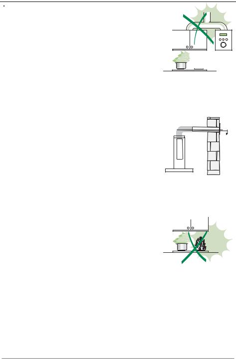
INSTALLATION
• The manufacturer will not be held liable for any damages resulting from incorrect or improper installation.
• The minimum safety distance between the cooker top and the extractor hood is 650 mm (some models can be installed at a lower height, please refer to the paragraphs on working dimensions
and installation).
• Check that the mains voltage corresponds to that indicated on the rating plate fixed to the inside of the hood.
• For Class I appliances, check that the domestic power supply guarantees adequate earthing. Connect the extractor to the exhaust flue through a pipe of minimum diameter 120 mm. The route of the flue must be as short as possible.
•Do not connect the extractor hood to exhaust ducts carrying combustion fumes (boilers, fireplaces, etc.).
•If the extractor is used in conjunction with non-electrical appliances (e.g. gas burning appliances), a sufficient degree of aeration must be guaranteed in the room in order to prevent the backflow of exhaust gas. The kitchen must have an opening communicating directly with the open air in order to guarantee the entry of clean air. When the cooker hood is used in conjunction with appliances
supplied with energy other than electric, the negative pressure in the room must not exceed 0,04 |
|
mbar to prevent fumes being drawn back into the room by the cooker hood. |
2° |
• In the event of damage to the power cable, it must be replaced by the manufacturer or by the |
|
technical service department, in order to prevent any risks. |
|
• If the instructions for installation for the gas hob specify a greater distance specified above, this has |
|
to be taken into account. Regulations concerning the discharge of air have to be fulfilled. |
|
USE
•The extractor hood has been designed exclusively for domestic use to eliminate kitchen smells.
•Never use the hood for purposes other than for which it has been designed.
•Never leave high naked flames under the hood when it is in operation.
•Adjust the flame intensity to direct it onto the bottom of the pan only, making sure that it does not engulf the sides.
•Deep fat fryers must be continuously monitored during use: overheated oil can burst into flames.
•Do not flambè under the range hood; risk of fire
•This appliance is not intended for use by persons (including children) with reduced physical, sensory or mental capabilities, or lack of experience and knowledge, unless they have been given supervision or instruction concerning use of the appliance by a person responsible for their safety.
•Children should be supervised to ensure that they do not play with the appliance.
•“ CAUTION: Accessible parts may become hot when used with cooking appliances.”.
MAINTENANCE
• Switch off or unplug the appliance from the mains supply before carrying out any maintenance work.
• Clean and/or replace the Filters after the specified time period (Fire hazard).
• Clean the hood using a damp cloth and a neutral liquid detergent.
The symbol  on the product or on its packaging indicates that this product may not be treated as household waste. Instead it shall be handed over to the applicablecollectionpointfortherecyclingofelectricalandelectronicequipment.Byensuringthisproductisdisposedofcorrectly,youwillhelppreventpotentialnegative consequencesfortheenvironmentandhumanhealth,whichcouldotherwisebecausedbyinappropriatewastehandlingofthisproduct.Formoredetailedinformation aboutrecyclingofthisproduct,pleasecontactyourlocalcityoffice,yourhouseholdwastedisposalserviceortheshopwhereyoupurchasedtheproduct.
EN |
|
5 |
|
5 |
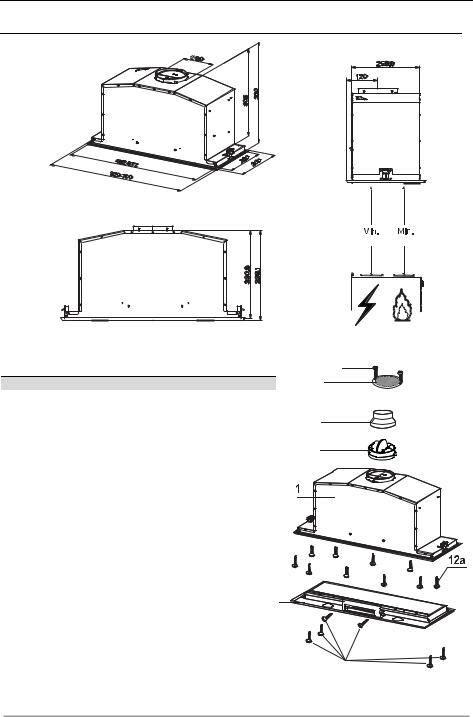
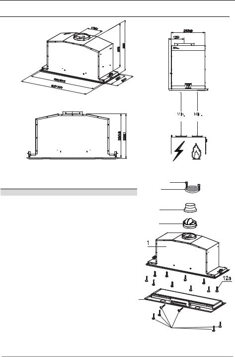
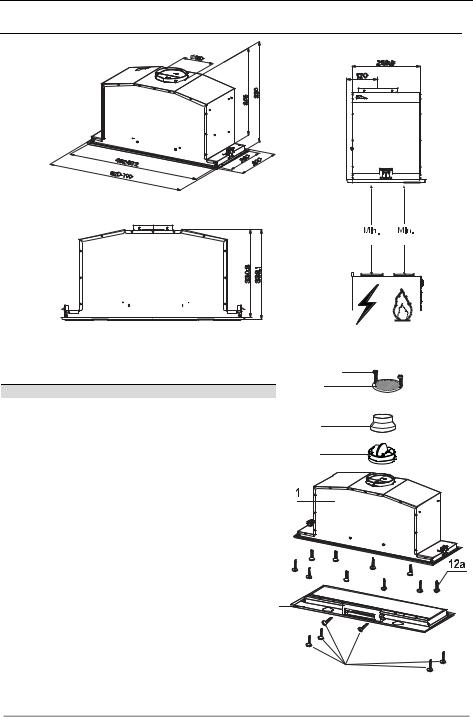
CHARACTERISTICS
Dimensions
530 mm 530 mm
Components
Ref. Q.ty Product Components
11 Hood Body, complete with :Controls, Light, Blower, Filters
2 |
1 |
Frame |
8 |
1 |
Directioned grid |
9 |
1 |
Reducer Flange ø 150-120 mm |
10 |
1 |
Damper ø 150 mm |
Ref. |
Q.ty |
Installation Components |
12a |
10 |
Screws |
12e |
2 |
Screws 2,9 x 9,5 |
12f |
6 |
Screws 2,9 x 6,5 |
|
Q.ty |
Documentation |
|
1 |
Instruction Manual |
12e
8
9
10
2 |
12f
EN |
|
6 |
|
6 |
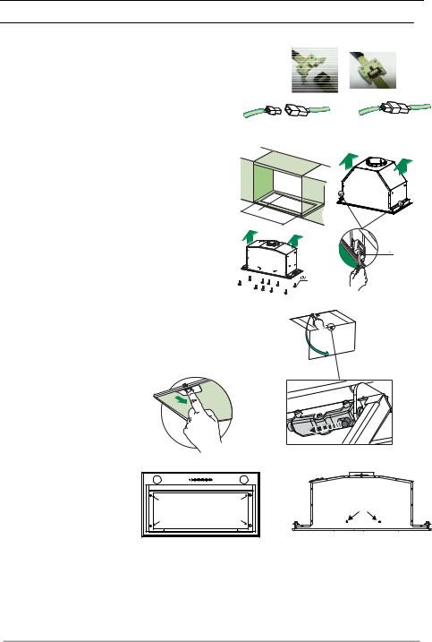
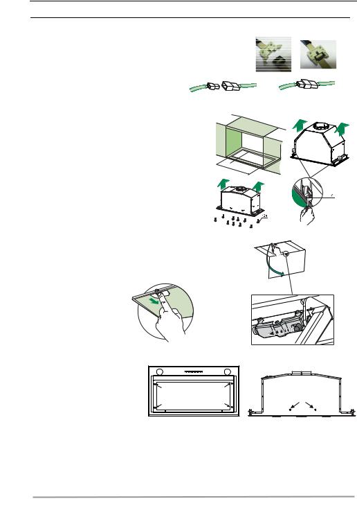
INSTALLATION
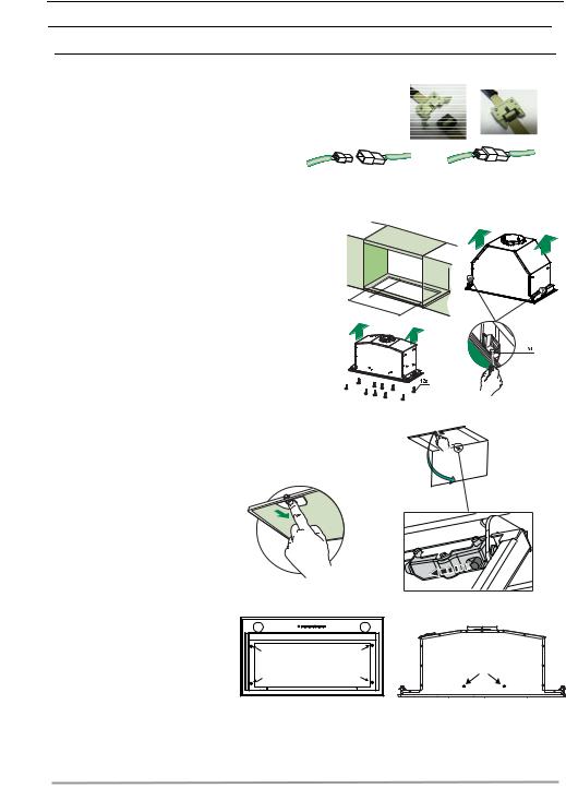
Fitting the Hood canopy
BEFORE FITTING THE HOOD TO THE WALL UNIT, PROCEED AS FOLLOWS:
•Disconnect the wires to the Commands at the connectors.
•Disconnect the wires to the Light at the con-
nectors.
•The Hood can be installed directly on the underside of the wall unit (Minimum 530 mm from the Cooker Hob).
•Create an opening in the bottom of the wall unit, as shown.
•Insert the hood until the side supports snap into place.
•Fasten using the 10 screws 12a provided.
•Lock in position by tightening the screws Vf from underneath the hood.
260
495 |
13 |
- |
|
|
675 |
•Open the suction panel by turning the specific knob.
•Disconnect the panel from the hood canopy by sliding fixing pin lever.
• Remove grease filters.
the |
•Screw the Frame into place using the 6 screws 12f, reconnect the wires to the Commands and Light, replace the metal grease filter and the Panel.
EN |
|
7 |
|
7 |
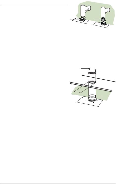
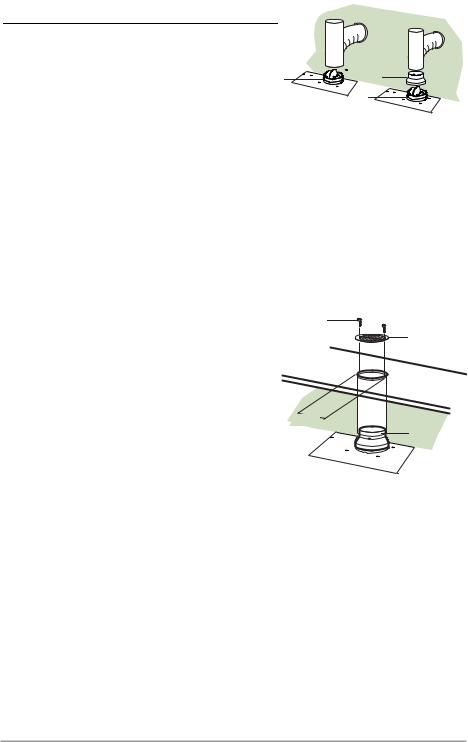
Connections
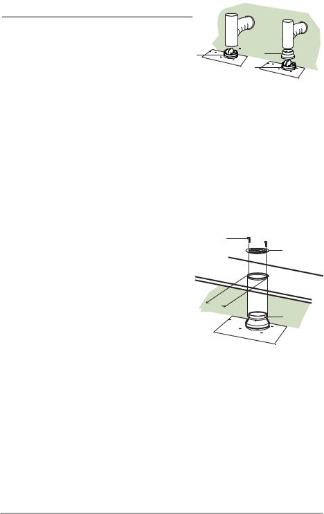
DUCTED VERSION AIR EXHAUST SYSTEM
When installing the ducted version, connect the hood to the chimney using either a flexible or rigid pipe ø 150 or 120mm, the choice of which is left to the installer.
To install a ø 150 pipe
•To install the dumper 10
•Fix the pipe in position using sufficient pipe clamps (not supplied).
To install a ø 120 pipe
•To install a ø 120 mm air exhaust connection, insert the reducer flange 9 on the dumper 10.
•Fix the pipe in position using sufficient pipe clamps (not supplied).
•Remove any activated charcoal filters.
RECIRCULATION VERSION AIR OUTLET
•Cut a hole ø 125 mm in any shelf that may be positioned over the hood.
•Insert the reducer flange 9 on the hood body outlet.
•Connect the flange to the outlet on the shelf over the hood by using a flexible or rigid pipe ø120 mm.
•Fix the pipe in position using sufficient pipe clamps (not supplied).
•Fix the air outlet grid 8 on the recirculation air outlet by using the 2 screws 12e (2,9 x 9,5) provided.
•Ensure that the activated charcoal filters have been inserted.
ø 150 |
ø 120 |
10 |
9 |
|
|
|
10 |
12e
8
ø 125 |
9 |
|
ELECTRICAL CONNECTION
•Connect the hood to the mains through a two-pole switch having a contact gap of at least 3 mm..
EN |
|
8 |
|
8 |
USE
|
|
|
|
|
|
|
|
L |
|
|
|
|
|
|
|
S1 |
T1 |
|
|
|
|
|
|
|
|
|
|
|
|
|
|
|
|
|
T2 |
L |
T1 |
|
T2 |
|
T3 |
T4 |
|
T3 |
|
|
|
|
|||||
|
S1 |
|
|
|
|
|
|
T4 |
|
|
|
|
|
|
|
|
S1 |
|
L |
T1 |
T2 |
T3 |
T4 |
|
|
|
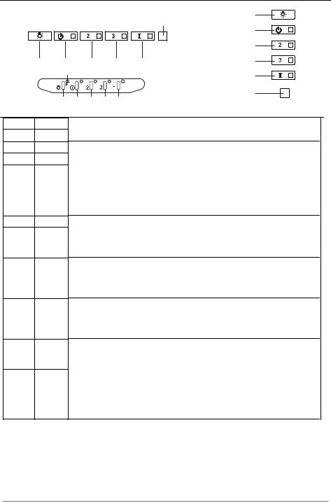
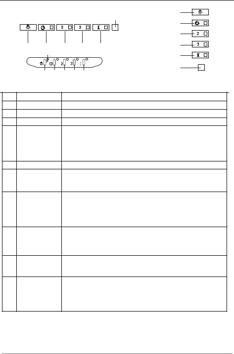
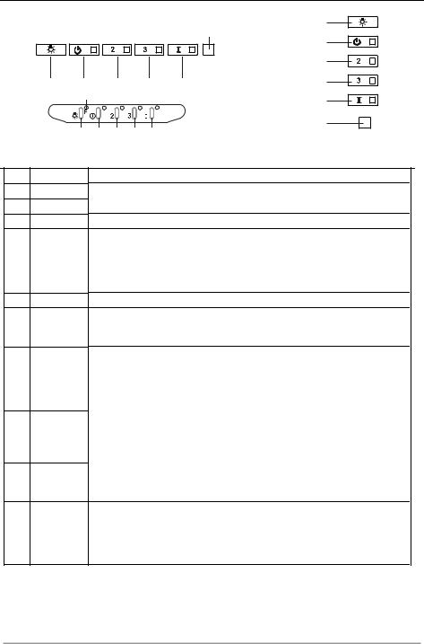
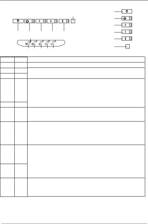
Control panel
Button Led
L -
T1 Fixed
T2 Fixed
T3 Fixed
T4 Fixed
S1 Fixed
Flashing
Function
Turns the lights on/off at maximum strength. Turns the motor on/off at speed one.
Turns the Motor on at speed two.
Press and hold the button for approximately 3 seconds, with all the loads turned off (Motor and Lights), to turn the Activated Charcoal Filter alarm on. The relevant LED flashes twice to confirm.
To turn the alarm off, press the button again and hold for at least 3 seconds. The relevant LED flashes once.
Turns the Motor on at speed three.
Press and hold the button for approximately 3 seconds, with all the loads turned off (Motor and Lights), to perform a reset of Filter saturation alarm. The LED S1 flashes three times.
Turns the Motor on at INTENSIVE Speed.
This speed is timed to run for 10 minutes. At the end of this time, the system returns automatically to the speed that was set before. If it is activated with the motor turned off, the hood will switch to OFF at the end of the time.
Press and hold for 3 seconds to enable the remote control, indicated by the LED flashing twice.
Press and hold for 3 seconds to disable the remote control, indicated by the LED flashing just once.
Signals the Metal Grease Filter saturation alarm, indicating that it is necessary to wash the filters. The alarm is triggered after the Hood has been in operation for 100 working hours. (Reset see the parag. Maintenance)
When this is activated, it signals the Activated Charcoal Filter saturation alarm, indicating that the filter must be changed; the Metal Grease Filters must also be washed. The Activated Charcoal Filter saturation alarm comes
into operation after the Hood has been working for 200 hours. (Activation and Reset see the parag. Maintenance)
EN |
|
9 |
|
9 |
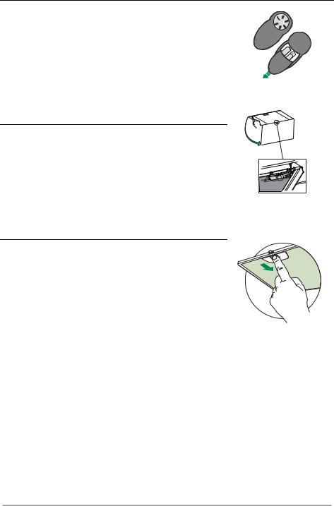
MAINTENANCE
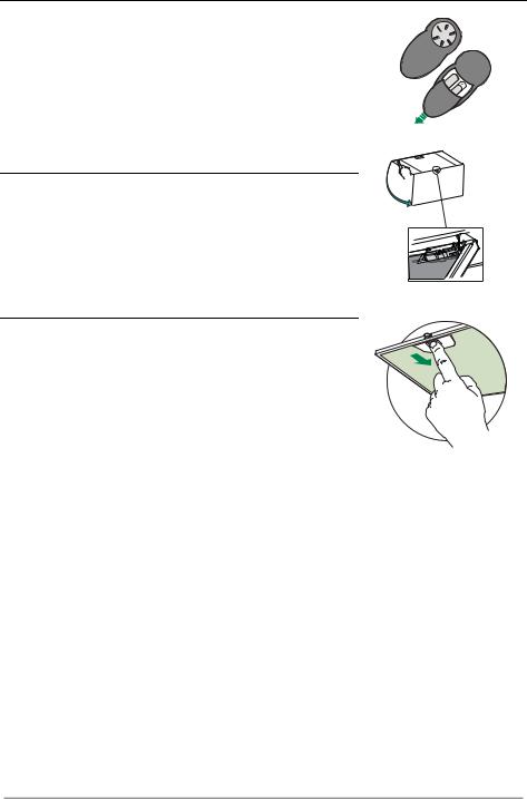
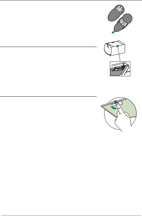
REMOTE CONTROL (OPTIONAL)
The appliance can be controlled using a remote control powered by a 1.5 V carbon-zinc alkaline batteries of the standard LR03AAA type (not included).
•Do not place the remote control near to heat sources.
•Used batteries must be disposed of in the proper manner.
Opening Panel
•Open the Panel by pulling it.
•Clean the outside with a damp cloth and neutral detergent.
•Clean the inside using a damp cloth and neutral detergent; do not use wet cloths or sponges, or jets of water; do not use abrasive substances.
Metal grease filters
These can be washed in the dishwasher, and need to be cleaned whenever the S1 Led comes on or at least once every 2 months use, or more frequently if use is particularly intensive.
CLEANING THE FILTERS
Resetting the alarm signal
•Turn the Lights and the Suction Motor off.
•Press T3 and hold for at least 3 seconds, until LED flashes three times in confirmation.
Cleaning the Filters
•Open the doors.
•Remove the Filter, pushing it towards the back of the unit and at the same time pulling downward.
•Wash the filter without bending it, and leave it to dry thoroughly before replacing (if the surface of the filter changes colour over time, this will have absolutely no effect on its efficiency).
•Replace, taking care to ensure that the handle faces forwards.
•Close the doors again.
EN |
|
1 |
|
10 |
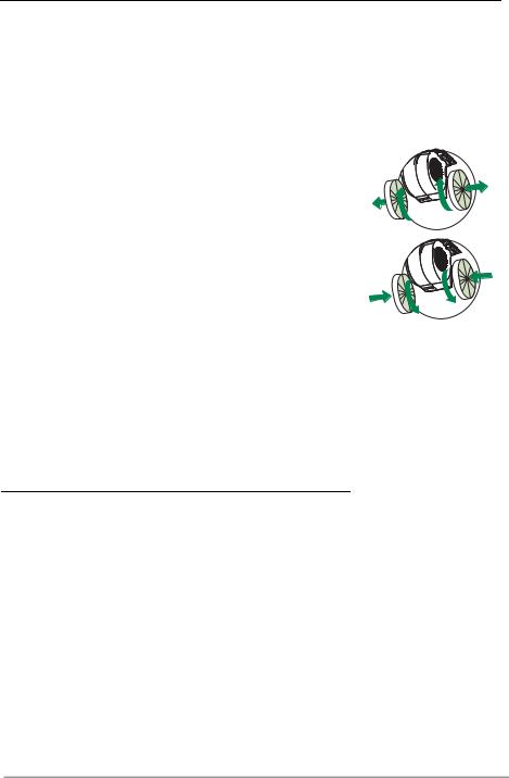
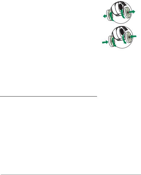
Activated Charcoal Filter (Recirculation Version)
This cannot be washed or regenerated, and must be changed when led S1 starts to flash, or at least once every 4 months. The Alarm signal, if it has been activated, only appears when the Suction motor is turned on.
Activating the alarm signal
•In Recirculation Version Hoods, the Filter Saturation Alarm must be activated on installation or at a later date.
•Turn the Lights and the Suction Motor off.
•Press button T2 and hold it for 5 seconds until the LED flashes twice in confirmation:
CHANGING
Resetting the alarm signal
•Turn the Lights and the Suction Motor off.
•Press T3 and hold for at least 3 seconds, until LED flashes three times in confirmation.
Changing the Filter
•Open the doors.
•Remove the Metal Grease Filter.
•Remove the saturated Activated Charcoal Filters, as indicated (A).
•Fit the new Filters, as indicated (B).
•Replace the Metal grease filters.
•Close the doors.
A
B |
Lighting unit
Warning: This appliance is fitted with a white LED lamp classed as 1M according to EN 60825-1: 1994 + A1:2002 + A2:2001 standards; maximum optical power emitted @439nm: 7µW. Do not look directly at the light through optical devices (binoculars, magnifying glasses…).
•For replacement contact technical support. ("To purchase contact technical support")
EN |
|
1 |
|
11 |
EMPFEHLUNGEN UND HINWEISE
 Diese Gebrauchsanleitung gilt für mehrere Geräte-Ausführungen. Es ist möglich, dass einzelne Ausstattungsmerkmalebeschriebensind,dienichtaufIhrGerätzutreffen.
MONTAGE
•Der Hersteller haftet nicht für Schäden, die auf eine fehlerhafte oder unsachgemäße Montage zurückzuführen sind.
• Der minimale Sicherheitsabstand zwischen Kochmulde und Haube muss 650 mm betragen (einige Modelle können an einer geringeren Höhe installiert werden, beziehen Sie sich dazu auf den Absatz Raumbedarf und Installation).
• Prüfen,obdieNetzspannungmitdemWertaufdemimHaubeninnerenangebrachtenSchildübereinstimmt.
• Bei Geräten der Klasse I ist sicherzustellen, dass die elektrische Anlage des Wohnhauses über eine vorschriftsmäßigeErdungverfügt.
• Das Anschlussrohr der Haube zur Luftaustrittsöffnung muss einen Durchmesser von 120 mm oder darüber aufweisen.DerRohrverlaufmusssokurzwiemöglichsein.
•Die Haube darf an keine Entlüftungsschächte angeschlossen werden, in die Verbrennungsgase (Heizkessel, Kamineusw.)geleitetwerden.
•Werden im Raum außer der Dunstabzugshaube andere, nicht elektrisch betriebene (z.B. gasbetriebene) Geräteverwendet, mussfüreine ausreichende Belüftunggesorgt werden.SolltedieKüche diesbezüglich nicht entsprechen, ist an einer Aussenwand eine Öffnung anzubringen, die Frischluftzufuhr gewährleistet. Der Gebrauch ist dann sachgemäß und sicher, wenn der max. Unterdruck des Raums nicht mehr als 0,04 mbar
beträgt.
• |
Ein schadhaftes Kabel muss vom Hersteller oder vom technischen Kundendienst ausgewechselt werden, |
2° |
|
damitjedesRisikovermiedenwird. |
|
|
|
|
• |
Wenn die Anweisungen für die Installation für die Gaskochgeräts einen größeren Abstand oben angegeben, |
|
|
mussdiesberücksichtigtwerden.VorschriftenüberdieEntlastungderLuftmüssenerfülltsein. |
|
BEDIENUNG
•Die Dunstabzugshaube ist ausschließlich zum Einsatz im privaten Haushalt und zur Beseitigung von Küchengerüchenvorgesehen.
•UnsachgemäßerEinsatzderHaubeistzuunterlassen.
• GroßeFlammenbeieingeschalteterHaubeniemalsunbedecktlassen.
•DieIntensivitätderFlammeistsozuregulieren,dasssiedenTopfbodennichtüberragt.
•FrittiergerätemüssenwährenddesGebrauchsstetsbeaufsichtigtwerden:überhitztesÖlkannsichentzünden.
•KeineflambiertenSpeisenunterderAbzugshaubezubereiten:Brandgefahr.
•Dieses Gerät darf nicht von Personen, auch Kindern, mit verminderten psychischen, sensorischen und geistigern Fähigkeiten, oder von Personen ohne Erfahrung und Kenntnisse benutzt werden, sofern sie nicht von für ihreSicherheitverantwortlichenPersonenbeaufsichtigtundbeimGebrauchdesGerätsangeleitetwerden.
•Kinder dürfen sich nicht unbeaufsichtigt in der Nähe des Geräts aufhalten und auf keinen Fall mit dem Gerät spielen.
•“ACHTUNG: Die zugänglichen Teile können sehr heiß werden, wenn sie mit Kochgeräten eingesetzt wer-
den.”.
WARTUNG
• Bevor Wartungsarbeiten durchgeführt werden, muss die Stromzufuhr zur Haube unterbrochen werden, indem derSteckergezogenoderderHauptschalterabgeschaltetwird.
•Bei der Filterwartung müssen die vom Hersteller empfohlenen Zeiträume zum Austauschen der Filter genauestenseingehaltenwerden(Brandgefahr).
•ZurReinigungderHaubenflächenWirempfehleneinfeuchtesTuchundeinmildesFlüssigreinigungsmittel.
Das Symbol  auf dem Produkt oder seiner Verpackung weist darauf hin, dass dieses Produkt nicht als normaler Haushaltsabfall zu behandeln ist, sondern an einem Sammelpunkt für das Recycling von elektrischen und elektronischen Geräten abgegeben werden muss. Durch Ihren Beitrag zum korrekten Entsorgen dieses Produkts schützen Sie die Umwelt und die Gesundheit Ihrer Mitmenschen. Umwelt und Gesundheit werden durch falsches Entsorgen gefährdet. Weitere Informationen über das Recycling dieses Produkts erhalten Sie von Ihrem Rathaus, Ihrer Müllabfuhr oder dem Geschäft, in dem Sie das Produkt gekauft haben.
DE |
|
1 |
|
12 |
CHARAKTERISTIKEN
Platzbedarf
530 mm 530 mm
Komponenten
Bez. Menge Produktkomponenten
11 Haubenkörper komplett mit: Bedienelemente, Beleuchtung, Filter, Absaugeinheit
2 |
1 |
Rahmen |
8 |
1 |
Luftstromrichtungsgitter |
9 |
1 |
Reduzierflansch ø 150-120 mm |
10 |
1 |
Flansch mit Ventil ø 150 mm |
Bez. |
Menge Produktkomponenten |
|
12a |
10 |
Schrauben |
12e |
2 |
Schrauben 2,9 x 9,5 |
12f |
6 |
Schrauben 2,9 x 6,5 |
|
Menge Unterlagen |
|
|
1 |
Betriebsanleitung |
12e
8
9
10
2 |
12f
DE |
|
1 |
|
13 |
MONTAGE
Montage des Haubenkörpers
BEVOR DIE HAUBE AM HÄNGESCHRANK MONTIERT WIRD, WIE FOLGT VORGEHEN:
•Die Drähte der Bedienelemente abhängen, indem die Verbinder gelöst werden.
•Die Drähte der Beleuchtung abhängen, indem die
Verbinder gelöst werden.
•Die Haube kann direkt an der Unterseite des Hängeschranks angebracht werden min. (530 mm von der Kochfläche).
•An der Unterseite des Hängeschranks eine Aussparung anfertigen, wie abgebildet.
•Die Haube einsetzen und die seitlichen Halterungen einhaken.
•Mit den 10 mitgelieferten Schrauben 12a befestigen.
•Durch Festschrauben von unten der Schrauben Vf definitiv blockieren.
260
495 |
13 |
- |
|
|
675 |
•Das Absaugpaneel herausziehen.
•Das Paneel vom Haubenkörper lösen, in dem der spezielle Hebel des Befestigungszapfens verschoben wird.
• Die Fettfilter entfernen.
• Sichern Sie den Rahmen mit den 6 Schrauben 12f, die Drähte an den Kontrollen und Beleuchtung wieder reinstallieren Sie die Fettfilter und Panel.
DE |
|
1 |
|
14 |
Anschlüsse
ANSCHLUSS IN ABLUFTVERSION
Bei Abluftbetrieb kann die Haube vom Installateur wahlweise mittels Rohr oder Schlauch (ø150 oder 120mm) an die Außenrohrleitung angeschlossen werden.
Anschlussrohres ø 150
•Den Flansch mit Ruckstauklappe 10 anbringen.
•Das Rohr mit geeigneten Rohrschellen fixieren.Das hierzu erforderliche Material wird nicht mitgeliefert.
ø 150 |
ø 120 |
10 |
9 |
|
|
|
10 |
Anschlussrohres ø 120
•Bei Verwendung eines Anschlussrohres ø 120 den Reduzierflansch 9 am Flansch mit Ruckstauklappe 10 anbringen.
•Das Rohr mit geeigneten Rohrschellen fixieren.Das hierzu erforderliche Material wird nicht mitgeliefert.
•Eventuell vorhandene Aktivkohlefilter entnehmen.
ANSCHLUSS IN UMLUFTVERSION
•In das eventuell über der Haube vorhandene Bord ein Loch ø 125 mm bohren.
•Den Reduzierflansch 9 am Haubenaustritt anbringen.
•Den Flansch beim Luftaustritt am Bord oberhalb der Haube mittels Rohr oder Schlauch ø120 mm anschließen.
•Das Rohr mit geeigneten Rohrschellen fixieren. Das hierzu erforderliche Material wird nicht mitgeliefert.
•Das Luftleitgitter 8 mit Hilfe von 2 der mitgelieferten Schrauben 12e (2,9 x 9,5) beim Austritt der rückzuführenden Luft fixieren.
•Sicherstellen, dass der Aktivkohle-Geruchsfilter vorhanden ist.
ELEKTROANSCHLUSS
12e
8
ø 125 |
9 |
|
•Bei Anschluss der Haube an das Stromnetz muss ein zweipoliger Schalter mit einem Öffnungsweg von mindestens 3 mm zwischengeschaltet werden.
DE |
|
1 |
|
15 |
BEDIENUNG
|
|
|
|
|
|
|
|
L |
|
|
|
|
|
|
|
S1 |
T1 |
|
|
|
|
|
|
|
|
|
|
|
|
|
|
|
|
|
T2 |
L |
T1 |
|
T2 |
|
T3 |
T4 |
|
T3 |
|
|
|
|
|||||
|
S1 |
|
|
|
|
|
|
T4 |
|
|
|
|
|
|
|
|
|
|
|
|
|
|
|
|
|
S1 |
|
L |
T1 |
T2 |
T3 |
T4 |
|
|
|
|
|
Schalttafel |
Taste |
LED |
Funktion |
L |
- |
Schaltet die Beleuchtung bei maximaler Intensität ein/aus. |
T1 |
Bleibend |
Schaltet den Motor bei der ersten Betriebsgeschwindigkeit ein/aus. |
T2 |
Bleibend |
Schaltet den Motor bei der zweiten Betriebsgeschwindigkeit ein. |
|
|
Mit zirka 5 Sekunden langem Gedrückthalten der Taste bei abgeschalteten |
|
|
Verbrauchern (Motor+Licht) wird der Alarm für aktive Aktivkohlefilter |
|
|
aktiviert und die entsprechende LED blinkt zweimal. |
|
|
Zum Abstellen die Taste erneut 5 Sekunden lang drücken, die |
|
|
entsprechende LED blinkt ein Mal. |
T3 |
Bleibend |
Schaltet den Motor bei der dritten Betriebsgeschwindigkeit ein. |
|
|
Mit zirka 3 Sekunden langem Gedrückthalten der Taste bei abgeschalteten |
|
|
Verbrauchern (Motor+Licht) erfolgt ein Reset und die LED S1 blinkt drei |
|
|
Mal. |
T4 |
Bleibend |
Schaltet den Motor bei Intensivgeschwindigkeit ein. |
|
|
Diese Geschwindigkeit ist auf 10 Minuten zeitgeregelt. Nach Ablauf dieser |
|
|
Zeit kehrt das System zu der zuvor eingestellten Geschwindigkeit zurück. |
|
|
Wird sie bei abgestelltem Motor aktiviert, wird nach Ablauf der Zeit zum |
|
|
Betriebsmodus OFF übergegangen. |
|
|
Mit 5 Sekunden langem Drücken wird die Fernbedienung aktiviert und die |
|
|
entsprechende LED blinkt zwei Mal. |
|
|
Mit 5 Sekunden langem Drücken wird die Fernbedienung deaktiviert und |
|
|
die entsprechende LED blinkt nur ein Mal. |
S1 |
Bleibend |
Meldet den Alarm für Sättigung der Metallfettfilter und die Notwendigkeit, |
|
|
diese zu waschen. Dieser Alarm wird nach 100 effektiven Betriebsstunden |
|
|
der Abzugshaube ausgelöst. (Reset siehe Absatz Wartung). |
|
Blinkend |
Meldet, sofern aktiviert, den Alarm für Sättigung des Aktivkohlefilters, der |
|
|
ausgewechselt werden muss; auch die Metallfettfilter müssen gewaschen |
|
|
werden. Der Alarm für Sättigung des Aktivkohlefilters wird nach 200 |
|
|
effektiven Betriebsstunden der Abzugshaube ausgelöst. (Aktivierung und |
|
|
Reset siehe Absatz Wartung). |
DE |
|
1 |
|
16 |
WARTUNG
FERNBEDIENUNG (OPTION)
Dieses Gerät kann mit einer Fernbedienung gesteuert werden, welche mit alkalischen Zink-Kohle-Batterien 1,5 V des Standardtyps LR03-AAA versorgt wird (nicht mitgeliefert).
•Die Fernbedienung nicht in die Nähe von Hitzequellen legen.
•Batterien müssen vorschriftsmäßig entsorgt werden.
Öffnen des Paneels
•Das Paneel herausziehen.
•Die Außenflächen mit einem feuchten Lappen und einem neutralen Flüssigreiniger säubern.
•Auch Innen mit einem feuchten Lappen und einem neutralen Reinigungsmittel säubern; keine nassen Tücher oder Schwämme, oder gar Wasser verwenden, und keine schleifenden Mittel einsetzen.
Metallfettfilter
Die Fettfilter sind spülmaschinengeeignet und müssen gewaschen werden, sobald sich die LED S1 einschaltet, oder mindestens alle 2 Monate, oder auch öfter, je nach Intensität des Gebrauchs.
REINIGUNG DER FILTER
Reset des Alarmsignals
•Die Beleuchtung und den Absaugmotor abstellen.
•Die Taste T3 mindestens 3 Sekunden lang drücken, bis der Vorgang durch dreimaliges Blinken der LED bestätigt wird.
Reinigung der Filter
•Die Klappen öffnen.
•Den Filter zu dem hinteren Teil der Gruppe schieben und gleichzeitig nach unten ziehen.
•Den Filter waschen, ohne ihn zu verbiegen, und vor dem Wiedereinbau trocknen lassen (die Farbe der Filteroberfläche kann sich mit der Zeit verändern, was aber die Wirksamkeit keinesfalls beeinträchtigt.)
•Nun den Filter wieder einbauen, so dass der Griff nach der äußeren Sichtseite zeigt.
•Die Klappen wieder verschließen.
DE |
|
1 |
|
17 |
Aktivkohle-Geruchsfilter (Filterversion)
Der Aktivkohlefilter ist weder waschbar, noch regenerierbar und muss ausgewechselt werden, wenn die LED S1 blinkt, oder mindestens alle 4 Monate. Die Alarmmeldung, wenn zuvor aktiviert, erfolgt nur, wenn der Absaugmotor zugeschaltet ist.
Aktivierung des Alarmsignals
•Bei den Filterversionen der Abzugshauben wird die Alarmanzeige für Filtersättigung im Augenblick der Installation oder in der Folge aktiviert.
•Die Beleuchtung und den Absaugmotor abstellen.
•5 Sekunden lang die Taste T2 drücken, bis die LED zur Bestätigung blinkt:
AUSWECHSELN
Reset des Alarmsignals
•Die Beleuchtung und den Absaugmotor abstellen.
•Die Taste T3 mindestens 3 Sekunden lang drücken, bis der Vorgang durch dreimaliges Blinken der LED bestätigt wird.
Auswechseln des Filters
•Die Klappen öffnen.
•Den Fettfilter ausbauen.
•Die verbrauchten Aktivkohle-Geruchsfilter wie angegeben ausbauen (A).
•Die neuen Filter wie angegeben einbauen (B).
•Den Fettfilter wieder einbauen.
•Die Klappen wieder verschließen.
A
B |
Beleuchtung
LED-Strahler
•Für den Austausch der LED-Strahler wenden Sie sich bitte an den Kundendienst.
Achtung: Dieses Gerät ist mit einer weißen LED-Lampe der Klasse 1M gemäß EN 60825-1 ausgestattet: 1994 + A1:2002 + A2:2001; max. gelieferte Lichtleistung @439nm: 7µW. Nicht direkt mit optischen Instrumenten (Fernglas, Lupe, usw.) in das Licht schauen.
DE |
|
1 |
|
18 |

CONSEJOS Y SUGERENCIAS
 Las presentes instrucciones de servicio son válidas para diferentes modelos de aparato; por ello puede ser posible que se describan detalles y características de equipamiento que no concuerden íntegramenteconlasdesuaparatoconcreto.
INSTALACIÓN
• El fabricante declina cualquier responsabilidad debida a los daños provocados por una instalación incorrectaonoconformeconlasreglas.
• La distancia mínima de seguridad entre la encimera y la campana debe ser de 650mm (algunos modelospuedenserinstaladosaunaalturapordebajo, serefierenalpárrafohuellaylainstalación).
• Comprobar que la tensión de red corresponda a la indicada en la placa situada en el interior de la campana.
• Para los aparatos Clase I asegurarse de que la instalación eléctrica doméstica posea una toma de tierraeficaz.
•Conectar la campana a la salida del aire de aspiración mediante un tubo de 120mm de diámetro comomínimo. El recorridodeltubodebeserlomáscortoposible.
•No conectar la campana a tubos de descarga de humos producidos por combustión (calderas, chimeneas, etc.).
•En el caso que en la cocina se utilice de manera silmultánea la campana y otros aparatos no eléctricos (por ejemplo aparatos de gas), debe existir un sistema de ventilación suficiente para todo el ambiente. Si la cocina no posee un orificio que comunique con el exterior, hay que realizarlo para garanti-
zar el recambio del aire. Un uso propio y sin riesgos se obtiene cuando la depresión máxima del local |
|
|
nosuperalos0,04 mBar. |
2° |
|
• En el caso se dañe el cable de alimentación, éste debe ser sustituido por el constructor o por el servi- |
||
|
||
ciodeasistenciatécnica, paraprevenircualquierriesgo. |
|
•Si las instrucciones de instalación del dispositivo de cocción de gas sugieren la necesidad de una distancia mayor que la indicada anteriormente, es necesario tenerlas en cuenta. Es necesario respetartodaslasnormativasrelativasal conductodedescargadelaire.
USO
• La campana ha sido concebida exclusivamente para un uso doméstico, para eliminar los olores de la cocina. Noutilizarlademanerainadecuada.
•Nodejarllamaslibresdefuerteintensidad mientraslacampanaestéfuncionando.
•Regular siempre las llamas de manera que éstas no sobresalgan lateralmente con respecto al fondo delasollas.
•Controlarlasfreídorasdurantesuuso: elaceitemuycalientesepuedeinflamar.
•Noflambearbajola campanaextractora.
•Este aparato no tiene que ser utilizado por personas (niños incluídos) con capacidades psíquicas, sensoriales o mentales reducidas, o bien por personas sin experiencia y conocimientos en la materia, a menosquenolohaganbajoel control, oinstruídos, porpersonasresponsables de suseguridad.
•Controlarquelosniñosnojueguenconel aparato.
• “ATENCIÓN: Laspartesaccesiblespuedencalentarse muchosiutilizadasconaparatosdecocción.”
MANTENIMIENTO
• Antes de efectuar cualquier operación de mantenimiento, desenchufar la campana de la red eléctrica o apagarelinterruptorgeneral.
•Efectuar un mantenimiento escrupuloso e inmediato de los filtros, según los intervalos de tiempo aconsejados(riesgodeincendio).
•Para limpiar las superficies de la campana es suficiente utilizar un trapo mojado y detergente líquido neutro.
El símbolo  en el producto o en su embalaje indica que este producto no se puede tratar como desperdicios normales del hogar. Este producto se debe entregar al punto de recolección de equipos eléctricos y electrónicos para reciclaje. Al asegurarse de que este producto se deseche correctamente, usted ayudará a evitar posibles consecuencias negativas para el ambiente y la salud pública, lo cual podría ocurrir si este producto no se manipula de forma adecuada. Para obtener información más detallada sobre el reciclaje de este producto, póngase en contacto con la administración de su ciudad, con su servicio de desechos del hogar o con la tienda donde compró el producto.
ES |
|
1 |
|
19 |
CARACTERÍSTICAS
Dimensiones
530 mm 530 mm
Componentes
Ref. Cant Componentes del producto
11 Cuerpo campana dotado de: Mandos, luz, filtros, grupo aspirador.
2 |
1 |
Marco |
8 |
1 |
Rejilla direccionada |
9 |
1 |
Brida de reducción ø 150-120 mm |
10 |
1 |
Brida con válvula ø 150 mm |
Ref. |
Cant |
Componentes de instalación |
12a |
10 |
Tornillos |
12e |
2 |
Tornillos 2,9 x 9,5 |
12f |
6 |
Tornillos 2,9 x 6,5 |
|
Cant |
Documentación |
|
1 |
Manual de instrucciones |
12e
8
9
10
2 |
12f
ES |
|
2 |
|
20 |
INSTALACIÓN
Montaje del cuerpo de la campana
ANTES DE MONTAR LA CAMPANA EN EL ARMARIO DE PARED, PROCEDA DE LA SIGUIENTE
MANERA:
• Desconectar los cables de los mandos mediante los conectores.
•Desconectar los cables de las luces mediante los conectores.
•La hotte peut être installée directement sur le plan inférieur des armoires murales (530 mm min. par rapport au plan de cuisson).
•Faire une entaille sur le plan inférieur de l’armoire murale, de la manière indiquée.
•Insérer la Hotte jusqu’à accrocher les Supports latéraux par encliquetage.
•Fixer avec 10 vis 12a fournies.
•Bloquer définitivement en serrant les Vis Vf depuis le bas de la Hotte.
260
495 |
13 |
- |
|
|
675 |
• Ouvrir le panneau en le tirant.
• Décrocher le panneau du corps de la hotte, en faisant coulisser le levier du goujon de fixation spécialement prévu.
• Retirer les filtres à graisse.
• Visser le cadre avec les 6 vis 12f, rebrancher le câblage des commandes et lumières, remonter le filtre à graisse et fermer le panneau.
ES |
|
2 |
|
21 |

Conexiones
SALIDA DEL AIRE VERSION ASPIRANTE
Para instalar la campana en versión aspirante conectarla a la tubería de salida mediante un tubo rígido ó flexible de 150 ó 120 mm, cuya elección se deja al instalador.
Conexión mediante tubo de Ø 150
•Insertar la arandela Ø 150 10 en la salida del cuerpo de la campana.
•Sujetar el tubo con unas fajillas. El material necesario no está incluído en la dotación.
Conexión mediante tubo de Ø 120
•Para conectarla mediante un tubo de Ø 120 mm, insertar la arandela de reducción 9 en la arandela Ø 150 10 que hemos colocado antes.
•Sujetar el tubo con unas fajillas. El material necesario no está incluído en la dotación.
•En los dos casos, quitar el filtro antiolor al cabón activado si estubiera colocado.
ø 150 |
ø 120 |
10 |
9 |
|
|
|
10 |
SALIDA DEL AIRE VERSIÓN FILTRANTE
•Realizar un orificio de ø 125 mm en la repisa de encima de la campana.
•Introducir la brida de reducción 9 en la salida del cuerpo de la campana.
•Conectar la salida del cuerpo de la campana con la parte superior del mueble colgante mediante un tubo rígido o flexible de ø120 mm, a discreción del instalador.
•Fijar el tubo con abrazaderas adecuadas. Este material no se proporciona en dotación.
•Fijar la rejilla de dirección 8 en la salida del aire reciclado mediante los 2 tornillos 12e (2,9 x 9,5) en dotación.
•Controlar que estén presentes los Filtros Antiolor al Carbón activo.
CONEXIÓN ELÉCTRICA
12e
8
ø 125 |
9 |
|
•Conectar la campana a la red de alimentación eléctrica instalando un interruptor bipolar con apertura de los contactos de 3 mm como mínimo.
ES |
|
2 |
|
22 |
USO
|
|
|
|
|
|
|
|
L |
|
|
|
|
|
|
|
S1 |
T1 |
|
|
|
|
|
|
|
|
|
|
|
|
|
|
|
|
|
T2 |
L |
T1 |
|
T2 |
|
T3 |
T4 |
|
T3 |
|
|
|
|
|||||
|
S1 |
|
|
|
|
|
|
T4 |
|
|
|
|
|
|
|
|
|
|
|
|
|
|
|
|
|
S1 |
|
L |
T1 |
T2 |
T3 |
T4 |
|
|
|
Tablero de mandos
Tecla Led
L -
T1 Fijo
T2 Fijo
T3 Fijo
T4 Fijo
S1 Fijo
Intermitente
Función
Enciende/Apaga las luces a la máxima velocidad. Enciende/Apaga el motor a la primera velocidad Enciende el motor a la segunda velocidad.
Manteniendo presionada la tecla por aproximadamente 5 segundos, cuando todas las cargas están apagadas (Motor+Luz) se activa la alarma de los filtros al carbono activo visualizando un doble parpadeo del led correspondiente.
Para desactivarlo, se presiona de nuevo la tecla por otros 5 segundos visualizando un parpadeo simple del led correspondiente.
Enciende el motor a la tercera velocidad.
Manteniendo presionada la tecla por aproximadamente 3 segundos, cuando todas las cargas están apagadas (Motor+Luz) se efectúa el reset visualizando el triple parpadeo del led S1.
Enciende el motor a la velocidad INTENSIVA.
Esta velocidad está temporizada en 10 minutos. Una vez terminado el tiempo, el sistema vuelve automáticamente a la velocidad seleccionada precedentemente. Si se activa desde motor apagado una vez terminado el tiempo pasa a la modalidad OFF.
Manteniendo presionada por 5 segundos se habilita el telemando visualizando un doble parpadeo del mismo led.
Manteniendo presionada la tecla por 5 segundos se deshabilita el telemando visualizando el parpadeo del led correspondiente una sola vez.
Señala la alarma de saturación filtros antigrasa metálicos y la necesidad de lavarlos. La alarma entra en función después de 100 horas de trabajo efectivo de la campana (Reset ver párr. Mantenimiento)
Señala, cuando está activada, la alarma de saturación filtro antiolor al carbono activo que debe ser sustituido;deben lavarse además los filtros antigrasa metálicos. La alarma de saturación filtro antiolor al carbono activo entra en función después de 200 horas de trabajo efectivo de la campana (Activación y reset ver párr. Mantenimiento)
ES |
|
2 |
|
23 |
MANTENIMIENTO
MANDO A DISTANCIA (OPCIONAL)
El aparato puede comandarse con un mando a distancia que funciona con pilas alcalinas zinkcarbón de 1,5 V del tipo standard LR03-AAA (no incluido).
•No dejar el mando a distancia cerca de una fuente de calor.
•Tirar las pilas, cuando se hayan agotado, en los contenedores especiales colocados con dicho fin.
Apertura panel
•Abrir el panel tirándolo.
•Limpiarlo externamente con un paño húmedo y detergente líquido neutro.
•Limpiarlo también internamente utilizando un paño húmedo y detergente neutro; no utilizar paños o esponjas mojadas, ni chorros de agua, no utilizar sustancias abrasivas.
Filtros antigrasa metálicos
Se pueden lavar en lavavajilla, y necesitan ser lavados cuando el led S1 se enciende o almenos cada 2 meses de uso aproximadamente o más frecuentemente, para un uso particularmente intenso.
LIMPIEZA DE LOS FILTROS
Reset de la señal de alarma
•Apagar las luces y el motor de aspiración.
•Presionar la tecla T3 por almenos 3 segundos, hasta el triple parpadeo de confirmación del led.
Limpieza de los filtros
•Abrir las puertas.
•Quitar el filtro empujándolo hacia la parte posterior del grupo y tirando simultáneamente hacia abajo.
•Lavar el filtro evitando doblarlo y dejarlo secar antes de volverlo a montar (un eventual cambio de color de la superficie del filtro, que podría verificarse en el transcurso del tiempo, no perjudica absolutamente la eficiencia del mismo).
•Montar nuevamente el filtro teniendo cuidado de mantener la manija hacia la parte visible externa.
•Volver a cerrar las puertas.
ES |
|
2 |
|
24 |
Filtros antiolor al carbono activo (versión filtrante)
No es lavable y no es regenerable, debe ser sustituido cuando el led S1parpadea o por lo menos cada 4 meses. La señalización de alarma si ha sido previamente activada, se verifica sólo cuando está activado el motor de aspiración.
Activación de la señal de alarma
•En las campanas de versión filtrante, la señalización de alarma saturación filtros debe activarse en el momento de la instalación o sucesivamente.
•Apagar las luces y el motor de aspiración.
•Presionar por 5 segundos la tecla T2 hasta el doble parpadeo de confirmación del led:
SUSTITUCIÓN
Reset de la señal de alarma
•Apagar las luces y el motor de aspiración.
•Presionar la tecla T3 por almenos 3 segundos hasta el triple parpadeo de confirmación del led
Sustitución filtro
•Abrir las puertas.
•Quitar el filtro antigrasa.
•Quitar los filtros antiolor al carbono activo saturados, como se indica en (A).
•Montar los nuevos filtros, como se indica en (B).
•Quitar el filtro antigrasa.
•Cerrar las puertas.
A
B |
Iluminación
Atención : Este aparato está provisto de una luz LED blanca de clase 1 M según la norma EN 60825-1: 1994 + A1:2002 + A2:2001; máxima potencia óptica emitida@439nm: 7µW. No observar directamente con instrumentos ópticos (catalejo, lupa……..)
. Para la sustitución ponerse en contacto con la Asistencia Técnica. ("Para la compra dirigirse a la asistencia técnica").
ES |
|
2 |
|
25 |

UWAGI I SUGESTIE
 Niniejsza instrukcja obsługi została przygotowana dla różnych wersji urządzenia. Możliwe jest, że niektóre ilustracje nie odzwierciedlajądokładnie waszego urządzenia.
MONTAŻ
•Producent nie ponosi żadnej odpowiedzialności za szkody powstałe w wyniku niewłaściwego i niezgodnego z zasadami techniki montażu.
• Minimalna odległośćbezpieczeństwa pomiędzy płytąkuchennąa okapem musi wynosić650 mm (niektóre modele mogą być instalowane na niższej wysokości, patrz paragrafy dotyczące ustawienia oraz instalacji).
• Sprawdź, czy napięcie w sieci elektrycznej odpowiada danym umieszczonym na tabliczce znamionowej wewnątrz okapu.
• W przypadku urządzeńklasy Ia należy sięupewnić, czy domowa instalacja elektryczna gwarantuje prawidłowe uziemienie.
•Podłącz okap do wlotu otworu wyciągowego za pomocąrury o średnicy równej lub większej niż 120 mm. Trasa rury powinna byćmożliwie najkrótsza.
•Nie podłączaj okapu do przewodów odprowadzających spaliny (z kotłów, kominków, itp.).
•Jeżeli w pomieszczeniu używane są zarówno okap, jak i urządzenia niezasilane energią elektryczną(na przykład urządzenia na gaz), należy zapewnićodpowiedniąwentylacjępomieszcze-
nia. Jeżeli w kuchni nie ma wywietrzników zapewniających dopływ świeżego powietrza, należy je wykonać. Bezpieczne użytkowanie okapu jest wówczas, gdy maksymalne podciśnienie w pomieszczeniu nie przekracza 0,04 mbar.
• Jeżeli kabel zasilający zostanie uszkodzony, powinien zostać wymieniony przez producenta lub |
2° |
|
wykwalifikowanych pracowników serwisu. |
||
|
||
• Jeśli instrukcja instalacji urządzenia do gotowania wskazuje na potrzebę zastosowane większej |
|
|
odległości, niż podana powyżej, należy to wziąć pod uwagę. Należy przestrzegać wszystkich |
|
|
norm dotyczących od-prowadzania powietrza. |
|
UŻYTKOWANIE
•Okap zostałzaprojektowany wyłącznie do użytku domowego, do neutralizacji zapachów kuchennych.
•Nie wolno używaćokapu do innych celów.
•Nie pozostawiaj wolnego ognia o dużej intensywności pod załączonym okapem.
•Reguluj zawsze płomienie tak, aby nie wydostawały sięone po bokach garnków.
•Nie zostawiaj patelni bez nadzoru podczas ich użytkowania : przegrzany olej może sięzapalić.
•Niniejsze urządzenie nie może byćużywane przez osoby (w tym dzieci) niepełnosprawnie fizycznie lub umysłowo oraz przez bez doświadczenia lub wiedzy na temat jego działania, operatorzy powinni zostać poinstruowani i skontrolowani we kwestii obsługi urządzenia przez osoby odpowiedzialne za jego bezpieczeństwo.
•Dzieci powinny byćnadzorowane, aby upewnićsięże nie bawiąsięurządzeniem.
•„UWAGA: Części zewnętrzne mogąstaćsiębardzo gorące, jeżeli używane sąrazem z urządze-
niami przeznaczonymi do gotowania.”
KONSERWACJA
• Przed przystąpieniem do dowolnej czynności konserwacyjnej należy wyłączyćokap z sieci elektrycznej, wyciagając wtyczkęlub wyłączając wyłącznik gówny.
•Wykonuj skrupulatnąi częstąkonserwacjęfiltra zgodnie z podanym opisem(Niebezpieczeństwo pożaru).
•Powierzchnie okapu wystarczy czyścićwilgotnąszmatkąi neutralnym płynem do mycia.
Symbol na produkcie lub na opakowaniu oznacza, że produktu tego nie można traktować jak zwykłych odpadów, ale należy go zawieźć do punktu zajmującego się likwidacją urządzeń elektrycznych i elektronicznych. Likwidując produkt w sposób właściwy, przyczyniasz się do zapobiegania ewentualnym ujemnym wpływom na środowisko i na zdrowie ludzi, które mogłyby powstać w wyniku niewłaściwej jego likwidacji. Szczegółowe informacje na temat recyclingu tego produktu uzyskasz w urzędzie miasta/gminy, lokalnych instytucjach zajmujących się likwidacja odpadów lub w sklepie, w którym kupileś produkt.
PL |
|
2 |
|
26 |

WŁAŚCIWOŚCI TECHNICZNE
Wymiary
530 mm 530 mm
Części składowe
Odn. Il. Części składowe urządzenia
11 Korpus okapu wraz z: przyciskami sterowania, oświetleniem, filtrami, wyciągiem.
2 |
1 |
Profil Ramy |
8 |
1 |
Kratka kierunkowa |
9 |
1 |
Kołnierz redukcyjny ø 150-120 mm |
10 |
1 |
Kołnierz z zaworem ø 150 mm |
Odn. |
Il. |
Elementy montażowe |
12a |
10 |
Śruby |
12e |
2 |
Śruby 2,9 x 9,5 |
12f |
6 |
Śruby 2,9 x 6,5 |
|
Il. |
Dokumentacja |
|
1 |
Instrukcja |
12e
8
9
10
2 |
12f
PL |
|
2 |
|
27 |
INSTALACJA
Montaż korpusu okapu
PRZED MONTAŻEM OKAPU NALEŻY:
•Odłączyć ze złącza okablowanie sterowania.
•Odłączyć ze złącza okablowanie
oświetlenia.
•Okap może być zamocowany na powierzchni dolnej innych mebli wiszących (min 530 mm od powierzchni kuchenki).
•Wykonać mocowanie na dolnej powierzchni wiszącego mebla, jak pokazano poniżej.
•Wsunąć okap aż do zamocowania na zaczepach.
•Przykręcić przy pomocy 10 śrub 12a znajdujących się w zestawie.
• Przy pomocy śrub Vf dokładnie zablokować okap od spodu.
260
495 |
13 |
- |
|
|
675 |
•Otworzyć panel wyciągowy, pociągając go.
•Odczepić panel od korpusu okapu przesuwając dźwignię sworznia mocującego.
• Wyjąć filtry przeciwtłuszczowe.
• Przykręcić ramkę z 6 śrub 12f, podłączyć przewody sterowania i oświetlenia, filtr tłuszczowy i panel.
PL |
|
2 |
|
28 |
Podłączenia
WYLOT POWIETRZA – WERSJA Z WYCIĄGIEM
Przy instalacji w wersji z wyciągiem należy podłączyć okap do przewodu rurowego wylotowego za pomocą sztywnej lub giętkiej rury o średnicy 150 lub 120 mm, według decyzji montera.
Podłączenie rury o ø 150 mm
•Nałóż kołnierz o średnicy 150 10 na wylot korpusu okapu.
•Zamocuj rurę odpowiednimi opaskami zaciskowymi. Potrzebnych do tego elementów nie ma w wyposażeniu.
Podłączenie rury ø 120
•Aby podłączyć rurę o średnicy 120 mm, nałóż kołnierz redukcyjny 9 na wcześniej zamontowany kołnierz o ø 150
10.
•Zamocuj rurę odpowiednimi opaskami zaciskowymi. Potrzebnych do tego elementów nie ma w wyposażeniu.
•W obydwóch przypadkach wyjmij ewentualne filtry węglowe pochłaniające zapachy.
PRACA W TRYBIE RECYRKULACJI
•Jeżeli ponad okapem znajduje się półka należy wyciąć w niej otwór ø 125 mm.
•Założyćkołnierz redukujący 9 na wylot powietrza.
•Połączyć kołnierz redukujący z wylotem powietrza zamocowanym w półce za pomocą giętkiej lub sztywnej rury ø 120 mm.
•Zamocować rurę za pomocą odpowiednich klamer zaciskowych do rur (nie znajdująsięw zestawie).
•Zamocować kratkę wentylacyjną 8 na wylocie powietrza w półce przy użyciu 2 wkrętów 12e (2,9 x 9,5, w zestawie).
•Upewnićsięczy zamontowano filtry węglowe.
ø 150 |
ø 120 |
10 |
9 |
|
|
|
10 |
12e
8
ø 125 |
9 |
|
PODŁĄCZENIE DO SIECI ELEKTRYCZNEJ
•Podłączyć okap do sieci elektrycznej za pośrednictwem dwubiegunowego włącznika o minimalnej rozwartości styków wynoszącej 3 mm.
PL |
|
2 |
|
29 |
UŻYTKOWANIE
|
|
|
|
|
|
|
|
L |
|
|
|
|
|
|
|
S1 |
T1 |
|
|
|
|
|
|
|
|
|
|
|
|
|
|
|
|
|
T2 |
L |
T1 |
|
T2 |
|
T3 |
T4 |
|
T3 |
|
|
|
|
|||||
|
S1 |
|
|
|
|
|
|
T4 |
|
|
|
|
|
|
|
|
|
|
|
|
|
|
|
|
|
S1 |
|
L |
T1 |
T2 |
T3 |
T4 |
|
|
|
Panel sterowania
Przycisk Dioda
L -
T1 Stała
T2 Stała
T3 Stała
T4 Stała
S1 Stała
Miga
Funkcja
Włączenie/wyłączenie oświetlenia z maksymalną jasnością. Włączenie/wyłączenie silnika z pierwszą prędkością. Uruchomienie silnika z drugą prędkością.
Przez naciśnięcie przycisku na około 5 sekund, w momencie gdy urządzenie jest wyłączone (silnik + oświetlenie), aktywuje się alarm filtrów węglowych, co sygnalizowane jest przez podwójne mignięcie odpowiedniej diody LED.
Aby go wyłączyć, należy ponownie nacisnąć przycisk na 5 sekund, co zostanie zasygnalizowane przez jedno mignięcie odpowiedniej diody LED.
Uruchomienie silnika z trzecią prędkością.
Przez naciśnięcie przycisku na około 3 sekundy, w momencie gdy urządzenie jest wyłączone (silnik + oświetlenie), następuje reset urządzenia, co sygnalizowane jest przez trzy mignięcia diody S1.
Uruchomienie silnika z prędkością INTENSYWNĄ.
Czas trwania tej prędkości ograniczony jest do 10 minut. Po zakończeniu tego czasu, system powraca automatycznie do wcześniej ustawionej prędkości. Jeżeli funkcja aktywowana została przy wyłączonym silniku, wówczas urządzenie przechodzi do tryby wyłączonego – OFF.
Jeżeli przycisk przytrzymany zostanie na 5 sekund – włączone zostaje zdalne sterowanie, co sygnalizowane jest przez podwójne mignięcie diody LED.
Ponowne naciśnięcie przycisku na 5 sekund powoduje wyłączenie zdalnego sterowania, co sygnalizowane jest przez pojedyncze mignięcie diody LED.
Alarm sygnalizuje alarm nasycenia tłuszczowych filtrów metalowych i konieczność ich wyczyszczenia. Alarm załącza się po 100 godzinach rzeczywistej pracy okapu (patrz Reset par. Konserwacja).
Sygnalizuje, jeśli jest aktywny, alarm nasycenia węglowego filtru zapachowego, który należy wymienić; należy także umyć metalowe filtry tłuszczowe. Alarm nasycenia węglowego filtru antyzapachowego aktywuje się po 200 godzinach rzeczywistej pracy okapu (patrz Aktywacja i Reset par. Konserwacja).
PL |
|
3 |
|
30 |
 Loading...