


Instructions Manual
Руководство по эксплуатации
ﺐﻴآﺮﺘﻟا ﻞﻴﻟد

INDEX
EN
RECOMMENDATIONS AND SUGGESTIONS |
..................................................................................................................... 3 |
CHARACTERISTICS ............................................................................................................................................................. |
4 |
INSTALLATION...................................................................................................................................................................... |
6 |
USE ...................................................................................................................................................................................... |
10 |
MAINTENANCE ................................................................................................................................................................... |
11 |
УКАЗАТЕЛЬ |
RU |
СОВЕТЫ И РЕКОМЕНДАЦИИ.......................................................................................................................................... |
13 |
ХАРАКТЕРИСТИКИ............................................................................................................................................................ |
14 |
УСТАНОВКА........................................................................................................................................................................ |
16 |
ЭКСПЛУАТАЦИЯ................................................................................................................................................................ |
20 |
УХОД.................................................................................................................................................................................... |
21 |
|
SA |
سﺮﻬﻔﻟا |
23.............. |
................................................................................................................................تﺎﺣاﺮﺘﻗا و تادﺎﺷر |
|
24......................... |
................................................................................................................................ ﺺﺋﺎﺼﺨﻟا |
|
27............................ |
................................................................................................................................ ﺐﻴآﺮﺘﻟا |
|
31.......................... |
................................................................................................................................ ماﺪﺨﺘﺳﻻا |
|
33..................... |
................................................................................................................................ ﺔﻧﺎﻴﺼﻟا ﺔﻴﻠﻤﻋ |
|
2

RECOMMENDATIONS AND SUGGESTIONS
The Instructions for Use apply to several versions of this appliance. Accordingly, you may find descriptions of individual features that do not apply to your specific appliance.
INSTALLATION
•The manufacturer will not be held liable for any damages resulting from incorrect or improper installation.
•The minimum safety distance between the cooker top and the extractor hood is 650 mm (some models can be installed at a lower height, please refer to the paragraphs on working dimensions and installation).
•Check that the mains voltage corresponds to that indicated on the rating plate fixed to the inside of the hood.
•For Class I appliances, check that the domestic power supply guarantees adequate earthing.
Connect the extractor to the exhaust flue through a pipe of minimum diameter 120 mm. The route of the flue must be as short as possible.
•Do not connect the extractor hood to exhaust ducts carrying combustion fumes (boilers, fireplaces, etc.).
•If the extractor is used in conjunction with non-electrical appliances (e.g. gas burning appliances), a sufficient degree of aeration must be guaranteed in the room in order to prevent the backflow of exhaust gas. The kitchen must have an opening communicating directly with the open air in order to guarantee the entry of clean air. When the cooker hood is used in conjunction with appliances supplied with energy other than electric, the negative pressure in the room must not exceed 0,04 mbar to prevent fumes being drawn back into the room by the cooker hood.
•In the event of damage to the power cable, it must be replaced by the manufacturer or by the technical service department, in order to prevent any risks.
USE
•The extractor hood has been designed exclusively for domestic use to eliminate kitchen smells.
•Never use the hood for purposes other than for which it has been designed.
•Never leave high naked flames under the hood when it is in operation.
•Adjust the flame intensity to direct it onto the bottom of the pan only, making sure that it does not engulf the sides.
•Deep fat fryers must be continuously monitored during use: overheated oil can burst into flames.
•Do not flambè under the range hood; risk of fire
•This appliance is not intended for use by persons (including children) with reduced physical, sensory or mental capabilities, or lack of experience and knowledge, unless they have been given supervision or instruction concerning use of the appliance by a person responsible for their safety.
•Children should be supervised to ensure that they do not play with the appliance.
•“ CAUTION: Accessible parts may become hot when used with cooking appliances.”.
MAINTENANCE
•Switch off or unplug the appliance from the mains supply before carrying out any maintenance work.
•Clean and/or replace the Filters after the specified time period (Fire hazard).
•Clean the hood using a damp cloth and a neutral liquid detergent.
The symbol  on the product or on its packaging indicates that this product may not be treated as household waste. Instead it shall be handed over to the applicable collection point for the recycling of electrical and electronic equipment. By ensuring this product is disposed of correctly, you will help prevent potential negative consequences for the environment and human health, which could otherwise be caused by inappropriate waste handling of this product. For more detailed information about recycling of this product, please contact your local city office, your household waste disposal service or the shop where you purchased the product.
EN
3
3
CHARACTERISTICS
|
|
Components |
Ref. |
Q.ty |
Product Components |
1 |
1 |
Hood Body, complete with: Controls, Light, Blower, Filters |
2 |
1 |
Chimney Upper |
7.1 |
1 |
Telescopic frame complete with extractor, consisting of: |
7.1a |
1 |
Upper frame |
7.1b |
1 |
Lower frame |
9 |
1 |
Reducer Flange ø 150-120 mm |
10 |
1 |
Flange ø 120 mm |
15 |
1 |
Recirculation Air Outlet Connection |
25 |
|
Pipe clamps (not included) |
|
|
|
Ref. |
Q.ty |
Installation Components |
11 |
4 |
Wall Plugs ø 10 |
12c |
4 |
Screws 2,9 x 6,5 |
12f |
4 |
Screws M6 x 10 |
12g |
4 |
Screws M6 x 80 |
12h |
4 |
Screws 5,2 x 70 |
21 |
1 |
Drilling template |
22 |
4 |
6.4 mm int. dia washers |
23 |
4 |
M6 nuts |
|
|
|
|
Q.ty |
Documentation |
|
1 |
Instruction Manual |
21 |
|
|
|
|
|
|
12c |
|
|
23 |
|
22 |
|
11 |
15 |
|
|
|
|
|
12g |
12h |
|
|
|
|
|
|
|
|
10 |
7.1a |
|
|
|
|
|
|
25 |
7.1 |
|
9 |
|
7.1b |
|
|
|
|
|
2 |
|
|
1 |
|
|
|
12f |
|
|
EN |
|
4 |
|
4 |

Dimensions
* **
Min. Min. 550mm 550mm
*Dimensions of the hood in ducting version.
**Dimensions of the hood in recycling version.
EN |
|
5 |
|
5 |

INSTALLATION
Drilling the Ceiling/shelf and fixing the frame
DRILLING THE CEILING/SHELF
•Use a plumb line to mark the centre of the hob on the ceiling/support shelf.
•Place the drilling template 21 provided on the ceiling/support shelf, making sure that the template is in the correct position by lining up the axes of the template with those of the hob.
•Mark the centres of the holes in the template.
•Drill the holes at the points marked:
•For concrete ceilings, drill for plugs appropriate to the screw size.
•For hollow brick ceilings with wall thickness of 20 mm: drill ø 10 mm(immediately insert the Dowels 11 supplied).
•For wooden beam ceilings, drill according to the wood screws used.
•For wooden shelf, drill ø 7 mm.
•For the power supply cable feed, drill ø 10 mm.
•For the air outlet (Ducted Version), drill according to the diameter of the external air exhaust duct connection.
•Insert two screws of the following type, crossing them and leaving 4-5 mm from the ceiling:
•For concrete ceilings, use the appropriate plugs for the screw size (not provided).
•for Cavity ceiling with inner space, with wall thickness of approx. 20 mm, Screws 12h, supplied.
•For wooden beam ceilings, use 4 wood screws (not provided).
•For wooden shelf, use 4 screws 12g with washers 22 and nuts 23, provided.
EN |
|
6 |
|
6 |

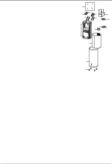
PREPARATION OF THE FRAME FOR THE HOOD IN RE-
CYCLING VERSION
In case the hood is used in recycling version it is necessary to prepare the frame with all the necessary connection pieces. In order to make the installation easier it is necessary to lengthen the frame:
•Unscrew the two screws 2.1 fixing the upper chimney to the frame and pull the chimney out.
•Unscrew the four safety screws placed at the top in the frame separation area. (A).
•Unscrew the eight metric screws connecting the two columns, placed on both sides of the frame (B).
Installation of components in recycling version:
•Fix the recycling air outlet piece 15 to the upper part of the frame using four 12c screws supplied with the hood.
•Fix the flange (ø120) 10 to the lower part of the recycling air outlet 15.
•Put the reducer flange 9 on the hood body outlet.
•At this point, join the flanges with a pipe. In order to calculate the height of the pipe it is necessary to estimate the height of the hood (mm) and subtract 615 mm. (H pipe = H hood-615).
•Lengthen the frame so that the pipe can be inserted. Place the pipe between the two flanges and block it. Make sure that the height of the frame is correct considering the height of the cooker hood (H frame = H hood – 184). Adjust the height of the frame and tighten again the earlier removed screws. Tighten again the safety screws in order to give more stability to the structure.
•Fix the pipe with the pipe clamps 25 supplied with the hood.
A
B
12c
15
10
EN |
|
7 |
|
7 |
 Loading...