


Instructions Manual Manuel d’Instructions Bedienungsanleitung Manual de instrucciones
Εγχειρίδιο οδηγιών
Руководство по эксплуатации
Kullanim Kilavuzu Naudojimosi instrukcija Instrukcijas Grāmata Kasutusjuhend

INDEX |
EN |
RECOMMENDATIONS AND SUGGESTIONS ..................................................................................................................... |
4 |
CHARACTERISTICS ............................................................................................................................................................. |
7 |
INSTALLATION...................................................................................................................................................................... |
8 |
USE ...................................................................................................................................................................................... |
11 |
MAINTENANCE ................................................................................................................................................................... |
12 |
SOMMAIRE |
FR |
CONSEILS ET SUGGESTIONS.......................................................................................................................................... |
15 |
CARACTERISTIQUES......................................................................................................................................................... |
18 |
INSTALLATION.................................................................................................................................................................... |
19 |
UTILISATION ....................................................................................................................................................................... |
22 |
ENTRETIEN ......................................................................................................................................................................... |
23 |
INHALTSVERZEICHNIS |
DE |
EMPFEHLUNGEN UND HINWEISE ................................................................................................................................... |
26 |
CHARAKTERISTIKEN ......................................................................................................................................................... |
29 |
MONTAGE ........................................................................................................................................................................... |
30 |
BEDIENUNG ........................................................................................................................................................................ |
33 |
WARTUNG........................................................................................................................................................................... |
34 |
ÍNDICE |
ES |
CONSEJOS Y SUGERENCIAS........................................................................................................................................... |
37 |
CARACTERÍSTICAS ........................................................................................................................................................... |
40 |
INSTALACIÓN ..................................................................................................................................................................... |
41 |
USO...................................................................................................................................................................................... |
44 |
MANTENIMIENTO ............................................................................................................................................................... |
45 |
ΠΕΡΙΕΧΟΜΕΝΑ |
GR |
ΣΥΜΒΟΥΛΕΣ ΚΑΙ ΣΥΣΤΑΣΕΙΣ............................................................................................................................................ |
48 |
ΧΑΡΑΚΤΗΡΙΣΤΙΚΑ............................................................................................................................................................... |
51 |
ΕΓΚΑΤΑΣΤΑΣΗ.................................................................................................................................................................... |
52 |
ΧΡΗΣΗ................................................................................................................................................................................. |
55 |
ΣΥΝΤΗΡΗΣΗ........................................................................................................................................................................ |
56 |
УКАЗАТЕЛЬ |
RU |
СОВЕТЫ И РЕКОМЕНДАЦИИ.......................................................................................................................................... |
59 |
ХАРАКТЕРИСТИКИ............................................................................................................................................................ |
62 |
УСТАНОВКА........................................................................................................................................................................ |
63 |
ЭКСПЛУАТАЦИЯ................................................................................................................................................................ |
66 |
УХОД.................................................................................................................................................................................... |
67 |
2

IÇERIKLER |
TR |
TAVSIYELER VE ÖNERILER.............................................................................................................................................. |
70 |
ÖZELLIKLER........................................................................................................................................................................ |
73 |
MONTAJ............................................................................................................................................................................... |
74 |
KULLANIM ........................................................................................................................................................................... |
77 |
BAKIM .................................................................................................................................................................................. |
78 |
TURINYS |
LT |
PATARIMAI IR NUORODOS............................................................................................................................................... |
81 |
PRIETAISO APRAŠYMAS .................................................................................................................................................. |
84 |
MONTAVIMAS ..................................................................................................................................................................... |
85 |
NAUDOJIMAS...................................................................................................................................................................... |
88 |
VALYMAS IR PRIEŽIŪRA ................................................................................................................................................... |
89 |
INDEKSS |
LV |
IETEIKUMI UN PRIEKŠLIKUMI........................................................................................................................................... |
92 |
TEHNISKIE DATI ................................................................................................................................................................. |
95 |
UZSTĀDĪŠANA .................................................................................................................................................................... |
96 |
IZMANTOŠANA ................................................................................................................................................................... |
99 |
APKOPE............................................................................................................................................................................. |
100 |
INDEKS |
EE |
SOOVITUSED JA ETTEPANEKUD................................................................................................................................... |
103 |
OMADUSED....................................................................................................................................................................... |
106 |
PAIGALDAMINE ................................................................................................................................................................ |
107 |
KASUTAMINE.................................................................................................................................................................... |
110 |
HOOLDUS.......................................................................................................................................................................... |
111 |
3
RECOMMENDATIONS AND SUGGESTIONS
The Instructions for Use apply to several versions of this appliance. Accordingly, you may find descriptions of individual features that do not apply to your specific appliance.
INSTALLATION
•The manufacturer will not be held liable for any damages resulting from incorrect or improper installation.
•The minimum safety distance between the cooker top and the extractor hood is 650 mm (some models can
be installed at a lower height, please refer to the paragraphs on working dimensions and installation).
• Check that the mains voltage corresponds to that indicated on the rating plate fixed to the inside of the hood.
• For Class I appliances, check that the domestic power supply guarantees adequate earthing.
Connect the extractor to the exhaust flue through a pipe of minimum diameter 120 mm. The route of the flue must be as short as possible.
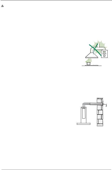
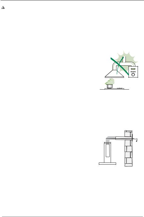
•Do not connect the extractor hood to exhaust ducts carrying combustion fumes (boilers, fireplaces, etc.).
•If the extractor is used in conjunction with non-
electrical appliances (e.g. gas burning |
|
appliances), a sufficient degree of aeration must |
2° |
be guaranteed in the room in order to prevent the |
|
backflow of exhaust gas. The kitchen must have |
|
an opening communicating directly with the open |
|
air in order to guarantee the entry of clean air. |
|
When the cooker hood is used in conjunction with |
|
appliances supplied with energy other than electric, the negative pressure in the room must not exceed 0,04 mbar to prevent fumes being drawn back into the room by the cooker hood.
•In the event of damage to the power cable, it must be replaced by the manufacturer or by the technical service department, in order to prevent any risks.
EN |
|
44 |
•If the instructions for installation for the gas hob specify a greater distance specified above, this has to be taken into account. Regulations concerning the discharge of air have to be fulfilled.
•Use only screws and small parts in support of the hood.
Warning: Failure to install the screws or fixing device in accordance with these instructions may result in electrical hazards.
•Connect the hood to the mains through a two-pole switch having a contact gap of at least 3 mm.
USE
•The extractor hood has been designed exclusively for domestic use to eliminate kitchen smells.
•Never use the hood for purposes other than for which it has been designed.
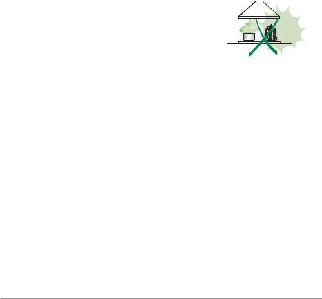
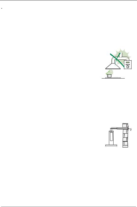
•Never leave high naked flames under the hood when it is in operation.
•Adjust the flame intensity to direct it onto the bottom of the pan only, making sure that it does not engulf the sides.
•Deep fat fryers must be continuously monitored during use: overheated oil can burst into flames.
• Do not flambè under the range hood; risk of fire.
• This appliance can be used by children aged from 8 years and above and persons with reduced
physical, sensory or mental capabilities or lack of
experience and knowledge if they have been given supervision or instruction concerning use of the appliance in a safe way and understand the hazards involved. Children shall not play with the appliance. Cleaning and user maintenance shall not be made by children without supervision.
EN |
|
55 |

•“CAUTION: Accessible parts may become hot when used with cooking appliances.”
MAINTENANCE
•Switch off or unplug the appliance from the mains supply before carrying out any maintenance work.
•Clean and/or replace the Filters after the specified time period (Fire hazard).
•The Grease filters must be cleaned every 2 months of operation, or more frequently for particularly heavy usage, and can be washed in a dishwasher.
•The Activated charcoal filter is not washable and cannot be regenerated, and must be replaced approximately every 4 months of operation, or more frequently for particularly heavy usage.
•"Failure to carry out cleaning as indicated will result in a fire hazard".
•Clean the hood using a damp cloth and a neutral liquid detergent.
The symbol  on the product or on its packaging indicates that this product may not be treated as household waste. Instead it shall be handed over to the applicable collection point for the recycling of electrical and electronic equipment. By ensuring this product is disposed of correctly, you will help prevent potential negative consequences for the environment and human health, which could otherwise be caused by inappropriate waste handling of this product. For more detailed information about recycling of this product, please contact your local city office, your household waste disposal service or the shop where you purchased the product.
EN |
|
66 |

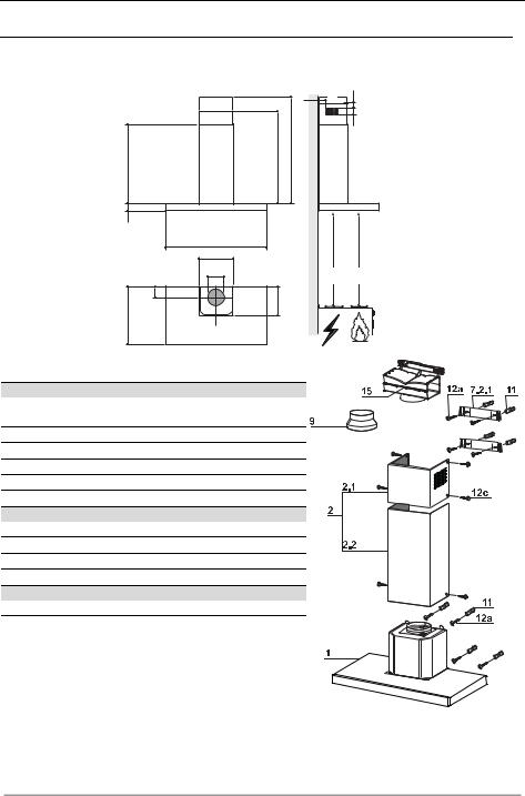
CHARACTERISTICS |
|
|
||
|
|
Dimensions |
|
|
|
|
|
64 |
<![if ! IE]> <![endif]>42 |
|
|
|
|
|
|
|
|
|
<![if ! IE]> <![endif]>81 |
|
|
|
<![if ! IE]> <![endif]>1000 |
|
|
|
<![if ! IE]> <![endif]>545 |
<![if ! IE]> <![endif]>730 |
|
|
|
<![if ! IE]> <![endif]>45 |
|
|
|
|
598-698-798-898-1198 |
|
|
|
|
300 |
|
|
|
|
150 |
Min. |
Min. |
|
|
650mm |
650mm |
|
|
|
|
||
|
|
<![if ! IE]> <![endif]>108 |
<![if ! IE]> <![endif]>260 |
|
|
|
<![if ! IE]> <![endif]>470 |
|
|
|
|
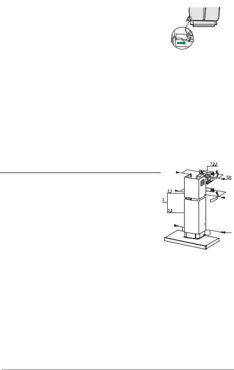
Components |
|
|
Ref. |
Q.ty |
Product Components |
|
|
1 |
1 |
Hood Body, complete with: Controls, Light, Blower, |
|
|
2 |
|
Filters |
|
|
1 |
Telescopic Chimney comprising: |
|
|
|
2.1 |
1 |
Upper Section |
|
|
2.2 |
1 |
Lower Section |
|
|
9 |
1 |
Reducer Flange ø 150-120 mm |
|
|
15 |
1 |
Air Outlet Connection |
|
|
Ref. |
Q.ty |
Installation Components |
|
|
7.2.1 |
2 |
Upper Chimney Section Fixing Brackets |
|
|
11 |
6 |
Wall Plugs |
|
|
12a |
6 |
Screws 4,2 x 44,4 |
|
|
12c |
6 |
Screws 2,9 x 9,5 |
|
|
|
Q.ty |
Documentation |
|
12b |
|
1 |
Instruction Manual |
|
|
EN |
|
77 |
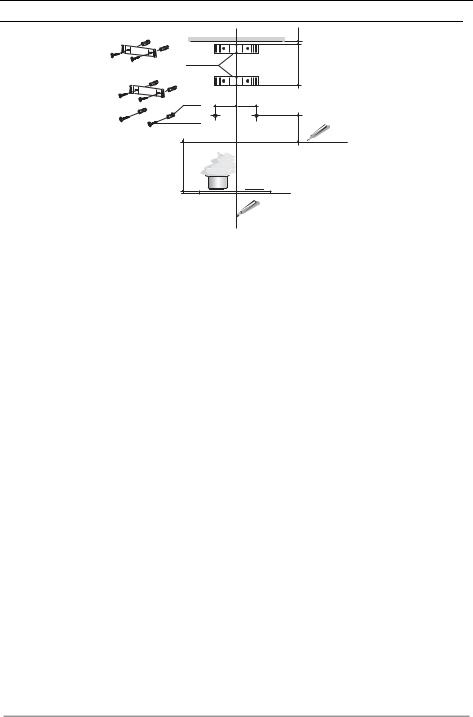
INSTALLATION
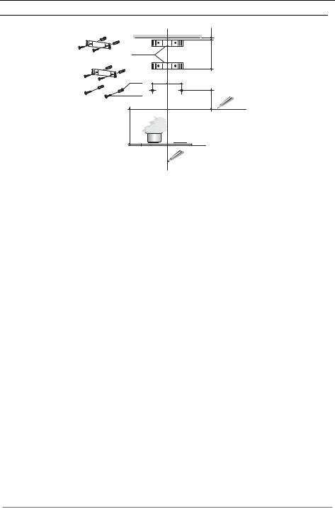
Wall drilling and bracket fixing
7.2.1
11 |
116 116 |
12a |
|
<![endif]>650 min.
<![endif]>X 1÷2
<![if ! IE]><![endif]>305
Wall marking:
•Draw a vertical line on the supporting wall up to the ceiling, or as high as practical, at the centre of the area in which the hood will be installed.
•Draw a horizontal line at 650 mm above the hob. Place bracket 7.2.1 on the wall as shown about 1-2 mm from the ceiling or upper limit aligning the centre (notch) with the vertical reference line.
•Mark the wall at the centres of the holes in the bracket.
•Place bracket 7.2.1 on the wall as shown at X mm below the first bracket (X = height of the upper chimney section supplied), aligning the centre (notch) with the vertical line.
•Mark the wall at the centres of the holes in the bracket.
•Mark a reference point as indicated at 116 mm from the vertical reference line and 305 mm above the horizontal reference line.
•Repeat this operation on the other side.
•Drill ø 8 mm holes at all the centre points marked.
•Insert the wall plugs 11 in the holes.
•Fix the brackets using the 12a (4,2 x 44,4) screws supplied.
•Insert the two screws 12a (4,2 x 44,4) supplied in the hood body fixing holes, leaving a gap of 5-6 mm between the wall and the head of the screw.
EN |
|
88 |
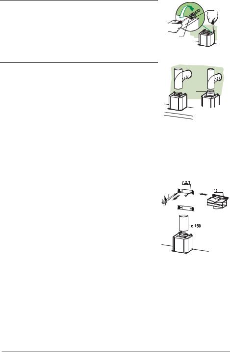
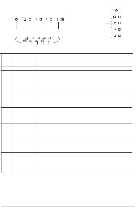
Mounting the hood body
• Before attaching the hood body, tighten the two screws Vr lo-
Vr
cated on the hood body mounting points.
• Hook the hood body onto the screws 12a.
• Fully tighten the support screws 12a.
• Adjust the screws Vr to level the hood body. |
12a |
|
Connections |
|
|
|
|
DUCTED VERSION AIR EXHAUST SYSTEM |
|
|
|
When installing the ducted version, connect the hood to the |
|
|
||
chimney using either a flexible or rigid pipe ø 150 or 120 mm, |
ø 150 |
ø 120 |
||
the choice of which is left to the installer. |
||||
|
9 |
|||
• |
To install a ø 120 mm air exhaust connection, insert the re- |
|
||
|
|
|||
|
ducer flange 9 on the hood body outlet. |
|
|
|
• |
Fix the pipe in position using sufficient pipe clamps (not sup- |
|
|
|
|
plied). |
|
|
|
• Remove possible charcoal filters.
AIR OUTLET – RECIRCULATION VERSION
• Unfasten the 2 screws fixing the upper bracket 7.2.1.
• Fasten the air outlet connector 15 in its place, using the 2  screws removed as above.
• Join the Connector 15 to the Hood canopy outlet using a rigid or flexible pipe ø150 mm, selection of which is at the
discretion of the installation technician.
• Make sure that the Activated charcoal odour filter has been fitted.
EN |
|
99 |
ELECTRICAL CONNECTION
•Connect the hood to the mains through a two-pole switch having a contact gap of at least 3 mm.
•Remove the grease filters (see paragraph Maintenance) being sure that the connector of the feeding cable is correctly inserted in the socket placed on the side of the fan.
Flue assembly
Upper exhaust flue
•Slightly widen the two sides of the upper flue and hook them behind the brackets 7.2.1, making sure that they are well seated.
•Secure the sides to the brackets by using the 4 screws 12c (2,9 x 9,5) supplied.
•Make sure that the outlet of the extensions pieces is aligned with the chimney outlets.
Lower exhaust flue
• Slightly widen the two sides of the flue and hook them between the upper flue and the wall, making sure that they are well seated.
•Fix the lower part laterally to the hood body by using the 2 screws 12c (2,9 x 9,5) supplied.
12b |
EN |
|
1 |
|
10 |
USE
|
|
|
|
|
|
|
|
L |
|
|
|
|
|
|
|
S1 |
T1 |
|
|
|
|
|
|
|
|
|
|
|
|
|
|
|
|
|
T2 |
L |
T1 |
|
T2 |
|
T3 |
T4 |
|
T3 |
|
|
|
|
|||||
|
S1 |
|
|
|
|
|
|
T4 |
|
|
|
|
|
|
|
|
S1 |
|
L |
T1 |
T2 |
T3 |
T4 |
|
|
|
Control panel
Button Led
L -
T1 Fixed
T2 Fixed
T3 Fixed
T4 Fixed
S1 Fixed
Flashing
Function
Turns the lights on/off at maximum strength. Turns the motor on/off at speed one.
Turns the Motor on at speed two.
Press and hold the button for approximately 3 seconds, with all the loads turned off (Motor and Lights), to turn the Activated Charcoal Filter alarm on. The relevant LED flashes twice to confirm.
To turn the alarm off, press the button again and hold for at least 3 seconds. The relevant LED flashes once.
Turns the Motor on at speed three.
Press and hold the button for approximately 3 seconds, with all the loads turned off (Motor and Lights), to perform a reset of Filter saturation alarm. The LED S1 flashes three times.
Turns the Motor on at INTENSIVE Speed.
This speed is timed to run for 6 minutes. At the end of this time, the system returns automatically to the speed that was set before. If it is activated with the motor turned off, the hood will switch to OFF at the end of the time.
Press and hold for 3 seconds to enable the remote control, indicated by the LED flashing twice.
Press and hold for 3 seconds to disable the remote control, indicated by the LED flashing just once.
Signals the Metal Grease Filter saturation alarm, indicating that it is necessary to wash the filters. The alarm is triggered after the Hood has been in operation for 100 working hours. (Reset see the parag. Maintenance)
When this is activated, it signals the Activated Charcoal Filter saturation alarm, indicating that the filter must be changed; the Metal Grease Filters must also be washed. The Activated Charcoal Filter saturation alarm comes
into operation after the Hood has been working for 200 hours. (Activation and Reset see the parag. Maintenance)
EN |
|
1 |
|
11 |
MAINTENANCE
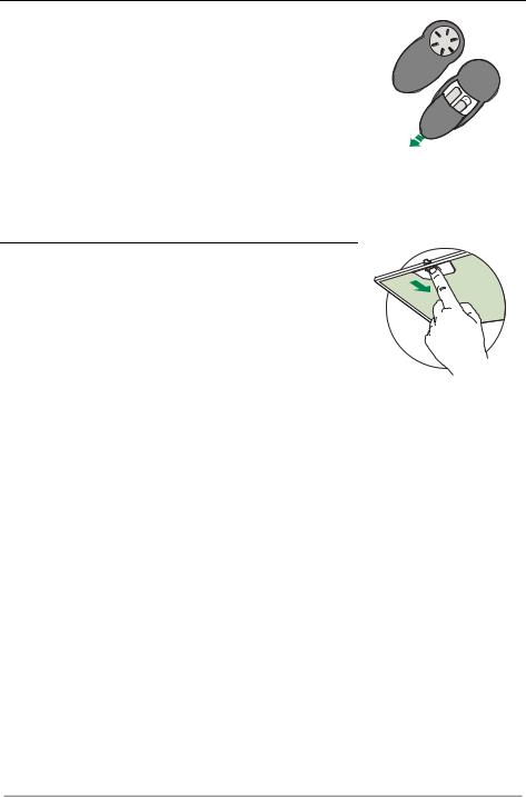
REMOTE CONTROL (OPTIONAL)
The appliance can be controlled using a remote control powered by a 1.5 V carbon-zinc alkaline batteries of the standard LR03AAA type (not included).
•Do not place the remote control near to heat sources.
•Used batteries must be disposed of in the proper manner.
Metal grease filters
These can be washed in the dishwasher, and need to be cleaned whenever the S1 Led comes on or at least once every 2 months use, or more frequently if use is particularly intensive.
CLEANING THE FILTERS
Resetting the alarm signal
•Turn the Lights and the Suction Motor off.
•Press T3 and hold for at least 3 seconds, until LED flashes three times in confirmation.
Cleaning the Filters
•Remove the Filter, pushing it towards the back of the unit and at the same time pulling downward.
•Wash the filter without bending it, and leave it to dry thoroughly before replacing (if the surface of the filter changes colour over time, this will have absolutely no effect on its efficiency).
•Replace, taking care to ensure that the handle faces forwards.
EN |
|
1 |
|
12 |

Activated Charcoal Filter (Recirculation Version)
This cannot be washed or regenerated, and must be changed when led S1 starts to flash, or at least once every 4 months. The Alarm signal, if it has been activated, only appears when the Suction motor is turned on.
Activating the alarm signal
•In Recirculation Version Hoods, the Filter Saturation Alarm must be activated on installation or at a later date.
•Turn the Lights and the Suction Motor off.
•Press button T2 and hold it for 5 seconds until the LED flashes twice in confirmation:
CHANGING
Resetting the alarm signal
•Turn the Lights and the Suction Motor off.
•Press T3 and hold for at least 3 seconds, until LED flashes
three times in confirmation.
Changing the Filter
• Remove the Metal Grease Filter
• Remove the saturated Activated charcoal filter, using the hooks provided.
•Fit the new Filter, hooking it into place.
•Fit the Grease filter.
EN |
|
1 |
|
13 |

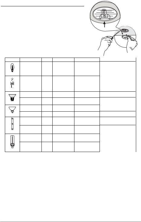
Lighting
LIGHT REPLACEMENT
20 W halogen light.
•Remove the snap-on lamp cover by levering it from under the metal ring, supporting it with one hand.
•Remove the halogen lamp from the lamp holder by pulling gently.
•Replace the lamp with a new one of the same type, making sure that you insert the two pins properly into the housings on the lamp holder.
•Replace the snap-on lamp cover.
Lamp |
Power (W) |
Socket |
Voltage (V) |
Dimension (mm) |
ILCOS Code |
|
28 |
E14 |
220 – 240 |
104 x 35 |
HSGSB/C/UB-28-220/240-E14 |
|
20 |
G4 |
12 |
33 x 9 |
HSG/C/UB-20-12-G4 |
|
35 |
GU10 |
230 |
51 x 50,7 |
HAGS-35-230-GU10-51/40 |
|
50 |
GU10 |
230 |
51 x 50,7 |
HAGS-35-230-GU10-51/20 |
|
20 |
GU4 |
12 |
40 x 35 |
HRGS-20-12-GU4-35/30 |
|
20 |
GU5.3 |
12 |
46 x 51 |
HRGS-20-12-GU5.3-50/10 |
|
16 |
G13 |
95 |
720 x 26 |
FD--16/40/1B-E--G13--26/720 |
|
18 |
G13 |
57 |
589,8 x 26 |
FD--18/40/1B--E--G13--26/600 |
|
9 |
G23 |
60 (lamp) |
167 x 28 |
FSD-9/27/1B-I-G23 |
|
220-240 (starter) |
||||
|
|
|
|
|
|
|
11 |
G23 |
91 (lamp) |
235,8 x 28 |
FSD-11/40/1B-I-G23 |
|
220-240 (starter) |
||||
|
|
|
|
|
EN |
|
1 |
|
14 |
CONSEILS ET SUGGESTIONS
 Les instructions pour l’utilisation se réfèrent aux différents modèles de cet appareil. Par conséquent, certaines descriptions de caractéristiques particulières pourraient ne pas appartenir spécifiquement à cet appareil.
INSTALLATION
•En aucun cas le fabricant ne peut être tenu pour responsable d’éventuels dommages dus à une installation ou à une utilisation impropre.
•La distance de sécurité minimum entre le plan de cuisson et la hotte aspirante est de 650 mm (certains
modèles peuvent être installés à une hauteur inférieure ; voir le paragraphe concernant les dimensions de travail et l’installation).
• Assurez-vous que la tension de votre secteur correspond à celle indiquée sur la plaque des données appliquée à l’intérieur de la hotte.
•Pour les appareils de Classe I, s’assurer que l’installation électrique de votre intérieur dispose d’une mise à la terre adéquate.
Relier l’aspirateur au conduit de cheminée avec un tube d’un diamètre minimum de 120 mm. Le parcours des fumées doit être le plus court possible.
•Ne pas relier la hotte aspirante aux conduits de cheminée qui acheminent les fumées de combustion (par exemple de chaudières, de cheminées, etc.).
•Si vous utilisez l’aspirateur en combinaison avec des
appareils non électriques (par ex. appareils à gaz), vous |
2° |
devez garantir un degré d’aération suffisant dans la pièce, |
|
afin d’empêcher le retour du flux des gaz de sortie. La |
|
cuisine doit présenter une ouverture communiquant |
|
directement vers l’extérieur pour garantir l’amenée d’air |
|
propre. Si vous utilisez la hotte de cuisine en combinaison avec des appareils |
|
non alimentés à l’électricité, la pression négative dans la pièce ne doit pas |
|
dépasser 0,04 mbar afin d’éviter que la hotte ne réaspire les fumées dans la |
|
pièce. |
|
•Si le cordon d’alimentation est endommagé, veuillez le faire remplacer par le fabricant ou par un service après-vente agréé pour éviter tout risque d’accident.
FR |
|
1 |
|
15 |

•Si les instructions d’installation du plan de cuisson à gaz spécifient une distance supérieure à celle indiquée ci-dessus, veuillez impérativement en tenir compte. Toutes les normes concernant l’évacuation de l’air doivent être respectées.
•Utiliser exclusivement des vis et des petites pièces du type adapté pour la hotte.
Attention : toute installation des vis et des dispositifs de fixation non conforme aux présentes instructions peut entraîner des risques de décharges électriques.
•Brancher la hotte à l’alimentation de secteur avec un interrupteur bipolaire ayant une ouverture des contacts d’au moins 3 mm.
UTILISATION
•Cette hotte aspirante a été conçue exclusivement pour un usage domestique, dans le but d’éliminer les odeurs de cuisine.
•Ne jamais utiliser la hotte pour des objectifs différents de ceux pour lesquels elle a été conçue.
•Ne jamais laisser un feu vif allumé sous la hotte lorsque celle-ci est en fonction.
•Régler l’intensité du feu de manière à l’orienter exclusivement vers le fond de la casserole, en vous assurant qu’il ne déborde pas sur les côtés.
•Contrôler constamment les friteuses durant leur utilisation : l’huile surchauffée risque de s’incendier.
•Ne pas flamber des mets sous la hotte : sous risque de provoquer un incendie.
•Cet appareil n’est pas destiné à être utilisé par des
enfants d’un âge inférieur à 8 ans, ni par des personnes dont les capacités physiques, sensorielles ou mentales sont diminuées ou qui ont une expérience et des connaissances insuffisantes, à moins que ces enfants ou ces personnes ne soient attentivement surveillés et instruits sur la manière d’utiliser cet appareil en sécurité et sur les dangers que cela comporte. Assurez-vous que les enfants ne jouent pas avec cet appareil. Le nettoyage et l’entretien de la part de l’utilisateur ne doivent pas être effectués par des enfants, à moins que ce ne soit sous la surveillance d’une personne responsable.
FR |
|
1 |
|
16 |

•ATTENTION : les parties accessibles peuvent devenir très chaudes durant l’utilisation des appareils de cuisson.
ENTRETIEN
•Avant d’effectuer toute opération de nettoyage et d’entretien, éteindre ou débrancher l’appareil du secteur.
•Nettoyer et/ou remplacer les filtres après le délai indiqué (danger d’incendie).
•Nettoyer les filtres à graisse tous les 2 mois de fonctionnement ou plus souvent en cas d’utilisation particulièrement intense. Ces filtres peuvent être lavés au lave-vaisselle.
•Le filtre à charbon actif ne peut être ni lavé ni régénéré et il doit être remplacé environ tous les 4 mois de fonctionnement ou plus souvent en cas d’utilisation particulièrement intense.
•Effectuer le nettoyage selon les instructions, sous risque d'incendie.
•Nettoyer la hotte avec un chiffon humide et un détergent liquide neutre.
Le symbole  marqué sur le produit ou sur son emballage indique que ce produit ne peut pas être éliminé comme déchet ménager normal. Lorsque ce produit doit être éliminé, veuillez le remettre à un centre de collecte prévu pour le recyclage du matériel électrique et électronique. En vous assurant que cet appareil est éliminé correctement, vous participez à prévenir des conséquences potentiellement négatives pour l'environnement et pour la santé, qui risqueraient de se présenter en cas d’élimination inappropriée. Pour toute information supplémentaire sur le recyclage de ce produit, contactez votre municipalité, votre déchetterie locale ou le magasin où vous avez acheté ce produit.
FR |
|
1 |
|
17 |

CARACTERISTIQUES |
|
|
||
|
|
Encombrement |
|
|
|
|
|
64 |
<![if ! IE]> <![endif]>42 |
|
|
|
|
|
|
|
|
|
<![if ! IE]> <![endif]>81 |
|
|
|
<![if ! IE]> <![endif]>1000 |
|
|
|
<![if ! IE]> <![endif]>545 |
<![if ! IE]> <![endif]>730 |
|
|
|
<![if ! IE]> <![endif]>45 |
|
|
|
|
598-698-798-898-1198 |
|
|
|
|
300 |
|
|
|
|
150 |
Min. |
Min. |
|
|
650mm |
650mm |
|
|
|
|
||
|
|
<![if ! IE]> <![endif]>108 |
<![if ! IE]> <![endif]>260 |
|
|
|
<![if ! IE]> <![endif]>470 |
|
|
|
|
Composants |
|
|
Réf. |
Q.té |
Composants de Produit |
|
|
1 |
1 |
Corps Hotte équipé de:Commandes, Lumière, Groupe |
|
|
2 |
|
Ventilateur,Filtres |
|
|
1 |
Cheminée Télescopique formée de : |
|
|
|
2.1 |
1 |
Cheminée Supérieure |
|
|
2.2 |
1 |
Cheminée Inférieure |
|
|
9 |
1 |
Flasque de Réduction ø 150-120 mm |
|
|
15 |
1 |
Raccord Sortie Air |
|
|
Réf. |
Q.té |
Composants pour l ’installation |
|
|
7.2.1 |
2 |
Brides Fixation Cheminée Supérieure |
|
|
11 |
6 |
Chevilles |
|
|
12a |
6 |
Vis 4,2 x 44,4 |
|
|
12c |
6 |
Vis 2,9 x 9,5 |
|
|
|
Q.té |
Documentation |
|
12b |
|
1 |
Manuel d’instructions |
|
|
FR |
|
1 |
|
18 |

INSTALLATION
Perçage Paroi et Fixation Brides
7.2.1
11 |
116 116 |
12a |
|
<![endif]>650 min.
<![endif]>X 1÷2
<![if ! IE]><![endif]>305
Tracer sur la paroi:
•une ligne verticale allant jusqu’au plafond ou à la limite supérieure, au centre de la zone prévue pour le montage de la hotte;
•une ligne horizontale à 650 mm min. au-dessus du plan de cuisson.
•Poser comme indiqué une bride 7.2.1 sur la paroi à 1-2 mm du plafond ou de la limite supérieure, en alignant son centre (découpes) sur la ligne verticale de repère.
•Marquer les centres des trous rainurés de la bride.
•Poser comme indiqué la bride 7.2.1 à X mm sous la première bride (X = hauteur cheminée supérieure fournie), en alignant son centre (découpes) sur la ligne verticale de repère.
•Marquer les centres des trous rainurés de la bride.
•Marquer comme indiqué, un point de référence à 116 mm de la ligne verticale de repère, et 305 mm au-dessus de la ligne horizontale de repère.
•Répéter cette opération sur le côté opposé.
•Percer de ø 8 mm tous les points marqués.
•Insérer les chevilles 11 dans les trous.
•Fixer les brides en utilisant les vis 12a (4,2 x 44,4) fournies.
•Visser les 2 vis 12a (4,2 x 44,4) fournies dans les trous de fixation du corps hotte, en laissant un espace de 5-6 mm entre le mur et la tête de la vis.
FR |
|
1 |
|
19 |

Montage Corps Hotte
• Avant d’accrocher le corps hotte, serrer les deux vis Vr situées |
Vr |
sur les points d’accrochage du corps hotte. |
|
• Accrocher le corps hotte aux vis 12a prévues à cet effet. |
|
• Serrer définitivement les vis 12a de support. |
|
• Agir sur les vis Vr pour niveler le corps hotte. |
12a |
Branchements |
|
|
|
SORTIE AIR VERSION ASPIRANTE |
|
|
|
Pour l’installation en version aspirante, relier la hotte au tube de |
|
|
|
sortie au moyen d’un tube rigide ou flexible de ø 150 ou 120 mm |
ø 150 |
ø 120 |
|
dont le choix est laissé à l’installateur. |
|||
|
9 |
||
• Pour la liaison avec le tube ø120 mm, insérer la buse de réduc- |
|
|
|
tion 9 sur la sortie du corps de la hotte. |
|
|
|
• Fixer le tube avec des colliers serre-tube appropriés. Le |
|
|
|
matériel nécessaire n’est pas fourni. |
|
|
|
• Retirer les filtres anti-odeur à charbon actif éventuels. |
|
|
SORTIE AIR VERSION FILTRANTE
• Desserrer les 2 vis de fixation du support supérieur 7.2.1.
• Visser à sa place le raccord de sortie de l’air 15 avec les 2 vis précédemment retirées.
•Relier le raccord 15 à la sortie du corps de hotte au moyen d’un tube rigide ou flexible de ø 150 mm, au choix de l'installateur.
• S’assurer de la présence du filtre anti-odeur au charbon actif.
FR |
|
2 |
|
20 |
BRANCHEMENT ELECTRIQUE
•Brancher la hotte sur le secteur en interposant un interrupteur bipolaire avec ouverture des contacts d’au moins 3 mm.
•Enlever les filtres à graisse (voir § "Entretien") et s'assurer que le connecteur du câble d'alimentation soit bien branché dans la prise du diffuseur.
Montage Cheminée
Cheminée supérieure
•Elargir légèrement les deux bords latéraux, et les accrocher derrières les brides 7.2.1 ; refermer jusqu’en butée.
•Fixer latéralement aux brides à l’aide des 4 vis 12c fournies.
•S’assurer que la sortie des rallonges raccord se trouve au niveau des bouches de la cheminée.
Cheminée inférieure
•Elargir légèrement les deux bords latéraux de la cheminée et les accrocher entre la cheminée supérieure et la paroi; refermer jusqu’en butée.
•Fixer latéralement la partie inférieure au corps de la hotte, à l’aide des deux 2 vis 12c fournies.
12b |
FR |
|
2 |
|
21 |
UTILISATION
|
|
|
|
|
|
|
|
|
|
|
|
|
|
|
|
|
S1 |
L |
|
|
|
|
||||||
|
|
|
|
|
|
|
|
|
|
|
|
|
|
|
|
|
|
|
|
|
|
|
|
|
|
|
||
|
|
|
|
|
|
|
|
|
|
|
|
|
|
|
|
|
T1 |
|
|
|
|
|
|
|
|
|
||
|
|
|
|
|
|
|
|
|
|
|
|
|
|
|
|
|
|
|
|
|
|
|
|
|
|
|
||
|
|
|
|
|
|
|
|
|
|
|
|
|
|
|
|
|
|
|
|
|
|
|
|
|
|
|
|
|
|
|
|
|
|
|
|
|
|
|
|
|
|
|
|
|
|
|
|
T2 |
|
|
|
|
|
|
|
|
|
|
|
|
|
|
|
|
|
|
|
|
|
|
|
|
|
|
|
|
|
|
|
|
||||||
|
L |
T1 |
|
T2 |
|
T3 |
|
|
T4 |
T3 |
|
|
|
|
|
|||||||||||||
|
|
|
|
|
|
|
|
|||||||||||||||||||||
|
|
|
|
|
|
|
|
|
|
|
|
|
|
|
||||||||||||||
|
|
|
|
|
S1 |
|
|
|
|
|
|
|
|
|
|
|
|
|
T4 |
|
|
|
|
|
|
|
|
|
|
|
|
|
|
|
|
|
|
|
|
|
|
|
|
|
|
|
|
|
|
|
|
|
|
|
|
|
|
|
|
|
|
|
|
|
|
|
|
|
|
|
|
|
|
|
|
|
S1 |
|
|
|
|
|
|
|||
|
|
|
|
|
|
|
|
|
|
|
|
|
|
|
|
|
|
|
|
|
|
|
|
|
||||
|
|
|
|
L |
T1 |
T2 |
T3 T4 |
|
|
|
|
|
|
|
|
|
|
|||||||||||
|
|
|
|
|
|
|
|
|
|
|
|
|
|
|||||||||||||||
Touche |
Led |
|
|
|
|
Fonction |
Tableau de commande |
|
|
|
|
|
|
|
|
|
|
|||||||||||
|
|
|
|
|
|
|
|
|
|
|
|
|
|
|
|
|
|
|
|
|||||||||
L |
- |
|
|
|
|
|
|
Allume/Éteint les lumières à la luminosité maximum. |
|
|
|
|
|
|
|
|
|
|
||||||||||
T1 |
Fixe |
|
|
|
|
Démarre/Coupe le moteur à la première vitesse. |
|
|
|
|
|
|
|
|
|
|
||||||||||||
T2 |
Fixe |
|
|
|
|
Démarre le moteur à la deuxième vitesse. |
|
|
|
|
|
|
|
|
|
|
||||||||||||
|
|
|
|
|
|
|
|
Garder la touche appuyée pendant environ 5 secondes, lorsque toutes les |
||||||||||||||||||||
|
|
|
|
|
|
|
|
charges sont éteintes (Moteur+ Éclairage), l’alarme des filtres au charbon |
||||||||||||||||||||
|
|
|
|
|
|
|
|
actif s’active et la led correspondante clignotera 2 fois. |
|
|
|
|
|
|
|
|
|
|
||||||||||
|
|
|
|
|
|
|
|
Pour la désactiver, appuyer de nouveau sur la touche pendant 5 secondes. |
||||||||||||||||||||
T3 |
|
|
|
|
|
|
|
La led correspondante clignotera 1 fois. |
|
|
|
|
|
|
|
|
|
|
||||||||||
Fixe |
|
|
|
|
Démarre le moteur à la troisième vitesse. |
|
|
|
|
|
|
|
|
|
|
|||||||||||||
|
|
|
|
|
|
|
|
Garder la touche appuyée pendant environ 3 secondes, lorsque toutes les |
||||||||||||||||||||
|
|
|
|
|
|
|
|
charges sont éteintes (Moteur+ Éclairage), le reset est effectué et la led S1 |
||||||||||||||||||||
T4 |
|
|
|
|
|
|
|
correspondante clignotera 3 fois. |
|
|
|
|
|
|
|
|
|
|
||||||||||
Fixe |
|
|
|
|
Démarre le moteur à la vitesse INTENSIVE. |
|
|
|
|
|
|
|
|
|
|
|||||||||||||
|
|
|
|
|
|
|
|
Cette vitesse est temporisée à 6 minutes. Après ce délai, Le système re- |
||||||||||||||||||||
|
|
|
|
|
|
|
|
tourne automatiquement à la vitesse sélectionnée. Si activée avec le moteur |
||||||||||||||||||||
|
|
|
|
|
|
|
|
à l’arrêt, à la fin du délai le système passe en mode OFF. |
||||||||||||||||||||
|
|
|
|
|
|
|
|
Garder la touche appuyée pendant environ 5 secondes pour valider la |
||||||||||||||||||||
|
|
|
|
|
|
|
|
télécommande. La led correspondante clignotera 2 fois. |
||||||||||||||||||||
|
|
|
|
|
|
|
|
Garder la touche appuyée pendant 5 secondes pour invalider la |
||||||||||||||||||||
S1 |
|
|
|
|
|
|
|
télécommande. La led correspondante clignotera 1 seule fois |
||||||||||||||||||||
Fixe |
|
|
|
|
Signale l’alarme saturation filtres à graisse métalliques et la nécessité de les |
|||||||||||||||||||||||
|
|
|
|
|
|
|
|
laver. L’alarme entre en fonction après 100 heures de travail effectif de la |
||||||||||||||||||||
|
|
|
|
|
|
|
|
hotte. (Reset voir paragraphe Entretien) |
|
|
|
|
|
|
|
|
|
|
||||||||||
|
Clignotante |
|
|
Lorsque l’alarme de saturation du filtre anti-odeur est activée, c’est l’indice |
||||||||||||||||||||||||
|
|
|
|
|
|
|
|
que le filtre doit être remplacé. Laver aussi les filtres à graisse métalliques. |
||||||||||||||||||||
|
|
|
|
|
|
|
|
L’alarme de saturation filtre anti-odeur au charbon actif entre en fonction |
||||||||||||||||||||
|
|
|
|
|
|
|
|
après 200 heures de travail effectif de la hotte. (Activation et Reset voir |
||||||||||||||||||||
|
|
|
|
|
|
|
|
paragraphe Entretien) |
|
|
|
|
|
|
|
|
|
|
||||||||||
FR |
|
2 |
|
22 |

ENTRETIEN
TELECOMMANDE (FOURNIE SUR DEMANDE)
Il est possible de commander cet appareil au moyen d’une télécommande, alimentée avec des piles alcalines zinc-charbon 1,5 V du type standard LR03-AAA (non compris).
•Ne pas ranger la télécommande à proximité de sources de chaleur.
•Ne pas jeter les piles; il faut les déposer dans les récipients de récolte spécialement prévus à cet effet.
Filtres à graisse métalliques
Ils peuvent être lavés au lave-vaisselle et doivent être lavés quand la led S1 s’allume ou au moins tous les 2 mois d’utilisation ou plus fréquemment en cas d’utilisation particulièrement intensive.
NETTOYAGE FILTRES
Reset du signal d'alarme
•Éteindre les lumières et le moteur d’aspiration.
•Appuyer sur la touche T3 pendant au moins 3 secondes jusqu’au triple clignotement de confirmation de la led.
Nettoyage filtres
•Retirer le filtre en le poussant vers l’arrière du groupe et en tirant en même temps vers le bas.
•Laver le filtre en évitant de le plier, et le laisser sécher avant de le remonter (tout changement de couleur de la surface du filtre, susceptible de se produire avec le temps, ne nuit en rien à l’efficacité de ce dernier).
•Le remonter en faisant attention de garder la poignée vers la partie visible externe.
FR |
|
2 |
|
23 |

Filtres anti-odeur à charbon actif (version filtrante)
Il n’est ni lavable, ni régénérable. Le remplacer lorsque la led S1 clignote ou au moins tous les 4 mois. Le signal d’alarme, si préalablement activé, se vérifie seulement lorsque le moteur d’aspiration est en marche.
Activation du signal d’alarme
•Dans les hottes en version filtrante, activer le signal d’alarme de saturation filtres au moment de l’installation ou après.
•Éteindre les lumières et le moteur d’aspiration.
•Appuyer pendant 5 secondes sur la touche T2 jusqu’à ce que la led de confirmation clignote :
REMPLACEMENT
Reset du signal d'alarme
•Éteindre les lumières et le moteur d’aspiration.
•Appuyer sur la touche T3 pendant au moins 3 secondes
jusqu’au triple clignotement de confirmation de la led.
Remplacement du filtre
• Retirer le filtre à graisse
• Retirer le filtre anti-odeur au charbon actif colmaté, en agissant sur les crochets prévus à cet effet.
•Monter le nouveau filtre anti-odeur au charbon actif.
•Remonter le filtre à graisse
FR |
|
2 |
|
24 |
Eclairage
REMPLACEMENT LAMPES
Lampe halogène de 20 W.
•Enlever le dispositif métallique de blocage du verre par encliquetage en exerçant une pression sous l’embout en le soutenant d’une main.
•Extraire la lampe du support
•Remplacer la lampe par une nouvelle ayant le mêmes caractéristiques, en prenant soin d'insérer correctement les deux fiches dans le support.
•Remonter le dispositif de blocage du verre par encliquetage.
Ampoule |
Absorption (W) |
Culot |
Voltage (V) |
Dimensions (mm) |
Code ILCOS |
|
28 |
E14 |
220 – 240 |
104 x 35 |
HSGSB/C/UB-28-220/240-E14 |
|
20 |
G4 |
12 |
33 x 9 |
HSG/C/UB-20-12-G4 |
|
35 |
GU10 |
230 |
51 x 50,7 |
HAGS-35-230-GU10-51/40 |
|
50 |
GU10 |
230 |
51 x 50,7 |
HAGS-35-230-GU10-51/20 |
|
20 |
GU4 |
12 |
40 x 35 |
HRGS-20-12-GU4-35/30 |
|
20 |
GU5.3 |
12 |
46 x 51 |
HRGS-20-12-GU5.3-50/10 |
|
16 |
G13 |
95 |
720 x 26 |
FD--16/40/1B-E--G13--26/720 |
|
18 |
G13 |
57 |
589,8 x 26 |
FD--18/40/1B--E--G13--26/600 |
|
9 |
G23 |
60 (ampoule) |
167 x 28 |
FSD-9/27/1B-I-G23 |
|
220-240 (starter) |
||||
|
|
|
|
|
|
|
11 |
G23 |
91 (ampoule) |
235,8 x 28 |
FSD-11/40/1B-I-G23 |
|
220-240 (starter) |
||||
|
|
|
|
|
FR |
|
2 |
|
25 |
EMPFEHLUNGEN UND HINWEISE
Diese Gebrauchsanleitungen beziehen sich auf die verschiedenen Modelle der Abzugshaube. Darum kann es möglich sein, dass die Beschreibung bestimmter Merkmale für das vorliegende Gerät nicht zutrifft.
INSTALLATION
•Der Hersteller haftet nicht für etwaige Schäden, die durch die fehlerhafte Installation oder falschen Gebrauch entstehen könnten.
•Der min. Sicherheitsabstand zwischen Kochfeld und Abzugshaube beträgt 650 mm (einige Modelle
können auch niedriger installiert werden; siehe Absatz Installation).
• Kontrollieren Sie, ob die Netzspannung den Daten des Typenschilds im Innern der Haube entspricht.
• Für Geräte der Klasse I muss kontrolliert werden, ob das häusliche Versorgungsnetz korrekt geerdet ist.
Die Absaughaube mit Hilfe eines Rohrs mit einem Mindestdurchmesser von 120 mm mit dem Rauchabzug verbinden. Der Verlauf des Rauchabzugs soll so kurz wie möglich sein.
•Die Abzugshaube darf nicht an einen Schacht angeschlossen werden, in den Rauchgase geleitet werden (z. B. von Heizkessel, Kaminen, usw.).
•Falls in dem Raum neben dem Abzug auch nicht
mit Strom betriebene Geräte (zum Beispiel |
|
Gasgeräte) eingesetzt werden, muss für eine |
2° |
ausreichende Belüftung gesorgt werden, damit der |
|
Rückfluss der Abgase verhindert wird. Die Küche |
|
muss eine direkte Öffnung nach Außen aufweisen, |
|
damit ein ausreichender Luftaustausch |
|
gewährleistet wird. Wird die Abzugshaube |
|
zusammen mit nicht mit Strom betriebenen Geräte eingesetzt, darf der |
|
Unterdruck im Raum 0,04 mbar nicht überschreiten, damit die Abgase nicht |
|
wieder angesaugt werden. |
|
•Schadhafte Kabel müssen durch den Hersteller oder vom Kundendienst ausgewechselt werden, damit jedes Risiko ausgeschlossen wird.
DE |
|
2 |
|
26 |

•Falls die Montageanweisungen für die gasbetriebene Kochmulde einen größeren Abstand vorschreiben, als der oben angegebene, muss diese Vorgabe befolgt werden. Es sind sämtliche Abluftvorschriften zu beachten.
•Nur für die Abzugshaube geeignete Schrauben und Kleinteile verwenden. Achtung: Werden die Schrauben und Befestigungselemente nicht entsprechend der vorliegenden Anleitungen verwendet, besteht Stromschlaggefahr.
•Die Abzugshaube mittels zweipoligem Schalter mit einer Öffnung der Kontakte von mindestens 3 mm an das Netz anschließen.
GEBRAUCH
•Die Abzugshaube wurde ausschließlich für den häuslichen Gebrauch entwickelt, um Kochdünste zu beseitigen.
•Die Haube darf nur für die ihr zugedachten Zwecke benutzt werden.
•Unter der eingeschalteten Haube keine offenen Flammen benutzen.
•Die Flamme so regulieren, dass sie nicht über den Boden des Kochgeschirrs hinausreicht.
•Fritteusen müssen während des Gebrauchs
ständig überwacht werden: überhitztes Öl könnte sich entzünden.
•Auf keinen Fall unter der Haube flambieren: Brandgefahr.
•Kinder ab 8 Jahren und Personen mit
eingeschränkten physischen, sensorischen oder psychischen Fähigkeiten, oder mit mangelnden Erfahrungen oder Kenntnissen dürfen nicht mit dem Gerät umgehen, es sei denn, sie werden von einer für ihre Sicherheit verantwortlichen Person beaufsichtigt oder angeleitet. Sicherstellen, dass Kinder nicht mit dem Gerät herumspielen können. Reinigungsund Wartungsarbeiten dürfen nicht von unbeaufsichtigten Kindern durchgeführt werden.
DE |
|
2 |
|
27 |

•ACHTUNG: Die zugänglichen Teile können während des Gebrauchs der Kochgeräte sehr heiß werden.
WARTUNG
•Vor Reinigungsoder Wartungsarbeiten am Gerät, muss dieses ausgeschaltet und spannungslos gemacht werden.
•Die Filter stets nach den angegebenen Intervallen reinigen oder auswechseln (Brandgefahr).
•Die Fettfilter sind alle 2 Monate oder bei intensiver Nutzung öfter zu reinigen und können in der Spülmaschine gespült werden.
•Der Aktivkohlefilter ist weder waschbar, noch regenerierbar und muss bei normalem Betrieb zirka alle 4 Monate oder auch öfter ausgewechselt werden, je nach Intensität des Gebrauchs.
•„Wenn die Reinigung nicht nach den Anweisungen durchgeführt wird, besteht Brandgefahr“.
•Die Haube mit einem feuchten Lappen und einem neutralen Reinigungsmittel abwischen.
Das Symbol  am Produkt oder auf der Verpackung weist darauf hin, dass das Gerät nicht als normaler Hausmüll entsorgt werden darf. Das ausrangierte Gerät muss vielmehr bei einer speziellen Sammelstelle für elektrische und elektronische Geräte abgegeben werden. Mit der vorschriftsmäßigen Entsorgung des Gerätes trägt der Benutzer dazu bei, schädliche Auswirkungen auf Umwelt und Gesundheit zu vermeiden. Weitere Informationen zum Recycling dieses Produktes können bei der zuständigen Behörde, der örtlichen Abfallbeseitigung oder bei dem Händler, der das Gerät verkauft hat, eingeholt werden.
DE |
|
2 |
|
28 |
CHARAKTERISTIKEN |
|
|
||
|
|
|
Platzbedarf |
|
|
|
|
64 |
<![if ! IE]> <![endif]>42 |
|
|
|
|
|
|
|
|
|
<![if ! IE]> <![endif]>81 |
|
|
|
<![if ! IE]> <![endif]>1000 |
|
|
|
<![if ! IE]> <![endif]>545 |
<![if ! IE]> <![endif]>730 |
|
|
|
<![if ! IE]> <![endif]>45 |
|
|
|
|
598-698-798-898-1198 |
|
|
|
|
300 |
|
|
|
|
150 |
Min. |
Min. |
|
|
650mm |
650mm |
|
|
|
|
||
|
|
<![if ! IE]> <![endif]>108 |
<![if ! IE]> <![endif]>260 |
|
|
|
<![if ! IE]> <![endif]>470 |
|
|
|
|
Komponenten |
|
|
Pos. |
St. |
Produktkomponenten |
|
|
1 |
1 |
Haubenkörper mit Schaltern, Beleuchtung, Gebläse- |
|
|
2 |
|
gruppe, Filter |
|
|
1 |
Teleskopkamin bestehend aus: |
|
|
|
2.1 |
1 |
oberer Kaminteil |
|
|
2.2 |
1 |
unterer Kaminteil |
|
|
9 |
1 |
Reduzierflansch ø 150-120 mm |
|
|
15 |
1 |
Luftaustritt-Anschlussstück |
|
|
Pos. |
St. |
Montagekomponenten |
|
|
7.2.1 |
2 |
Befestigungsbügel oberer Kaminteil |
|
|
11 |
6 |
Dübel |
|
|
12a |
6 |
Schrauben 4,2 x 44,4 |
|
|
12c |
6 |
Schrauben 2,9 x 9,5 |
|
|
|
St. |
Dokumentation |
|
12b |
|
1 |
Bedienungsanleitung |
|
|
DE |
|
2 |
|
29 |
MONTAGE
Bohren der Befestigungslöcher und Fixieren der Befestigungsbügel
7.2.1
<![endif]>X 1÷2
11 |
116 116 |
12a |
<![if ! IE]> <![endif]>305 |
|
<![endif]>650 min.
Nachstehende Linien an die Wand zeichnen:
•eine vertikale Linie bis zur Decke oder oberen Begrenzung, und zwar in der Mitte des Bereiches, in dem die Haube montiert werden soll;
•eine horizontale Linie mit einem minimalen Abstand von 650 mm zur Kochfläche.
•Einen Bügel 7.2.1 zirka 1-2 mm unter der Decke oder oberen Begrenzung an die Wand legen und seinen Mittelpunkt (Einschnitte) auf die vertikale Bezugslinie ausrichten.
•Die Mitte der beiden Bügellöcher an der Wand markieren.
•Den zweiten Bügel 7.2.1 an die Wand legen, wobei ein Abstand X mm vom oberen Bügel einzuhalten ist (X = Höhe des jeweiligen oberen Kaminteils); den Mittelpunkt (Einschnitte) auf die vertikale Bezugslinie ausrichten.
•Die Mitte der Bügellöcher an der Wand markieren.
•Wie beschrieben einen Bezugspunkt 116 mm von der vertikalen Bezugslinie und 305 mm oberhalb der horizontalen Bezugslinie kennzeichnen.
•Gleichermaßen an der gegenüberliegenden Seite vorgehen.
•Mit einem Bohrer ø 8 mm die markierten Punkte bohren.
•Die Dübel 11 in die Bohrungen einfügen.
•Die Bügel mit den mitgelieferten Schrauben 12a (4,2 x 44,4) fixieren.
•2 der mitgelieferten Schrauben 12a (4,2 x 44,4) bei den Befestigungslöchern des Haubenkörpers einschrauben, wobei zwischen Wand und Schraubenkopf ein Freiraum von 5-6 mm zu belassen ist.
DE |
|
3 |
|
30 |
 Loading...