


CLASSICA PLUS
Installation Instructions
Use and Care Information
Instructions d'installation
Utilisez et d'entretien
Instrucciones de instalación Información de uso y cuidado
CLPL30SSV
CLPL36SSV
READ AND SAVE THESE INSTRUCTIONS BEFORE YOU START
INSTALLING THIS RANGEHOOD
WARNING: - TO REDUCE THE RISK OF A RANGE TOP GREASE FIRE:
a)Never leave surface units unattended at high settings. Boilovers cause smoking and greasy spillovers that may ignite. Heat oils slowly on low or medium setting.
b)Always turn hood ON when cooking at high heat or when flambeing food (i.e. Crepes
Suzette, Cherries Jubilee, Peppercorn Beef Flambé).
c)Clean ventilating fans frequently. Grease should not be allowed to accumulate on fan or filter.
d)Useproperpansize. Alwaysusecookwareappropriateforthesizeofthesurfaceelement.
WARNING: - TO REDUCE THE RISK OF INJURY TO PERSONS IN THE EVENT OF A RANGE TOP GREASE FIRE, OBSERVE THE FOLLOWING*:
a)SMOTHERFLAMESwithaclose-fittinglid,cookiesheet,ormetaltray,thenturnofftheburner. BE CAREFUL TO PREVENT BURNS. If the flames do not go out immediately EVACUATE
AND CALL THE FIRE DEPARTMENT.
b)NEVER PICK UP A FLAMING PAN - You may be burned.
c)DO NOT USE WATER, including wet dishcloths or towels - a violent steam explosion will result.
d)Use an extinguisher ONLY if:
1.You know you have a Class ABC extinguisher, and you already know how to operate it.
2.Thefireissmallandcontainedintheareawhereitstarted.
3.Thefiredepartmentisbeingcalled.
4.Youcanfightthefirewithyourbacktoanexit.
* Based on "Kitchen Firesafety Tips" published by NFPA
WARNING - TO REDUCE THE RISK OF FIRE OR ELECTRIC SHOCK, do not use this fan with any solid-state speed control device.
WARNING - TO REDUCE THE RISK OF FIRE, ELECTRICAL SHOCK, OR INJURY TO PERSONS, OBSERVE THE FOLLOWING:
1.Use this unit only in the manner intended by the manufacturer. If you have any questions, contact the manufacturer.
2.Before servicing or cleaning unit, switch power off at service panel and lock the service disconnecting means to prevent power from being switched on accidentally. When the service disconnecting means cannot be locked, securely fasten a prominent warning device, such as a tag, to the service panel.
CAUTION: For General Ventilating Use Only. Do Not Use To Exhaust Hazardous or Explosive Materials and Vapors.
WARNING - TO REDUCE THE RISK OF FIRE, ELECTRICAL SHOCK, OR INJURY TO PERSONS, OBSERVE THE FOLLOWING:
1.InstallationWorkAndElectricalWiringMustBeDoneByQualifiedPerson(s)InAccordance With All Applicable Codes And Standards, Including Fire-Rated Construction.
2.Sufficient air is needed for proper combustion and exhausting of gases through the flue (chimney) of fuel burning equipment to prevent backdrafting. Follow the heating equipment manufacturer's guideline and safety standards such as those published by the National Fire Protection Association (NFPA), and the American Society for Heating, Refrigeration and Air Conditioning Engineers (ASHRAE), and the local code authorities.
2
3.When cutting or drilling into wall or ceiling, do not damage electrical wiring and other hidden utilities.
4.Ducted fans must always be vented to the outdoors.
ALL WALL AND FLOOR OPENINGS WHERE THE RANGEHOOD IS INSTALLED MUST
BE SEALED.
This rangehood requires at least 24" of clearance between the bottom of the rangehood and the cooking surface or countertop. This hood has been approved by UL at this distance from the cooktop.
This minimum clearance may be higher depending on local building codes. For gas cooktops and combination ranges, a minimum of 30" is recommended and may be required.
Overhead cabinets on both sides of this unit must be a minimum of 18" above the cooking surface or countertop. Consult the cooktop or range installation instructions given by the manufacturer before making any cutouts.
MOBILEHOMEINSTALLATIONTheinstallationofthisrangehoodmustconformtotheManufactured Home Construction and Safety Standards, Title 24 CFR, Part 3280 (formerly Federal Standard for Mobile Home Construction and Safety, Title 24, HUD, Part 280). See Electrical Requirements.
VENTING REQUIREMENTS
Determine which venting method is best for your application. Ductwork can extend either through the wall or the roof.
Thelengthoftheductworkandthenumberofelbowsshouldbekepttoaminimumtoprovideefficient performance. The size of the ductwork should be uniform. Do not install two elbows together. Use duct tape to seal all joints in the ductwork system. Use caulking to seal exterior wall or floor opening around the cap.
Flexible ductwork is not recommended. Flexible ductwork creates back pressure and air turbulence that greatly reduces performance.
Make sure there is proper clearance within the wall or floor for exhaust duct before making cutouts.
Do not cut a joist or stud unless absolutely necessary. If a joist or stud must be cut, then a supporting frame must be constructed.
WARNING - To Reduce The Risk Of Fire, Use Only Metal Ductwork.
CAUTION-Toreduceriskoffireandtoproperlyexhaustair,besuretoductairoutside–Do notventexhaustairintospaceswithinwallsorceilingsorintoattics,crawlspaces,orgarages.
! WARNING
•Venting system MUST terminate outside the home.
•DO NOT terminate the ductwork in an attic or other enclosed space.
•DO NOT use 4" laundry-type wall caps.
•Flexible-type ductwork is not recommended.
•DO NOT obstruct the flow of combustion and ventilation air.
•Failure to follow venting requirements may result in a fire.
3
! WARNING
•Electrical ground is required on this rangehood.
•If cold water pipe is interrupted by plastic, nonmetallic gaskets or other materials, DO NOT use for grounding.
•DO NOT ground to a gas pipe.
•DO NOT have a fuse in the neutral or grounding circuit. A fuse in the neutral or grounding circuit could result in electrical shock.
•Check with a qualified electrician if you are in doubt as to whether the rangehood is properly grounded.
•Failure to follow electrical requirements may result in a fire.
State of California Proposition 65 Warning (US only)
 WARNING
This product contains chemicals known to the State of California to cause cancer and birth defects or other reproductive harm.
For more information go to www.P65Warnings.ca.gov
4
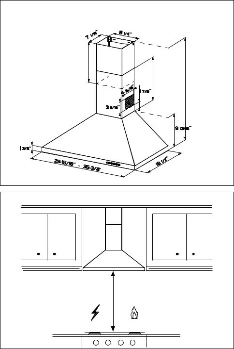
RANGEHOOD DIMENSIONS
|
0,1 |
|
|
|
0$; |
Min. 24" |
Min. 30" |
|
5 |
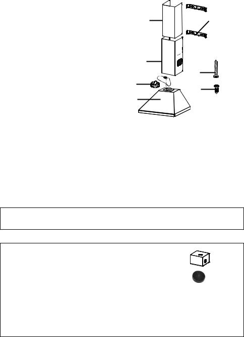
MAIN PARTS
|
|
Components |
Ref. |
Qty. |
Product Components |
1 |
1 |
Hood Body, complete with: Con- |
|
|
trols, Light, Filters, Blower. |
2 |
1 |
Telescopic Chimney comprising: |
2.1 |
1 |
Upper Section |
2.2 |
1 |
Lower Section |
10 |
1 |
Damper ø 5 7/8" |
Ref. |
Qty. |
Installation Components |
7.2.1 |
2 |
Upper Chimney Section Fixing |
|
|
Brackets |
12a |
8 |
Screws 3/16" x 1 3/4" |
12b |
4 |
Screws 1/8" x 3/8" |
|
Qty. |
Documentation |
|
1 |
Instruction Manual |
2.1  7.2.1
7.2.1
|
2.2 |
|
12a |
10 |
12b |
|
|
1 |
|
Parts needed
- 6" Round Metal ductwork .
Available Accessories
Direct Connect Wiring Box sku # WIREBOX
Activated Charcoal Filter sku # FILTER1
Long Lasting Activated Charcoal Filter sku# FILTER1LL
High Ceiling Chimney Kit - Upper and Lower Chimney Flue to replace the original flue's to fit up to 11' ceilings - sku# HIGHCLPL
Ductless Kit - Includes Ductless Diverter, Two Charcoal Filters - sku# DUCTCLPL
Wireless Remote Control-REMCTRL2
6
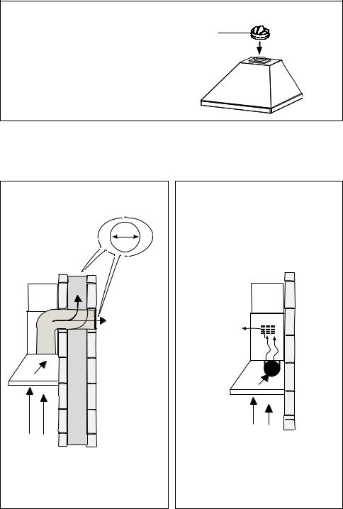
Only for Ducted Venting Installation
Install Damper that is included with the Hood before connecting to the ductwork.
|
Choose your ducting method |
|
Ducted Venting Installation |
Non Ducted - Recirculation |
|
Vertical |
6" |
|
|
|
|
Horizontal |
Requires |
|
purchase of |
||
|
||
|
Activated |
|
|
Charcoal |
|
|
Accessory |
7

Installation Instructions
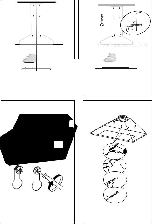
1
Draw a vertical line on the supporting wall as high as practical, at the center of the area in which the hood will be installed.
Draw a horizontal line at where the bottom edge of the hood will be located as indicated in the figure that is a minimum of 24" - 30" above cooking surface.
2
|
|
|
|
> ´ |
|
|
|
|
|
2.1 |
|
2.1 |
|
7.2.1 |
|
|
|
|
|
|
|
x6 |
||
|
|
|
|
|
5 1/2” |
5 1/2” |
|
|
|
|
|
|
||
|
|
|
|
|
|
|
|
” |
|
|
|
|
7 1/16 |
|
|
|
|
|
|
|
|
|
|
|
|
|
|
|
|
|
|
|
|
|
24” |
|
|
30” |
´ |
|
|
x6 |
||
|
|
|
|
Draw a horizontal line where indicated at the bottom edge of the vent hood at the desired height above the cooking surface.
Place a bracket 7.2.1 on the wall as shown about 1 1/8" from the ceiling or upper limit, aligning the centers(notch) with the vertical reference line and mark the wall at the centers of the holes in the bracket.
Place the second bracket 7.2.1 on the wall as shown, below the first bracket, at the height of the upper chimney section supplied and aligning the centers(notch) with the vertical line.
Mark the wall at the centers of the holes in the bracket and mark the point 1 and 2 for the Hood Body installation as show (7 1/16" from the horizontal line and 51/2" from the vertical line).
Drill ø 5/16" holes at all the centers points marked (point 1,2,3,4,5,6) as shown.
8
3 |
4 |
12aL = 2x
 3/16“
3/16“
!
Installationscrews provided must be secured with wall plugs (purchase separately).
5

 11I
11I
12aL
Hook the hood body onto the screws and screw completely.
Insert not completely the two screws 12a supplied in the hood body fixing holes as shown.
6
x2
Ø 5/16"8 mm
x2
x2
From inside the Hood body, mark the security hole, drill ø 5/16" where marked, insert 2 wall plugs 11 in the holes and fix with 2 screws.
9
7 |
Vertical or Horizontal |
Ducting Installation |
Install Roof or Wall Cap purchased separately. Connect the 6" metal ductwork to the Roof or Wall Cap and then attach ductwork.
8 Non-Ducted Recirculation Option
Only for the |
|
recirculation |
15 |
version, push fit the connection Ductless Diverter (purchased separately) onto the
hood body air outlet.
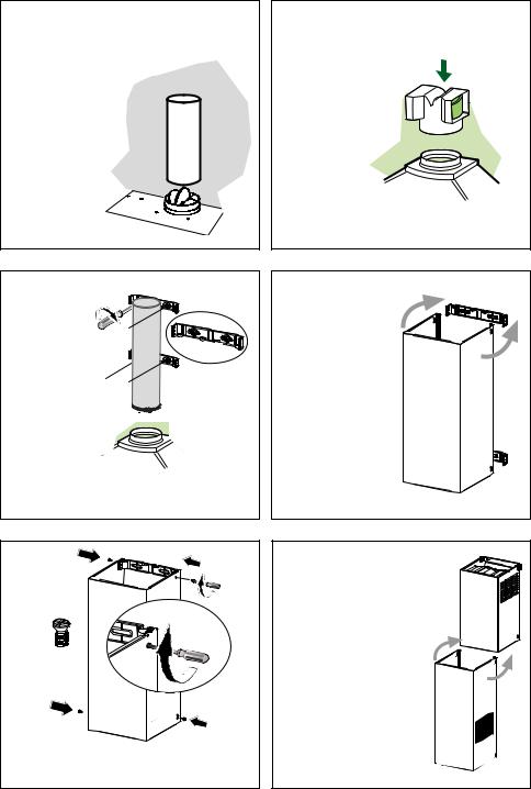
9 |
10 |
|
|
Slightly widen |
|
L = 4x |
the two sides |
|
12a |
of the upper |
2.1 |
Fix the bracket |
chimney and |
|
hook them |
|
|
7.2.1 using the |
|
|
behind the |
|
|
screws 12a |
|
|
brackets 7.2.1, |
|
|
supplied. |
|
|
making sure |
|
|
|
that they are |
|
|
well seated. |
|
11
12bN = 4x
Secure the sides to the brackets by using the 4 screws 12b.
12
2.1 
Slightly widen the two |
2.2 |
sides of the lower section |
and hook them between the upper section and the wall, making sure that they are properly housed.
10
13
ELECTRICAL INSTALLATION WITH CONNECTION
CABLE
GROUNDING INSTRUCTIONS This appliance must be grounded. In the event of an electrical short circuit, grounding reduces the risk of electric shock by providing an escape wire for the electric current. This appliance is equipped with a cord having a grounding wire with a grounding plug. The plug must be plugged into an outlet that is properly installed and grounded.
WARNING - Improper grounding can result in a risk of electric shock.
Consultaqualifiedelectricianifthegroundinginstructions are not completely understood, or if doubt exists as to whether the appliance is properly grounded.
Do not use an extension cord. If the power supply cord is too short, have a qualified electrician install an outlet near the appliance.
Max. 33 7/16”
ELECTRICAL INSTALLATION WITH
OPTIONALWIRING BOX
For Permanent wiring Installation-Use only with Listed rangehood Wiring Box kit
sku # WIREBOX, manufactured by Faber.
Direct Connect Wiring Box Accessory sku # WIREBOX (purchased separately)
14 For Non-Ducted Recirculation |
|
Attach each |
5 Option |
charcoal |
|
filter to the |
|
black grid on |
|
each side of |
|
the blower. |
|
Press the |
|
charcoal |
|
filter tightly |
W |
to the black grid on the blower side
and rotate the filter clockwise (towards the front of the hood) until it locks into place. Turn counterclockwise (towards the back of the hood) to remove.
Required Activated Charcoal Filter Accessory - sku # - FILTER1
Long Lasting Activated Charcoal Filter Accessory - sku # FILTER1LL (purchased separately)
15
Replace the grease filters removed previously.
11

USE AND CARE INFORMATION
For Best Results
Start the rangehood several minutes before cooking to develop proper airflow. Allow the rangehood to operate for several minutes after cooking is complete to clear all smoke and odors from the kitchen.
|
|
|
|
|
|
|
|
|
|
|
|
|
|
|
|
|
|
|
|
|
|
|
|
|
|
|
|
|
|
|
|
|
|
|
|
|
|
|
|
T1 |
T2 |
T3 |
T4 |
L |
|||||
T1. Fan off button:turn the blower Off. The fan can be operated by pressing any of the fan setting buttons.
Hold down this button for 2 seconds to activate Delay off function which will keep the fan on for 15 minutes and automatically shut off.
T2. Fan settings buttons: Low speed.
T3. Fan settings buttons: Medium speed.
T4. Fan settings buttons: High speed / Intensive speed.
Hold down the button for 2 seconds to activate the intensive speed, which is timed to run for 6 minutes. At the end of this time it will automatically return to the speed set before.Suitable to deal with maximum levels of cooking fumes.
L. Light button: On/Off switch for the lights.
NOTE: If your product has had a CFM adjustment, refer to the CFM adjustment manual for the information. Some motor speeds or functions may be reduced.
12
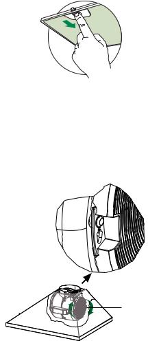
Cleaning metal grease filters
Themetalgreasefilterscanbecleanedinhotdetergent solution or washed in the dishwasher. They should be cleaned every 2 months, or more frequently if use is particularly heavy.
• Remove the filter, pushing the lever towards the back of the unit and at the same time pulling downward.
• Wash the filter without bending it, leave it to dry thoroughly before replacing (if the surface of the filter changes color over time, this will have absolutely no effect on its efficiency).
•Replace, taking care to ensure that the handle faces forward.
•Cleaning in dishwasher may dull the finish of the metal grease filter.
•No water can be present in filters before installing back in hood.
Replacing Activated Charcoal Filter |
5 |
TheActivated Charcoal Filters are not washable and cannot be regenerated, and should be replaced approximately every 4 months of operation, or more frequently with heavy usage.
•Remove the charcoal filter by rotating it clockwise ( backwards) until it unlocks from the motor housing and pull off sideways.
•To re-insert each charcoal filter, place up against the side of the blower and push it inward. Then
turn the charcoal filter clockwise (forward) until it |
W |
fits into place. |
|
• Caution: "When used in recirculation mode, to |
|
Reduce the Risk of Fire and Shock use only |
|
conversion kit Model FILTER 1 or FILTER1LL" |
|
LED LIGHTING UNIT
•LED lights must be replaced by Faber factory authorized service.
13

Wiring Diagram |
120V |
60Hz |
14 |
 Loading...