


SG - SG-D
Barrier Gate Operator
Installation Guide
Operator models contained in this manual conform to UL325 standard for use in Class I, II, III, and IV applications
USA & Canada (800) 421-1587 & (800) 392-0123
(760) 438-7000 - Toll Free FAX (800) 468-1340
www.linearcorp.com

Table of Contents
Pre-installation Information . . . . . . . . . . . . . . . . . . . . . . . . . . . . . . . . . .1
Before You Begin... . . . . . . . . . . . . . . . . . . . . . . . . . . . . . . . . . . . . . .1 Gate Operator Classifications . . . . . . . . . . . . . . . . . . . . . . . . . . . . . .1 Approved Obstruction Detection Devices . . . . . . . . . . . . . . . . . . . . .1
Safety Information and Warnings. . . . . . . . . . . . . . . . . . . . . . . . . . . . . .1 Regulatory Warnings . . . . . . . . . . . . . . . . . . . . . . . . . . . . . . . . . . . . .1
Wiring Specifications . . . . . . . . . . . . . . . . . . . . . . . . . . . . . . . . . . . . . . .2 AC Power Wiring . . . . . . . . . . . . . . . . . . . . . . . . . . . . . . . . . . . . . . . .2 DC Control and Accessory Wiring. . . . . . . . . . . . . . . . . . . . . . . . . . .2
Installation on Concrete Curb . . . . . . . . . . . . . . . . . . . . . . . . . . . . . . . .3
Barrier Gate Arm Installation . . . . . . . . . . . . . . . . . . . . . . . . . . . . . . . . .4 Attaching the Gate Arm . . . . . . . . . . . . . . . . . . . . . . . . . . . . . . . . . . .4
Operator Preparation . . . . . . . . . . . . . . . . . . . . . . . . . . . . . . . . . . . . . . .5 Gear Reducer Vent Plug . . . . . . . . . . . . . . . . . . . . . . . . . . . . . . . . . .5 Limit Cam Adjustments . . . . . . . . . . . . . . . . . . . . . . . . . . . . . . . . . . .5
Operator Setup . . . . . . . . . . . . . . . . . . . . . . . . . . . . . . . . . . . . . . . . . . . .6 Controller Access . . . . . . . . . . . . . . . . . . . . . . . . . . . . . . . . . . . . . . .6 AC Power Connection . . . . . . . . . . . . . . . . . . . . . . . . . . . . . . . . . . . .6
Earth Ground. . . . . . . . . . . . . . . . . . . . . . . . . . . . . . . . . . . . . . . . . . .6
Controller Features . . . . . . . . . . . . . . . . . . . . . . . . . . . . . . . . . . . . . . . . .7 Indicator Descriptions. . . . . . . . . . . . . . . . . . . . . . . . . . . . . . . . . . . . . . .8 Terminal Descriptions . . . . . . . . . . . . . . . . . . . . . . . . . . . . . . . . . . . . . . .9
Operator Accessory Connections . . . . . . . . . . . . . . . . . . . . . . . . . . . .10
Basic Controller Programming. . . . . . . . . . . . . . . . . . . . . . . . . . . . . . .11 Programming Overview . . . . . . . . . . . . . . . . . . . . . . . . . . . . . . . . . .11
Entering Programming Mode . . . . . . . . . . . . . . . . . . . . . . . . . . . . .11
Exiting Programming Mode . . . . . . . . . . . . . . . . . . . . . . . . . . . . . . .11 Programming Keystrokes . . . . . . . . . . . . . . . . . . . . . . . . . . . . . . . .11
Left or Right Hand Operation. . . . . . . . . . . . . . . . . . . . . . . . . . . . . .11
Dual Gate Enable . . . . . . . . . . . . . . . . . . . . . . . . . . . . . . . . . . . . . .11
Auto Close Timer . . . . . . . . . . . . . . . . . . . . . . . . . . . . . . . . . . . . . . .11
Run Alarm and Pre-start Alarm . . . . . . . . . . . . . . . . . . . . . . . . . . . .11 Maximum Close Direction Current Setting . . . . . . . . . . . . . . . . . . .12
Advanced Controller Programming . . . . . . . . . . . . . . . . . . . . . . . . . . .12 Entering Advanced Programming Mode . . . . . . . . . . . . . . . . . . . . .12
Maximum Run Time . . . . . . . . . . . . . . . . . . . . . . . . . . . . . . . . . . . .12
Single Button Input Setup . . . . . . . . . . . . . . . . . . . . . . . . . . . . . . . .13
Stagger Mode . . . . . . . . . . . . . . . . . . . . . . . . . . . . . . . . . . . . . . . . .13
Stagger Delay Time . . . . . . . . . . . . . . . . . . . . . . . . . . . . . . . . . . . . .13 Auxiliary Relay Mode. . . . . . . . . . . . . . . . . . . . . . . . . . . . . . . . . . . .13
Reverse Delay Time . . . . . . . . . . . . . . . . . . . . . . . . . . . . . . . . . . . .13
Low Power Mode . . . . . . . . . . . . . . . . . . . . . . . . . . . . . . . . . . . . . . .14
Power Failure Mode. . . . . . . . . . . . . . . . . . . . . . . . . . . . . . . . . . . . .14
Soft Start/Stop Duration . . . . . . . . . . . . . . . . . . . . . . . . . . . . . . . . .14 Reset Cycle Count . . . . . . . . . . . . . . . . . . . . . . . . . . . . . . . . . . . . .14
Maintenance Alert Trigger . . . . . . . . . . . . . . . . . . . . . . . . . . . . . . . .15
Open/Reset Input . . . . . . . . . . . . . . . . . . . . . . . . . . . . . . . . . . . . . .15
Anti-tailgate . . . . . . . . . . . . . . . . . . . . . . . . . . . . . . . . . . . . . . . . . . .15
Radio Enable. . . . . . . . . . . . . . . . . . . . . . . . . . . . . . . . . . . . . . . . . .15 Antenna Installation. . . . . . . . . . . . . . . . . . . . . . . . . . . . . . . . . . . . .15
Radio Transmitter Learn . . . . . . . . . . . . . . . . . . . . . . . . . . . . . . . . .16
Radio Transmitter Delete . . . . . . . . . . . . . . . . . . . . . . . . . . . . . . . . .16
MGT Obstacle Transmitter Learn . . . . . . . . . . . . . . . . . . . . . . . . . .16
MGT Obstacle Transmitter Delete . . . . . . . . . . . . . . . . . . . . . . . . . .16 Motor Type Selection . . . . . . . . . . . . . . . . . . . . . . . . . . . . . . . . . . . .16 Reset Controller to Factory Defaults . . . . . . . . . . . . . . . . . . . . . . . .16
Free Gate Loop Layout Illustration . . . . . . . . . . . . . . . . . . . . . . . . . . .17
Pay Gate Loop Layout Illustration . . . . . . . . . . . . . . . . . . . . . . . . . . . .18 Dual Gate Installations . . . . . . . . . . . . . . . . . . . . . . . . . . . . . . . . . . . . .19
Gate Operation. . . . . . . . . . . . . . . . . . . . . . . . . . . . . . . . . . . . . . . . . . . .19
Open Button . . . . . . . . . . . . . . . . . . . . . . . . . . . . . . . . . . . . . . . . . .19
Close Button . . . . . . . . . . . . . . . . . . . . . . . . . . . . . . . . . . . . . . . . . .19 Stop Button . . . . . . . . . . . . . . . . . . . . . . . . . . . . . . . . . . . . . . . . . . .19 Single Input . . . . . . . . . . . . . . . . . . . . . . . . . . . . . . . . . . . . . . . . . . .19 Fire Department Input . . . . . . . . . . . . . . . . . . . . . . . . . . . . . . . . . . .19
Open Input. . . . . . . . . . . . . . . . . . . . . . . . . . . . . . . . . . . . . . . . . . . .19
Open/Reset Input . . . . . . . . . . . . . . . . . . . . . . . . . . . . . . . . . . . . . .19 Close Obstruction Input. . . . . . . . . . . . . . . . . . . . . . . . . . . . . . . . . .19 Reverse Input . . . . . . . . . . . . . . . . . . . . . . . . . . . . . . . . . . . . . . . . .19 Open Loop. . . . . . . . . . . . . . . . . . . . . . . . . . . . . . . . . . . . . . . . . . . .19 Reverse Loop . . . . . . . . . . . . . . . . . . . . . . . . . . . . . . . . . . . . . . . . .19
Reset Loop . . . . . . . . . . . . . . . . . . . . . . . . . . . . . . . . . . . . . . . . . . .19
Operation Indications . . . . . . . . . . . . . . . . . . . . . . . . . . . . . . . . . . . . . .20
Power-up Display. . . . . . . . . . . . . . . . . . . . . . . . . . . . . . . . . . . . . . .20 Idle Condition . . . . . . . . . . . . . . . . . . . . . . . . . . . . . . . . . . . . . . . . .20 Last Gate Position/Condition . . . . . . . . . . . . . . . . . . . . . . . . . . . . . .20 Reverse Delay . . . . . . . . . . . . . . . . . . . . . . . . . . . . . . . . . . . . . . . . .20
Run Timer . . . . . . . . . . . . . . . . . . . . . . . . . . . . . . . . . . . . . . . . . . . .20
Error Indications . . . . . . . . . . . . . . . . . . . . . . . . . . . . . . . . . . . . . . . . . .20
Entrapment . . . . . . . . . . . . . . . . . . . . . . . . . . . . . . . . . . . . . . . . . . .20
COMM LINK Connection Failure . . . . . . . . . . . . . . . . . . . . . . . . . . .20 MGT Obstacle Transmitter Trouble . . . . . . . . . . . . . . . . . . . . . . . . .20 Maximum Run Time Exceeded . . . . . . . . . . . . . . . . . . . . . . . . . . . .20
Troubleshooting. . . . . . . . . . . . . . . . . . . . . . . . . . . . . . . . . . . . . . . . . . .21 Contacting Technical Support . . . . . . . . . . . . . . . . . . . . . . . . . . . . .21 Operator fails to start. . . . . . . . . . . . . . . . . . . . . . . . . . . . . . . . . . . .21
Motor operates, but gate does not move . . . . . . . . . . . . . . . . . . . . .21
Motor sounds like it is working harder than normal . . . . . . . . . . . . .21 Limit switch getting out of time . . . . . . . . . . . . . . . . . . . . . . . . . . . .21 Gate stopping part way open or closed . . . . . . . . . . . . . . . . . . . . .21 Gate staying open with automatic system . . . . . . . . . . . . . . . . . . . .21
How to Order Replacement Parts . . . . . . . . . . . . . . . . . . . . . . . . . .21
Model SG Exploded View . . . . . . . . . . . . . . . . . . . . . . . . . . . . . . . . . . .22 Model SG-D Exploded View . . . . . . . . . . . . . . . . . . . . . . . . . . . . . . . . .23 Model SG & SG-D Arm Parts List. . . . . . . . . . . . . . . . . . . . . . . . . . . . .24
Model SG and SG-D Maintenance . . . . . . . . . . . . . . . . . . . . . . . . . . . .25
Battery Maintenance . . . . . . . . . . . . . . . . . . . . . . . . . . . . . . . . . . . .25
Preventative Maintenance . . . . . . . . . . . . . . . . . . . . . . . . . . . . . . . . . .25
General . . . . . . . . . . . . . . . . . . . . . . . . . . . . . . . . . . . . . . . . . . . . . .25
Lubrication. . . . . . . . . . . . . . . . . . . . . . . . . . . . . . . . . . . . . . . . . . . .25 6-Month Preventative Maintenance . . . . . . . . . . . . . . . . . . . . . . . . .25
FCC Notice . . . . . . . . . . . . . . . . . . . . . . . . . . . . . . . . . . . . . . . . . . . . . . .25
Gate Operator Installation Checklist . . . . . . . . . . . . . . . . . . . . . . . . . .26
 WARNING
ONLY QUALIFIED TECHNICIANS
SHOULD WORK ON
LINEAR BARRIER GATE
OPERATORS
SG • SG-D Barrier Gate Operator Installation Guide |
P1277 Revision X2 8-11-2011 |

Pre-installation Information
Before You Begin...
Before unpacking, inspect the carton for exterior damage. If you find damage, advise the delivery carrier of a potential claim. Inspect your package carefully. You can check your accessory box parts with the enclosed packing slip for your convenience. Claims for shortages will be honored for only 30 days from the date of shipment.
Before installing the operator, read this manual completely to ensure all requirements for proper installation are present. Verify that the voltage to be used matches the voltage of the operator.
If you have any questions about the requirements for proper installation of this gate operator contact technical support at 800-421-1587
Gate Operator Classifications
All gate operators can be divided into one of four different classifications, depending on their design and usage. Install this gate operator only when the operator is appropriate for the construction and usage class as defined below:
• Class I Residential Vehicular Gate Operator
A vehicular gate operator intended for use in a home or for one to four single family dwellings with a common garage or parking area associated with these dwellings.
•Class II Commercial / General Access Vehicular Gate Operator
A vehicular gate operator intended for use in a commercial location or building such as a multi-family housing unit of fi ve or more single family units, hotel, retail store or other building servicing the general public.
•Class III Industrial / Limited Access Vehicular Gate Operator
A vehicular gate operator intended for use in an industrial location or building such as a factory or loading dock area or other location not intended to service the general public.
• Class IV Restricted Access Vehicular Gate Operator
A vehicular gate operator intended for use in a guarded industrial location or building such as an airport security area or other restricted access locations not servicing the general public, in which unauthorized access is prevented via supervision by security personnel.
Linear barrier gate operator models SG and SG-D meet the requirements for all four classifications.
Approved Obstruction Detection Devices
The following contact or non-contact obstruction detection devices have been approved for use with this swing gate operator as part of a UL325 compliant installation:
•Contact Edges
Miller Edge Models MGO20, MGR20, MGS20, ME120
•Photoeyes
MMTC Model IR-55 (165’ range - P/N 2520-441) MMTC Model E3K (28’ range - P/N 2520-031)
Safety Information and Warnings
THE FOLLOWING FORMATS ARE USED FOR SAFETY NOTES
IN THESE INSTRUCTIONS.
 CAUTION
This type of warning note is used to indicate the possibility of damage to the barrier arm or gate operator.
 WARNING
This type of warning note is used to indicate possible mechanical hazards that may cause serious injuries or death.
 WARNING
This type of warning note is used to indicate possible electrical shock hazards that may cause serious injuries or death.
Regulatory Warnings
Read the following before beginning to install this swing gate operator:
IMPORTANT INSTALLATION SAFETY INSTRUCTIONS
 WARNING
TO REDUCE THE RISK OF SEVERE INJURY OR DEATH TO PERSONS, REVIEW THESE INSTALLATION SAFETY STEPS BEFORE PROCEEDING
1.READ AND FOLLOW ALL INSTALLATION INSTRUCTIONS.
2.Read the blue “Safety Instructions” brochure enclosed with the packet of information. If any pages are missing or are unreadable, or you do not have the safety instructions, please call Linear at 1-800-333-1717 to request additional copies.
3.ALL ELECTRICAL CONNECTIONS TO THE POWER SUPPLY MUST BE MADE BY A LICENSED ELECTRICIAN AND MUST OBSERVE ALL NATIONAL AND LOCAL ELECTRICAL CODES.
4.A separate power-disconnect switch should be located near the operator so that primary power can be turned off when necessary.
5.Never connect a button station within reach of the barrier gate or on the side of the gate operator.
6.Do not adjust the operator controller’s current sensing feature too high. It should be adjusted high enough to keep the gate from falsely triggering the sensing, but no higher than necessary for the gate to operate. DO NOT DEFEAT THE PURPOSE OF THIS FUNCTION!
7.You must install all required safety equipment.
8.UL325 Compliance requires the use of contact edges or photoelectric controls on all automatic or remotely-controlled gate operators.
9.The operator is intended for installation only on gates used for vehicles. Pedestrians must be supplied with a separate access opening. The pedestrian access opening shall be designed to promote pedestrian usage. Locate the gate such that persons will not come into contact with the vehicular gate during the entire path of travel of the vehicular gate.
SG • SG-D Barrier Gate Operator Installation Guide |
- 1 - |
P1277 Revision X2 8-11-2011 |
Wiring Specifications
Refer to the following steps for details on power and accessory wiring for the operator.
 WARNING
ALL AC ELECTRICAL CONNECTIONS TO THE POWER SOURCE AND THE OPERATOR MUST BE MADE BY A LICENSED ELECTRICIAN AND MUST OBSERVE ALL NATIONAL AND LOCAL ELECTRICAL CODES.
USE COPPER WIRE ONLY!
AC Power Wiring
1.Find the listing on this page corresponding to the model, voltage and horsepower rating of your operator.
2.The distance shown in the table is measured in feet from the operator to the power source. DO NOT EXCEED THE MAXIMUM DISTANCE. These calculations have been based on standard 115 V and 230 V supplies with a 10% drop allowable. If your supply is under the standard rating, the runs listed may be longer than what your application will handle, and you should not run wire too near the maximum distance for the gauge of wire you are using.
3.When large-gauge wire is used, a separate junction box (not supplied) may be needed for the operator power connection.
4.Wire length calculations are based on the National Electrical Code, Article 430 and have been carefully determined based on motor inrush, brake solenoids, and operator requirements.
5.Connect power in accordance with local codes. The green ground wire must be properly connected.
6.Wire insulation must be suitable to the application.
7.Electrical outlets are supplied in all 115 VAC models for convenience with occasional use or low power consumption devices only. If you choose to run dedicated equipment from these devices, it will decrease the distance for maximum length and the charts will no longer be accurate.
DC Control and Accessory Wiring
1.All control devices are now 24 VDC, which can be run up to 2000 feet with 14 AWG wire.
2.Control wiring must be run in a separate conduit from power wiring. Running them together may cause interference and faulty signals in some accessories.
3.A three-wire shielded conductor cable is required to connect two operators together for dual operation. You must use Belden 8760 Twisted Pair Shielded Cable (or equivalent) only – P/N 2500-1982, per foot). See Page 19 for details of this connection. Note:The shield wire should be connected in both the operators.
MODEL SG POWER WIRING
VOLTS & HP |
MAXIMUM DISTANCE (FEET) |
WIRE GAUGE |
||
SINGLE |
DUAL |
|||
|
|
|||
|
222 |
111 |
12 |
|
115 VOLTS |
354 |
177 |
10 |
|
1/2-HP |
566 |
283 |
8 |
|
|
900 |
450 |
6 |
|
|
894 |
447 |
12 |
|
230 VOLTS |
1422 |
711 |
10 |
|
1/2-HP |
2264 |
1132 |
8 |
|
|
3600 |
1800 |
6 |
|
|
|
|
||
|
MODEL SG-D POWER WIRING |
|
||
VOLTS & HP |
MAXIMUM DISTANCE (FEET) |
WIRE GAUGE |
||
SINGLE |
DUAL |
|||
|
|
|||
|
222 |
111 |
12 |
|
115 VOLTS |
354 |
177 |
10 |
|
1/2-HP |
566 |
283 |
8 |
|
|
900 |
450 |
6 |
|
SG • SG-D Barrier Gate Operator Installation Guide |
- 2 - |
P1277 Revision X2 8-11-2011 |

Installation on Concrete Curb
The barrier gate operator bolts to a concrete island or curb.
1.Un-crate the gate. Avoid damaging the cabinet fi nish.
2.Leave the machine bolted to the bottom pallet until ready to install.
3.Open the cabinet door.
4.Remove the bolts holding the gate to its pallet and place the machine in position on the curb. Refer to your Equipment Layout (EL) drawing for proper positioning of your gate.
5.With a pencil, mark the location of the mounting holes on the concrete.
6.Set the gate aside. Drill all four mounting holes using a 3/4” diameter rotary hammer percussion drill bit. Insert lag screw anchors for 1/2” lag bolts. Place the gate back in position, and anchor it with 1/2” lag bolts and fl at washers. Lubricate the bolts before installation. Flat washers have been supplied to go between pavement and cabinet. Linear highly recommends using the corner mounting holes when mounting barrier gates.
7.Proceed with the rest of the installation process.
 WARNING
The gate must be installed in a location so that enough clearance is supplied between the gate and adjacent structures when opening and closing to reduce the risk of entrapment.
 WARNING
The operator is intended for installation only on gates used for vehicles. Pedestrians must be supplied with a separate access opening. The pedestrian access opening shall be designed to promote pedestrian usage. Locate the gate such that persons will not come into contact with the vehicular gate during the entire path of travel of the vehicular gate.
CABINET BASE |
|
1/2øX4" LAG BOLT |
|
AND FLAT WASHER |
|
SUPPLIED |
3/4ø HOLE |
FLAT WASHER |
IN CONCRETE |
LAG SCREW
 ANCHOR
Figure 1. Concrete Lag Anchor Detail
|
|
|
48" |
|
|
|
7-1/2" |
15" |
|
|
|
6-1/4" |
|
|
|
|
6-1/4" |
|
|
|
4" DIA. GUARD POSTS |
4-3/4" |
4-3/4" |
|
|
4 FT. TALL, BY OTHERS |
|
|
|
|
|
|
6-1/4" 7-1/2" |
|
|
|
|
15" |
48" |
|
|
|
ISLAND |
|
|
|
|
|
|
|
|
|
36" |
WIDTH |
|
.75 ø 8X |
|
6-1/4" |
(MINIMUM) |
|
OPEN SPACE FOR |
|
|
|
24" |
CONDUITS HERE |
|
|
|
|
|
|
|
|
|
14" MINIMUM |
|
SERVICE DOOR SIDE |
|
|
TO PROVIDE CLEARANCE FOR |
OF BARRIER GATE |
|
|
|
FLANGE AND COUNTERWEIGHTS |
(FACES AWAY FROM DRIVE) |
|
|
|
24" |
|
|
|
Figure 2. Barrier Gate Mounting Specifications
SG • SG-D Barrier Gate Operator Installation Guide |
- 3 - |
P1277 Revision X2 8-11-2011 |
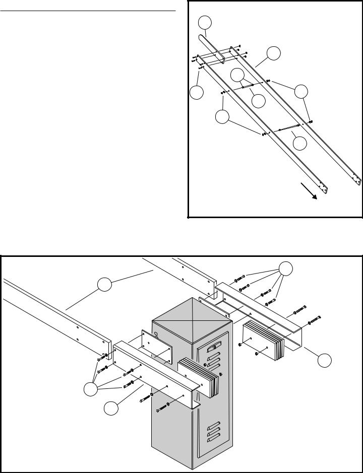
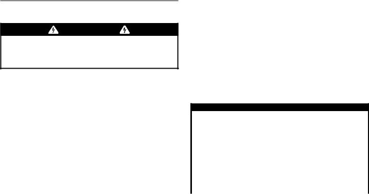
Barrier Gate Arm Installation
The barrier gate arm connects to the operator with the arm attachment channel and gate arm flange. Counterweights in the attachment channel balance the gate arm for smooth operation.
NOTE: Numbered items in these drawings are for instructional reference only. For actual part numbers, go to the parts lists in the back of this booklet.
Attaching the Gate Arm
1.Assemble the SG arm on the ground fi rst, making sure to leave all fasteners loose, including the spreader arms (Parts #4 & #7).
2.Make sure the barrier gate is in the full closed position.
3.With someone’s assistance, lift the arm up to a height even with the barrier gate fl ange. The far end should either be supported by something of equal height as the fl ange, or be held by someone throughout the next steps.
4.Assemble the wood arms (#10) between the attachment channels (#8) and the fl ange and bolt together. Tighten these bolts (#9) fi rmly.
5.Tighten all bolts (#3) where the three pieces of wood arm come together.
6.Tighten up the nuts (#6) on the spreader arms (#4 & #7) until the plates (#5) are tight against the wood.
7.The arm should have a curved, wishbone appearance once fi nished.
|
1 |
|
2 |
|
5 |
3 |
6 |
|
4 |
|
6 |
|
7 |
|
GATE |
|
OPERATOR |
|
END |
Figure 3. Wishbone Arm Assembly
9 |
10 |
8 |
9 |
8 |
|
Figure 4. Gate Arm Attachment |
SG • SG-D Barrier Gate Operator Installation Guide |
- 4 - |
P1277 Revision X2 8-11-2011

Operator Preparation
Gear Reducer Vent Plug
In order to keep gear oil from spilling out during shipping, gear reducers used in the SG and SG-D barrier gate operators have a sealed vent plug installed at the factory.
Leaving the vent plug installed, remove the vent plug’s breather pin to allow the gear box to vent (see Figure 5). The breather pin can be discarded.
Limit Cam Adjustments
The limit cams for all models of barrier gate operators have been pre-set at the factory for approximately 90 degrees of motion. If you need to adjust this further, see Figure 6 and follow the directions below.
1.For more downward travel, loosen the wingnut on the LSC-1 (down) limit cam and rotate the cam slightly in the “B” direction.
2.For less downward travel, loosen the wingnut on the LSC-1 (down) limit cam and rotate the cam slightly in the “A” direction.
3.For more upward travel, loosen the wingnut on the LSO-1 (up) limit cam and rotate the cam slightly in the “A” direction.
4.For less upward travel, loosen the wingnut on the LSO-1 (up) limit cam and rotate the cam slightly in the “B” direction.
NOTE: If the barrier gate operator has been custom configured by the factory for reverse arm operation (where the closed barrier arm sticks out from the service door side of the operator) the limit switches shown in Figure 6 will be reversed. The top limit switch will be the open limit, the bottom limit switch will be the close limit.
GEAR REDUCER
VENT PLUG
REMOVE THE
BREATHER PIN
Figure 5. Vent Plug Installation
CLOSE LIMIT
SWITCH LSC-1
OPEN
 LIMIT CAM
CLOSE 

 LIMIT CAM
DIRECTION DIRECTION "A" "B"
OPEN LIMIT 
SWITCH
LSO-1
Figure 6. Limit Cam Adjustment
SG • SG-D Barrier Gate Operator Installation Guide |
- 5 - |
P1277 Revision X2 8-11-2011 |

Operator Setup
Controller Access
The Controller in models SG and SG-D is located under the operator’s top cover.
To access the Controller, from inside the operator, flip the two cover release latches up to unlock the operator’s top cover. Remove the cover to expose the Controller.
The Controller is protected by a plastic dust cover. To remove the dust cover, loosen the cover’s wing-screw and lift the cover off.
AC Power Connection
All Linear gate operators are supplied with a power disconnect switch to turn on and off the power available to the operator (see Figure 8). Following wiring specifications on Page 2, incoming power should be brought into the operator and connected to the labeled pigtails from the disconnect box.
 WARNING
ALL AC ELECTRICAL CONNECTIONS TO THE POWER SOURCE AND THE OPERATOR MUST BE MADE BY A LICENSED ELECTRICIAN AND MUST OBSERVE ALL NATIONAL AND LOCAL ELECTRICAL CODES. POWER SUPPLY MUST BE OF CORRECT VOLTAGE AND PHASE.
NOTE: FOR SOLAR POWERED UNITS ONLY: The APeX Controller’s AC power disconnect switch does not turn off the Apex DC power when connected to solar panels. It will however, disconnect DC motor power. Unplug the solar panel input on the front of the Apex Controller prior to servicing the unit.
Proper thermal protection is supplied with the operator. The motor contains a thermal overload protector to guard from overheating the motor due to overload or high-frequency operation. To reset the motor after an overload, press the red button on the end of the motor after the motor has cooled down.
Earth Ground
Install a ground rod and connect it to the operator’s frame in every gate operator installation. A good earth ground is necessary to allow the Controller’s built-in surge and lightning protection circuitry to work effectively. The physical bolting of the operator to the mounting pad is not sufficient for a good earth ground.
NOTE: Do not splice the ground wire. Use a single piece of solid copper 12 AWG wire between the ground rod and the operator.
1.Install an 8-foot long copper ground rod next to the operator mounting pad within three feet of the operator.
2.Use a clamp to connect a solid copper 12 AWG ground wire to the ground rod.
3.Route the ground wire to the operator.
4.Connect the ground wire to the operator’s frame.
COVER
RELEASE 
LATCH
Figure 7. Cover Release Latch
115 VAC WIRING
GREEN - GROUND BLACK - HOT WHITE - NEUTRAL
CONNECT AC POWER
PIGTAIL LEADS TO
AC POWER SOURCE
SERVICE OUTLET
ON 115 VAC UNITS
ONLY
230 VAC WIRING
GREEN - GROUND BLACK - HOT WHITE - HOT
Figure 8. Power Disconnect Box Wiring
 WARNING
Always disconnect power from operator before servicing. Always keep clear of gate arm during operation.
SG • SG-D Barrier Gate Operator Installation Guide |
- 6 - |
P1277 Revision X2 8-11-2011 |

Controller Features
WHIP
ANTENNA
POWER
INDICATORS
DISPLAY
PROGRAMMING
BUTTONS
INPUT
POWER
TERMINALS
ACCESSORY
POWER
TERMINALS
RESET
BUTTON
TERMINALS
PRIMARY/
SECONDARY
COMM LINK
TERMINALS
SINGLE
INPUT
TERMINALS
FIRE DEPT
INPUT
TERMINALS
|
|
|
|
|
|
|
|
|
|
|
|
|
|
|
OPERATION AND |
|||||||||||
OPERATION |
|
|
|
|
|
|
|
PROGRAMMING |
||||||||||||||||||
BUTTONS |
|
|
|
|
|
|
|
|
INDICATORS |
|||||||||||||||||
|
|
|
|
|
|
|
|
|
|
|
|
|
|
|
|
|
|
|
|
|
|
|
|
|
|
|
OPEN INPUT
TERMINALS
3-BUTTON |
|
|
STATION |
OPEN/RESET |
SHADOW/RESET |
TERMINALS |
|
|
OPEN/RESET AND |
|
REVERSE LOOP |
LIMIT SWITCH |
AUXILIARY |
|
RELAY |
|||
CLOSE OBSTRUCTION |
REVERSE |
INPUT TERMINALS |
INPUT TERMINALS |
TERMINALS |
INPUT TERMINALS |
INPUT |
|
|
|
|
|
|
|
|
|
TERMINALS |
|
|
ALARM |
|
OPEN LOOP |
SHADOW/RESET LOOP |
||
|
INPUT TERMINALS |
|
INPUT TERMINALS |
OUTPUT |
|
|
|
|
TERMINALS |
ANTENNA
CONNECTOR
SOLAR
PANEL
TERMINALS
MOTOR
BOARD
COVER
BATTERY
TERMINALS
PLUG-IN
LOOP
DETECTOR
CONNECTORS
AC MOTOR
OUTPUT
TERMINALS
Figure 9. Controller Features
SG • SG-D Barrier Gate Operator Installation Guide |
- 7 - |
P1277 Revision X2 8-11-2011 |
 Loading...