


E124

|
|
|
|
INDEX |
|
|
|
|
|
|
|
1 LAY-OUT OF ELECTRICAL BOX........................................................................................ |
2 |
||||
2 |
|
WARNINGS ................................................................................................................... |
4 |
||
3 LAYOUT AND COMPONENTS OF E124 ........................................................................... |
4 |
||||
|
3.1 INPUTS DEFAULT SETTING ............................................................................................ |
4 |
|||
|
3.2 DESCRIPTION OF COMPONENTS ............................................................................... |
5 |
|||
4 |
|
TECHNICAL SPECIFICATIONS ......................................................................................... |
5 |
||
5 TERMINAL BOARDS, CONNECTORS, INPUTS AND SIGNALS ............................................ |
6 |
||||
|
5.1 |
TERMINAL BOARD J3 – CONNECTION TO BUS-2EASY ACCESSORIES ........................ |
6 |
||
|
5.2 |
TERMINAL BOARD J4 – SIGNALS INPUTS .................................................................... |
6 |
||
|
5.3 |
TERMINAL BOARDS J5, J8 – OUT1 AND OUT2 ............................................................ |
6 |
||
|
5.4 |
TERMINAL BOARD J6 – OPENING AND CLOSING TRAVEL LIMIT DEVICE...................... |
7 |
||
|
5.5 |
TERMINAL BOARDS J7 - ENCODERS .......................................................................... |
7 |
||
|
5.6 |
TERMINAL BOARD J9 – FLASHING LAMP .................................................................... |
7 |
||
|
5.7 |
TERMINAL BOARD J10 – ELECTRIC LOCK................................................................... |
7 |
||
|
5.8 |
TERMINAL BOARD J11, J12 - MOTORS ...................................................................... |
7 |
||
|
5.9 |
CONNECTOR J1 - PRIMARY POWER FEED FROM 230/115 V MAINS .......................... |
7 |
||
|
5.10 CONNECTOR J2 - SECONDARY POWER FEED ............................................................ |
8 |
|||
|
5.11 Connector J13 – XF MODULE rapid connection ...................................................... |
8 |
|||
|
5.12 CONNECTOR J14FOR RAPID CONNECTION OF MINIDEC, DECODER AND RP ......... |
8 |
|||
|
5.13 Connector M1A – Rapid connection MODULE X-COM ............................................ |
8 |
|||
6 |
|
ELECTRICAL CONNECTIONS .......................................................................................... |
9 |
||
|
6.1 |
TRADITIONAL PHOTOCELLS........................................................................................ |
9 |
||
|
6.2 |
PHOTOCELLS BUS-2EASY ........................................................................................... |
11 |
||
|
|
6.2.1 ADDRESSING THE BUS-2EASY PHOTOCELLS ........................................................ |
11 |
||
|
|
6.2.2 MEMORY STORAGE OF BUS-2EASY ACCESSORIES ............................................... |
12 |
||
|
|
6.2.3 ADDRESSING THE BUS-2EASY ENCODERS ............................................................ |
12 |
||
7. |
|
PROGRAMMING............................................................................................................ |
13 |
||
|
7.1. |
1ST LEVEL PROGRAMMING ........................................................................................ |
13 |
||
|
7.2. |
2nd LEVEL PROGRAMMING ....................................................................................... |
16 |
||
|
7.3. PROGRAMMING FROM PC (3rd LEVEL)....................................................................... |
22 |
|||
8 SAVING THE RADIO CODE ............................................................................................. |
22 |
||||
|
8.1 |
SAVING DS RADIO CONTROLS .................................................................................. |
22 |
||
|
8.2 |
SAVING SLH RADIO CONTROLS ................................................................................. |
22 |
||
|
8.3 |
MEMORY STORAGE OF THE LC/RC RADIO CONTROLS (FOR SOME MARKETS ONLY) .. |
23 |
||
|
|
8.3.1 REMOTE SAVING OF LC/RC RADIO CONTROLS.................................................... |
23 |
||
|
8.4 |
RADIO CONTROLS DELETION PROCEDURE ............................................................... |
23 |
||
9 |
|
CONNECTION TO EMERGENCY BATTERIES (OPTIONAL) ................................................. |
23 |
||
10 |
|
START-UP |
....................................................................................................................... |
24 |
|
|
10.1 LEDS CHECK ............................................................................................................. |
24 |
|||
|
10.2 TIME LEARNING .............................................................................................- SETUP |
25 |
|||
11 |
|
AUTOMATED SYSTEM TEST ............................................................................................. |
25 |
||
12 ALARM AND ........................................................................................ERROR SIGNALS |
25 |
||||
|
12.1 ALARMS.................................................................................................................... |
25 |
|||
|
12.2 ERRORS .................................................................................................................... |
25 |
|||
13 |
|
FUNCTION LOGICS ........................................................................................................ |
26 |
||
|
|
|
|
CE DECLARATION OF CONFORMITY |
|
Manufacturer: |
FAAC S.p.A. |
|
|||
Address: |
Via Calari, 10 - 40069 Zola Predosa BOLOGNA - ITALY |
|
|||
Declares that: |
The E124 control unit |
|
|||
• ·conforms to the essential safety requirements of the following EEC directives
2006/95/EC Low Voltage Directive
2004/108/EC Electromagnetic Compatibility Directive
Additional note:
This product underwent tests in a typical uniform configuration (all products manufactured by FAAC S.p.A.).
Bologna, 01 - 01 - 2010
The Managing Director
A.Marcellan
WARNINGS
•Important! For the safety of people, it is important that all the instructions be carefully observed.
•Incorrect installation or incorrect use of the product could cause serious harm to people.
•Carefully read the instructions before beginning to install the product and keep them for future reference.
• The symbol |
indicates notes that are important for the safety of persons and for the good condition of the automated system. |
• The symbol |
draws your attention to the notes on the characteristics and operation of the product. |
ENGLISH
1

E124 CONTROL UNIT
1 LAY-OUT OF ELECTRICAL BOX
 The box contains the E124 control unit and the devices to power it. It must therefore be handled with care during all installation stages, to avoid damaging its components.
The dimensions of the box are shown in Fig. 1:
ENGLISH 306
64 130
225
Dimensions in mm
Fig. 1
Fig. 2 shows the four 5 mm diam. holes for securing the box (ref. ) to the wall, the three fittings for installing the cable grippers M16/ M20/M25 (ref. ) and the two lid hinges (ref. ).
If it is necessary to remove and re-position the E124 control board, make sure that the spacers (ref. ) are fitted in the supports.
Fig. 2
2

The lid hinges can be moved upward to allow opening the box housing (Fig. 3): they can also be removed and re-positioned in order to enable the lid to open to the right or left.
Connect the power cable to the switching feeder as shown in Fig.5, making sure that there is an adequate thermal breaker upstream.
Neutral
Fig. 3
Line
Earth
ENGLISH
When you have secured the box in the selected position, cover the securing holes (Fig. 2 ref. ) and the screws with the supplied plugs as shown in Fig. 4.
Fig. 5
Then plug the connector of the transformer to connector J1 on the board as indicated in fig.6.
Fig. 4
Fig. 6
3

2 WARNINGS
Attention: Before attempting any work on the control unit (connections, maintenance), always turn off power.
-Install, upstream of the system, a differential thermal breaker with adequate tripping threshold,
-Connect the earth cable to the relevant terminal (see fig.5).
-Always separate power cables from control and safety cables (push-button, receiver, photocells, etc.). To avoid any electrical disturbance, use separate sheaths or a screened cable (with the screen earthed).
ENGLISH
3 LAYOUT AND COMPONENTS OF E124
M1A |
J14 |
J2 |
|
|
|
DL14 |
|
|
DL15 |
|
|
|
|
SW1 |
J1 |
|
M1A |
|
|
|
|
|
|
|
|
|
|
J13 |
J15 |
|
|
|
DL16 |
|
LCD |
SW2 |
|
||
|
|
|
|
||
|
|
|
|
|
|
|
|
|
|
|
DL17 |
|
DL19 |
|
|
|
|
|
SW7 |
|
|
SW3 |
|
|
DL20 |
|
|
|
DL18 |
|
|
|
|
|
|
|
SW4 |
SW5 |
|
SW6 |
|
DL12 |
DL13 |
DL1 |
DL2 |
DL3 |
DL4 |
DL5 |
DL6 |
DL7 |
DL8 |
DL9 |
DL10 DL11 |
|
|
|
|
|
|
|
J5 |
|
|
|
|
J3 |
|
J4 |
|
|
|
|
+ |
|
|
|
J7 |
|
|
|
|
|
|
J6 |
|
|
|
J8 |
J9 |
J10 |
J11 |
J12 |
+
Fig. 7
3.1 INPUTS DEFAULT SETTING
Terminal-board J4
IN1 |
OPEN A |
N.O. contact |
IN2 |
OPEN B |
N.O. contact |
|
|
|
IN3 |
STOP |
N.C. contact |
|
|
|
IN4 |
FSW OP |
N.C. contact |
|
|
|
IN5 |
FSW CL |
N.C. contact |
|
|
|
Connector J13 – XF Module (OMNIDEC)
Channel 1 |
OPEN A |
|
|
Channel 2 |
OPEN B |
|
|
Connector J14 - Radio |
|
|
|
Channel 1 RP |
OPEN A |
|
|
Channel 2 RP2 |
OPEN B |
|
|
4

3.2 DESCRIPTION OF COMPONENTS
LCD |
SIGNALS AND PROGRAMMING DISPLAY |
|
|
SW1 |
“R1” PROGRAMMING PUSH-BUTTON |
|
|
SW2 |
“R2” PROGRAMMING PUSH-BUTTON |
|
|
SW3 |
“SETUP” PUSH-BUTTON |
|
|
SW4 |
“+” PROGRAMMING PUSH-BUTTON |
|
|
SW5 |
“-” PROGRAMMING PUSH-BUTTON |
|
|
SW6 |
“F” PROGRAMMING PUSH-BUTTON |
|
|
SW7 |
“RESET SW” SOFTWARE RESET PUSH-BUTTON |
|
|
DL1 |
INPUT STATUS CONTROL LED “IN1” |
|
|
DL2 |
INPUT STATUS CONTROL LED “IN2” |
|
|
DL3 |
INPUT STATUS CONTROL LED “IN3” |
|
|
DL4 |
INPUT STATUS CONTROL LED “IN4” |
|
|
DL5 |
INPUT STATUS CONTROL LED “IN5” |
|
|
DL6 |
INPUT STATUS CONTROL LED “FCA1” |
|
|
DL7 |
INPUT STATUS CONTROL LED “FCC1” |
|
|
DL8 |
INPUT STATUS CONTROL LED “FCA2” |
|
|
DL9 |
INPUT STATUS CONTROL LED “FCC2” |
|
|
DL10 |
INPUT STATUS CONTROL LED “ENC1” |
|
|
DL11 |
INPUT STATUS CONTROL LED “ENC2” |
|
|
DL12 |
SIGNALLING LED FOR DEVICE BUS-2EASY ACTIVE |
|
|
DL13 |
SIGNALLING LED FOR BUS 2-EASY DIAGNOSTICS |
|
|
DL14 |
LED SIGNALLING PRIMARY POWER ON |
|
|
DL15 |
LED SIGNALLING SECONDARY POWER ON (See chap.9) |
|
|
4 |
TECHNICAL SPECIFICATIONS |
||
|
|
||
Primary power feed |
with switching power feed |
||
from mains |
230/115 V~ - 50/60 Hz |
||
Secondary power |
24 Vdc - 16 A max. |
||
feed |
|
(min. 20 Vdc. - max. 28 Vdc.) |
|
Power absorbed |
stand-by = 4W |
||
from mains |
max. ~ 400 W |
||
Max. load |
7 A |
||
for motor |
|||
|
|||
Power feed |
24 Vdc |
||
for accessories |
|||
|
|||
Accessories |
24Vdc max. 500 mA |
||
max. current |
BUS-2EASY max. 500 mA |
||
Battery charge |
180 mA |
||
current |
|
||
|
|
||
Operating ambient |
(-20 - +55) °C |
||
temperature |
|||
|
|||
Protective fuses |
All self resetting |
||
for unit |
|
||
|
|
||
Protective fuses for |
2.5 A |
||
power pack |
|||
|
|||
|
|
|
|
|
|
|
|
|
|
|
|
DL16 |
SIGNALLING LED FOR “SW1” PUSH-BUTTON (R1 PUSH-BUTTON) |
|
|
||
|
|
|
|
|
|
DL17 |
SIGNALLING LED FOR “SW2” PUSH-BUTTON (R2 PUSH-BUTTON) |
|
|
||
|
|
|
|
|
|
DL18 |
SIGNALLING LED FOR “SW3” PUSH-BUTTON (SETUP PUSH-BUTTON) |
|
|
||
|
|
|
|
|
|
DL19 |
PRESSURE SIGNALLING LED “RESET SW” PUSH-BUTTON |
|
|
||
|
|
|
|
|
|
DL20 |
ALARM SIGNALLING LED “ALARM” |
|
|
||
|
|
|
|
|
|
J1 |
POWER FEEDER SWITCHING CONNECTOR (PRIMARY POWER) |
|
|
||
|
|
|
|
|
|
J2 |
SECONDARY POWER SELECTOR |
|
|
||
|
|
||||
|
|
|
|
|
|
J3 |
CONNECTOR FOR CONNECTION TO BUS-2EASY DEVICES |
|
|
||
|
|
|
|
|
|
J4 |
CONNECTOR FOR TERMINAL BOARD INPUTS (see chap.4.1) |
|
ENGLISH |
||
|
|
|
|
|
|
J5 |
CONNECTOR FOR OUT2 OUTPUT (see 2nd level prog.) |
|
|||
|
|
||||
|
|
|
|
|
|
J6 |
TRAVEL LIMITS CONNECTOR |
|
|
||
|
|
|
|
|
|
J7 |
CONNECTOR FOR LEAF 1 AND LEAF 2 ENCODER INPUTS |
|
|
||
|
|
|
|
|
|
J8 |
CONNECTOR FOR OUT1 OUTPUT (see 2nd level prog.) |
|
|
||
|
|
|
|
|
|
J9 |
FLASHING LAMP OUTPUT CONNECTOR |
|
|
||
|
|
|
|
|
|
J10 |
CONNECTOR FOR ELECTRICAL LOCK OUTPUT |
|
|
||
|
|
|
|
|
|
J11 |
LEAF 1 MOTOR CONNECTOR |
|
|
||
|
|
|
|
|
|
J12 |
LEAF 2 MOTOR CONNECTOR |
|
|
||
|
|
|
|
|
|
J13 |
CONNECTOR FOR RECEIVER MODULE XF433/XF868 |
|
|
||
|
|
|
|
|
|
J14 |
CONNECTOR: DECODER / MINIDEC / RP RECEIVER |
|
|
||
|
|
|
|
|
|
J15 |
USB CONNECTOR FOR PROGRAMMING FROM PC |
|
|
||
|
|
|
|
|
|
M1A |
MODULE X-COM CONNECTOR |
|
|
||
|
|
|
|
|
|
|
Flashing LED ALARM indicates alarm in progress |
|
|
||
|
(a situation which does not prejudice gate |
|
|
||
|
operation) |
|
|
|
|
|
LED ALARM on steady light indicates error in |
|
|
||
|
progress (a situation which blocks operation |
|
|
||
|
until cause of error is eliminated) |
|
|
||
|
|
|
|
||
Function logics |
Semiautomatic, Automatic, |
|
|
||
|
|
“step-by-step” Semiautomatic, Automatic |
|
|
|
|
|
with reverse during pause, Automatic |
|
|
|
|
|
step-by-step, Safety devices automatic, |
|
|
|
|
|
Safety devices step-by-step automatic, |
|
|
|
|
|
“b” Semiautomatic, mixed logic “bC”, |
|
|
|
|
|
Dead-man, Automatic with timer function |
|
|
|
Work time |
Programmable (from 0 to 9 min 50 sec) |
|
|
||
Pause time |
Programmable (from 0 to 9 min 50 sec) |
|
|
||
|
|
|
|
||
Motor power |
Programmable on 50 levels |
|
|
||
|
|
|
|
||
Motor speed |
Programmable on 10 levels |
|
|
||
|
|
|
|
||
Connector inputs |
Switching feeder, Battery, |
|
|
||
|
|
Decoder/Minidec/RP, X-COM, module |
|
|
|
|
|
XF433/868, USB |
|
|
|
Terminal board inputs |
BUS-2EASY, Inputs from IN1 to IN5 (see |
|
|
||
|
|
par. 5), Travel limit device, Encoder. |
|
|
|
|
|
|
|
||
Terminal board outputs |
Flashing lamp, Motors, Electrical lock, |
|
|
||
|
|
OUT1, OUT2 (programmable), power feed |
|
|
|
|
|
to accessories |
|
|
|
Programming |
1st and 2° lev. with 3 keys (+, -, F) and LCD |
|
|
||
|
|
display. |
|
|
|
|
|
3rd lev. with P.C. connected via USB or with |
|
|
|
|
|
X-COM module. |
|
|
|
5
5 TERMINAL BOARDS, CONNECTORS, INPUTS AND SIGNALS
5.1TERMINAL BOARD J3 – CONNECTION TO BUS-2EASY ACCESSORIES
Terminal for connection of BUS-2EASY accessories. see par. 6.2
5.2TERMINAL BOARD J4 – SIGNALS INPUTS
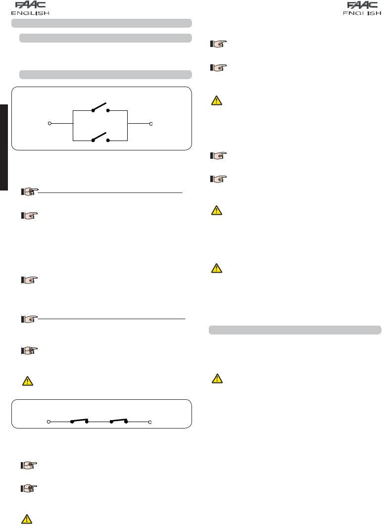
Connection of 2 N.O. contacts in parallel
ENGLISH |
this refers to any pulse generator (e.g.: push-button) which, |
|
Fig. 8 |
|
IN1 - OPEN A - “Opening” Command (N.O. - terminal 1): |
|
by closing a contact, commands TOTAL OPENING. |
|
Toinstallseveraltotalopeningpulsegenerators, |
|
connect the N.O. contacts in parallel |

 Other more detailed programming possibilities
 are feasible by programming with a PC (see dedicated instructions).
IN2 - OPEN B - Partial Opening” command (N.O. - terminal 3): this refers to any pulse generator (e.g.: push-button) which, by closing a contact, commands PARTIAL OPENING.

 For double leaf or single leaf systems, OPEN
 B commands an opening of leaf 1 (motor 1) corresponding to 50% of total opening (can be modified by PC up to 100%)

 To install several partial opening pulse
 generators, connect the N.O. contacts in parallel
 Other more detailed programming possibilities
  are feasible by programming with a PC (see dedicated instructions).
If you select one of the following logics (b, bC, C) input IN2 automatically becomes CLOSE
(N.O).
Connection of 2 NC contacts in series
Fig. 9
IN3 - STOP contact command (N.C. - terminal 4): this refers to any device (e.g.: push-button ) which, by opening a contact, can stop the motion of the automated system.
 To install several STOP devices, connect the N.C.
  contacts in series.
 Other more detailed programming possibilities
  are feasible by programming with a PC (see dedicated instructions).
Ifstopsafetydevicesarenotconnected,jumper connect the STOP and GND terminals.
IN4 - Opening safety-devices contact (N.C. - terminal 5): see paragraph 6.1.

 To install several opening safety devices, connect
 the N.C. contacts in series.

 Other more detailed programming possibilities
 are feasible by programming with a PC (see dedicated instructions).
If opening safety devices are not connected, jumper connect terminals IN4 and GND, if the FAIL-SAFE safety device is not active, otherwise jumper connect IN4 and –OUT1.
IN5 - Closing safety-devices contact (N.C. -. terminal 7): see paragraph 6.1.

 To install several closing safety devices, connect
 the N.C. contacts in series

 Other more detailed programming possibilities
 are feasible by programming with a PC (see dedicated instructions).
If closing safety devices are not connected, jumper connect terminals IN5 and GND, if the FAIL-SAFE safety device is not active, otherwise jumper connect IN5 and –OUT1.
GND - (terminals 2-6): Negative for powering accessories +24 - (terminal 8): Positive to power feed accessories
The max. load of the accessories is 500mA, subdivided among terminal boards J4 and J7. To calculate maximum absorption, refer to the instructions for individual accessories.
5.3 TERMINAL BOARDS J5, J8 – OUT1 AND OUT2
The two outputs can be set in one of the functions described in 2nd level programming (see par.7.2.). The default value is:
OUT1 = ALWAYS ACTIVE OUT2 = INDICATOR LIGHT.
Maximum load applicable on every output: 24 Vdc with 100 mA.
6

5.4 TERMINAL BOARD J6 – OPENING AND CLOSING TRAVEL LIMIT DEVICE
Terminal board for connection of the opening (FCA1 and FCA2) and closing (FCC1 and FCC2) travel limit device.
The travel limit contacts FCC1, FCA1, FCC2 and FCA2 are all NC contacts. See 2nd level programming for the various configurations
applicable to the travel limit inputs.
If they are not used, do not jumper connect the contacts of the limit switches FCC1, FCA1, FCC2, FCA2
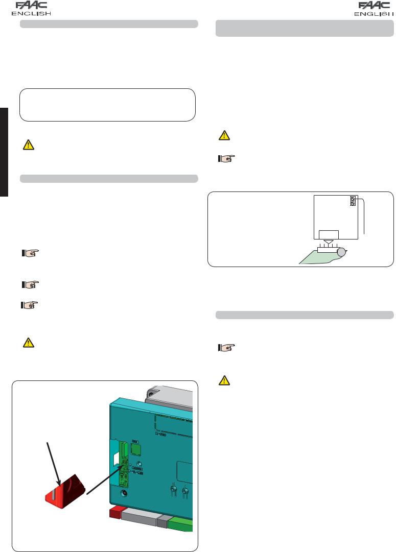
5.5 TERMINAL BOARDS J7 - ENCODERS
Encoders with an open collector signal referred to earth (e.g. Gatecoder) can be connected to detect the leaf’s angular position. For connections, see fig. 10.

 The configuration indicated in the drawing is
 the maximum one. Only 1 Gatecoder can be used. In this case, the unused inputs do not have to be jumper connected to earth

 The default obstacle detection and stop point
times are 2 and 4 seconds respectively.
WHITE |
RED |
|
|
|
BLACK |
WHITE |
RED |
|
BLACK
Fig. 10
5.6 TERMINAL BOARD J9 – FLASHING LAMP
Output for 24Vdc flashing lamp
Maximum applicable load: 24 Vdc - 15 W
5.7 TERMINAL BOARD J10 – ELECTRIC LOCK
Output for 12V ac or 24V dc electric lock
5.8 TERMINAL BOARD J11, J12 - MOTORS
J11 (MOT1): Connection of motor connected to leaf 1, i.e. the leaf which opens first during an opening operation.
J12 (MOT2): Connection of the motor connected to leaf 2, i.e. the leaf which opens second.
If only one motor is connected, it must be connected to terminal J11 (MOT1).
If, during the first movement of the SETUP procedure, the leaves open instead of closing, themotorconnectioncablesmustbechanged over.
5.9 CONNECTOR J1 - PRIMARY POWER FEED FROM |
ENGLISH |
|
|
230/115 V MAINS |
|
J1: Select the correct power feed, by turning the power switching
selector to its correct position (Default 230 Vac.)
115 Vac |
230 Vac |
Fig. 11
To ensure correct operation, the switching feeder must be connected to the earth conductor in the system. Install an adequate differential thermal breaker upstream of the system.
7
5.10 CONNECTOR J2 - SECONDARY POWER FEED
J2: In the absence of a primary feed from the mains, the control unit can be fed by a secondary low voltage (24Vdc) power feed. Power can be supplied by a pack of batteries, recharged by a battery charger integrated in the board, or by a stabilised power feeder. In both cases, the power supply must have the following characteristics:
Voltage: (24 ± 4) Vdc
Current: 16 A max.
ENGLISH
If you use an external stabilised feeder, you must disable the “battery charger” function via the PC (see dedicated instructions).
5.11 CONNECTOR J13 – XF MODULE RAPID CONNECTION
The control unit has an integrated 2-channel decoding system (DS, SLH, LC/RC) named OMNIDEC. This system makes it possible to save – through an extra receiver module – F433 or XF868 (Fig.12 ref. ) – radio commands of the same frequency, but of a different type (DS, SLH, LC/RC). It is possible to save both total opening (OPEN A) and partial opening (OPEN B) of the automated system, up to a maximum of 256 channels.

 Other more detailed programming possibilities
 are feasible by programming with a PC (see dedicated instructions).

 To save the radio commands, refer to
Chap.8.

 The function of the 2nd channel (by default OPEN B)
can be changed if associated with the activation of a programmable output.
(see 2ND LEVEL progr. o1 and o2 parameter 14-15)
Insert and remove the boards only after cutting power.
Fig. 12
5.12 CONNECTOR J14FOR RAPID CONNECTION OF MINIDEC, DECODER AND RP
It is used for rapid connection of Minidecs, Decoders and RP/RP2 Receivers.
If you are using an RP2 twin-channel receiver, you will be able to directly command two different radio channels, OPEN A and OPEN B of the automated system from a twin-channel radio control.
If using a single-channel Minidec, Decoder or RP, you can command only one radio channel, OPEN A.
Fit the accessory with the components side directed toward the board interior.
Insert and remove the boards ONLY after cutting power.

 Other more detailed programming possibilities
 are feasible by programming with a PC (see dedicated instructions).
An example of a radio accessory connection
|
J14 |
|
|
6 |
Fig. 13 |
E124 |
|
|
|
|
5.13 CONNECTOR M1A – RAPID CONNECTION MODULE X-COM
An X-COM module can be connected to this connector, used for radio communication between board and PC.

 Other more detailed programming possibilities
 are feasible by programming with a PC (see dedicated instructions.
Insert and remove the module only after cutting power.
8
 Loading...