


E721
< (1) |
BUS 2EASY |
|
|
|
|
|
|
< (2) |
|
|
|
|
|
|
|
< OPEN A |
|
|
|
|
|
|
|
< GND |
|
|
|
|
|
|
|
< OPEN B / CLOSE / SAFE |
|
|
RADIO XF |
|
|||
< STOP / SAFE |
|
|
|
|
|
||
|
|
|
|
|
|
||
< FSW OP |
|
|
|
|
|
|
|
< GND |
|
|
|
|
|
|
|
< FSW CL |
|
|
|
|
|
|
|
< +24 |
|
|
|
|
|
|
|
< (PE |
< |
TRANS |
< |
TRANS |
<BATTERY |
<M |
|
MAIN |
-L) |
PRIM |
F |
|
F |
|
OR |
|
|
|
SEC |
|
OT |
||
-N |
|
|
|
|
|
|
|
|
|
|
|
|
|
|
|
|
F |
|
|
|
|
|
ERRORPOWER |
- |
|||
|
FCC |
FCA |
|
|
+ |
||||
|
|
RADIO1RADIO2 |
|
|
SETUP |
|
|||
|
|
|
|
|
|
|
|
|
|
|
|
|
RELEASE |
|
BATTERY |
|
|
USB |
|
|
|
|
|
|
|
|
|
||
|
AMP |
|
LOCK |
|
LOCK |
|
OCK |
OUT |
|
|
|
|
|
- + |
|
||||
L |
< |
< |
L |
|
|||||
< |
|
|
< |
|
|
|
|||
|
CONTENTS |
|
1 WARNINGS..................................................................................................................................................... |
|
2 |
2 LAYOUT AND COMPONENTS........................................................................................................................... |
2 |
|
2.1 COMPONENT DESCRIPTION ...................................................................................................................................... |
3 |
|
2.2 DESCRIPTION OF TERMINAL BLOCK J13.................................................................................................................... |
3 |
|
3 TECHNICAL SPECIFICATIONS .......................................................................................................................... |
3 |
|
4 ELECTRIC CONNECTIONS............................................................................................................................... |
4 |
|
4.1 BUS-2EASY PHOTOCELLS............................................................................................................................................ |
5 |
|
4.1.1 ADDRESSING BUS-2EASY PHOTOCELLS .......................................................................................................................... |
5 |
|
4.1.2 STORING BUS-2EASY ACCESSORIES ............................................................................................................................. |
5 |
|
4.2 TRADITIONAL PHOTOCELLS ....................................................................................................................................... |
5 |
|
4.3 SAFE INPUT CONNECTIONS......................................................................................................................... |
7 |
|
5 PROGRAMMING ............................................................................................................................................ |
8 |
|
5.1 1st LEVEL PROGRAMMING ........................................................................................................................................ |
8 |
|
5.2 2nd LEVEL PROGRAMMING ...................................................................................................................................... |
10 |
|
6 STORING RADIO CODE ................................................................................................................................ |
12 |
|
6.1 STORING DS RADIOCONTROLS ............................................................................................................................... |
12 |
|
6.2 STORING SLH RADIOCONTROLS ............................................................................................................................. |
13 |
|
6.3 STORING LC/RC RADIOCONTROLS (ONLY FOR SOME MARKETS) ............................................................................ |
13 |
|
6.3.1 STORING LC/RC RADIOCONTROLS REMOTELY ........................................................................................................... |
13 |
|
6.4 RADIOCONTROLS DELETION PROCEDURE .............................................................................................................. |
13 |
|
7 OPERATIONAL START-UP ............................................................................................................................... |
14 |
|
7.1 CHECKING THE LEDS ................................................................................................................................................ |
14 |
|
7.2 BATTERY OPERATION ............................................................................................................................... |
14 |
|
7.3 POSITIONING LIMIT SWITCHES .................................................................................................................................... |
|
|
7.4 MASTER / SLAVE CONFIGURATIONS......................................................................................................................... |
16 |
|
7.4.1 MASTER / SLAVE WIRING ............................................................................................................................................ |
16 |
|
7.4.2 MASTER/SLAVE SETUP PROCEDURE............................................................................................................................. |
16 |
|
7.5 SETUP ....................................................................................................................................................................... |
|
17 |
8 TESTING THE AUTOMATED SYSTEM ........................................................................................................... |
17 |
|
9 ALARM AND ERROR SIGNALS .................................................................................................................. |
17 |
|
9.1 ALARMS ................................................................................................................................................................... |
|
17 |
9.2 ERRORS .................................................................................................................................................................. |
|
17 |
10 FUNCTION LOGICS .................................................................................................................................... |
18 |
|
|
CE DECLARATION OF CONFORMITY |
|
Manufacturer: FAAC S.p.A. |
|
|
Address: |
Via Calari, 10 - 40069 Zola Predosa BOLOGNA - ITALY |
|
Declares that: Control board E721 |
|
|
|
• conforms to the essential safety requirements of the following EEC directives |
|
|
2006/95/EC Low Voltage Directive |
|
|
2004/108/EC Electromagnetic Compatibility Directive |
|
|
Additional note: |
|
|
This product has undergone testing in a typical |
|
|
standard configuration (all products built by FAAC S.p.A. ) |
|
Bologna, 01-12-2010
The Managing Director
A. Marcellan
WARNINGS
•Attention! To ensure the safety of people, it is important that you read all the following instructions.
•Incorrect installation or incorrect use of the product could cause serious harm to people.
•Carefully read the instructions before beginning to install the product and keep for future reference.
•The symbol highlights notes that are important for personal safety and the protection of the automated system.
•The symbol 
 calls your attention to notes on product specifications or operation.
ENGLISH
1
ENGLISH
E721
1 WARNINGS
Before attempting any work on the control board (connections, maintenance), always turn off power.
Install, upstream of the system, a differential thermal breaker with adequate tripping threshold.
Connect the earth lead to the appropriate terminal. |
 Always separate power cables from control and safety cables
  (push-button, receiver, photocells, etc.). To avoid any electric noise, use separate sheaths or a shielded cable (with earthed shield).
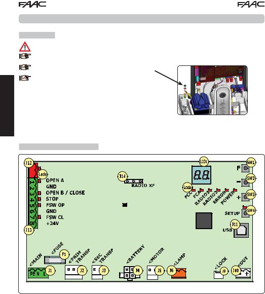
2 LAYOUT AND COMPONENTS
/ SAFE |
/ SAFE |
SENSOR |
LIMIT SWITCH |
Fig. 1
2
2.1 COMPONENT DESCRIPTION
LCD |
SIGNALLING AND PROGRAMMING DISPLAY |
|
|
|
|
SW1 |
PROGRAMMING PUSH-BUTTON "F". |
|
|
|
|
SW2 |
PROGRAMMING PUSH-BUTTON "-". |
|
|
|
|
SW3 |
PROGRAMMING PUSH-BUTTON "+". |
|
|
|
|
SW4 |
“SETUP” PUSH-BUTTON |
|
|
|
|
LEDs |
INPUTS STATUS CONTROL LED |
|
|
|
|
J1 |
MAIN POWER SUPPLY CONNECTOR |
|
|
|
|
J2 |
TRANSFORMER PRIMARY WINDING CONNECTOR |
|
|
|
|
J3 |
TRANSFORMER SECONDARY WINDING CONNECTOR |
|
|
|
|
J4 |
EMERGENCY BATTERY CONNECTOR (ACCESSORY) |
|
|
|
|
J5 |
MOTOR CONNECTOR |
|
|
|
|
J6 |
FLASHING LAMP CONNECTOR (24 V= - 15W) |
|
|
|
|
J9 |
MOTOR LOCK AND MOTOR RELEASE |
|
CONTACT CONNECTOR |
||
|
||
J10 |
OUT OUTPUT CONNECTOR |
|
|
|
|
J11 |
USB CONNECTOR FOR PC CONNECTION |
|
|
|
|
J12 |
BUS-2EASY DEVICE CONNECTION CONNECTOR |
|
|
|
|
J13 |
INPUT CONNECTOR IN CONNECTOR BLOCK |
|
|
|
|
J14 |
RADIO RECEIVER MODULE CONNECTOR FOR OMNIDEC |
|
|
|
|
LCD1 |
SIGNALLING AND PROGRAMMING DISPLAY |
|
|
|
|
F1 |
PROTECTION FUSE |
|
|
|
2.2 DESCRIPTION OF TERMINAL BLOCK J13
INPUT |
No |
DESCRIPTION |
|
|
|
1 |
OPEN A |
Device with N.O. contact |
|
|
that causes total opening |
|
|
of the gate |
2-6 |
GND |
Accessory power |
|
|
supply negative |
3(1) |
OPEN B |
Device with N.O. contact |
|
(DEFAULT) |
that causes partial opening |
|
|
of the gate |
|
CLOSE |
Device with N.O. contact |
|
|
that closes the gate |
|
SAFE |
Device with N.C. contact |
|
|
that causes the immediate |
|
|
and complete reversal of |
|
|
the gate |
4(1) |
STOP |
Device with N.C. contact |
|
(DEFAULT) |
that halts the gate |
|
SAFE |
Device with N.C. contact |
|
|
that causes the immediate |
|
|
and complete reversal of |
|
|
the gate |
5 |
FSW OP |
Device with N.C contact |
|
|
that reverses the motion |
|
|
during gate opening |
7 |
FSW CL |
Device with N.C contact |
|
|
that reverses the motion |
|
|
during gate closing |
8 |
+24 V= |
Accessory power supply |
|
|
positive |
3 TECHNICAL SPECIFICATIONS
Power supply |
230 V~ 50 Hz |
|
|
|
|
|
|
Power consumption |
10 W |
|
|
from mains stand-by |
|
|
|
Motor max. load |
10A |
|
|
|
|
|
|
Accessory |
24 V= |
|
|
power supply |
|
|
|
Accessory |
24 V= max. 500 mA |
|
|
max. current |
BUS-2EASY max. 500 mA |
|
|
Environmental |
(-20 - +55) °C |
|
|
|
|
||
temperature |
|
|
|
Flashing lamp |
24 V= - 15 W |
|
ENGLISH |
load |
|
|
|
Output load |
24 V= - 100 mA (2) |
|
|
|
|
||
|
|
|
|
Protection |
F1 = T1A - 250V~ |
|
|
fuses |
|
|
|
Function |
Semiautomatic, Semiautomatic “step“, |
|
|
logics |
Automatic, Automatic “step”, Auto- |
|
|
|
matic with timer function, Automatic |
|
|
|
Safety devices, Automatic Safety devices |
|
|
|
“step“, Automatic with reverse on pause, |
|
|
|
|
|
|
|
Semiautomatic “b”, Mixed logic “bC”, |
|
|
|
Dead-man. |
|
|
Work time |
Programmable (from 0 to 10 min.) |
|
|
|
|
|
|
Pause time |
Programmable (from 0 to 10 min.) |
|
|
OPEN A / OPEN B |
|
|
|
Motor power |
Adjustable over 50 levels |
|
|
|
|
|
|
Opening-closing |
Adjustable over 10 levels |
|
|
motor speed |
|
|
|
Connector Inputs/ |
Power supply, Battery, Motor, Module |
|
|
Outputs |
XF433/868, Motor lock electric release bat- |
|
|
|
teries, Motor Lock, USB |
|
|
Inputs/Outputs in |
BUS-2EASY, OPEN A, OPEN B/CLOSE/SAFE, |
|
|
terminal block |
STOP/SAFE, GND, Opening and closing |
|
|
|
photocells, +24 V=, Mains power supply, |
|
|
|
Flasher, Electric release motor lock, OUT |
|
|
Programming |
1st and 2nd level with 3 keys (+, -, F) and |
|
|
|
display. |
|
|

 (1) The uses of inputs 3 and 4 can be set by
 configuring the corresponding parameters at programming level 2 (parameters Ob and SP). For the exact description on how to operate the automated system with the chosen logics, please refer to the tables featured at the end of this manual (Par. 10 - OPERATION LOGICS. As for the wiring required using these SAFE configured inputs, please refer to the diagrams shown in Fig.12 and Fig. 13

 (2) The output load must be considered
 as already included in the max. current available for the accessories
3
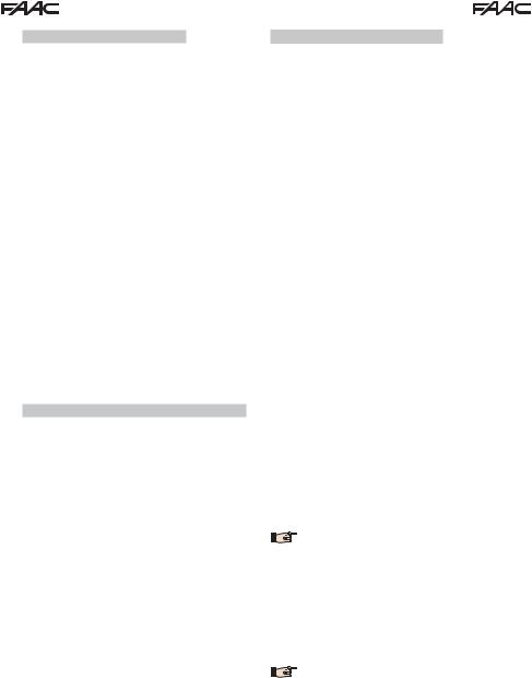
4 ELECTRIC CONNECTIONS
The wiring shown in Fig. 2 refers to the inputs of the board with DEFAULT configuration. |
ENGLISH
/ SAFE |
/ SAFE |
To connect the photocells and safety devices, consult paragraph 4.2
|
|
|
|
|
|
|
|
|
|
|
|
|
|
|
|
|
|
|
|
|
|
|
|
|
|
|
|
|
|
|
|
|
|
|
|
|
|
|
|
|
|
|
|
|
|
|
|
|
|
|
|
|
|
|
|
|
|
|
|
|
|
|
|
|
|
|
|
|
|
|
|
|
|
|
|
|
|
|
MOTOR RELEASE |
|
||||
|
|
|
|
|
|
|
|
|
|
|
|
|||||
|
|
|
|
|
|
|
|
|
|
|
|
|||||
|
|
|
|
|
|
|
|
|
|
|
CONTACT |
|
||||
|
|
|
|
|
|
|
|
|
|
|
(Locks the motor when |
|
||||
|
= |
the motor release han- |
|
|||||||||||||
|
|
|
|
|
|
|
|
|
|
|
dle is operated) |
|
||||
A: Photocells that operate during CLOSING
B: Photocells that operate during OPENING
C: Photocells that operate during OPENING and CLOSING

 =
=
Fig. 2
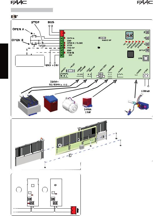
Fig. 4
RX |
|
|
|
|
TX |
|
|
|
|
DL1 |
|
|
|
|
|
DL2 |
|||
|
|
|
|
|
|
||||
|
ON |
|
DS1 |
|
ON |
|
DS1 |
||
1 |
2 |
3 |
4 |
|
1 |
2 |
3 |
4 |
|
DL2 |
|
|
|
|
|
|
|
|
|
|
|
BUS |
BUS |
|
BUS |
BUS |
|||
RX - TX
DL1 = Alignment
DL2 = BUS - 2EASY/Power supply status DS1 = Dipswitches for programming
Fig. 3
Before connecting the photocells, it is advisable to select the type of operation on the basis of the area of movement that they need to protect:
Safety devices during closing: operate only during the automated system closing movement and are therefore suitable for protecting the closing area from the risk of impact.
Safety devices during opening: operate only during the automated system opening movement and are therefore suitable for protecting the opening area from the risk of impact.
Safety devices during opening/closing: operate during both the automated system opening and closing movements and are therefore suitable for protecting the entire movement area from the risk of impact.
4

4.1 BUS-2EASY PHOTOCELLS
This board is equipped with a BUS-2EASY circuit that can be used to easily connect a high number of auxiliary BUS2EASY devices to the safety device (e.g. up to 16 pairs of photocells), appropriately programmed, using only two cables without polarity.
Before connecting the photocells, it is advisable to select the type of operation (Fig. 3) on the basis of the area of movement the cells must protect and to position the dip switches on both the transmitter and receiver (see Fig. 4) as in Tab. 1.
4.1.1 ADDRESSING BUS-2EASY PHOTOCELLS
 It is important to give both the transmitter
  and the receiver the same address.
Ensure that there are not two or more pho- |
tocell pairs with the same address. |
If no BUS-2EASY accessory is used, leave the |
BUS-2EASY connector (J12 - fig. 1) free. |
Tab. 1 - Addressing BUS-2EASY photocells
Dip1 |
Dip2 |
Dip3 |
Dip4 |
Re. |
Type |
|
|
|
|
|
|
|
|
OFF |
OFF |
OFF |
OFF |
|
|
|
OFF |
OFF |
OFF |
ON |
|
|
|
OFF |
OFF |
ON |
OFF |
B |
OPENING |
|
OFF |
OFF |
ON |
ON |
Max. 6 pairs |
||
|
||||||
|
|
|||||
OFF |
ON |
ON |
OFF |
|
|
|
OFF |
ON |
ON |
ON |
|
|
|
ON |
OFF |
OFF |
OFF |
|
|
|
ON |
OFF |
OFF |
ON |
|
|
|
ON |
OFF |
ON |
OFF |
|
|
|
ON |
OFF |
ON |
ON |
A |
CLOSING |
|
Max. 7 pairs |
||||||
ON |
ON |
OFF |
OFF |
|
||
|
|
|||||
ON |
ON |
OFF |
ON |
|
|
|
ON |
ON |
ON |
OFF |
|
|
|
OFF |
ON |
OFF |
OFF |
|
OPENING and |
|
|
|
|
|
C |
CLOSING |
|
OFF |
ON |
OFF |
ON |
|||
|
Max. 2 pairs |
|||||
ON |
ON |
ON |
ON |
/ |
OPEN PULSE |
4.1.2 STORING BUS-2EASY ACCESSORIES
At any time it is possible to add BUS-2EASY photocells and accessories to the system, simply by following the procedure below:
1.Install and programme the accessories with the required address (see par. 4.1.1).
2.Cut off power to the board.
3.Connect both cables of the BUS-2EASY accessories to the red terminal block J12 (polarity irrelevant).
4.Power the board.
5.Quickly press the SETUP push-button (SW4) once to register the accessories. Check the operation of the installed BUS-2EASY devices.
6.The board has stored the BUS-2EASY accessories.
Follow the instructions in the following table to check that the BUS-2EASY connection status is efficient.

 The same procedure must be performed on a
MASTER unit also when acquiring a SLAVE unit connected to the BUS2EASY with POLARISED connection
Tab. 2 - Description of BUS-2EASY LED
Fixed ON |
Normal activity (LED on even without pho- |
|
tocells). No registered photocell engaged. |
||
|
||
|
|
|
Slow |
At least one registered photocell engaged |
|
flasher |
or not aligned. |
Off (flash
every |
BUS-2EASY line short-circuited. |
|
2.5 secs) |
|
|
|
|
|
|
- BUS-2EASY line disabled (does not supply |
|
Off |
power) |
|
- Battery operation |
||
|
||
|
- Unit programmed as a SLAVE |
4.2 TRADITIONAL PHOTOCELLS
Connection of 1 pair of closing photocells with FAIL-SAFE safety device activated
Set in second level of programming
o1 = 01
OUT 


Other safety devices
OUT


 OUT
OUT
Connection of 1 pair of closing photocells
with FAIL-SAFE and STOP safety device deactivated
Other safety devices
Fig. 5

 If the FAIL-SAFE safety device is not
used, connect the power supply of the transmitters to terminals 6 and 8 of J13.

 If the FAIL-SAFE safety device is used, connect
the power supply of the transmitters to OUT after setting it as appropriate (see 2nd level programming and Fig. 5).

 If the FAIL-SAFE safety device is used, even the
 unused safety inputs must be connected via a shunt lead to the negative of OUT (see Fig. 5).
ENGLISH
5

ENGLISH
Connection of a pair of opening photocells
Other safety devices
Fig. 6
Connection of a pair of closing photocells and a pair of opening photocells
Fig. 7
Connection of two pairs of closing photocells
Fig. 8
Connection of a pair of closing photocells and a pair of opening/closing photocells
Fig. 9
Connection of a pair of closing photocells, a pair of opening photocells and a pair of opening/closing photocells
Fig. 10
Connection of no safety and stop device
Fig. 11
6
 Loading...