


J200 HA

CE DECLARATION OF CONFORMITY FOR MACHINES
(DIRECTIVE 2006/42/EC)
Manufacturer: FAAC S.p.A.
Address: Via Calari, 10 - 40069 Zola Predosa BOLOGNA - ITALY
Declares that: the operator mod. J200 HA
is built to be integrated into a machine or to be assembled with other machinery to create a machine under the provisions of Directive 2006/42/EC;
conforms to the essential safety requirements of the following EEC directives:
2006/95/EC |
Low Voltage Directive |
2004/108/EC |
Electromagnetic Compatibility Directive |
and also declares that it is prohibited to put into service the machinery until the machine in which it will be integrated or of which it will become a component has been identified and declared as conforming to the conditions of Directive 2006/42/EEC and subsequent amendments.
Bologna, 01st September 2012
The Managing Director
A. Marcellan
CE DECLARATION OF CONFORMITY FOR MACHINES
ENGLISH
Manufacturer: FAAC S.p.A.
Address: Via Calari, 10 - 40069 Zola Predosa BOLOGNA - ITALY
Declares that: the control unit 624BLD
• conforms to the essential safety requirements of the following EEC directives:
2006/95/EC |
Low Voltage Directive |
2004/108/EC |
Electromagnetic Compatibility Directive |
Additional note:
This product underwent tests in a typical homogenous configuration (all products manufactured by FAAC S.p.A.).
Bologna, 01st September 2012
The Managing Director
A. Marcellan
1

ENGLISH
WARNINGS FOR THE INSTALLER
GENERAL SAFETY OBLIGATIONS
1.ATTENTION! To ensure the safety of people, it is important that you read all the following instructions. Incorrect installation or incorrect use of the product could cause serious harm to people.
2.Carefully read the instructions before beginning to install the product.
3.Donot leavepackingmaterials(plastic,polystyrene,etc.) within reachof children
as such materials are potential sources of danger.
4.Store these instructions for future reference.
5.This product was designed and built strictly for the use indicated in this documentation. Any other use, not expressly indicated here, could compromise the good condition/operation of the product and/or be a source of danger.
6.FAAC declines all liability caused by improper use or use other than that for which the automated system was intended.
7.Do not install the equipment in an explosive atmosphere: the presence of inflammable gas or fumes is a serious danger to safety.
8.For non-EU countries, to obtain an adequate level of safety, the Standards mentioned above must be observed, in addition to national legal regulations.
9.FAAC is not responsible for failure to observe GoodTechnique in the construction of the closing elements to be motorised, or for any deformation that may occur during use.
10.Installation must be performed in compliance with current Standards.
11.Before attempting any job on the system, cut out electrical power.
12.The mains power supply of the automated system must be fitted with an all-pole switch with contact opening distance of 3 mm or greater. Use of a 6A thermal breaker with all-pole circuit break is recommended.
13.Make sure that a differential switch with threshold of 0.03 A is fitted upstream of the system.
14.Make sure that the earthing system is perfectly constructed and connect metal parts of the closure to it.
15.The automated system is supplied with an intrinsic anti-crushing safety device consisting of a torque control. Nevertheless, its tripping threshold must be checked as specified in the Standards indicated at point 10.
16.The safety devices (EN 12978 standard) protect any danger areas against mechanical movement Risks, such as crushing, dragging, and shearing.
17.Use of at least one indicator-light (i.e. flashing lamp incorporated in the bollard head) is recommended for every system, as well as a warning sign adequately secured to the frame structure, in addition to the devices mentioned at point “16”.
18.FAAC declines all liability as concerns safety and efficient operation of the automated system, if system components not produced by FAAC are used.
19.For maintenance, strictly use original parts by FAAC.
20.Do not in any way modify the components of the automated system.
21.The installer shall supply the user with the necessary information for the manual operation of the system in the event of emergency
22.Do not allow children or adults to stay near the product while it is operating.
23.Keepremotecontrolsorotherpulsegeneratorsawayfromchildren,topreventthe automated system from being activated involuntarily.
24.Transit on the bollard is permitted only when the device is completely down.
25.The user must not attempt any kind of repair or direct action whatever and contact qualified personnel only.
26.Anything not expressly specified in these instructions is not permitted.
|
INDEX |
|
1 |
GENERAL NOTES ......................................................................................................................................... |
3 |
2 |
DESCRIPTION AND TECHNICAL SPECIFICATIONS................................................................................... |
3 |
3 |
DIMENSIONS.................................................................................................................................................. |
4 |
4 |
FACILITIES ..................................................................................................................................................... |
4 |
5 |
ELECTRIC WIRING ........................................................................................................................................ |
6 |
6 |
MANUAL OPERATION................................................................................................................................... |
9 |
7 |
AUTOMATIC OPERATION ............................................................................................................................. |
9 |
8 |
MAINTENANCE.............................................................................................................................................. |
9 |
9 |
ELECTRICAL CONNECTIONS .................................................................................................................... |
10 |
10 |
PRE-SETTING SELECTION.......................................................................................................................... |
11 |
11 |
POSITIONING THE LOOPS .......................................................................................................................... |
11 |
12 |
CONNECTING MORE BOLLARDS ............................................................................................................. |
12 |
|
12.1 CONNECTION OF UP TO 4 BOLLARDS ON A SINGLE BOARD.................................................................... |
12 |
|
12.2 CONNECTION OF UP TO 8 BOLLARDS ON TWO 624BLD MASTER – SLAVE CONNECTION ................. |
12 |
|
12.3 WIRING OF UP TO 4 BOLLARDS ON A SINGLE BOARD .............................................................................. |
13 |
|
12.4 WIRING OF UP TO 8 BOLLARDS ON TWO 624BLD IN MASTER – SLAVE CONNECTION ....................... |
14 |
13 |
TROUBLESHOOTING.................................................................................................................................. |
15 |
14 |
CLEANING / UNMOUNTING PROCEDURE................................................................................................ |
15 |
2

J200 HA BOLLARD
Please read with the utmost care this manual supplied with the product, since it contains important indications about safety, installation, use and maintenance.
1 GENERAL NOTES
J200HA is an automatic hydraulic traffic bollard. The cylinder is moved by an hydraulic unit located inside the cylinder. The hydraulic release occurs by direct action on the hydraulic unit. As an alternative, if the optional solenoid valve is present, the release occurs automatically in the event of a power cut.
2 DESCRIPTION AND TECHNICAL SPECIFICATIONS


1. Hydraulic unit
2. Junction box
3. Cable routing hole
4. Magnetic contact, down (NC polarity)
5. Crown
6.LED flashing lamp
7.Reflective stripe
8.Oil filler plug
9.Piston
10.Cylinder
11.Magnetic contact, up (NC polarity)
12.Cable routing chain
13.Upper plate (bollard)
14.Upper plate (Hydraulic unit)
15.4 stop points, up
16.stoppers, down
17.Water drainage holes

|
|


Fig. 1
ENGLISH
3
ENGLISH
Tab. A - Technical Specifications
MODEL |
|
J200 |
|
|
|
Power supply |
230 V~ 50 Hz |
|
|
|
|
Max. absorbed power (W) |
220 |
|
|
|
|
Max. force (N) |
1800 |
|
|
|
|
Max. pump delivery (lpm) |
3 |
|
|
|
|
Minimum lifting time (sec) |
7 |
|
|
|
|
Minimum lowering time (sec) |
7 |
|
|
|
|
Use temperature (°C) |
-15 +55 |
|
|
|
|
Weight (Kg) |
100 |
|
|
|
|
Oil quantity (l) |
2,6 |
|
|
|
|
Protection class |
IP56 |
|
|
|
|
Overall dimensions |
See Fig.2 |
|
|
|
|
Capacitor (3) |
16μF - 400V |
|
|
|
|
Use frequency |
Semi-Intensive use |
|
|
|
|
R.O.T. at 55°C |
(min) |
40 |
|
|
|
R.O.T. at 23°C |
(min) |
100 |
|
|
|
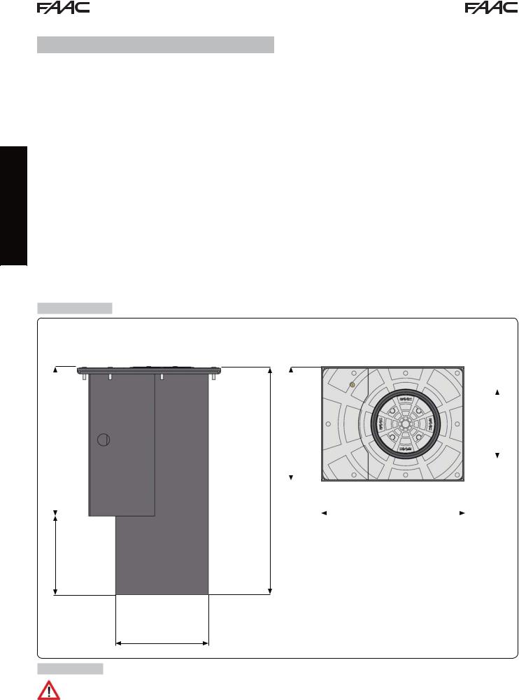
3 DIMENSIONS
Dimensions in mm
|
|
400 |
|
|
|
|
|
|
|
|
515 |
|
200 |
|
|||||||
|
|
|||||||||
|
|
790 |
|
|
|
|
|
|
|
|
|
|
|
|
|
|
|
|
|
||
|
|
|
|
|
|
|
|
|
||
|
|
|
|
|
|
|
|
|
||
|
|
|
|
|
500 |
|
|
|
|
|
|
|
|
|
|
|
|
|
|
|
|
275
322
Fig. 2
4 FACILITIES
Make sure that the place where the bollard is to be installed is not a cavity; if this is the case, partially protect the bollard with a drainage channel equipped with covering grid.
 Dig up to a depth of about 1.1 m
4

The dig can be square and have a side of about 1 m (fig. 3). Otherwise it can be carried out using an earth drill with a diameter of 50 cm up to the depth mentioned above and widened in the last 30 cm giving a square shape of 1 m per side
1000
Dimensions in mm
1100
 40lt 30’
1000
800 300
500
Fig. 3
Make sure that the ground is able to absorb water: pour about 40 l water and evaluate if draining requires less than 30 minutes. If this is not the case, discharge rain water by means of a pipeline with a diameter of 60mm connected to the drainage system or, as an alternative, connected to a pit, equipped with a drainage system (such as a motor pump), having a depth greater than the pit for the collection and drainage of rain water
ENGLISH
Introduce gravel (grain diameter: approx. 20 mm.) to obtain a thickness of about 30 cm, taking care to compact it well to avoid future settlements
|
|
|
|
1000 |
|
|
|
1000 |
|
|
|
Fig. 4 |
|||||||||
|
|
|
|
|
|
|
|
|
|
|
|
|
|
|
|
|
|
|
|
|
|
|
|
|
|
|
|
|
|
|
|
|
|
|
|
|
|
|
|
|
|
|
|
|
|
|
|
|
|
|
|
|
|
300 |
|
|
|
|
|
|
|
|
|
|
|
|
|
|
|
|
|
|
|
|
|
|
|
|
|
|
|
|
|
|
|
||
1100 |
|
800 |
|
|
|
|
1100 |
|
500 |
|
|
|
|
|
|
|
|
|
|
|
|
|
|
|
|
|
|
|
|
|
|
|
|
|
|
|
|
|
|||||
|
|
|
|
|
|
|
|
|
|
|
|
|
|
|
|
|
|||||
|
|
300 |
|
|
|
|
|
|
|
300 |
|
|
|
|
|
|
|
|
|
|
|
|
|
|
|
|
|
|
|
|
|
|
|
|
|
|
|
|
|
|
|
||
|
|
|
|
|
|
|
|
|
|
|
|
|
|
|
|
|
|
|
|
||
|
|
|
|
|
|
|
|
|
|
|
|
|
|
|
|
|
|
|
|
||
|
|
|
|
|
|
|
|
|
|
|
|
|
|
|
|
|
|
|
|
|
|
|
|
|
|
|
|
|
|
|
|
|
|
|
|
|
|
|
|
|
|
|
|
|
|
|
|
|
|
|
|
|
|
|
|
|
|
|
|
|
|
|
|
|
|
|
|
|
|
|
|
|
|
|
|
|
|
|
|
|
|
|
|
|
|
|
|
500
5
 Loading...