


per la natura |
for nature |
pour la nature |
ist umweltfreundlich |
para la naturaleza |
voor de natuur |
carta riciclata 100% |
recycled paper 100% |
papier recyclÈ 100% |
100% Altpapier |
100% papel reciclado |
100% kringlooppapier |
780D & 746ER |

EC DECLARATION OF CONFORMITY FOR MACHINES
(DIRECTIVE 98/37/EC)
Manufacturer: FAACS.p.A.
Address: Via Benini, 1 - 40069 Zola Predosa BOLOGNA - ITALY
Declares that: Operator mod. 746ER with electronic control unit 780D
•is built to be integrated into a machine or to be assembled with other machinery to create a machine under the provisions of Directive 98/37/EC;
•conforms to the essential safety requirements of the following EEC directives:
73/23/EEC and subsequent amendment 93/68/EEC.
89/336/EEC and subsequent amendment 92/31/EEC and 93/68/EEC
and also declares that it is prohibited to put into service the machinery until the machine in which it will be integrated or of which it will become a component has been identified and declared as conforming to the conditions of Directive 98/ 37/EC.
Bologna, 01 January 2004
The Managing Director
A. Bassi
WARNINGS FOR THE INSTALLER
GENERAL SAFETY OBLIGATIONS
1) ATTENTION! To ensure the safety of people, it is important that you read all the following instructions. Incorrect installation or incorrect use of the product could cause serious harm to people.
2)Carefully read the instructions before beginning to install the product.
3)Do not leave packing materials (plastic, polystyrene, etc.) within reach
of children as such materials are potential sources of danger.
4)Store these instructions for future reference.
5)This product was designed and built strictly for the use indicated in this documentation. Any other use, not expressly indicated here, could compromise the good condition/operation of the product and/or be a source of danger.
6)FAAC declines all liability caused by improper use or use other than that for which the automated system was intended.
7)Do not install the equipment in an explosive atmosphere: the presence of inflammable gas or fumes is a serious danger to safety.
8)The mechanical parts must conform to the provisions of Standards EN 12604 and EN 12605.
For non-EU countries, to obtain an adequate level of safety, the Standards mentioned above must be observed, in addition to national legal regulations.
9)FAAC is not responsible for failure to observe Good Technique in the construction of the closing elements to be motorised, or for any deformation that may occur during use.
10)The installation must conform to Standards EN 12453 and EN 12445. For non-EU countries, to obtain an adequate level of safety, the Standards mentioned above must be observed, in addition to national legal regulations.
11)Before attempting any job on the system, cut out electrical power .
12)The mains power supply of the automated system must be fitted with an all-pole switch with contact opening distance of 3mm or greater. Use of a 6A thermal breaker with all-pole circuit break is recommended.
13)Make sure that a differential switch with threshold of 0.03 A is fitted upstream of the system.
14)Make sure that the earthing system is perfectly constructed, and connect metal parts of the means of the closure to it.
15)The automated system is supplied with an intrinsic anti-crushing safety device consisting of a torque control. Nevertheless, its tripping threshold must be checked as specified in the Standards indicated at point 10.
16)The safety devices (EN 12978 standard) protect any danger areas against mechanical movement Risks, such as crushing, dragging, and shearing.
17)Use of at least one indicator-light (e.g. FAACLIGHT ) is recommended for every system, as well as a warning sign adequately secured to the frame structure, in addition to the devices mentioned at point “16”.
18)FAAC declines all liability as concerns safety and efficient operation of the automated system, if system components not produced by FAAC are used.
19)For maintenance, strictly use original parts by FAAC.
20)Do not in any way modify the components of the automated system.
21)The installer shall supply all information concerning manual operation of the system in case of an emergency, and shall hand over to the user the warnings handbook supplied with the product.
22)Do not allow children or adults to stay near the product while it is operating.
23)Keep remote controls or other pulse generators away from children, to prevent the automated system from being activated involuntarily.
24)Transit is permitted only when the automated system is idle.
25)The user must not attempt any kind of repair or direct action whatever and contact qualified personnel only.
26)Maintenance: check at least every 6 months the efficiency of the system, particularly the efficiency of the safety devices (including, where foreseen, the operator thrust force) and of the release devices.
27)Anything not expressly specified in these instructions is not permitted.
18

AUTOMATED SYSTEM 746 & ELECTRONIC CONTROL UNIT 780D
These instructions apply to the following models:
746 ER Z16 - 746 ER Z20 - 746 ER CAT - 746 ER RF
The FAAC mod. 746 automated system for sliding gates is an electro-mechanical operator transmitting motion to the sliding leaf via a rack or chain pinion appropriately coupled to the gate.
The non-reversing system ensures the gate is mechanically locked when the motor is not operating and, therefore, no lock needs to be installed.
The gearmotor is equipped with a mechanical clutch which, combinedwithanelectronicdevice,offersthenecessaryadjustable anti-crushing safety and guarantees stopping or reversing the gate movement. A handy manual release makes it possible to move the gate in the event of a power cut or malfunction. The electronic control equipment is equipped with a gearmotor and is housed inside the operator.
The 746 automated system was designed and manufactured to control access of vehicles. Avoid any other use whatever.
|
|
|
|
where:
Ta = opening time Tc = closing time Tp = pause time
Ti = time of interval between two complete cycles
Use frequency graph
% Freq. |
% Duty |
% Fréq. |
|
% Benutzungs- |
% Frecuencia |
% gebruiks- |
||||||
Utilizzo |
Cycle |
d’utilisation |
frequenz |
|
de utilización |
frequentie |
||||||
100 |
|
|
|
|
|
|
|
|
|
|
|
|
90 |
|
|
|
|
|
|
|
|
|
|
|
|
80 |
|
|
|
|
|
|
|
|
|
|
|
|
70 |
|
|
|
|
|
|
|
|
|
|
|
|
60 |
|
|
|
|
|
|
|
|
|
|
|
|
50 |
|
|
|
|
|
|
|
|
|
|
|
|
40 |
|
|
|
|
|
|
|
|
|
|
|
|
30 |
|
|
|
|
|
|
|
|
|
|
|
|
20 |
|
|
|
|
|
|
|
|
|
|
|
|
10 |
|
|
|
|
|
|
|
|
|
|
|
|
0 |
1 |
2 |
3 |
4 |
5 |
6 |
7 |
8 |
9 |
10 |
11 12 |
|
Tempo (h) Time (h) Temps (h) Zeit (h) Tiempo (h) werktijd (h)
Securing corners |
Oil filling plug |
Pinion |
Operator earthing |
Limit sensor switch |
Lever operated release system |
Operator cover |
Protective side panels |
780 D Control board |
Cover for 780D control board |
Adjustment screw for anti-crushing clutch
Fig. 1
1. DESCRIPTION AND TECHNICAL SPECIFICATIONS
1.1.MAXIMUM USE CURVE
The curve makes it possible to establish maximum work time (T) according to use frequency (F).
E.g.: The 746 gearmotor can operate non-stop at 70% use frequency.
To ensure efficient operation, operate in the work range below the curve.
Important:Thecurveis obtainedatatemperatureof24°C.Exposure to the direct sun rays can reduce use frequency down to 20%.
Calculation of use frequency
Thepercentageofeffectiveworktime(opening+closing)compared to total time of cycle (opening + closing + pause times).
Calculation formula:
%F = |
Ta + Tc |
X 100 |
|
Ta + Tc + Tp + Ti
Tab. 1 TECHNICALSPECIFICATIONSOF746GEARMOTOR
MODEL |
746 |
|
Power supply (Vac +6% -10% 50-60Hz) |
230 |
|
Absorbed power (W) |
300 |
|
Reduction ratio |
1 : 30 |
|
Type of pinion |
Z20 - Z16 |
|
Rack |
Module 4 - step 12.566 |
|
Max. thrust (daN) |
50 (Z20) - 62,5 (Z16) |
|
Max. Torque (Nm) |
20 |
|
Winding thermal protection (°C) |
120 |
|
Use frequency |
70% (see graph) |
|
Oil quantity (l) |
1,8 |
|
Type of oil |
FAACXD220 |
|
Operatine ambient temperature (°C) |
-20 ÷ +55 |
|
Gearmotor weight (Kg) |
14 |
|
Protection class |
IP 44 |
|
Gate max. weight (Kg) |
400 (Z20) - 600 (Z16) |
|
Gate speed (m/min) |
12 (Z20) - 9,6 (Z16) |
|
Gate max. length (m) (time-out) |
50 (Z20) - 40 (Z16) |
|
Clutch |
twin-disk in oil bath |
|
Protective treatment |
cataphoresis |
|
Equipment |
780D |
|
Limit-switch |
MSLorinductive |
|
GearmotoroveralldimensionsLxHxD(mm) |
see Fig. 2 |
|
Electric motor technical specifications |
|
|
RPM |
1400 |
|
Power (W) |
300 |
|
Absorbed current (A) |
1.5 |
|
Starting capacitor (µF) |
25 |
|
Power supply (Vac +6% -10%; 50-60Hz) |
230 |
|
19
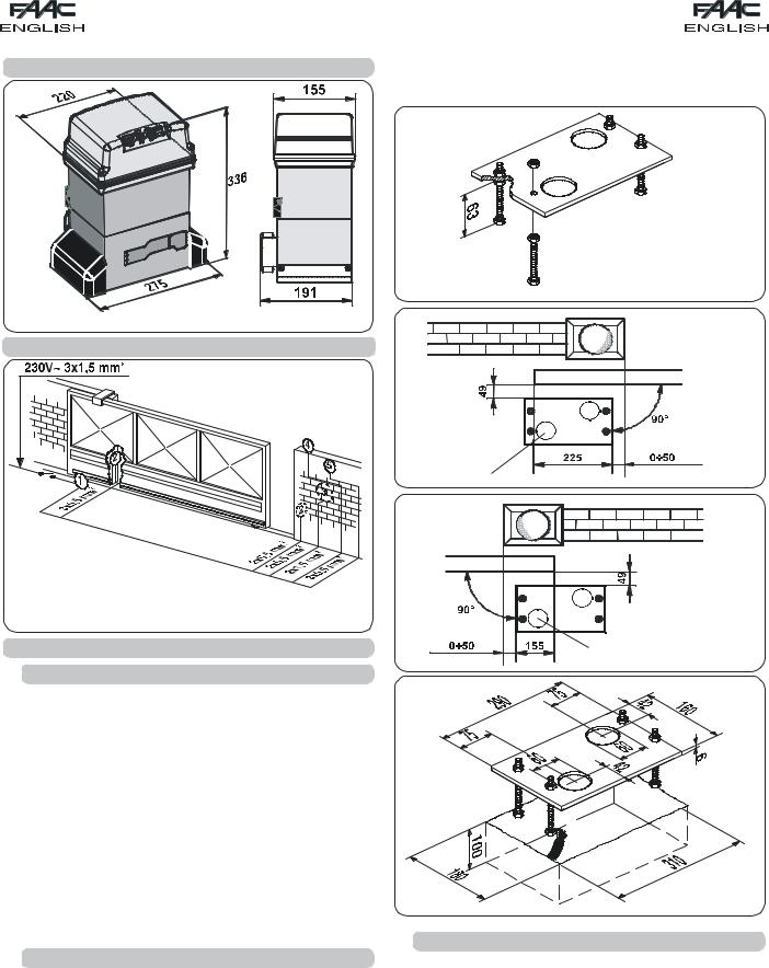
2. DIMENSIONS
Fig. 2
3. ELECTRIC EQUIPMENT (standard system)
|
Operator 746 |
|
|
with 780D equipment |
|
|
Photocells |
|
Key-operated push-button |
|
|
|
Flashing lamp |
Fig. 3 |
|
Radio receiver |
|
4. INSTALLATION OF THE AUTOMATED SYSTEM
4.1.PRELIMINARY CHECKS
To ensure safety and an efficiently operating automated system, make sure the following conditions are observed:
•Thegatestructuremustbesuitableforautomation.Thefollowing arenecessaryinparticular:wheeldiametermustbeinproportion totheweightofthegatetobeautomated,anupperguidemust be provided, plus mechanical stop limits to prevent the gate derailing.
•The soil must permit sufficient stability for the foundation plinth.
•Theremustbenopipesorelectriccablesintheplinthexcavation area.
•If the gearmotor is exposed to passing vehicles, install, if possible, adequate means of protection against accidental impact.
•Check if an efficient earthing is available for connection to the gearmotor.
4.2. MASONRY FOR FOUNDATION PLATE
1)Assemble the foundation plate as shown in figure 4.
2)The foundation plate must be located as shown in figure 5 (right closing) or figure 6 (left closing) to ensure the rack and pinion mesh correctly.
3)Prepare a foundation plinth as shown in fig.7 and wall the foundation plate, supplying one or more sheaths for routing electric cables. Using a spirit level, check if the plate is perfectly level. Wait for the cement to set.
4)Lay the electric cables for connection to the accessories and power supply as shown in figure 3.
To make the connections efficiently, allow the cables to project by about 40 cm from the hole (Figs.5-6 ref. ) of the foundation plate.
|
Fig. 4 |
|
Fig. 5 |
|
Fig. 6 |
Fig. 7
4.3. MECHANICALINSTALLATION
1)Assemble the securing corners and anti-vibration spacers on the operator as shown in Fig. 8.
2)Open the cover, unscrewing the securing screws.
3)Place the operator on the plate, using the supplied washers and nuts as shown in Fig. 9.
During this operation, route the cables through the duct inside the lower half-casing of the operator (Fig.10 - Ref. A).
To access the electronic equipment, route the cables through the appropriate hole, using the supplied rubber cable-clamp. Make absolutely sure to unsheathe all the cables so that the clamp holds single cables only (Fig.10 - Ref. B).
20

5)Secure the gearmotor to the foundation plate, tightening the nuts as in Fig.12.
6)Prepare the operator for manual operating mode as described in chapter 8.
Fig. 8
Fig. 9
A B
Fig. 10
Fig. 11
4.4.INSTALLING THE RACK
4.4.1.STEEL RACK TO WELD (Fig.13)
1)Placethethreethreadedpawlsonthe rack element, positioning them at the top of the slot. In this way, the slot play
will enable any adjustments to be made.
2) Manually take the leaf into its closing position.
3) Lay the first piece of rack level on the pinion and weld the threaded pawl on the gate as shown in figure15.
4)Move the gate manually, checking if the rack is resting on the pinion, and weld the second and third pawl.
5)Bring another rack element near to the previous one, using a piece of rack (as shown in figure 16) to synchronise the teeth of the two elements.
6)Move the gate manually and weld the three threaded pawls, thus proceeding until the gate is fully covered.
4.4.2.STEEL RACK TO SCREW (Fig. 14)
1)Manually take the leaf into its closing position.
2)Lay the first piece of rack level on the pinion and place the spacer between the rack and the gate,
positioning it at the top of the slot. 3) Mark the drilling point on the gate.
Drill a Ø 6,5 mm hole and apply thread with a Ø 8 mm male tap. Screw the bolt.
4) Move the gate manually, checking if the rack is resting on the pinion, and repeat the operations at point 3.
5)Bring another rack element near to the previous one, using a piece of rack (as shown in figure 16) to synchronise the teeth of the two elements.
6)Move the gate manually and carry out the securing operations as for the first element, thus proceeding until the gate is fully covered.
4.4.3.NYLON RACK TO SCREW (Fig.14bis)
1)Manually take the leaf into its
closing position.
2) Lay the first piece of the rack level on the pinion and mark the drilling point on the gate; drill Ø 4 mm and screw the self-tapping screw 6 x 20 mm to the relevant reinforcing plate.
3) Move the gate manually, checking if the rack is resting on the pinion, and repeat the operations at point 2.
4)Bring another rack element near to the previous one, using a piece of rack (as shown in figure 16) to synchronise the teeth of the two elements.
5)Move the gate manually and carry out the securing operations as for the first element, thus proceeding until the gate is fully covered.
21

Fig. 15
Fig. 16
Notes on rack installation
•Make sure that, during the gate travel, all the rack elements do not exit the pinion.
•Do not, on any account, weld the rack elements either to the spacers or to each other.
•When the rack has been installed, to ensure it meshes correctly with the pinion, we advise
you to lower the gearmotor position |
|
|
by about 1.5 mm (Fig.17). |
|
|
• Manually check if the gate |
|
|
habitually reaches the mechanical |
|
|
stop limits and make sure there is no |
|
|
friction during gate travel. |
|
|
• Do not use grease or other lubricants |
Fig. 17 |
|
between rack and pinion. |
||
|
4.5.INSTALLATION OF CHAIN PINIONS
In the versions for applications with chain and idle transmissions, a Z16 or Z20 chain pinion must be installed. Proceed as follows:
4.5.1.MOD. 746 ER CAT (Figs. 18 - 19)
1)Insert the spring pin on the shaft, using a hammer.
2)Fit the chain pinion on the shaft, making the pinion seats coincide with the spring pin and tighten the screw with the appropriate washers.
Fig. 19
4.5.2.MOD. 746 ER RF (Figs. 20 - 21)
1)Insert the spring pin on the shaft, using a hammer.
2)Fit the idle transmissions bracket on the gearmotor flange, using the four screws (M5 x 12) and the appropriate washers , in the kit as shown in Fig. 20.
3)Fit the chain pinion on the shaft, making the pinion seats coincide with the spring pin and tighten the screw and the appropriate washers and .
4)Pass the chain as shown in Fig. 21 ref. A and install the housing with screw and washer as in Fig. 20.
5)In case of operators with MLS limit switches, arrange the supports for the positioning of the magnets supplied while observing the dimensions given in fig. 21 ref. B.
Fig. 20
A
5÷12 mm mm0÷10 


B
Fig. 21
Fig. 18
22
 Loading...