


E145
ENGLISH
CE DECLARATION OF CONFORMITY |
|
The manufacturer |
|
Company name: |
FAAC S.p.A. Soc. Unipersonale |
Address: |
Via Calari, 10 - 40069 Zola Predosa BOLOGNA - ITALY |
hereby declares that the following product: |
|
Description: |
control board |
Model: |
E145 |
conforms to the essential safety requirements of the following ECC directives:
Low Voltage Directive 2014/35/EU
Electromagnetic Compatibility Directive 2014/30/EU Directive ROHS 2011/65/EU
Furthermore, the following harmonised standards have been applied:
EN 60335-1:2012 + A11:2014 - EN 61000-6-2:2005 - EN 61000-6-3:2007 + A1:2011 Additionalnote: this product underwent tests in a typical uniform configuration (all products
manufactured by FAAC S.p.A.).
Bologna, January the 1st 2016
1
A
 B
B
 C
C
TF1
8.8.
F
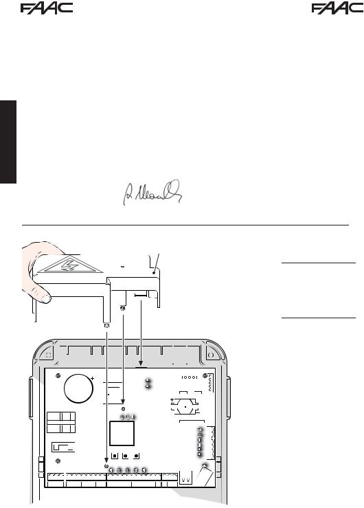
· Interrupt the electrical power sup-ply before working on the control unit. The protection cover
(1) needs to be installed before switching on the power supply.
E145 |
2 |
732784 - Rev. B |

WARNINGS FOR THE INSTALLER
GENERAL SAFETY OBLIGATIONS
1.ATTENTION! To ensure the safety of people, it is important that you read all the following instructions. Incorrect installation or incorrect use of the product could cause serious harm to people.
2.Carefully read the instructions before beginning to install the product.
3.Donotleavepackingmaterials(plastic,polystyrene, etc.) within reach of children as such materials are potential sources of danger.
4.Store the instructions for future reference.
5.This product was designed and built strictly for the use indicated in this documentation. Any other use, not expressly indicated here, could compromise the good condition/operation of the product and/or be a source of danger.
6.FAACS.p.A.declinesallliabilitycausedbyimproper use or use other than that for which the automated system was intended.
7.Do not install the equipment in an explosive atmosphere: the presence of inflammable gas or fumes is a serious danger to safety.
8.FAAC S.p.A. is not responsible for failure to observe Good Technique in the construction of the closing elements to be motorised, or for any deformation that may occur during use.
9.The installation must conform to Stan-
d a r d s E N 1 2 4 5 3 a n d E N 1 2 4 4 5 . For non-EU countries, to obtain an adequate level of safety, the Standards mentioned above must be observed, in addition to national legal regulations.
10.Before attempting any job on the system, cut out electrical power and disconnect the batteries if present.
11.Themainspowersupplyoftheautomatedsystem must be fitted with an all-pole switch with contact opening distance of 3mm or greater. Use of a 6A thermal breaker with all-pole circuit break is recommended.
12.Makesurethatadifferentialswitchwiththreshold of 0.03 A is fitted upstream of the system.
13.Make sure that the earthing system is perfectly constructed, and connect metal parts of the means of the closure to it.
14.Theautomatedsystemsthatfeatureabuilt-inanti- crushing safety device in any case require a functional check in accordance with the provisions of the Standards indicated at point 9.
15.Thesafetydevices(EN12978standard)protect any danger areas against mechanical movement Risks, such as crushing, dragging, shearing, lifting.
16.Use of at least one indicator-light (e.g.: flashing lamp) is recommended for every system, as well as a warning sign adequately secured.
17.FAACS.p.A.declinesallliabilityasconcernssafety and efficient operation of the automated system, if system components not produced by FAAC S.p.A. are used.
18.For maintenance, strictly use original parts by FAAC S.p.A.
19.Do not in any way modify the components of the automated system.
20.The installer shall provide the User with all information concerning manual operation of the system in case of an emergency.
21.Do not allow children or adults to stay near the product while it is operating.
22.Keep radio controls or other pulse generators away from children, to prevent the automated system from being activated involuntarily.
23.Transit is allowed only when the automation is fully open.
24.The User must not attempt any kind of repair or direct action whatever and contact qualified personnel only.
25.Anythingnotexpresslyspecifiedintheseinstructions is not permitted.
ENGLISH
MEANING OF THE SYMBOLS USED
|
|
|
Important for the safety of persons and for the |
|
Notes on the characteristics and operation of |
good condition of the automated system. |
|
the product. |
E145 |
3 |
732784 - Rev. B |

INDEX
ENGLISH
CE DECLARATION OF CONFORMITY ..................................................................................... |
2 |
||
WARNINGS FOR THE INSTALLER........................................................................................... |
3 |
||
1. |
TECHNICAL SPECIFICATIONS............................................................................................ |
5 |
|
2. |
PREPARING FOR INSTALLATION....................................................................................... |
6 |
|
3. |
BOARD LAYOUT................................................................................................................... |
6 |
|
4. |
ELECTRICAL CONNECTIONS ............................................................................................. |
8 |
|
4.1 |
J1 - Mains primary Power Supply................................................................................... |
8 |
|
4.2 |
J2 - Motors and Flashing lamp ....................................................................................... |
8 |
|
4.3 |
J3 - Low-voltage accessories - inputs/outputs ............................................................. |
9 |
|
4.4 |
J12 - programmable outputs - electric locks................................................................. |
10 |
|
4.5 |
J12 -J6 - LIMIT SWITCH AND GATECODER................................................................... |
10 |
|
4.6 |
J10 - BUS-2EASY ACCESSORIes .................................................................................. |
11 |
|
|
BUS-2EASY photocells........................................................................................................ |
11 |
|
|
Address assignment of BUS-2EASY photocells .................................................................. |
12 |
|
|
Connection of BUS-2EASY photocells................................................................................. |
12 |
|
|
BUS-2EASY encoder ........................................................................................................... |
13 |
|
|
Connection - Address assignment of BUS-2EASY Encoder................................................ |
13 |
|
4.7 |
J5 - XF module RAPID CONNECTOR ............................................................................. |
14 |
|
4.8 |
J14 - Decoder/Minidec/RP RAPID CONNECTOR........................................................... |
14 |
|
4.9 |
M1A - MODULe RAPID CONNECTOR............................................................................ |
14 |
|
4.10 traditional photocells..................................................................................................... |
15 |
||
5. |
PROGRAMMING ................................................................................................................... |
18 |
|
5.1 |
Basic PROGRAMMING functions ................................................................................... |
19 |
|
5.2 |
Advanced PROGRAMMING functions............................................................................ |
24 |
|
5.6 |
BUS-2EASY DEVICE INSTALLATION ............................................................................. |
30 |
|
|
5.6.1 BUS-2EASY DEVICE ENTRY....................................................................................... |
30 |
|
|
Checking the securing devices entered on the board.......................................................... |
31 |
|
5.4 |
TIME LEARNING - SETUP................................................................................................ |
32 |
|
5.5 |
TESTING THE AUTOMATED SYSTEM ............................................................................ |
33 |
|
6. |
MEMORISING THE RADIO CODE........................................................................................ |
34 |
|
6.1 |
MEMORISING THE SLH/SLH LR RADIO CONTROLS ................................................... |
34 |
|
6.2 |
MEMORISING LC/RC RADIO CONTROLS (ONLY 433 MHz) ......................................... |
35 |
|
|
6.2.1 REMOTE MEMORISATION OF LC/RC RADIO CONTROLS ................................... |
36 |
|
6.3 |
MEMORISING DS RADIO CONTROLS............................................................................ |
36 |
|
6.4 |
DELETING THE RADIO CONTROLS............................................................................... |
37 |
|
7. |
START-UP.............................................................................................................................. |
38 |
|
7.1 |
CHECKING THE LEDs...................................................................................................... |
38 |
|
8. |
SIGNALLING ERRORS AND ALARMS ................................................................................ |
39 |
|
8.1 |
ERRORS............................................................................................................................ |
39 |
|
8.2 |
ALARMS............................................................................................................................ |
40 |
|
9. |
TROUBLESHOOTING........................................................................................................... |
41 |
|
10. MANAGING THE CONFIGURATION FILE – J8 USB ....................................................... |
42 |
||
11. FUNCTION LOGICS ............................................................................................................ |
45 |
||
E145 |
4 |
732784 - Rev. B |

CONTROL BOARD E145
We thank you for having chosen one of our products. FAAC is certain that from it you will obtain all the performance you require. All our products are the result of years of experience in the field of automated systems.
1. TECHNICAL SPECIFICATIONS
PURPOSE: this electronic control board has been |
During programming you can choose between |
|
designed and built to control swing-leaf and/or |
different function logics. |
|
sliding gates for vehicle and pedestrian access |
2 programming levels are available from the bo- |
|
control. |
ard (BASIC and ADVANCED), using buttons and |
|
Thanks to the innovative power supply switching |
||
LCD display. |
||
system, the board is able to automatically adapt |
This board also allows you the programming using |
|
to different input voltages (from 90V~ to 260V~), |
PC or MAC, connected via USB-B. |
|
maintaining constant the output value of accesso- |
|
|
ries, without being affected by variations. |
|
Tab. Technical specifications |
|
|
|
|
|
|
|
Mains primary power supply |
|
With power supply switching from 90 V~ to 260 V~; 50/60Hz |
|||||
|
|||||||
Power absorbed from mains |
|
stand By = 4W |
|
sleep < 2 W * |
MAX ~ 800 W |
||
|
*FUNCTION THAT CAN BE ENABLED FROM A PC/MAC |
||||||
|
|
||||||
MAX load for motors |
|
800 W |
|
|
|
||
Accessories power supply |
|
24 V" |
|
|
|
||
|
|
+24V MAX 500 mA |
|
BUS 2easy MAX 500 mA |
|||
MAX. accessories current |
|
LOCK (FAAC) 12 V~ / 24 V" |
LOCK (not FAAC) 24 V" |
||||
|
|
|
|
|
|
500mA (3A peak) |
|
Operating ambient temperature |
|
from -20°C to +55°C |
|
|
|
||
Power supply safety fuses |
|
F1 = F10AH250V |
|
|
|
||
Work time |
|
Self-learned through SETUP - (Max 4 min and 10 sec) |
|||||
Pause time |
|
Programmable (from 0 to 9 min and 50 sec) |
|||||
Motor power |
|
Programmable on 50 levels |
|
||||
Connector inputs |
|
Decoder/Minidec/RP, XF433/868 Module, USB-A, USB-B |
|||||
Terminal board inputs |
|
Mains power supply from 90 to 260V ~, Inputs from IN1 to |
|||||
|
IN5, Limit switch, BUS 2easy |
|
|||||
|
|
|
|||||
|
|
|
|
|
|
|
|
Terminal board outputs |
|
Flashing lamp, Motors, Electric lock (LOCK1 and LOCK2), |
|||||
|
OUT1 and OUT2 (programmable),Accessories power supply |
||||||
|
|
||||||
|
|
|
|
|
|
|
|
ENGLISH
E145 |
5 |
732784 - Rev. B |

2. PREPARING FOR INSTALLATION
For safety reasons, it is important for people to carefully follow all the warnings and instructions contained in this manual. Incorrect installation or incorrect use of the product can cause serious harm to people. Before proceeding with product installation, carefully read the entire manual. Keep these instructions for further reference.
Always cut off the electrical power before carrying out any work on the control unit (connections, maintenance).
Always separate the power cables from the control and safety cables (button, receiver, BUS 2easy encoder, photocells, etc.). Avoid any electrical disturbance using separate sheathing or a shielded cable (with shield connected to the earth).
ENGLISH |
• |
Ensure that upstream of the system there is a suitable magnetothermic differential switch with |
||||
|
omnipolar cut-off, as provided for in current safety regulations. |
|
||||
|
|
|
||||
|
• |
Check for the presence of an adequate earthing system. |
|
|
||
|
3. BOARD LAYOUT |
|
|
|
|
|
|
|
|
|
|
|
RP/DEC |
|
|
|
|
RADIO 1 |
J5 |
|
|
|
|
|
DL11 |
J5 |
|
|
|
|
|
DL11RADIO 2 |
RADIO XF 433-868 |
|
|
|
C52 |
|
DL12 |
|
|
|
DB1 |
|
DL12 |
|
|
|
|
|
TF1 |
|
|
CONNECTIVITY |
J4J4 |
|
|
|
|
|
||
|
|
|
|
|
BAT1 |
|
|
|
DL16 |
DL17DL17 |
L13 |
CR2032 BAT1 |
|
|
|
DL16 |
|
DL13 |
M1A |
|
|
|
5V |
24V |
ERROR |
|
|
FL1

1 |
F1 |
OC4 |
OC3 |
8.8.L 1 |
|
|
IC1 |
TH2 |
TH1 |
LCD |
|
|
+/R1 -/R2 F |
|
|
|
RL1 |
RL2 |
|
RL3 |
RL4 |
RL5 |
|
|
SW1 |
|
SW2 |
|
SW3 |
|
|
|
|
|
|
|
|
||
|
|
|
|
|
|
SW1 SW2 |
SW3 |
|
|
|
|
|
|
|
|
||||||||||
|
|
|
|
|
|
|
|
|
|
|
|
|
|
|
|
|
|
|
|
||||||
|
|
|
|
|
|
|
|
|
|
|
|
9 |
8 |
|
7 |
|
L6 |
L5 |
|
|
|
|
|
|
|
|
|
|
|
|
|
|
|
|
|
|
DL9 DL8 |
DL7 |
DL6 |
DL5 |
|
|
|
|
|
|
|||||
J1 |
|
|
2 |
|
|
|
|
|
|
|
J3 |
IN1 |
IN2 |
|
IN3 |
|
IN4 |
IN5 |
|
|
|
|
J |
|
|
|
|
J2 |
|
|
|
|
|
|
|
|
|
|
|
|
|
|
|
|
|
|
J12 |
|
|
||
PE |
N |
L 1 |
2 |
3 |
4 |
5 |
6 |
7 |
8 |
9 10 11 12 13 14 15 16 17 18 19 |
20 21 22 |
||||||||||||||
PE |
N |
L |
1 |
2 |
3 |
4 |
5 |
6 |
7 |
8 |
9 |
10 |
11 |
12 |
13 |
14 |
15 |
16 |
17 |
18 |
19 |
20 |
21 |
22 |
|
COM |
M1 |
CL |
COM |
M2 |
CL |
LAMP |
IN1 |
IN2 |
IN3 |
IN4 |
IN5 |
- |
- |
- |
+ |
24V |
+ |
OUT1 |
OUT2 |
LOCK LOCK |
|||||
ACMAIN |
|
OP |
OP |
OP-A OP-B |
STOP |
CL FSW OP |
|
|
|
|
|
|
|
1 |
2 |
||||||||||
BUS MON.J10 |
|||
DL14 BUS |
|
0 |
|
DL |
|
|
|
DL15 |
|
|
|
DL |
FCA2FCC2FCC1 FCA1 |
|
242526 23 |
DL1 |
26 |
||
DL4 |
|
23 |
|
DL3 |
|
24 |
|
D |
|
25 |
|
DL2 |
|
|
|
|
DL10 |
J6 |
|
DL10 |
|
J6 |
|
|
USB |
||
J8 |
|
|
|
J8 |
|
|
|
|
|
|
J9 |
USB-A |
|
|
USB-B |
E145 |
6 |
732784 - Rev. B |

LCD Signalling/Programming display
SW1 “+/R1” Programming button
SW2 “-/R2” Programming button
SW3 “F” Programming button
DL1 “FCC2” Input status control LED
DL2 “FCA2” Input status control LED
DL3 “FCC1” Input status control LED
DL4 “FCA1” Input status control LED
DL5 “IN5” Input status control LED (default FSW OP)
DL6 “IN4” Input status control LED (default FSW CL)
DL7 “IN3” Input status control LED (default STOP)
DL8 “IN2” Input status control LED (default OPEN-B)
DL9 “IN1” Input status control LED (default OPEN-A)
DL10 “USB” Signalling LED
DL11 “RADIO1-XF” Signalling LED (OMNIDEC)
DL12 “RADIO2-XF” Signalling LED (OMNIDEC)
DL13 “ERROR” Error/alarm signalling LED
DL14 LED“BUS MON” BUS 2easy diagnostic signalling
DL15 Device signalling LED to BUS 2easy ACTIVE
DL16 |
Microprocessor power presence LED |
|
|
|
|
|
|
DL17 |
+24V"Accessories power supply presence |
||
|
LED |
|
|
J1 |
90V~ a 260V~ Power supply connector |
||
|
|
|
|
J2 |
Motors and flashing lamp power supply |
||
connector |
|||
|
|||
|
|
|
|
J3 |
Input/Output connector |
||
|
|
|
|
|
Decoder/Minidec/RP Receiver connector: |
||
J4 |
Channel1 (Decoder/Minidec/RP) - OPEN A |
||
(Total Opening) |
|||
|
|||
|
Channel2(RP2) - OPENB (Partial Opening) |
||
|
|
|
|
|
XF433/XF868 (OMNIDEC) receiver module |
||
J5 |
connector |
||
|
|
||
Channel 1 - OPEN A (Total Opening) |
|||
|
|||
|
|
||
|
Channel 2 - OPEN B (Partial Opening) |
|
|
|
|
|
|
J6 |
Limit switch input connector |
||
|
|
|
|
J8 |
HOST USB-A for Mass Memories connector |
||
|
|
|
|
J9 |
DEVICE USB-B for connection to PC/MAC |
||
connector |
|||
|
|||
|
|
|
|
J10 |
BUS 2easy device connector |
||
|
|
|
|
J12 |
OUT2 and LOCK 1-2 output connector |
||
|
|
|
|
M1A |
G-COM, WI-COM, Net-COM module con- |
||
nector |
|||
|
|
|
|
BAT1 |
CR2032 buffer battery for board date/time |
||
|
|
|
|
F1 |
Motor and power supply safety fuse |
||
|
|
|
|
ENGLISH
E145 |
7 |
732784 - Rev. B |
ENGLISH
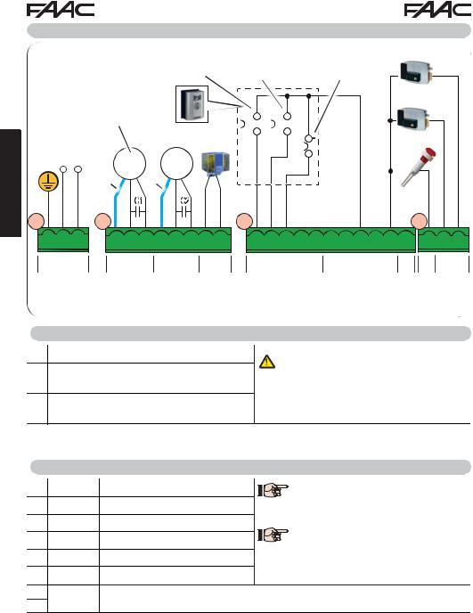
4. ELECTRICAL CONNECTIONS
|
|
OPEN A |
|
OPEN B |
||||||
|
|
Total gate opening |
Partial gate ope- |
|||||||
|
|
(contact N.O.) |
ning (contact N.O.) |
|||||||
|
Motor for SINGLE-LEAF or |
|
|
|
|
|
|
|
|
|
|
FIRSTLEAF when opening |
|
|
|
|
|
|
|
|
|
|
(closes for the second) |
230V~ |
|
|
|
|
|
|
|
|
|
|
|
|
|
|
|
|
|||
|
MIN 90V~ |
|
|
|
|
|
|
|
|
|
|
|
|
|
|
|
|
|
|
||
|
MAX 260V~ |
|
MAX 60W |
|
|
|
|
|
|
|
|
|
|
|
|
|
|
|
|
||
|
50/60Hz |
Mot1 Mot2 |
|
|
|
|
|
|
|
|
|
|
|
|
|
|
|
|
|||
|
|
|
|
|
|
|
|
|
||
|
* |
* |
|
|
|
|
|
|
|
|
|
|
C1 |
C2 |
|
|
|
|
|
|
|
J1J1 |
J2J2 |
|
|
J3J3 |
||||||
STOP |
|
12V |
~ |
|
Gate stop |
|
24V |
|
|
(contact |
|
|
|
|
N.C.) |
|
|
|
|
|
|
12V |
~ |
|
|
|
24V |
|
|
|
24V |
|
|
|
|
3W |
|
|
|
|
|
|
|
|
J12
PE |
N |
L |
1 2 3 4 5 6 |
7 |
8 |
9 10 11 12 13 14 15 16 17 18 19 |
20 21 22 |
||||||||||||
PE |
N |
L |
1 2 |
3 4 5 6 |
7 |
8 |
9 |
10 |
11 |
12 |
13 |
14 |
15 |
16 |
17 |
18 |
19 |
20 21 |
22 |
ACMAIN |
M1 |
M2 |
LAMP |
IN1 |
IN2 |
IN3 |
IN4 |
IN5 |
- |
- |
- |
+ |
+ |
OUT1 |
OUT2 LOCK LOCK |
||||
|
|
|
COM OP CL COM OP CL |
|
|
OP-A OP-B STOP CLFSWOP |
|
|
|
24V |
|
1 |
2 |
||||||
|
*Blue or grey |
|
|
|
|
|
|
{ { { |
|
||||||||||
|
|
Photocells and safety de- |
|
|
MAX |
|
MAX |
|
|||||||||||
|
|
|
|
vices: for connections, see |
|
500 mA |
|
100 mA |
|
||||||||||
|
|
|
|
|
the related paragraph. |
|
|
|
|
||||||||||
|
|
|
|
|
|
|
|
|
|
|
|
|
|
||||||
4.1 J1 - MAINS PRIMARY POWER SUPPLY
PE Earthing Connection
NPower Supply Connection from 90 V~ to 260 V~ Neutral
LPower Supply Connection from 90 V~ to 260 V~ Line
For correct operation, you must connect the switching power supply to the system’s earthing conductor. Ensure that upstream a suitable differential magnetothermic switch has been installed.
4.2 J2 - MOTORS AND FLASHING LAMP
1 |
M1 |
- COM |
Common contact motor 1 |
M1=firstleafwhenopeningorsingleleaf |
|
2 |
M1 |
- OP |
Opening phase motor 1 |
M2 = second leaf when opening - CAN- |
|
3 |
M1 |
- CL |
Closing phase motor 1 |
NOT be used for single leaf |
|
To verify correct wiring and direction |
|||||
4 |
M2 |
- COM Common contact motor 2 |
|||
of motor rotation, (see 5.4 TIME LEAR- |
|||||
5 |
M2 |
- OP |
Opening phase motor 2 |
NING - SETUP) |
|
6 |
M2 |
- CL |
Closing phase motor 2 |
|
|
7 |
LAMP |
Flashing lamp connection (MAX 60 W) |
|
||
8 |
|
||||
|
|
|
|
||
E145 |
8 |
732784 - Rev. B |

4.3 J3 - LOW-VOLTAGE ACCESSORIES - INPUTS/OUTPUTS
9 |
IN1 |
OPEN A contact - N.O. |
Connect a button or other pulse generator which, by closing |
|
TOTAL opening |
a contact, commands TOTAL opening of both leaves. |
|||
|
|
|||
|
|
|
Connect a button or other pulse generator which, by closing |
|
|
|
|
a contact, commands the PARTIAL opening. |
|
|
|
OPEN B contact - N.O. |
on 2-motor systems = 100% of leaf 1 opening; |
|
10 |
IN2 |
on 1-motor systems = 50% of leaf 1 opening. |
||
|
|
PARTIAL opening |
When a logic requiring a CLOSE ( b, bC, C) input is selected, |
|
|
|
|
||
|
|
|
the, OPEN B input automatically becomes CLOSE - N.O. (lea- |
|
|
|
|
ves closing command). |
To install more than one OPEN A or OPEN B pulse generator, connect the N.O. contacts in parallel (see related Fig.)
11 |
IN3 |
STOP contact - N.C. |
Connect a button or other pulse generator which, by opening |
|
a contact, stops movement of the automated system. |
||||
|
|
|
To install more than one STOP device, connect the N.C. contacts in series (see related Fig.).
If stop devices are NOT connected, jumper the terminals STOP and GND.
12 |
IN4 |
FSW CL contact - N.C. |
Connect a photocell or other device which, by opening a con- |
|
closing safety |
||||
|
|
tact, reverses the movement of the automated system during |
||
13 |
IN5 |
FSW OP contact - N.C. |
||
opening (FSW OP) or during closing (FSW CL). |
||||
opening safety |
||||
|
|
|
To install more than one safety device, connect the N.C. contacts in series (see related Fig.).
If safety devices are NOT connected, jumper terminals IN4 and IN5 and GND if the FAIL-SAFE safety is not active; otherwise jumper IN4 and IN5 and OUT1 (FAIL-SAFE).
14 |
|
|
|
|
15 |
- |
GND Accessories power supply negative |
||
16 |
|
|
|
|
17 |
+ |
+24 Accessories power supply positive (MAX. load = 500mA) |
||
18 |
||||
|
|
|
||
19 |
OUT1 |
24 V" (Open Collector) programmable using function o1 (advanced programming); |
|
|
|
|
default: always active. |
|
|


 Other programming options are available by programming via a PC/MAC (see dedicated instructions).
ENGLISH
Fig. e.g.: Connecting 2 N.O. contacts in parallel.
Fig. e.g.: Connecting 2 N.C. contacts in series.
E145 |
9 |
732784 - Rev. B |

ENGLISH
4.4 J12 - PROGRAMMABLE OUTPUTS - ELECTRIC LOCKS
20 |
OUT2 |
24 V"(Open Collector) programmable using the function o2 (advanced programming); |
|
|
|
default: indicator light |
|
21 |
LOCK 1 |
Electric lock (12 V~ or 24 V") |
When BUS 2easy encoder is disabled, the electric |
operated 2 sec before opening |
lock is operated before each opening (in whatever |
||
|
|
of leaf 1 |
position the stopped leaf is in). |
22 |
LOCK 2 |
Electric lock (12 V~ or 24 V") - |
When BUS 2easy encoder is enabled, the electric |
operated 2 sec before opening |
|||
|
|
of leaf 2 |
lock is operated only before opening the closed leaf. |
|
|
|
|
|
|
|
|

 Other programming options are available by programming via a PC/MAC (see dedicated
 instructions).
4.5 J12 -J6 - LIMIT SWITCH AND GATECODER
The limit switch contacts FCC1, FCA1, FCC2, FCA2 are all NC contacts.
They are programmable using the functions FA and FC (basic programming) ; default: disabled.

 If no limit switches are used, you DO NOT need to jumper the limit switch contacts
FCC1, FCA1, FCC2, FCA2.
You can however use a single GATECODER (only for single leaf); in this case, you do not need to jumper the unused inputs to the earth.
Fig. Limit switch and GATECODER connections (maximum configuration: ).
23 |
FCA1 |
|
24 |
FCC1 |
|
25 |
||
FCA2 |
||
26 |
||
FCC2 |
||
|
J6J6


GATECODER 1


GATECODER 2 
GATECODER 1
GATECODER 2
FCA1, FCC1 and GATECODER1 correspond to LEAF 1; FCA2, FCC2 and GATECODER2 correspond to LEAF 2.
23 |
FCA1 |
|
24 |
FCC1 |
|
25 |
||
FCA2 |
||
26 |
||
FCC2 |
||
|
||
J6 |
|
|
23 |
FCA1 |
|
24 |
FCC1 |
|
25 |
||
FCA2 |
||
26 |
||
FCC2 |
||
|
J6
E145 |
10 |
732784 - Rev. B |
4.6 J10 - BUS 2EASY ACCESSORIES
This board features a BUS2easy circuit for facilitating connection to the safety devices of a high number of auxiliary BUS 2easy (MAX 16 pairs of photocells), encoder and control devices.

 If no BUS 2easy accessories are used, leave the BUS 2easy connector free.
BUS 2easy photocells
Before connecting the photocells, arrange them for the duly address assignment, depending on their position and operation mode:
Photocells during closing: trip only during the closing of the automated system - suitable for protecting the closing area from risk of impact.
Photocells during opening: trip only during the opening of the automated system - suitable for protecting the opening area from risk of impact.
Photocells during opening/closing: trip during both the opening and closing - suitable for protecting the entire movement area from risk of impact.
Pulse generators: used as pulse generators for opening the automated system.
Opening/closing safety devices
Closing
safety devices
Opening safety devices
ENGLISH
E145 |
11 |
732784 - Rev. B |

Address assignment of BUS 2easy photocells
To assign the address to each pair of photocells, you must set the Dip-Switches (DS1) located on the transmitter and corresponding receiver.
 The transmitter and receiver of a pair of photocells must have the same
DIP-SWITCH setting.
Two or more pairs of photocells must not have the same DIP-SWITCH setting.

 Other programming options are available by programming via a PC/MAC (see dedicated
 instructions).
ENGLISH
Dip1 |
Dip2 |
Dip3 |
Dip4 |
TYPE OF PHOTOCELLS |
|
|
|
|
|
|
|
OFF |
OFF |
OFF |
OFF |
|
|
OFF |
OFF |
OFF |
ON |
|
|
OFF |
OFF |
ON |
OFF |
OPENING (max 6 pairs) |
|
OFF |
OFF |
ON |
ON |
||
|
|||||
OFF |
ON |
ON |
OFF |
|
|
OFF |
ON |
ON |
ON |
|
|
ON |
OFF |
OFF |
OFF |
|
|
ON |
OFF |
OFF |
ON |
|
|
ON |
OFF |
ON |
OFF |
|
|
ON |
OFF |
ON |
ON |
CLOSING (max 7 pairs) |
|
|
|
|
|
|
|
ON |
ON |
OFF |
OFF |
|
|
ON |
ON |
OFF |
ON |
|
|
ON |
ON |
ON |
OFF |
|
|
OFF |
ON |
OFF |
OFF |
OPENING and CLOSING (max 2 pairs) |
|
OFF |
ON |
OFF |
ON |
||
|
|||||
ON |
ON |
ON |
ON |
OPEN PULSE (1 pair) |
Connection of BUS 2easy photocells
For connecting you have to use two cables without polarity (see the specific device instructions).
DL1= Alignment
DL2= BUS 2easy status/
Power supply
DS1= Programming
Dip-switches
BUS 2easy
J10
E145 |
12 |
732784 - Rev. B |

BUS 2easy encoder
BUS 2easy encoder connection is done using the bi-polar cables supplied with.
Connection - Address assignment of BUS 2easy Encoder
The polarity of the BUS 2easy line connection determines the correspondence of the encoder to one leaf or the other.
pay careful attention to the indications of the status LEDs located on the body of each encoder.
LEAF 1 opens first and closes last.
|
A |
|
SAFEcoder |
|
|
|
|
|
S800 ENC |
|||||
|
|
|
|
|
|
|
|
|
||||||
|
|
|
|
|
|
|
|
|
|
|
|
|
|
|
|
|
|
|
|
|
|
J10 |
|
|
|
||||
|
|
|
|
|
|
|
BUS-2easy |
|
|
|
||||
|
|
|
|
|
|
|
|
|
|
|
DL3 |
|
|
DL3 |
|
|
|
|
|
|
|
|
|
|
|
|
|||
|
|
|
|
|
|
|
|
|
|
|
DL2 |
|
|
DL2 |
|
|
|
|
|
|
|
|
|
|
|
|
|||
|
|
DL1 |
|
|
DL1 |
|
|
|
|
DL1 |
|
|
DL1 |
|
|
|
|
|
|
|
|
|
|
||||||
|
|
|
|
|
||||||||||
|
|
|
|
|
|
|
|
|
||||||
|
|
DL2 |
|
|
DL2 |
|
|
|
|
|
|
|
|
|
|
|
|
|
|
|
|
|
|
|
|
||||
|
|
DL3 |
|
|
DL3 |
|
|
|
|
|
|
|
|
|
|
|
|
|
|
|
|
|
|
|
|
||||
|
|
|
|
|
|
|
|
|
|
|
||||
J10
BUS-2easy
ENGLISH
|
|
|
|
|
|
|
|
|
|
|
|
|
|
|
|
|
|
|
|
|
|
|
|
|
|
|
|
|
|
|
|
|
|
|
|
|
|
|
|
|
|
|
|
||
|
|
|
|
|
|
|
|
|
|
|
|
|
|
|
|
|
|
|
|
|
|
|
|
|
|
|
|
|
|
|
|
|
|
|
|
|
|
|
|
|
|
|
|
|
|
|
M1 : 2 LED on |
|
|
|
|
|
|
|
|
|
|
|
|
|
|
|
|
|
|
|
|
|
B |
|
|
|
|
|
|
|
|
|
|
|
|
|
|
|
|
|
|
|
|
||
|
|
|
|
|
|
|
|
|
|
|
|
|
|
|
|
|
|
|||||
|
|
|
|
|
|
|
|
|
|
|
|
|
|
|
|
|
|
|||||
|
M2 : 1 LED on |
|
|
|
|
|
M2 |
|
|
|
M1 |
|
|
|
|
|
|
|||||
|
|
|
DL1 |
|
|
|
|
|
|
DL1 |
|
|||||||||||
|
|
|
|
|
|
|
|
|
|
|
|
|
|
|||||||||
|
|
|
|
|
|
|
|
|
|
|
||||||||||||
|
|
|
|
|
|
|
DL2 |
|
|
|
|
|
|
|
|
|
|
|
DL2 |
|
||
|
|
|
|
|
|
|
|
|
|
|
|
|
|
|
|
|
|
|||||
|
|
|
|
|
|
|
|
|
|
|
|
|
|
|
|
|
|
|||||
|
|
|
|
|
|
|
DL3 |
|
|
|
|
|
|
|
|
|
|
|
DL3 |
|
||
|
|
|
|
|
|
|
|
|
|
|
|
|
|
|
|
|
|
|||||
|
|
|
|
|
|
|
|
|
|
|
|
|
|
|
|
|
|
|||||
|
|
|
|
|
|
|
|
|
|
|
|
|
|
|
|
|||||||
|
|
|
|
|
|
|
|
|
|
|
|
|
|
|
|
|
|
|
|
|
||
|
|
|
|
|
|
|
|
|
|
|
|
|
|
|
|
|
|
|
|
|
|
|
|
|
|
|
|
|
|
|
|
|
|
|
|
|
|
|
|
|
|
|
|
|
|
|
|
|
|
|
|
|
|
|
M1 |
|
|
|
M2 |
|
|
|
|
|
|
|||
|
|
|
|
|
|
|
DL1 |
|
|
|
|
|
|
DL1 |
|
|||||||
|
|
|
|
|
|
|
|
|
|
|
|
|||||||||||
|
|
|
|
|
|
|
DL2 |
|
|
|
|
|
|
|
|
|
|
|
DL2 |
|
||
|
|
|
|
|
|
|
|
|
|
|
|
|
|
|
|
|
|
|
||||
|
|
|
|
|
|
|
DL3 |
|
|
|
|
|
|
|
|
|
|
|
DL3 |
|
||
|
|
|
|
|
|
|
|
|
|
|
|
|
|
|
|
|
|
|
||||
|
|
|
|
|
|
|
|
|
|
|
|
|
|
|
|
|
|
|
||||
· Note: to correct the coupling of the encoder with motor M1 or M2, swap both wires on the terminals.
E145 |
13 |
732784 - Rev. B |
ENGLISH
Tab. BUS 2easy Encoder LEDs Status
LED |
ON |
FLASHING |
OFF |
|
Power present |
Power present |
Power absent |
DL1 |
Communication present |
Communication absent |
Communication absent |
|
DL1 must always be on to confirm correct encoder/board connection. |
||
|
Leaf 1 |
/ |
Leaf 2 |
DL2 DL2 indicates the leaf on which the encoder is installed; it must be on for leaf 1 and off for leaf 2.
|
Stationary leaf |
Leaf in motion |
Stationary leaf |
DL3 DL3 indicates pulse reading during leaf movement using steady flashing. In stationary status |
|||
|
of the leaf, the DL3 can be either on or off. |
|
|

 In case of incorrect connection (DL2 on or off for both of the encoders), during the
 BUS 2easy accessories learning procedure, the DL1 leds of both encoders are FLASHING.
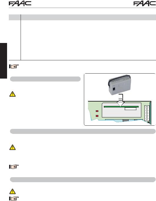
4.7 J5 - XF MODULE RAPID CONNECTOR
Plug-in rapid connector dedicated to OMNIDEC 2-channel decoding module.
ALWAYS cut off power to the board BEFORE inserting/removing the module.
|
|
RP/DEC |
|
RADIO 1 |
|
J5 |
|
DL11 |
RADIO XF 433-868 |
||
RADIO 2 |
|||
|
|
||
DL12 |
|
|
|
|
CONNECTIVITY |
J4 |
|
4.8 J14 - DECODER/MINIDEC/RP RAPID CONNECTOR
Rapid connector dedicated to Decoder/Minidec/RP/RP2.
Connect the accessory with the components facing inside the board.
ALWAYS cut off power to the board BEFORE inserting/removing plug-in boards.
The RP2 2-channel receiver lets you control two different radio channels of the automated system (OPEN A and OPEN B/CLOSE) using a 2-channel radio control.
The 1-channel receiver (Decoder/Minidec/RP) lets you control only one radio channel: OPEN A.

 Other programming options are available by programming via a PC/MAC (see dedicated
 instructions).
4.9 M1A - MODULE RAPID CONNECTOR
Plug-in connector dedicated to G-COM, WI-COM, Net-COM modules.
ALWAYS cut off power to the board BEFORE inserting/removing the module.

 Other programming options are available by programming via a PC/MAC (see dedicated
 instructions).
E145 |
14 |
732784 - Rev. B |

4.10 TRADITIONAL PHOTOCELLS
This board lets you use traditional photocells (contact N.C. with relay).
Before connecting the photocells, it is best to identify the operating type, which depends on the movement area they have to protect:
Closing photocells: trip only during the automated system closing - suitable for protecting the closing area from risk of impact.
Opening photocells: trip only during the automated system opening - suitable for protecting the opening area from risk of impact.
Photocells for opening/closing: trip during both the opening and closing - suitable for protecting the entire movement area from risk of impact.
Pulse generators: used as pulse generators for opening the automated system.
Safety devices for opening/closing
Closing safety devices
Opening safety devices
ENGLISH
Fail Safe function
This function lets you monitor the correct alignment and operation of the photocells before each movement. To enable the Fail Safe function, enter the ADVANCED Programming and set the o1 = 01 function.

 With Fail Safe disabled: connect the transmitter (TX) power supply to terminals 15 and
18 of J3.
With Fail Safe enabled: connect the power supply negative of the transmitters (TX) to OUT1. Then jumper the unused safety inputs with OUT1.
Hereafter are provided the drawings for some connection examples.
No safety device and no stop device
FAIL SAFE disabled
9 10 11 12 13 |
14 15 16 17 18 |
19 |
20 |
|
21 22 |
|||||||
|
||||||||||||
IN1 IN2 |
IN3 |
IN4 IN5 |
- - - + 24V+ |
OUT1 |
OUT2 |
|
LK1 LK2 |
|||||
OP-A OP-B |
STOP |
CL FSW OP |
|
|||||||||
9 10 11 12 13 14 15 16 17 18 19 |
20 21 22 |
|||||||||||
|
|
|
|
|
|
|
|
|
|
|
|
|
|
|
|
|
|
|
|
|
|
|
|
|
|
|
|
|
|
|
|
|
|
|
|
|
|
|
No safety device and no stop device
FAIL SAFE enabled
9 10 11 12 13 14 15 16 17 18 19 |
20 21 22 |
|||||
IN1 IN2 |
IN3 |
IN4 IN5 |
- |
- |
+ 24V+ OUT1 |
OUT2 LK1 LK2 |
OP-A OP-B |
STOP |
CL FSW OP - |
||||
9 10 11 12 13 14 15 16 17 18 19 |
20 21 22 |
|||||
E145 |
15 |
732784 - Rev. B |

One closing safety device, one opening safety device, one STOP device.
FAIL SAFE disabled
One closing safety device, one opening safety device, one STOP device.
FAIL SAFE enabled
9 10 11 12 13 |
14 15 16 17 18 |
19 |
|
20 |
|
21 22 |
|
|
|||||
IN1 IN2 IN3 IN4 IN5 |
- - - + 24V+ |
OUT1 |
|
OUT2 |
|
LK1 LK2 |
OP-A OP-B STOP CL FSW OP |
|
|
9 10 11 12 13 |
14 15 16 17 18 |
19 |
|
20 |
|
21 22 |
|
|
|||||
IN1 IN2 IN3 IN4 IN5 |
- - - + 24V+ |
OUT1 |
|
OUT2 |
|
LK1 LK2 |
OP-A OP-B STOP CL FSW OP |
|
|
9 10 11 12 13 14 15 16 17 18 19 |
20 21 22 |
9 10 11 12 13 14 15 16 17 18 19 |
20 21 22 |
ENGLISH
|
One pair of closing photocells. |
|
|
|
|
One pair of closing photocells, one pair of |
||||||||||||||||||||||||||||||
|
FAIL SAFE disabled |
|
|
|
|
opening photocells and one pair for opening/ |
||||||||||||||||||||||||||||||
|
|
|
|
|
|
|
|
|
|
|
|
|
|
|
|
|
|
|
|
|
|
|
|
closing. |
|
|
|
|
|
|
|
|
|
|
||
|
9 10 11 12 13 |
|
14 15 16 17 18 |
|
19 |
|
|
20 |
|
21 22 |
|
FAIL SAFE disabled |
|
|
|
|||||||||||||||||||||
|
|
|
|
|
|
|
|
|
|
|
|
|
|
|
|
|
|
|
|
|||||||||||||||||
|
IN1 |
IN2 |
IN3 |
IN4 IN5 |
|
- - - + 24V+ |
|
OUT1 |
|
|
OUT2 |
|
LK1 LK2 |
|
|
|
|
|
|
|
|
|
|
|
|
|
|
|||||||||
|
OP-A |
OP-B |
STOP |
CL FSW OP |
|
|
|
|
|
|
|
|
|
|
|
|
|
|
|
|
|
|
|
|||||||||||||
|
|
|
|
|
|
|
|
|
|
|
|
|
|
|
|
|
|
|
|
|
|
|
|
|
9 10 11 12 13 |
14 15 16 17 18 |
19 |
20 |
21 22 |
|
||||||
|
|
|
|
|
|
|
|
|
|
|
|
|
|
|
|
|
|
|
|
|
|
|
|
|
IN1 IN2 IN3 |
IN4 IN5 |
|
|
|
|
|
|||||
|
9 10 11 12 13 14 15 16 17 18 19 |
|
|
20 21 22 |
|
|
OP-A OP-B STOP |
CL FSW OP |
- - - + 24V+ |
OUT1 |
OUT2 |
LK1 LK2 |
|
|||||||||||||||||||||||
|
|
|
|
|
|
|
|
|
|
|
|
|
|
|
|
|
|
|
|
|
|
|
|
|
9 10 11 12 13 14 15 16 17 18 19 |
20 21 22 |
|
|||||||||
|
|
|
|
|
|
|
|
|
|
|
|
|
|
|
|
|
|
|
|
|
|
|
|
|||||||||||||
|
|
|
|
|
|
|
|
|
|
|
|
|
|
|
|
|
|
|
|
|
|
|
||||||||||||||
|
|
|
|
|
|
|
|
|
|
|
|
|
|
|
|
|
|
|
|
|
|
|
|
|
|
|
|
|
|
|
|
|
|
|
|
|
|
|
|
|
|
|
|
|
|
|
|
|
|
|
|
|
|
|
|
|
|
|
|
|
|
|
|
|
|
|
|
|
|
|
|
|
|
|
|
|
|
|
|
|
|
|
|
|
|
|
|
|
|
|
|
|
|
|
|
|
|
|
|
|
|
|
|
|
|
|
|
|
|
|
|
|
|
|
|
|
|
|
|
|
|
|
|
|
|
|
|
|
|
|
|
|
|
|
|
|
|
|
|
|
|
|
|
|
|
|
|
Other |
RX CL |
TX CL |
|
safety |
1 |
1 |
|
devices |
2 |
||
|
|
|
|
|
3 |
2 |
+ |
4 |
|||
+ |
5 |
|
|
One pair of closing photocells.
FAIL SAFE enabled
9 10 11 12 13 |
14 15 16 17 18 |
19 |
20 |
|
21 22 |
|||||||||||||
|
||||||||||||||||||
IN1 IN2 |
IN3 |
IN4 IN5 |
- - - + 24V+ |
OUT1 |
OUT2 |
|
LK1 LK2 |
|||||||||||
OP-A OP-B |
STOP |
CL FSW OP |
|
|||||||||||||||
|
|
|
|
|
|
|
|
|
|
|
|
|
|
|
|
|
|
|
9 10 11 12 13 14 15 16 17 18 19 |
20 21 22 |
|||||||||||||||||
|
|
|
|
|
|
|
|
|
|
|
|
|
|
|
|
|
|
|
|
|
|
|
|
|
|
|
|
|
|
|
|
|
|
|
|
|
|
|
|
|
|
|
|
|
|
|
|
|
|
|
|
|
|
|
|
|
|
|
|
|
|
|
|
|
|
|
|
|
|
|
|
|
|
|
|
|
|
|
|
|
|
|
|
|
|
|
|
|
|
|
|
|
|
|
|
|
|
|
|
|
|
|
|
|
|
|
|
|
|
|
|
|
|
|
|
RX CL |
TX CL |
|
|
|
1 |
|
|
|
|
2 |
1 |
|
|
|
3 |
||
|
|
2 |
+ |
|
|
+ |
4 |
||
|
5 |
|
|
|
|
|
TX OP/CL |
RX OP/CL |
|
|
|
1 |
|
|
|
1 |
2 |
|
|
3 |
|
|||
+ |
2 |
|
||
4 |
||||
|
|
5 |
+ |
|
|
RX OP |
TX OP |
|
|
|
1 |
|
|
|
|
2 |
1 |
|
|
|
3 |
|||
|
2 |
+ |
||
4 |
||||
+ |
5 |
|
|
Other |
RX CL |
TX CL |
|
|
|
||
safety |
1 |
|
|
2 |
|
|
|
devices |
3 |
1 |
|
|
4 |
2 |
+ |
+ |
5 |
|
|
E145 |
16 |
732784 - Rev. B |
 Loading...