


Dräger Medizintechnik |
|
|
|
For internal use only. Copyright reserved.
F6150000T01IVZ.fm
Contents
Function Description
A |
|
|
|
|
|
1 |
Caleo |
|
|
5 |
|
|
|
|
|
|
|
||||
|
|
|
|
|
|
|
||||
B |
|
|
|
|
|
|||||
|
|
|
|
|||||||
|
|
|
|
|
||||||
C |
|
|
|
|
|
|||||
|
|
1.1 |
Canopy |
|
6 |
|||||
|
|
|
|
|
||||||
|
|
|
|
|
|
|
|
|||
|
|
|
|
|
|
|
............................................................................................................................... |
|||
|
|
|
|
|
|
|
1.2 |
Sensor ........................................................................................................................unit |
7 |
|
|
|
|
|
|
|
|
|
1.2.1 .......................................................................................... |
WT2 Sensor PCB |
8 |
|
|
|
|
|
|
|
|
1.2.2 .......................................................................................... |
O2 Sensor PCB |
13 |
|
|
|
|
|
|
|
|
1.2.3 ........................................................... |
Skin - Temperature Sensor Socket |
14 |
|
|
|
|
|
|
|
|
1.2.4 ....................................................................... |
Skin - Temperature Sensors |
14 |
|
|
|
|
|
|
|
|
1.2.5 .............................................................. |
Oxygen Measurement (optional) |
14 |
|
|
|
|
|
|
|
|
1.2.6 ................................................................... |
Oxygen Regulation (optional) |
14 |
|
|
|
|
|
|
|
|
1.2.7 ....................................................................... |
Humidity Sensor (optional) |
14 |
|
|
|
|
|
|
|
|
1.2.8 ....................................................................... |
Humidity Control (optional) |
14 |
|
|
|
|
|
|
|
|
1.2.9 ................................................................. |
Humidity Regulation (optional) |
14 |
|
|
|
|
|
|
|
|
1.2.10 ..................................................................... |
Alarm PCB with Alarm Light |
15 |
|
|
|
|
|
|
|
1.3 |
Display ............................................................................................................Housing |
16 |
|
|
|
|
|
|
|
|
|
1.3.1 ......................................................................................................... |
Housing |
16 |
|
|
|
|
|
|
|
|
1.3.2 ...................................................................................... |
Membrane Keypad |
17 |
|
|
|
|
|
|
|
|
1.3.3 ................................................ |
EL Display (electroluminescent display) |
17 |
|
|
|
|
|
|
|
|
1.3.4 ................................................................................. |
WT2 Controller PCB |
18 |
|
|
|
|
|
|
|
|
1.3.5 ................................................................................................ |
Loudspeaker |
21 |
|
|
|
|
|
|
|
|
1.3.6 ........................................................... |
Shaft Encoder with Control Knob |
21 |
|
|
|
|
|
|
|
|
1.3.7 ................................................................. |
WT2 Interface PCB (optional) |
21 |
|
|
|
|
|
|
|
1.4 |
Basic Housing ............................................................................................................... |
22 |
|
|
|
|
|
|
|
|
|
1.4.1 ......................................................................................... |
Scales (optional) |
22 |
|
|
|
|
|
|
|
|
1.4.2 ................................................................................................ |
Mattress Tray |
23 |
|
|
|
|
|
|
|
|
1.4.3 ............................................. |
Mattress Tray with Heating Foil (optional) |
23 |
6150.000 Caleo |
02/2001 |
Contents |
Page I |

Dräger Medizintechnik |
|
|
|
Contents
|
|
|
|
|
|
|
|
|
1.5 |
...........................................................................................................Water Container |
23 |
|
|
|
|
|
|
|
|
|
|
1.6 |
......................................................................................................Aggregate Housing |
24 |
|
|
|
A |
|
|
|
|
|
|
||||
|
|
|
|
|
|
|
|
|
|
|
|
|
|
|
|
|
|
|
|
|
|
|
|
|
|
|
|
B |
|
|
|
|
|
1.6.1 |
Toroidal - Core Transformer |
24 |
||
|
|
|
|
|
|
|||||||
|
|
|
|
|
|
|
||||||
|
|
C |
|
|
|
|
|
|||||
|
|
|
|
|
||||||||
|
|
|
|
|
|
|
||||||
|
|
|
|
|
|
|
|
|
|
1.6.2 |
E - Box |
25 |
|
|
|
|
|
|
|
|
|
|
|||
|
|
|
|
|
|
|
|
|
|
|||
|
|
|
|
|
|
|
|
|
|
1.6.3 |
Water Boiler with Float and Thermo Switches ..................................... |
37 |
|
|
|
|
|
|
|
|
|
|
1.6.4 |
Air Heater with Heating Element and Thermo Switches .................... |
37 |
|
|
|
|
|
|
|
|
|
|
1.6.5 |
Air - temperature sensor .............................................................................. |
37 |
|
|
|
|
|
|
|
|
|
|
1.6.6 |
Hall Sensor ................................................................................................... |
37 |
|
|
|
|
|
|
|
|
|
|
1.6.7 |
Fan .................................................................................................................. |
37 |
|
|
|
|
|
|
|
|
|
|
1.6.8 |
Filter Box ....................................................................................................... |
38 |
|
|
|
|
|
|
|
|
|
|
1.6.9 |
Water Connection Tube ............................................................................ |
38 |
|
|
|
|
|
|
|
|
|
|
1.6.10 |
O 2 Pneumatics Control (optional) ........................................................... |
38 |
|
|
|
|
|
|
|
|
|
|
1.6.11 |
O 2 Adapter DISS/NIST .............................................................................. |
38 |
|
1.7 |
Trolley |
.............................................................................................................................. |
39 |
||||||||
|
|
|
|
|
|
|
|
|
|
1.7.1 |
Non - adjustable Trolley ............................................................................... |
39 |
|
|
|
|
|
|
|
|
|
|
1.7.2 ................................................ |
Electrically Adjustable Trolley (optional) |
40 |
|
1.8 |
Secretion ...........................................................................................Suction Device |
41 |
|||||||||
|
1.9 |
Oxygen ..............................................................................................Cylinder Holder |
41 |
|||||||||
|
1.10 |
Monitor ...........................................................................................Supporting Plate |
41 |
|||||||||
|
1.11 |
Interfaces ........................................................................................................................ |
41 |
|||||||||
For internal use only. Copyright reserved.
F6150000T01IVZ.fm
6150.000 Caleo |
02/2001 |
Contents |
Page II |

Dräger Medizintechnik |
|
|
|
F6150000T01SIX.fm 24.01.01 |
Schutzvermerk DIN 34 beachten. Copyright reserved. |
|
|
A
B
C
Index
A
Aggregate housing
Function ........................................................ |
24 |
Alarm PCB with alarm light ........................ |
15 |
B |
|
|
|
Basic housing |
|
Function ........................................................ |
22 |
C |
|
|
|
Canopy ............................................................... |
6 |
Function ........................................................... |
6 |
D |
|
|
|
Direct current motor for inclination ........... |
40 |
Direct voltage motor for height adjustment .
40 |
|
Display housing ............................................. |
16 |
E |
|
|
|
E-box ................................................................ |
25 |
Function ........................................................ |
25 |
EL display ....................................................... |
17 |
Function ........................................................ |
17 |
Electrically adjustable trolley ...................... |
40 |
F |
|
|
|
Filter box ......................................................... |
38 |
H |
|
|
|
Hall sensor ..................................................... |
37 |
Humidity sensor ............................................ |
14 |
I |
|
|
|
Interfaces ........................................................ |
41 |
L |
|
|
|
Lithium battery |
|
Function ........................................................ |
20 |
M |
|
Mattress tray |
|
Function ........................................................ |
23 |
Mattress tray with heating foil |
|
Function ........................................................ |
23 |
Membrane keypad ........................................ |
17 |
Monitor supporting plate ............................ |
41 |
Function ........................................................ |
41 |
Motor fan |
|
Function ........................................................ |
37 |
N |
|
Non-adjustable trolley .................................. |
39 |
O |
|
O2 adapter DISS/NIST .............................. |
38 |
Function ........................................................ |
38 |
O2 measurement ......................................... |
14 |
O2 pneumatics control ............................... |
38 |
Oxygen cylinder holder ............................... |
41 |
Function ........................................................ |
41 |
Oxygen measurement |
|
Function ........................................................ |
14 |
S |
|
Scales |
|
Function ........................................................ |
22 |
Secretion suction device ............................ |
41 |
Function ........................................................ |
41 |
Shaft encoder |
|
Function ........................................................ |
21 |
Skin-temperature sensor socket |
|
Function ........................................................ |
14 |
Skin-temperature sensors .......................... |
14 |
Function ........................................................ |
14 |
Skin-temperature socket ............................. |
14 |
T |
|
Toroidal-core transformer |
|
Function ........................................................ |
24 |
Trolley ............................................................. |
39 |
Function ........................................................ |
39 |
6150.000 Caleo |
12/2000 |
Index |
Page 3 |

Dräger Medizintechnik |
|
|
|
|
Index |
|
|
W |
|
|
Water boiler ................................................... |
37 |
A |
|
|
B |
Water connection tube ................................ |
38 |
|
WT2 Actuator PCB ...................................... |
25 |
C |
|
|
|
Function ........................................................ |
25 |
|
WT2 Controller PCB |
|
|
Function ........................................................ |
18 |
|
WT2 Interface PCB |
|
|
Function ........................................................ |
21 |
F6150000T01SIX.fm 24.01.01 |
Schutzvermerk DIN 34 beachten. Copyright reserved. |
6150.000 Caleo |
12/2000 |
Index |
Page 4 |

Dräger Medizintechnik |
|
|
|
A
B
C
Function Description
Caleo consists of a canopy, a display housing, a basic housing, an aggregate housing, and a trolley.
1 Caleo
1
2
3
4
5
6
For internal use only. Copyright reserved.
F6150000T01.fm 08.02.01
Fig. 1: Front view of the Caleo
Key
1Canopy
2Display housing
3Basic housing
4Aggregate housing
5Drawer (optional)
6Trolley
−Non-adjustable trolley
−Electrically adjustable trolley (optional feature)
6150.000 Caleo |
02/2001 |
Function Description |
Page 5 |

Dräger Medizintechnik |
|
|
|
1.1Canopy
A
B
C
The canopy is a transparent acrylic cover. It is designed to sustain the set patient's environment. The canopy is mounted on column elements.
When the front door or the port doors are open, a warm air "curtain" ensures that the air temperature in the patient compartment does not decrease.
The canopy comprises a canopy cover, two large doors with hand ports, a movable doublewall, column elements, and two small doors with hose seals.
1
2
3
4
Fig. 2: Front view of the Caleo canopy
Key
1Canopy cover
2Large door with hand ports
3Movable double-wall
4Column elements
Small door with hose seals
For internal use only. Copyright reserved.
F6150000T01.fm 08.02.01
6150.000 Caleo |
02/2001 |
Function Description |
Page 6 |
A
B
C
Dräger Medizintechnik |
|
|
|
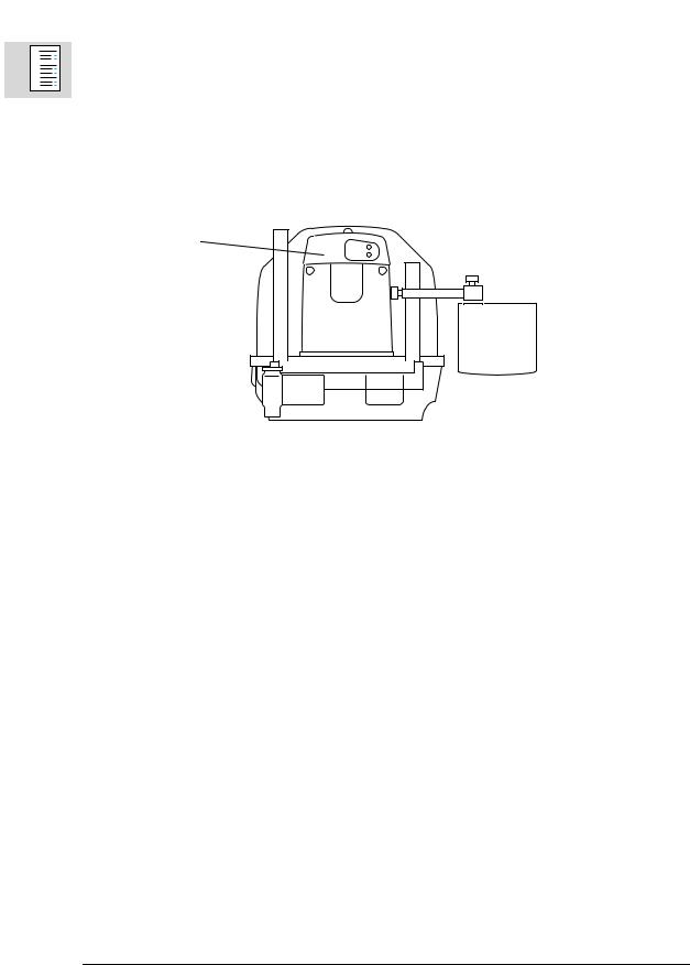
1.2Sensor unit
The sensor unit is mounted on two column elements. The sensor unit measures the environment inside the patient compartment.
The sensor unit contains the following subassemblies:
−Housing
−WT2 Sensor PCB
−O2 Sensor PCB
−Alarm PCB with alarm light
Sensor unit
Fig. 3: Left view of Caleo
The sensor unit contains the following sensors:
−Air-temperature sensors
−Oxygen sensor(s) (optional)
−Second oxygen sensor for oxygen regulation (optional)
−Humidity sensor (optional)
For internal use only. Copyright reserved.
F6150000T01.fm 08.02.01
6150.000 Caleo |
02/2001 |
Function Description |
Page 7 |

A
B
C
Dräger Medizintechnik |
|
|
|
1.2.1WT2 Sensor PCB
The WT2 Sensor PCB measures the air temperature, skin temperature, humidity, and oxygen. These values are transmitted to the microcontroller of the WT2 Actuator PCB.
The WT2 Sensor PCB has the following subassemblies:
− Measurement of the patient's skin temperature
−Measurement of the air temperature and independent excess temperature monitoring
−Communication, A/D conversion, and electrical isolation
For internal use only. Copyright reserved.
F6150000T01.fm 08.02.01
6150.000 Caleo |
02/2001 |
Function Description |
Page 8 |

Dräger Medizintechnik |
|
|
|
For internal use only. Copyright reserved.
F6150000T01.fm 08.02.01
A
B
C
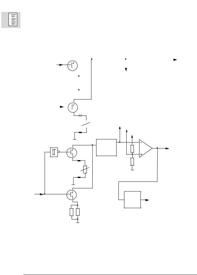
Measurement of the Skin Temperature
The control signals from the shift registers switch the individual skin-temperature measuring channels to the temperature hybrids. For the multiplexer to be able to test the skintemperature measuring channels, it switches a parallel resistor to the respective skintemperature measuring channel during operation.
The microcontroller of the WT2 Sensor PCB tests the accuracy of the temperature hybrids during the 10-minute test. To do so, a control signal is transmitted to a FET. Thus, the 36 °C resistor is switched to the input of the temperature hybrids.
Analog measured values to the temperature hybrids
Control signal
NTC
Control signal |
Control signals |
|
NTC
Multiplexer
Control signal
NTC
Control signal
Skin-temperature channels test
NTC
FET
Control signal
36 °C test
Fig. 4: Block diagram of the WT2 Sensor PCB, skin-temperature measurement
6150.000 Caleo |
02/2001 |
Function Description |
Page 9 |
Dräger Medizintechnik |
|
|
|
A
B
C
Measurement of the air temperature and independent excess temperature monitoring
The analog measured values of the air temperature reach temperature hybrid 1. The downstream excess-temperature comparator makes sure the air temperature in the patient compartment does not exceed 40.2 °C. If the air temperature is higher, a logic circuit on the WT2 Actuator PCB switches off the air heater.
During the 10-minute test, the excess-temperature test circuit simulates a temperature of 40.2 °C. During this period, the microcontroller monitors the function of the excesstemperature monitoring. An additional test circuit monitors also the air-temperature sensor 1.
For internal use only. Copyright reserved.
F6150000T01.fm 08.02.01
|
|
|
|
Temperature |
|
Analog |
|
|
|
|
hybrid 2 |
|
|
|
|
|
|
|
measured |
|
|
|
|
|
|
|
|
|
|
|
|
|
|
value |
|
|
|
|
|
|
|
|
To skin-temperature |
|
|
|
|
|
|
|||
Test circuit |
|
|
|
|
|
|
measurement |
|
|
|
|
|
|
|
|
||
|
|
|
|
|
|
|
|
|
|
|
|
|
|
|
|
|
|
|
|
|
|
|
|
|
|
|
|
|
|
|
|
|
|
|
|
|
|
|
|
|
|
|
|
|
|
|
|
|
|
|
|
|
|
|
|
|
|
|
|
|
|
|
Air-temperature |
|
Analog measured value |
sensor 1 |
|
|
|
Analog measured value |
|
|
|
|
|
|
Uref
|
|
|
Excess-temperature comparator |
|
Temperature |
|
To |
|
hybrid 1 |
|
|
|
|
microcontroller |
|
|
|
|
|
|
Air-temperature |
|
|
|
sensor 2 |
|
|
Control |
|
|
|
signal |
|
Optocoup |
Excess air-temperature |
|
|
ler |
|
|
|
(independent switch-off path) |
|
|
|
|
|
|
Excess-temperature |
|
|
|
test circuit |
|
|
Fig. 5: Block diagram of the WT2 Sensor PCB, air-temperature measurement and independent excess-temperature monitoring
6150.000 Caleo |
02/2001 |
Function Description |
Page 10 |
Dräger Medizintechnik |
|
|
|
|
|
|
|
|
|
|
|
|
Communication, A/D conversion, and electrical isolation |
|
|
|
|
|
|
|
|
|
The microcontroller controls and monitors the WT2 Sensor PCB functions. |
|
|
|
|
|
|
|
|
|
A quartz clocks the microcontroller (with integrated CAN/RS232 interface) with a frequency |
|
|
|
|
|
|
|
|
|
|
|
|
|
|
|
|
|
|
|
of 8 MHz. |
|
|
A |
|
|
|
|
|
|
|
|
|
|
|
|
|
|
|
|
|
|
|
|
|
|
|
|
|
|
|
|
|
B |
|
|
|
|
Shift registers use the SPI bus to control non-time-critical input and output connections. |
||
|
|
|
|
|
|||||
|
|
|
|
|
|
||||
|
|
C |
|
|
|
|
|||
|
|
|
|
The microcontroller has serial connections, input/output connections, interruptible |
|||||
|
|
|
|
|
|
||||
|
|
|
|
|
|
|
|
|
|
|
|
|
|
|
|
|
|
|
|
|
|
|
|
|
|
|
|
|
|
|
|
|
|
|
|
|
|
|
connections, and analog input connections for measurement. Optocouplers electrically |
|
|
|
|
|
|
|
|
|
isolate the input and output signals. The integrated RS232 interface of the microcontroller |
|
|
|
|
|
|
|
|
|
connects the WT2 Sensor PCB with the O2 Sensor PCB. The microcontroller can switch |
|
|
|
|
|
|
|
|
|
on/off the O2 Sensor PCB. |
|
|
|
|
|
|
|
|
|
The CAN bus driver connects the microcontroller with the WT2 Actuator PCB. |
|
|
|
|
|
|
|
|
|
The DC/DC converter generates the 5 VISO voltage from the 5 V operating voltage. |
|
|
|
|
|
|
|
|
|
An EEPROM stores board-specific data. A/D converter and EEPROM are controlled with the |
|
|
|
|
|
|
|
|
|
SPI bus. The A/D converter integrated in the microcontroller receives the signal from the |
|
|
|
|
|
|
|
|
|
independent excess-temperature monitoring. |
|
|
|
|
|
|
|
|
|
The A/D converter measures the analog measuring signals (humidity (optional feature), air |
|
|
|
|
|
|
|
|
|
temperature, skin temperature, and 5 VISO voltage). |
For internal use only. Copyright reserved.
F6150000T01.fm 08.02.01
6150.000 Caleo |
02/2001 |
Function Description |
Page 11 |

Dräger Medizintechnik |
|
|
|
A
B
C
For internal use only. Copyright reserved.
F6150000T01.fm 08.02.01
EEPROM
SPI bus |
Shift |
signals |
|
|
|||
register |
Control |
||
|
|||
|
|
|
|
|
Microcontroller |
|
|
|
|
|
Reset |
Optocou |
|
|
|
|
|
|
Sensor box |
pler |
|
|
|
signals |
|
CAN |
|
Optocou |
CAN RxD |
RS232 |
Shift |
|
|
|
|
|
|
|
|
||
bus |
CAN bus |
pler |
|
|
register |
Control |
|
CAN TxD |
CAN |
|
|
||||
|
driver |
Optocou |
|
|
|||
|
|
|
|
|
|
||
|
|
|
|
|
|
|
|
|
|
pler |
|
|
|
|
|
|
|
|
|
|
A/D converter |
|
|
|
|
Quartz |
|
A/D |
|
|
Analog |
|
|
|
|
converter |
|
measuring |
|
|
|
|
|
|
|
||
|
|
|
|
|
Output |
|
signals |
|
|
|
|
|
|
|
|
|
|
|
Excess |
|
|
|
|
|
|
|
temperature (Air) |
Addressing |
|
sensor |
|
|
|
|
|
|
|
5 VISO |
|
|
|
|
|
|
|
Humidity |
|
|
5 V |
|
5 VISO |
|
|
|
|
|
|
|
|
|
|
||
|
|
DC |
|
|
|
|
|
|
|
|
|
|
Optocou |
RxD |
|
|
|
|
|
|
pler |
||
|
|
DC |
|
|
(O2 Sensor PCB) |
||
|
|
|
|
|
|||
|
|
|
|
|
Optocou |
TxD |
|
|
|
|
|
|
pler |
||
|
|
|
|
|
|
(O2 Sensor PCB) |
|
|
Optocou |
ON/OFF |
|
pler |
|
|
(O2 Sensor PCB) |
|
|
|
|
Optocou |
O2 Sensor PCB |
|
pler |
|
|
||
|
|
|
|
|
|
Fig. 6: Block diagram of the WT2 Sensor PCB (communication, A/D conversion, and electrical isolation)
6150.000 Caleo |
02/2001 |
Function Description |
Page 12 |

Dräger Medizintechnik |
|
|
|
1.2.2O2 Sensor PCB
The O2 Sensor PCB receives the converted voltage from the oxygen sensor.
A
B
C
EEPROM |
|
|
|
|
9 |
|
|
Differential |
|
Sensor 1/2 |
Potentiostat |
|
|
|
|
|
amplifier |
|
|
1 |
|
Multipl |
|
|
|
|
|
||
|
|
|
|
|
|
|
exer |
|
|
2 |
|
|
|
|
10 |
URef |
|
|
|
|
|
|
|
|
|
Uabfang |
|
|
|
a |
|
Multipl |
|
|
|
Amplifier |
|
|
|
|
exer |
|
|
|
|
|
|
|
|
|
a |
b |
|
|
|
|
|
|
|
|
Amplifier |
|
|
|
I/U converter |
|
4.2 V |
|
|
|
|
|
Microcontro |
Channel 1 |
URef |
|
|
|
|
Multipl |
|
ller |
|
|
|
|
|
|
|
|
exer |
|
|
Channel 2 |
|
|
|
|
|
|
|
b |
EEPROM |
|
|
|
|
|
Fig. 7: Block diagram of the O2 Sensor PCB
For internal use only. Copyright reserved.
F6150000T01.fm 08.02.01
6150.000 Caleo |
02/2001 |
Function Description |
Page 13 |
 Loading...