


Technical Service Manual
Babylog 8000/8000SC/8000 plus
Intensive Care Ventilator
Revision 10.0 6173.3 9029623
Emergency Care • Perioperative Care • Critical Care • Perinatal Care • Home Care |
Because you care |
Copyright by Dräger Medical AG & Co. KGaA, Lübeck, Germany.
No reproduction allowed for commercial purposes.
Read and understand the Instructions for Use/Operator’s Manual.
This Technical Documentation does not replace the Instructions for Use/Operator’s Manual.
The warranty and liability conditions of the general terms and conditions for business transactions of Dräger Medical AG & Co. KGaA are not extended by this Technical Documentation.
Observe all applicable technical laws and regulations.
Insofar as reference is made to laws, regulations or standards, these are based on the legal system of the Federal Republic of Germany. Observe the laws and regulations applicable in your country.

Contents
General
1 |
Notes |
9 |
|
1.1 Symbols and Definitions ......................................................................................................... |
9 |
GBK61733XXIECIVZ.fm 18.05.05 |
All rights reserved. Copyright reserved. |
Function Description
1 |
General |
13 |
|
|
1.1 |
Ventilation Modes ................................................................................................................. |
13 |
|
1.2 |
Additional Functions ............................................................................................................. |
13 |
|
1.3 |
Monitoring ............................................................................................................................. |
13 |
2 |
Block Diagrams |
14 |
|
2.1Block Diagram of the Components in
Babylog 8000/Babylog 8000 SC with LC Display 14
2.2Block Diagram of the Components in
Babylog 8000/Babylog 8000 plus with EL Display 15
|
2.3 |
Block Diagram of the Babylog 8000/ Babylog 8000 plus/Babylog 8000 SC ........................ |
16 |
|
3 |
Airway Monitoring |
17 |
||
|
3.1 |
Airway Pressure ................................................................................................................... |
17 |
|
|
3.2 |
Trigger Signal ....................................................................................................................... |
17 |
|
|
3.3 |
Measurement of the Fraction of Inspired O2 ....................................................................... |
17 |
|
|
3.4 |
Patient Flow (Babylog 8000/Babylog 8000 plus) .................................................................. |
18 |
|
4 |
Monitoring Functions |
19 |
||
|
4.1 |
Fraction of inspired O2 (FiO2) ............................................................................................... |
19 |
|
|
|
4.1.1 |
O2 Measurement .................................................................................................... |
19 |
|
|
4.1.2 |
O2 Calibration ......................................................................................................... |
19 |
|
4.2 |
Gas Supplies ........................................................................................................................ |
20 |
|
|
4.3 |
Airway Pressure Monitoring ................................................................................................. |
20 |
|
|
4.4 |
Disconnect Monitoring .......................................................................................................... |
20 |
|
|
4.5 |
Overpressure and Low Pressure Alarms ............................................................................. |
21 |
|
Dräger Medical AG & Co. KGaA |
Contents |
I |

Contents
|
|
4.5.1 Babylog 8000 up to Software Version 3.0 ............................................................... |
|
21 |
|
|
|
4.5.2 |
Dynamic Stenosis Limit ........................................................................................... |
|
21 |
|
4.6 |
Minute Volume Monitoring (Babylog 8000/Babylog 8000 plus) ............................................ |
|
23 |
|
|
|
4.6.1 Babylog 8000 with Software Versions 2 and 3 ....................................................... |
|
23 |
|
|
|
4.6.2 Babylog 8000 Software with Version 4.0 or Higher ................................................ |
|
23 |
|
|
|
4.6.3 |
Babylog 8000 plus .................................................................................................. |
|
23 |
|
4.7 |
Audible Alarm Generator Monitoring .................................................................................... |
|
23 |
|
|
4.8 |
Operating Voltage Monitoring ............................................................................................... |
|
23 |
|
|
4.9 |
Rotary Potentiometer Monitoring .......................................................................................... |
|
23 |
|
|
4.10 |
ROM Test .............................................................................................................................. |
|
24 |
|
|
4.11 |
RAM Test .............................................................................................................................. |
|
24 |
|
|
4.12 |
Temperature Monitoring ........................................................................................................ |
|
24 |
|
|
4.13 |
Relay and Valve Monitoring .................................................................................................. |
|
24 |
|
|
4.14 |
Battery Monitoring ................................................................................................................ |
|
24 |
|
|
4.15 |
Flow Measurement Monitoring (Babylog 8000/ Babylog 8000 plus) .................................... |
24 |
||
5 |
Alarms, Cautions and Advisory Messages |
|
25 |
||
|
5.1 |
Message Display .................................................................................................................. |
|
25 |
|
|
5.2 |
Display and Menu ................................................................................................................. |
|
25 |
|
|
|
5.2.1 Babylog 8000/Babylog 8000 SC with LC Display ................................................... |
|
26 |
|
|
|
5.2.2 Babylog 8000/Babylog 8000 plus with EL Display .................................................. |
|
26 |
|
6 |
Function of the Control Elements |
|
27 |
||
|
6.1 |
Potentiometers (Rotary Knobs) ............................................................................................ |
|
27 |
|
|
|
6.1.1 Fraction of inspired O2 (O2 vol.%) .......................................................................... |
|
27 |
|
|
|
6.1.2 |
Inspiratory time (TI) ................................................................................................. |
|
27 |
|
|
6.1.3 |
Expiratory time (TE) ................................................................................................ |
|
27 |
|
|
6.1.4 Inspiratory flow (Insp. Flow) .................................................................................... |
|
27 |
|
|
|
6.1.5 Inspiratory pressure limit (Pinsp) ............................................................................. |
|
27 |
|
|
|
6.1.6 |
PEEP/CPAP ............................................................................................................ |
|
27 |
|
6.2 |
Keys |
...................................................................................................................................... |
|
28 |
|
|
|
|
||
II |
Dräger Medical AG & Co. KGaA |
Contents |
|
||
Copyright .reserved rights All |
GBK61733XXIECIVZ |
.reserved |
05.05.18 fm. |

GBK61733XXIECIVZ.fm 18.05.05 |
All rights reserved. Copyright reserved. |
|
|
|
|
Contents |
|
|
|
|
|
|
|
6.2.1 |
CPAP ...................................................................................................................... |
28 |
|
|
6.2.2 IPPV/IMV (CMV) (up to software version 4.n) ........................................................ |
28 |
|
|
|
6.2.3 |
Man. Insp. ............................................................................................................... |
28 |
|
|
6.2.4 |
2-min Silence .......................................................................................................... |
28 |
|
|
6.2.5 |
Reset/Check (OK) .................................................................................................. |
28 |
|
|
6.2.6 Backlight On/Off (Babylog 8000/8000 SC with LC Display) ................................... |
28 |
|
|
|
6.2.7 "Cal. Config." (as of software version 5.n) .............................................................. |
29 |
|
|
|
6.2.8 |
Keys ....................................................................................................................... |
29 |
7 |
Cold Start/Warm Start Behavior |
30 |
||
|
7.1 |
Cold-Start Behavior .............................................................................................................. |
30 |
|
|
7.2 |
Warm-Start Behavior ............................................................................................................ |
30 |
|
8 |
Description of Pneumatic Functions |
31 |
||
|
8.1 |
Gas Supplies ........................................................................................................................ |
31 |
|
|
8.2 |
Controlled Ventilation ........................................................................................................... |
32 |
|
|
|
8.2.1 |
Inspiration ............................................................................................................... |
32 |
|
|
8.2.2 |
Expiration ............................................................................................................... |
33 |
|
|
8.2.3 |
PEEP ...................................................................................................................... |
33 |
|
|
8.2.4 |
CPAP ...................................................................................................................... |
33 |
9 |
Measurement of the Ventilation Parameters |
34 |
||
|
9.1 |
O2 Measurement .................................................................................................................. |
34 |
|
|
9.2 |
Measurement of the Airway Pressure .................................................................................. |
34 |
|
|
9.3 |
Pneumatics Control PCB ...................................................................................................... |
35 |
|
|
9.4 |
Pneumatics Analog PCB ...................................................................................................... |
36 |
|
|
9.5 |
Patient System Heater ......................................................................................................... |
37 |
|
|
9.6 |
Pressure Sensor Base PCB ................................................................................................. |
37 |
|
|
9.7 |
O2 Amplifier PCB ................................................................................................................. |
37 |
|
10 |
Components of the Electronic Assembly |
38 |
||
|
10.1 |
Power Supply Unit ................................................................................................................ |
38 |
|
Dräger Medical AG & Co. KGaA |
Contents |
III |

Contents |
|
|
10.2 |
Motherboard PCB ................................................................................................................. |
38 |
10.3 |
CPU 68000 PCB ................................................................................................................... |
39 |
10.4 |
I/O PCB ................................................................................................................................ |
40 |
10.5 |
Flow PCB (Babylog 8000/Babylog 8000 plus) (optional) ...................................................... |
41 |
10.6 |
Monitoring PCB .................................................................................................................... |
42 |
|
10.6.1 Measurement of Analog Signals ............................................................................. |
42 |
|
10.6.2 Measurement of Digital Inputs ................................................................................ |
42 |
|
10.6.3 Measurement of Digital Outputs ............................................................................. |
42 |
10.7 |
Front Adapter PCB ............................................................................................................... |
45 |
10.8Front Controller PCB
(Babylog 8000/Babylog 8000 SC with LC Display) 46
10.9 |
Front PCB (Babylog 8000/Babylog 8000 plus with EL Display) ........................................... |
47 |
10.10Display PCB (Babylog 8000/Babylog 8000 SC with LC Display) ......................................... |
48 |
|
10.11 EL display (Babylog 8000/Babylog 8000 plus with EL Display) ........................................... |
49 |
|
10.12Potentiometer Field .............................................................................................................. |
50 |
|
10.13Display Field ......................................................................................................................... |
50 |
|
10.14Communication PCB ............................................................................................................ |
51 |
|
10.15Interface PCB ....................................................................................................................... |
52 |
|
11 Sensors |
53 |
|
11.1 |
Pressure Sensors ................................................................................................................. |
53 |
11.2 |
Y-Piece with Flow Sensor (Babylog 8000/Babylog 8000 plus) ............................................. |
53 |
|
11.2.1 Measuring Principle of the Flow Measuring Bridge ................................................ |
54 |
11.3 |
O2 Sensor ............................................................................................................................ |
55 |
Copyright .reserved rights All |
GBK61733XXIECIVZ |
.reserved |
05.05.18 fm. |
IV |
Dräger Medical AG & Co. KGaA |
Contents |

GBK61733XXIECIVZ.fm 18.05.05 |
All rights reserved. Copyright reserved. |
|
|
Contents |
Replacing Non Repairable Items |
|
|
1 |
Important Information |
59 |
2 |
Cleaning or Replacing the Cooling Air Filter Every 4 Weeks |
60 |
3 |
Replacing the O2 Sensor Capsule |
61 |
|
3.1 O2 Sensor Calibration ........................................................................................................... |
61 |
|
3.2 Calibrating the O2 Sensor After Replacement ...................................................................... |
61 |
|
3.3 Disposing of the O2 Sensor Capsule .................................................................................... |
63 |
4 |
Replacing the Lip Seals Every 2 Years |
64 |
5 |
Replacing the NiCd Battery (Power Failure Alarm) Every 2 Years |
65 |
6 |
Replacing the Pressure Reducer Every 6 Years |
67 |
Schematics and diagrams |
|
|
1 |
Schematics and Diagrams |
77 |
Error List |
|
|
1 |
Error messages |
91 |
2 |
List of device error messages |
92 |
Annex |
|
|
|
Spare parts list |
97 |
|
Test List |
97 |
|
Technical Information according to EMC standard IEC/EN 60601-1-2:2001 |
97 |
Dräger Medical AG & Co. KGaA |
Contents |
V |

Contents
Copyright .reserved rights All |
GBK61733XXIECIVZ |
.reserved |
05.05.18 fm. |
VI |
Dräger Medical AG & Co. KGaA |
Contents |

General
7

8
Babylog 8000 |
General |
|
|
|
|
1 |
Notes |
This Technical Documentation/Service Manual conforms to the International |
|
|
Standard IEC 60601-1. |
|
|
Read each step in every procedure thoroughly before beginning any test. |
|
|
Always use the proper tools and specified test equipment. If you deviate from |
|
|
the instructions and/or recommendations in this Technical Documenta- |
|
|
tion/Service Manual, the equipment may operate improperly or unsafely, or |
|
|
the equipment could be damaged. |
|
|
Use only original Dräger parts and supplies. |
|
|
The maintenance procedures described in this Technical Documenta- |
|
|
tion/Service Manual may be performed by qualified service personnel only. |
|
|
These maintenance procedures do not replace inspections and servicing by |
|
|
Dräger Medical AG & Co. KGaA. |
|
|
|
|
|
Strictly follow the Instructions for Use/Operating Instructions! This |
|
|
Technical Documentation does not replace the Instructions for |
|
|
Use/Operating Instructions. Any use of the product requires full |
|
|
understanding and strict observation of the product-specific Instruc- |
|
|
tions for Use/Operating Instructions. |
|
|
|
|
|
|
|
|
Unless otherwise stated, reference is made to laws, regulations or stan- |
|
|
dards (as amended) applicable in the Federal Republic of Germany. |
1.1 |
Symbols and Defini- |
|
|
||
|
tions |
|
This symbol indicates a warning.
Released Printed on 18.05.05 GBK61733XXA01.fm |
reserved. Copyright reserved. |
Version 1.0_ |
All rights |
This symbol indicates tips and useful information.
This symbol is used to alert against unsafe practices when handling electrostatic sensitive devices (ESD).
Definitions according to German standard DIN 31051:
Inspection |
= examination of actual condition |
|
Maintenance |
= measures to maintain specified condition |
|
Repair |
= |
measures to restore specified condition |
Servicing |
= |
inspection, maintenance, and repair |
Dräger Medical AG & Co. KGaA |
6173.3 |
9 |

General |
Babylog 8000 |
|
|
reserved. Copyright reserved. |
Released Printed on 18.05.05 GBK61733XXA01.fm |
All rights |
Version 1.0 |
10 |
Dräger Medical AG & Co. KGaA |
6173.3 |

Function Description
11

12

Printed on 18.05.05 F61733XXT01.fm |
All rights reserved. Copyright reserved. |
Function description |
Babylog 8000 |
|
|
1General
Babylog 8000/Babylog 8000 plus has a flow measurement function. The Babylog 8000 SC can be upgraded to a Babylog 8000 using the "flow measurement conversion kit.
1.1Ventilation Modes
Babylog 8000/Babylog 8000 plus/8000 SC provides the following ventilation modes:
IPPV (Intermittent Positive Pressure Ventilation), controlled and assisted constant-volume ventilation
SIPPV (Synchronized Intermittent Positive Pressure Ventilation), synchronized controlled and assisted constant-volume ventilation
IMV (Intermittent Mandatory Ventilation)
SIMV (Synchronized Intermittent Mandatory Ventilation) weaning method for spontaneously breathing patients
CPAP (Continuous Positive Airway Pressure) spontaneous breathing with positive airway pressure
PSV (Pressure Support Ventilation) (optional as of software version 5.n)
1.2Additional Functions
Babylog 8000/Babylog 8000 plus/8000 SC provides the following (optional) additional functions:
High-frequency ventilation (HV) (as of software version 4.n)
Volume guarantee (VG) (as of software version 5.n)
1.3Monitoring
Babylog 8000/Babylog 8000 plus/8000 SC has integrated monitoring functions for:
Fraction of inspired O2 (FiO2)
Airway pressure (Paw)
Flow ( ) (Babylog 8000/Babylog 8000 plus)
Minute volume (MV)
Tidal volume (VT)
Dräger Medical AG & Co. KGaA |
6173.3 |
13 |
Function description
2Block Diagrams
2.1Block Diagram of the Components in
Babylog 8000/Babylog 8000 SC with LC Display
Elektronic unit
|
|
|
|
|
|
|
|
|
|
|
|
|
|
|
Loud speaker |
|
|
|
|
|
|
|
|
|
|
|
|
|
|
|
|
|
|
|
|
|
|
|
|
|
|
|
|
|
|
|
|
Battery |
|
|
|
|
|
|
connector |
|
|
|
|
|
|
|
|
|
|
|
|
|
|
|
|
|
|
|
||
|
|
Fan |
|
|
|
|
|
|||
|
|
|
|
|
|
|
|
|
||
|
|
|
|
|
|
|
|
|
|
|
Flow |
|
|
RS232 PCB |
|
|
|
|
|
||
|
|
|
|
|
|
|
|
|
||
|
|
CPU 68000 PCB |
|
|
MutterboardLP |
|
|
|||
|
|
|
|
|
|
|
|
|
||
Watch dog PCB |
|
|
Monitoring PCB |
|
|
|
|
|||
|
|
Communication PCB |
|
|
|
|
|
|||
|
|
|
|
|
|
|
|
|
|
|
|
|
|
|
|
|
|
|
|
|
|
|
|
Flow PCB (not 8000SC) |
|
|
|
|
||||
|
|
|
|
|
|
|
|
|
|
|
|
|
|
|
|
|
|
|
|
|
|
|
|
I/O PCB |
|
|
|
|
|
|||
|
|
|
|
|
|
|
|
|
|
|
|
|
|
|
|
|
|
|
|
|
|
|
|
Power supply PCB |
|
|
|
|
|
|||
|
|
|
|
|
|
|
|
|
|
|
cord |
|
|
|
|
|
|
|
|
|
|
|
|
|
|
|
|
|
|
|
||
Power |
|
|
|
Frontadapter PCB |
||||||
|
|
|
|
|
||||||
|
|
|
|
|
|
|
|
|
||
|
|
|
|
|
|
|
|
|
|
|
|
|
|
|
|
Frontcontroller |
PCB |
||||
|
|
|
|
|
|
|
|
|
|
|
|
|
|
|
|
|
|
|
|
|
|
|
|
|
|
Front |
Monitoringfield |
|
PCBDisplay |
|
Potentiometerfield |
|
|
|
|
|
|
|
|
|
|
||
|
|
|
|
|
|
|
|
|
|
|
pressure AIR pressure O2 Pinsp Pexsp |
|
|
|
|
Vol.% O2 |
|||||
|
|
|
|
|
|
|
|
|
|
|
|
|
|
|
|
|
|
|
|
|
|
|
|
Pressure sensor PCB |
|
|
|
|
|
|
||
|
|
|
O2 ampilfier |
|
|
|
O2 sensor |
|||
|
|
|
|
|
|
|
|
|||
|
|
|
|
|
|
|
|
|||
|
|
|
|
|
|
|
|
|
|
|
|
Pneumatic Analog |
|
|
|
|
|
|
|
|
|
|
PCB |
|
|
|
Patiententeil- |
heating |
|
|||
|
|
|
|
|
|
|
|
|||
|
Pneumatic |
driver PCB |
|
|
|
PEEP/PIP |
|
|
|
|
|
|
|
|
|
|
|
|
|||
|
|
|
|
|
|
|
|
|||
|
|
|
Valves |
|
||||||
|
|
|
|
|
|
|||||
|
|
|
|
|
|
|
|
|
|
|
Pneumatic unit
LC display
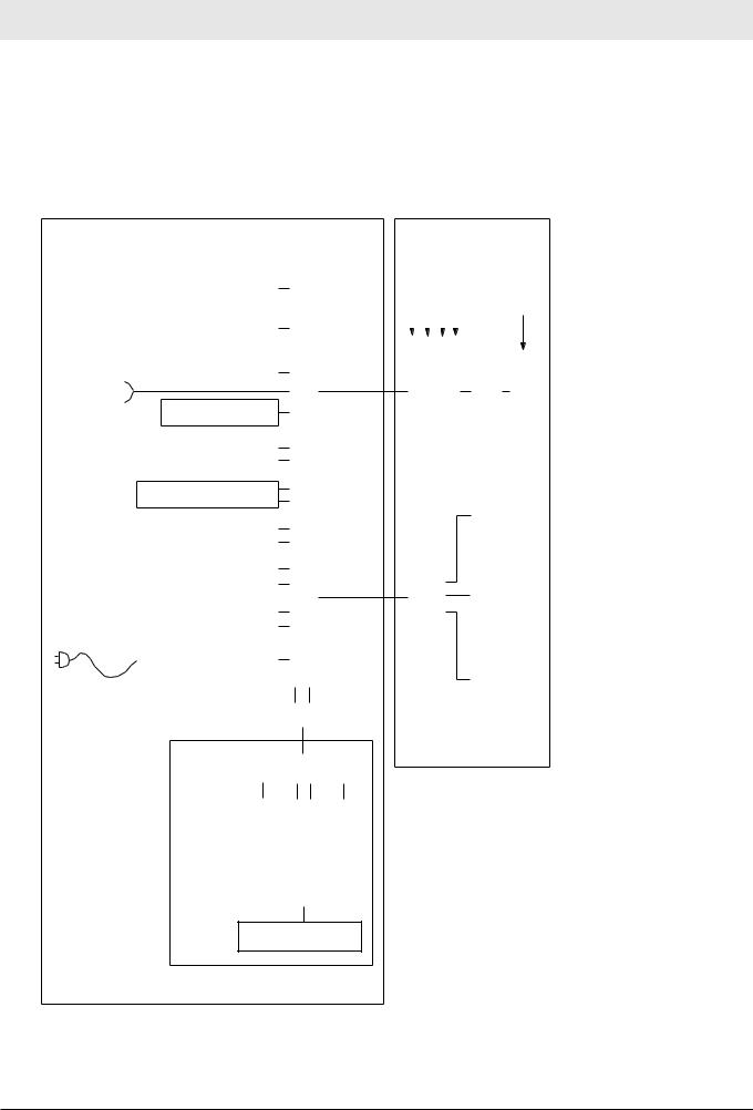
Fig. 1: Block diagram of the Babylog 8000/8000 SC with LC display
14 |
Dräger Medical AG & Co. KGaA |
6173.3 |
Babylog 8000
All rights reserved. Copyright reserved. |
Printed on 18.05.05 F61733XXT01.fm |
Function description |
Babylog 8000 |
|
|
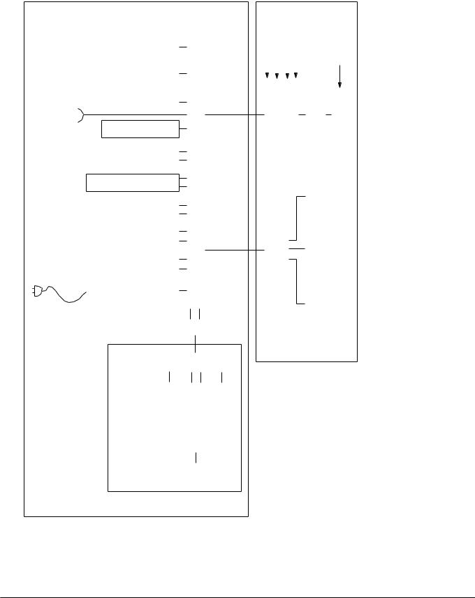
2.2Block Diagram of the Components in
Babylog 8000/Babylog 8000 plus with EL Display
Printed on 18.05.05 F61733XXT01.fm |
All rights reserved. Copyright reserved. |
Elektronic unit
|
|
|
|
|
|
|
|
|
|
|
|
|
|
|
|
|
|
|
Loud speaker |
|
|
|
|
|
|
|
|
||
|
|
|
|
|
|
|
|
|
|
|
|
|
||
|
|
|
|
|
|
|
|
|
|
|
|
|
||
|
|
|
|
Battery |
|
|
|
|
|
|
|
|
||
connector |
|
|
|
|
|
|
|
|
|
|
|
|
|
|
|
|
|
|
|
|
|
|
|
|
|
|
|
||
|
|
Fan |
|
|
|
|
|
|
|
|
||||
|
|
|
|
|
|
|
|
|
|
|
|
|||
|
|
|
|
|
|
|
|
|
|
|
|
|
||
Flow |
|
|
RS232 PCB |
|
|
|
|
|
|
|
|
|||
|
|
|
|
|
|
|
|
|
|
|
|
|
||
|
|
CPU 68000 PCB |
|
|
|
|
|
|
|
|
||||
|
|
|
|
|
|
|
MutterboardLP |
|
|
|||||
Watch dog PCB |
|
|
Monitoring PCB |
|
|
|
|
|||||||
|
|
Ccommunication PCB |
|
|
|
|
|
|||||||
|
|
|
|
|
|
|
|
|
|
|
|
|
|
|
|
|
|
|
|
|
|
|
|
|
|
|
|
|
|
|
|
Flow PCB |
|
|
|
|
|
|
|
|
||||
|
|
|
|
|
|
|
|
|
|
|
|
|
||
|
|
|
|
|
|
|
|
|
|
|
|
|
|
|
|
|
I/O PCB |
|
|
|
|
|
|
|
|
||||
|
|
|
|
|
|
|
|
|
|
|
|
|
||
|
|
|
|
|
|
|
|
|
|
|
|
|
|
|
|
|
Power supply PCB |
|
|
|
|
|
|
|
|
||||
|
|
|
|
|
|
|
|
|
|
|
|
|
|
|
cord |
|
|
|
|
|
|
|
|
|
|
|
|
|
|
|
|
|
|
|
|
|
|
|
|
|
|
|
||
Power |
|
|
|
|
|
Frontadapter PCB |
|
|||||||
|
|
|
|
|
|
|
|
|||||||
|
|
|
|
|
|
|
|
|
|
|
|
|||
|
|
|
|
|
|
|
|
|
|
|
|
|
|
|
|
|
|
|
|
|
|
Front PCB |
|
||||||
|
|
|
|
|
|
|
|
|
|
|
|
|
|
|
|
|
|
|
|
|
|
|
|
|
|
|
|
|
|
|
|
|
|
Front |
|
Monitoringfield |
|
|
converterELD |
|
|
Potentiometerfield |
||
|
|
|
|
|
|
|
|
|
|
|
|
|||
|
|
|
|
|
|
|
|
|
|
|
|
|
|
|
|
|
|
|
|
|
|
|
|
|
|
|
|
|
|
|
|
|
|
|
|
|
EL display |
|
|
|
|
|||
|
|
|
|
|
|
|
|
|
|
|
|
|
|
|
pressure AIR pressure O2 Pinsp Pexsp |
|
|
|
|
Vol.% O2 |
||||||
|
|
|
|
|
|
|
|
|
|
|
|
|
|
|
|
|
|
|
|
|
|
|
|
|
|
Pressure sensor PCB |
|
|
|
|
|
|
|||
|
|
|
O2 amplifier |
|
|
|
O2 sensor |
||||
|
|
|
|
|
|
|
|
||||
|
|
|
|
|
|
|
|
||||
|
|
|
|
|
|
|
|
|
|
|
|
|
|
|
|
|
|
|
|
|
|
|
|
|
Pneumatic |
Analog PCB |
|
|
|
Patient unit |
heating |
|
|||
|
|
|
|
|
|
|
|
||||
|
amplifier |
|
|
|
|
|
PEEP/PIP |
|
|
|
|
|
Pneumatic |
PCB |
|
|
|
|
|
|
|
|
|
|
|
|
|
|
|
|
|
|
|||
|
|
|
|
Valves |
|
||||||
|
|
|
|
|
|
|
|||||
|
|
|
|
|
|
|
|
|
|
|
|
Pneumatic unit
Fig. 2: Block diagram of the Babylog 8000/Babylog 8000 plus with EL display
Dräger Medical AG & Co. KGaA |
6173.3 |
15 |
Function description |
Babylog 8000 |
|
|
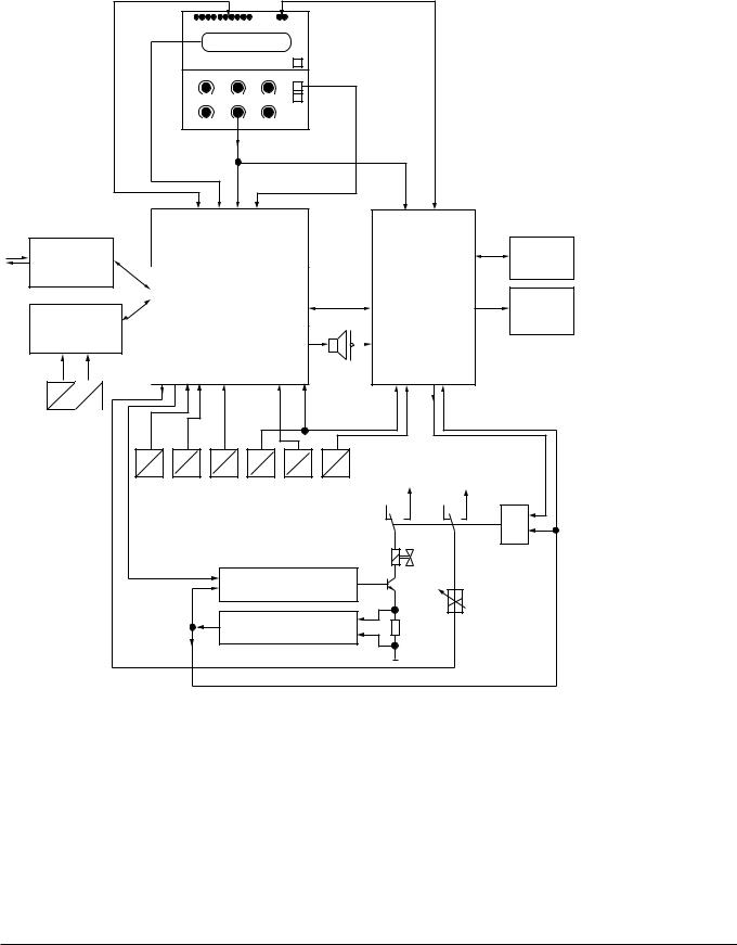
2.3Block Diagram of the Babylog 8000/ Babylog 8000 plus/Babylog 8000 SC
|
|
LEDs |
|
|
2 red Alarm LEDs |
|
||
|
|
8000/ |
Babylog8000 plus) |
|
|
|
|
|
|
LC display |
displayEL (Babylog |
|
Potentiometer |
|
|||
|
|
|
|
|
|
|||
|
|
|
|
|
|
keys |
|
|
|
|
|
|
Front |
|
|
|
|
Communication |
|
|
|
|
|
|
Battery |
|
|
|
|
|
|
|
|
|
|
|
|
|
CPU (Master) |
|
Monitoring |
Reserve |
||
Flow |
|
|
|
|
|
|
|
horn |
|
|
|
|
|
|
|
|
|
Babylog 8000 |
|
|
|
|
|
|
|
|
Babylog 8000 plus |
|
|
|
|
|
|
|
|
|
|
|
|
I/O |
|
|
|
|
E |
E |
|
|
|
|
|
|
|
V |
V |
|
|
|
|
|
|
|
Flow sensor |
|
|
|
|
|
|
|
|
|
E |
|
E |
E |
E |
E |
E |
|
|
|
P |
P |
P |
P |
O |
O |
|
|
PAIR |
PO2 |
Pexsp |
Pinsp |
|
+27 V |
+5 V |
|
|
O2-Sensor |
|
||||||
|
|
|
|
|
|
|
|
& |
|
|
|
|
|
|
|
24 Ventile |
|
|
|
|
|
Valve amplifier |
|
|
||
|
|
|
|
|
|
|
|
PEEP/PIP valve |
|
|
|
|
Valve monitoring |
|
|
||
Fig. 3: Block Diagram of the Babylog 8000/Babylog 8000 plus/Babylog 8000 SC
All rights reserved. Copyright reserved. |
Printed on 18.05.05 F61733XXT01.fm |
16 |
Dräger Medical AG & Co. KGaA |
6173.3 |

Printed on 18.05.05 F61733XXT01.fm |
All rights reserved. Copyright reserved. |
Function description |
Babylog 8000 |
|
|
3Airway Monitoring
In the ventilation modes IPPV/IMV and CPAP, the airway pressure (Paw), the flow at the Y-piece VT (Babylog 8000/Babylog 8000 plus), and the fraction of inspired O2 (FiO2) are measured.
Depending on the selected mode and the menu settings, the parameters are monitored and displayed on the screen. Pressure and flow curves as well as their storage can be displayed graphically on the LC display or EL display. In all ventilation modes, the chronological sequence of the airway pressure (Paw) is displayed in the LED bargraph.
3.1Airway Pressure
Two internal pressure sensors measure the pressure at the inspiratory outlet (Pinsp) and the pressure at the expiratory inlet (Pexp). The airway pressure is calculated as follows:
Paw = Pinsp – 0.7 (Pinsp – Pexp)
The following pressures are calculated from the Paw pressure signal:
Peak pressure (Peak)
Mean airway pressure (Pmean)
Positive end-expiratory pressure (PEEP)
The peak pressure is the maximum positive pressure of the most recent respiratory cycle. After 30 s, at the latest, a new respiratory cycle must be recognized and a new measured value for the peak pressure must be generated, otherwise the current measured value is no longer valid and is removed from the display.
The mean airway pressure is the initial value of a software digital filter.
The PEEP is either the pressure value during the expiratory phase at a zero expiratory flow or the last measured value before the next inspiration. Like the peak pressure, the PEEP is no longer valid after 30 s and is removed from the display if a new measured value is not generated within the 30-s period.
3.2Trigger Signal
In order to generate a trigger signal, the inspiratory flow must be integrated during spontaneous breathing and compared to the adjustable trigger threshold.
3.3Measurement of the Fraction of Inspired O2
A O2 sensor in the inspiration line measures the O2 content of the respiratory gas.
Calibration data of the O2 sensor is maintained after switching off the Babylog. If the Babylog has been out of operation for more than 24 hours, a calibration will automatically be carried out upon power-on.
The operator may also initiate a calibration manually, e.g. as required after replacing an O2 sensor.
Dräger Medical AG & Co. KGaA |
6173.3 |
17 |

Function description |
Babylog 8000 |
|
|
A two-step calibration with 21% and 100% O2 is always carried out in order to achieve a higher measurement accuracy over the whole concentration range and/or to be able to recognize a spent sensor cell.
The calibration procedure is described under section "4 Monitoring Functions".
If the O2 measurement fails, the Babylog generates an alarm. This alarm status is shown in the status field of the screen by the flashing indication "FiO2".
3.4Patient Flow (Babylog 8000/Babylog 8000 plus)
A direction-sensitive hot-wire flowmeter integrated into the Y-piece measures the inspiratory and expiratory flows through the tube. This measurement function must be reactivated each time after switching on Babylog 8000/Babylog 8000 plus and after each replacement of the sensor by calibrating the sensor. The flow signal is used to calculate the following values:
Tidal volume (VT)
Minute volume (MV)
Percentage of the MV uptake through spontaneous breathing
Tube leakage
The tidal volume is the expiratory flow signal applied between two breathing phase cycles.
Unlike the tidal volume, the minute volume is not related to a respiratory cycle. In the same way the inspiratory MV is calculated for leak rate detection. The expiratory minute volume is displayed. In addition to the complete minute volume, Babylog also calculates the expiratory minute volume uptake through spontaneous breathing.
Babylog calculates the percentage by comparing the total minute volume and the minute volume uptake through spontaneous breathing:
spont. = (MVspontaneous/MV) * 100%
The leakage at the tube can be estimated by comparing the inspiratory and the expiratory minute volume.
The leakage at the tube L is calculated as follows:
L= (MVinsp _ MVexp)/(MVinsp + MVexp) * 100.
The respiratory rate f is measured through the inspiratory respiratory phase cycles.
All measured values derived from the patient flow become valid only after successful calibration of the flow sensor.
If the flow sensor or the measuring electronics fails, an alarm is generated. However, Babylog can still be used without the functions depending on the flow measurement. This alarm status is shown in the status field of the screen by the flashing indication "flow".
18 |
Dräger Medical AG & Co. KGaA |
6173.3 |
All rights reserved. Copyright reserved. |
Printed on 18.05.05 F61733XXT01.fm |
Printed on 18.05.05 F61733XXT01.fm |
All rights reserved. Copyright reserved. |
Function description |
Babylog 8000 |
|
|
4Monitoring Functions
The system checks whether limit values are kept and all functions are ok. If a function fails or if the limit values are not met, Babylog will generate an alarm.
4.1Fraction of inspired O2 (FiO2)
4.1.1O2 Measurement
The measured O2 value is checked against upper and lower limit values. The alarm limits are automatically set at ±4 vol.% below the set FiO2value. A time delay makes sure no alarm is activated when the set value (O2) is changed or when the O2 sensor is calibrated.
The absolute sensor voltages are checked. The differential voltage between the two sensor cells must be lower than (U1 + U2)/8 +1 mV. The output voltage of each individual cell must be between 9.5 mV and 123.6 mV.
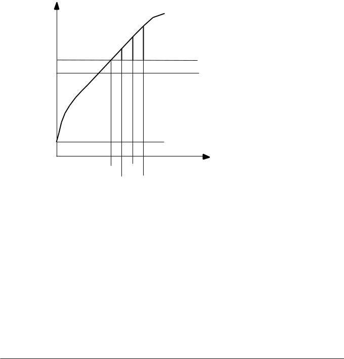
4.1.2O2 Calibration
The O2 sensor is either automatically calibrated 24 hours after the last calibration or manually after selection from the mode menu.
If the O2 sensor is replaced during operation the new O2 sensor will be calibrated automatically. However, Babylog cannot detect a sensor replacement if the unit is switched off. In this particular case, the operator has to calibrate the new O2 sensor manually.
By switching over a valve the sensor is separated from the respiratory gas flow and purged with the calibration gas (O2). This leads to a change in concentration at the O2 sensor. This change in concentration allows the Babylog to recognize the activation of the calibration valve.
The calibration valve is deactivated as soon as the calibration is completed.
A two-step calibration with 21% O2 and 100% O2 is carried out in order to achieve a higher measurement accuracy over the whole concentration range and to be able to recognize a spent sensor cell.
During the calibration procedure the microprocessor system processes (synchronizes) one of the two O2 sensor channels. The O2 channels are then submitted to a specific sequence of states controlled by one of the microprocessor systems and monitored for correct sequence and maximum period by the other. For instance, searching of the calibration values for 21% or 100% must not last longer than 3.5 minutes each.
The calibration value for 21% must be between 9.2 mV and 26 mV, and for 100% between 43.6 mV and 123.6 mV; this applies to both channels. The zero voltage resulting from both values must be between –6 mV and +6 mV.
After calibration is completed, the software checks whether the limit values respond correctly.
Calibration stops if a control gas fails.
Dräger Medical AG & Co. KGaA |
6173.3 |
19 |
Function description |
Babylog 8000 |
|
|
4.2Gas Supplies
The current measured values of the O2 and AIR gas supplies are considered when the valve bank is adjusted. The inlet pressure for O2 and AIR is 1.7 bar.
If the pressure falls below the limit value, a visible and audible alarm is generated. The operator is informed about the cause of the alarm by a plain text message on the display. If the adjusted O2 concentration is 21% or 100%, only an advisory message (no alarm) is displayed if the non-added gas type fails.
If the pressure exceeds the limit value, the safety venting mechanism is activated and the continuous flow is switched off. The Babylog will continue to operate only when the pressure has decreased to a permissible level.
If the AIR supply fails, the Babylog control switches to O2 supply. If the O2 supply fails, Babylog switches to AIR supply.
4.3Airway Pressure Monitoring
Depending on the selected mode and parameter settings, a certain airway pressure time profile is set. If the actual profile deviates from the set profile, the Babylog generates an alarm.
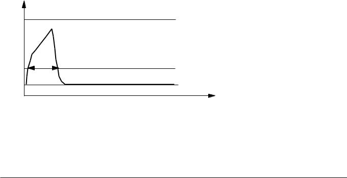
4.4Disconnect Monitoring
Babylog recognizes whether or not the hose system has been connected correctly. If the hose system has been connected incorrectly, the continuous flow is (partly) directed to atmosphere. No pressure builds up in the hose system. Babylog checks during each breathing cycle whether a sufficiently high pressure is available during inspiration. Since inspiratory breaths occur in the mandatory ventilation modes IPPV/IMV, SIPPV and SIMV, this monitoring does not function in the CPAP mode.
Paw |
Pinsp |
Tdis |
Pdis |
PEEP |
time |
Zeit |
Tdis > 25 ms ! |
Pdis = Pinsp - PEEP + PEEP
4
Fig. 4: Disconnect Monitoring
20 |
Dräger Medical AG & Co. KGaA |
6173.3 |
All rights reserved. Copyright reserved. |
Printed on 18.05.05 F61733XXT01.fm |

Function description |
Babylog 8000 |
|
|
During each mandatory breath, the level of the disconnection pressure (Pdis) must be exceeded without interruption for at least the disconnection time (Tdis), otherwise an alarm will be generated. Pdis is a function of the settings Pinsp and PEEP. If Pinsp is set considerably higher than the actually attained pressure, the Pdis alarm level likewise increases.
Depending on the flow and the inspiration time settings, the level might not be attained any more. Babylog 8000 generates an alarm even if there is no leakage in the breathing system.
4.5Overpressure and Low Pressure Alarms
During the inspiratory and expiratory phases, the airway pressure (Paw) must not exceed the set pressure limit by more than 10 mbar. If the set pressure limit is exceeded by 10 mbar to 20 mbar, Babylog generates an alarm and, at the same time, reduces the inspiratory breath time. The remaining time is added to the CPAP phase. If the set pressure limit is exceeded by more than 20 mbar, an alarm is activated and the breathing system is vented.
In the CPAP phase, the airway pressure must be r4 mbar of the set PEEP/CPAP. Otherwise an alarm will be generated. If the limit is exceeded by more than 10 mbar, venting is carried out as during the inspiratory phase even if the pressure falls below the absolute level of —2 mbar.
These overpressure and low pressure alarms apply to all ventilation modes.
4.5.1Babylog 8000 up to Software Version 3.0
|
Paw |
|
|
|
|
|
|
|
Stenose 2 (Notentlüftung) |
|
|
|
|
10 mbar |
|
|
|
|
|
|
Stenose 1 (Inspiration |
Exspiration) |
|
|
|
10 mbar |
|
|
|
|
Pinsp |
|
|
|
|
|
|
|
6 mbar |
Entlüftung |
|
|
|
|
|
|
|
|
PEEP |
4 mbar |
|
|
|
|
4 mbar |
|
|
||
|
|
|
|
|
|
Printed on 18.05.05 F61733XXT01.fm |
|
|
-2 mbar |
Zeit |
time |
|
|
|
|
||
Fig. |
5: Alarms |
|
|
|
|
4.5.2 |
Dynamic Stenosis Limit |
|
|
||
The dynamic stenosis limit applies to Babylog 8000 units with software version 4.0 and Babylog 8000 SC |
|||||
CopyrightAllreserved.reserved.rights |
|
|
|
|
|
|
Dräger Medical AG & Co. KGaA |
6173.3 |
|
21 |
|
Function description |
Babylog 8000 |
|
|
units with software version 1.0.
The limit value is (Pinsp + 5 mbar).
If this limit value is exceeded, the microprocessor system reads in the actual measured value at 8.3-ms intervals (sampling frequency). The limit value (Pinsp + 5 mbar) is subtracted from each of the actual measured values and entered in a summer.
As soon as the sum of 40 mbar (stenosis 1) is reached, Babylog switches over from inspiratory phase to expiratory phase. If a sum of 70 mbar is reached, despite of the safety measure (stenosis 1), the system will carry out an emergency venting.
Paw |
|
|
|
|
Σ = 40 mbar Stenose 1 |
|
|
Σ = 70 mbar Stenose 2 |
Pinsp + 5 mbar |
|
|
Pinsp |
|
|
PEEP |
|
|
|
|
time |
8,3 |
8,3 |
Zeit |
|
||
|
8,3 ms |
|
Fig. 6: Dynamic stenosis limit
All rights reserved. Copyright reserved. |
Printed on 18.05.05 F61733XXT01.fm |
22 |
Dräger Medical AG & Co. KGaA |
6173.3 |

Printed on 18.05.05 F61733XXT01.fm |
All rights reserved. Copyright reserved. |
Function description |
Babylog 8000 |
|
|
4.6Minute Volume Monitoring (Babylog 8000/Babylog 8000 plus)
The abbreviation MV (for minute volume) is used in the following text.
4.6.1Babylog 8000 with Software Versions 2 and 3
The monitoring menu is used to set the upper and lower alarm limits in the range of 0.03 L/min to
15 L/min. The upper and lower alarm limits are continuously compared with the measured MV value. If the value exceeds the upper alarm limits or falls below the lower alarm limit, the system will activate an alarm. Monitoring is deactivated during calibration of the flow sensor (Babylog 8000) to allow the measured MV value to stabilize. If the flow measurement system fails, the MV monitoring becomes ineffective.
4.6.2Babylog 8000 Software with Version 4.0 or Higher
The monitoring menu is used to set the upper and lower alarm limits in the range of 0.00 L/min to
15 L/min. The upper and lower alarm limits are continuously compared with the measured MV value. If the value exceeds the upper alarm limits or falls below the lower alarm limit, the system will activate an alarm. Monitoring is deactivated during calibration of the flow sensor (Babylog 8000) to allow the measured MV value to stabilize. If the flow measurement system fails, the MV monitoring becomes ineffective.
4.6.3Babylog 8000 plus
Babylog 8000 plus has the software 5.n.
4.7Audible Alarm Generator Monitoring
Babylog has two audible alarm generators (loudspeaker and piezo). During normal operation, the loudspeaker is the audio interface to the operator in the event of alarms. The piezo is only used in the event of power or loudspeaker failure.
At the end of the self-test, the loudspeaker is triggered with a test signal. This test signal is monitored with a microphone. If there is no feedback, Babylog generates error 817.
4.8Operating Voltage Monitoring
During operation, Babylog uses comparators to continuously monitors whether the operating voltages are within specified limits.
When Babylog is switched on, these comparators are checked by a defined changing of the comparator reference voltage.
4.9Rotary Potentiometer Monitoring
Input via rotary potentiometers are processed by two channels. Two microprocessor systems read the input via independent channels and compare the results.
Dräger Medical AG & Co. KGaA |
6173.3 |
23 |

Function description |
Babylog 8000 |
|
|
4.10ROM Test
During operation, the ROM area used is summed up per byte in a long word variable (long word = 32 bits) which is compared to the check sum stored in the ROM. If the check sums do not match, an error message will be displayed.
4.11RAM Test
During operation the RAM area used is tested with a simple algorithm. By writing 55 hex or AAhex in each cell every bit is checked for settability and resettability.
4.12Temperature Monitoring
A temperature sensor measures the internal temperature of the Babylog. If the temperature is not within the range of –20 °C to 75 °C, an alarm will be generated. If the temperature is too high, a message will inform the operator about a possible failure of the fan.
4.13Relay and Valve Monitoring
An excess-current monitoring function is integrated into the trigger electronics of the valves. The excesscurrent monitoring function is tested after switching on Babylog. If a valve is switched on and operated with the operate voltage for an excessive period of time, the excess-current monitoring function responds within a specific time.
The relay which enables de-energizing of the whole pneumatics assembly is also tested once after poweron. For this purpose, the relay is switched on and off once and the voltages at the relay contact are measured.
During operation, the system checks whether the voltage at the relay contact corresponds to the switching condition.
4.14Battery Monitoring
Babylog has a rechargeable Nicd battery for power failure alarms.
The battery is recharged automatically during operation and its charge checked periodically.
An error message is displayed if the voltage is too high or too low.
4.15Flow Measurement Monitoring (Babylog 8000/ Babylog 8000 plus)
During operation, the flow sensor is checked for correct functioning, freedom of damage and intact contacts.
24 |
Dräger Medical AG & Co. KGaA |
6173.3 |
All rights reserved. Copyright reserved. |
Printed on 18.05.05 F61733XXT01.fm |

Function description |
Babylog 8000 |
|
|
5Alarms, Cautions and Advisory Messages
The alarm structure of the Babylog has three priority levels:
Alarm |
- |
Immediate action required. |
|
|
|
Caution |
- |
Checking required. |
|
|
|
Advisory |
- |
Information for the operator. |
|
|
|
The priority level is indicated by the different tone sequences of the individual audible alarm.
5.1Message Display
When an alarm occurs the corresponding message is displayed as plain text message in a window of the display. The message can be canceled momentarily by pressing the Reset/Check key (or OK key as of software version 5.n). After a certain time out, the message appears again if its cause still exists.
If several alarms have occurred simultaneously, the highest-level alarm is shown on the display. Other alarms will be queued. A message whose cause no longer exist will not be displayed any more.
5.2Display and Menu
The display shows parameters and text messages. The functions of Babylog are set with keys and potentiometers.
The screen is separated into different areas:
Printed on 18.05.05 F61733XXT01.fm |
All rights reserved. Copyright reserved. |
|
|
|
|
Measurement |
Status field |
|
|
Grafic field |
|
||
|
|
|
|
field |
|
|
|
|
|
|
|
|
|
|
|
|
|
Menü line
Fig. 7: Screen display structure
The graphics field displays real-time curves.
The measured-value field displays monitoring parameter in digital representation.
The status field displays the operating mode and other status information.
The menu line displays the current function of the keys below the screen.
In some cases, the graphics and measured-value fields are combined to form one large field.
Dräger Medical AG & Co. KGaA |
6173.3 |
25 |

Function description |
Babylog 8000 |
|
|
5.2.1Babylog 8000/Babylog 8000 SC with LC Display
The Monitoring/Mode key and the six keys below the LC display are used for the menu. The Monitoring/Mode key toggles between the two main menus, the monitoring menu and the mode menu. This works from any menu status always reaching the basic status of the other main menu. The function of the keys depends on the respective menu status and is indicated in the menu line of the display by an abbreviation or a symbol.
5.2.2Babylog 8000/Babylog 8000 plus with EL Display
The key "Vent. Mode" activates the menu for the ventilation modes. The key "Vent. Option" activates the menu for the additional functions of the ventilation modes.
All rights reserved. Copyright reserved. |
Printed on 18.05.05 F61733XXT01.fm |
26 |
Dräger Medical AG & Co. KGaA |
6173.3 |

Printed on 18.05.05 F61733XXT01.fm |
All rights reserved. Copyright reserved. |
Function description |
Babylog 8000 |
|
|
6Function of the Control Elements
The control elements comprise the potentiometers (rotary knobs) and the keys.
6.1Potentiometers (Rotary Knobs)
6.1.1Fraction of inspired O2 (O2 vol.%)
This potentiometer is used to set the fraction of inspired O2 to a value between 21 vol.% and 100 vol.%. The adjusted value becomes effective immediately.
6.1.2Inspiratory time (TI)
This potentiometer is used to set the inspiratory time to a value between 0.1 s and 2 s. The adjusted value becomes effective at the end of the current respiratory cycle.
6.1.3Expiratory time (TE)
This potentiometer is used to set the expiratory time to a value between 0.2 s and 30 s. The adjusted value becomes effective at the end of the current respiratory cycle.
6.1.4Inspiratory flow (Insp. Flow)
This potentiometer is used to set the inspiratory flow to a value between 1 L/min and 30 L/min. The adjusted value becomes effective immediately.
6.1.5Inspiratory pressure limit (Pinsp)
This potentiometer is used to set the inspiratory pressure limit to a value between 10 mbar and 80 mbar. A value above 40 mbar must be confirmed by pressing the Reset/Check key (or OK key as of software version 5.n). A message is displayed. This pressure limit is also effective when a manual breath is applied. The adjusted value becomes effective immediately.
6.1.6PEEP/CPAP
This potentiometer is used to set the end-expiratory pressure for controlled ventilation or to set the continuous positive airway pressure for spontaneous breathing to a value between 0 mbar and 15 mbar (or 25 mbar as of software version 4.n). A value above 8 mbar must be confirmed by pressing the Reset/Check key (or OK key as of software version 5.n). A message is displayed. The adjusted value becomes effective immediately.
Dräger Medical AG & Co. KGaA |
6173.3 |
27 |

Function description |
Babylog 8000 |
|
|
6.2Keys
6.2.1CPAP
Pressing this key will activate the CPAP mode. The current respiratory cycle is stopped before a new mode becomes active (for example, IPPV/IMV). This key is protected against unintentional operation by a software-controlled locking. After power-on, Babylog will automatically enter the most recent mode selected.
6.2.2IPPV/IMV (CMV) (up to software version 4.n)
Pressing this key will activate the controlled ventilation mode. This key is protected against unintentional operation by a software-controlled locking. If CPAP was set before, the first mandatory breath is applied after the last expiratory phase has been completed (zero expiratory flow) or after a zero flow has been measured at the Y-piece for one second.
The CPAP and IPPV/IMV keys deactivate each other. The selected ventilation mode is indicated by a green LED on the respective key.
6.2.3Man. Insp.
Pressing this key will apply a breath at the set inspiratory flow rate and the set pressure limit (Pinsp). This breath is stopped when the key is released or when a fixed time limit of 5 s is reached. The next manual or mandatory breath can only be applied after an expiratory phase (IPPV/IMV) has been completed. If a manual breath is stopped by the time limit, the next mandatory or manual breath can only be applied after a fixed time-out (5 s).
6.2.42-min Silence
Pressing this key will silence the audible alarm for 2 minutes. This status is indicated by the yellow LED on the key. Pressing the key again within the silence time will reactivate the audible alarm.
6.2.5Reset/Check (OK)
Pressing the Reset/Check key (or OK key as of software version 5.n) will confirm or cancel text messages shown on the display. The message currently shown on the display will be cancelled and the audible alarm will be silenced.
Pressing the key for a longer period of time (approx. 2 s) will start a display test and an audible alarm generator test.
6.2.6Backlight On/Off (Babylog 8000/8000 SC with LC Display)
Pressing this key will switch the LCD backlight on or off.
28 |
Dräger Medical AG & Co. KGaA |
6173.3 |
All rights reserved. Copyright reserved. |
Printed on 18.05.05 F61733XXT01.fm |
 Loading...