


Konica Minolta JM-103
Table of contents
 Loading...
Jaundice Meter
Konica Minolta/Dräger Medical
WARNING:
For a full understanding of the
performance characteristics of
this equipment, the user should
carefully read this manual
before operating.
Model JM-103
Operating Instructions


PROPRIETARY AND CONFIDENTIAL DRAFT 9 Nov 04
Table of Contents
Section 1: Symbol Definition and Intended Use
Symbol Definition . . . . . . . . . . . . . . . . . . . . . . . . . . . . . . . . . . . 1 - 1
Intended Use . . . . . . . . . . . . . . . . . . . . . . . . . . . . . . . . . . . . . . . 1 - 3
Section 2: Introduction, Features, and Specifications
Introduction . . . . . . . . . . . . . . . . . . . . . . . . . . . . . . . . . . . . . . . .2 - 1
Measuring Point . . . . . . . . . . . . . . . . . . . . . . . . . . . . . . . . .2 - 1
Explanation of the Test . . . . . . . . . . . . . . . . . . . . . . . . . . . .2 - 2
Features. . . . . . . . . . . . . . . . . . . . . . . . . . . . . . . . . . . . . . . . . . . .2 - 5
Controls, Indicators, and Connections . . . . . . . . . . . . . . . .2 - 5
Display . . . . . . . . . . . . . . . . . . . . . . . . . . . . . . . . . . . . . . . .2 - 7
Standard Features . . . . . . . . . . . . . . . . . . . . . . . . . . . . . . . .2 - 8
Specifications . . . . . . . . . . . . . . . . . . . . . . . . . . . . . . . . . . . . . . .2 - 9
Standard Features . . . . . . . . . . . . . . . . . . . . . . . . . . . . . . . .2 - 9
Regulations, Standards, and Codes . . . . . . . . . . . . . . . . . .2 - 10
Device Classification. . . . . . . . . . . . . . . . . . . . . . . . . . . . .2 - 10
Electromagnetic Compatibility (EMC) Guidance and
Manufacturer’s Declarations . . . . . . . . . . . . . . . . . . . . . . .2 - 11
Section 3: Precautions and Safety Tips
Precautions . . . . . . . . . . . . . . . . . . . . . . . . . . . . . . . . . . . . . . . . .3 - 1
Electromagnetic Compatibility Precautions . . . . . . . . . . . .3 - 3
Safety Tips . . . . . . . . . . . . . . . . . . . . . . . . . . . . . . . . . . . . . . . . .3 - 4
Warning and Caution Labels . . . . . . . . . . . . . . . . . . . . . . . . . . .3 - 5
Section 4: Installation and Assembly
Installation . . . . . . . . . . . . . . . . . . . . . . . . . . . . . . . . . . . . . . . . .4 - 1
Charging the Battery . . . . . . . . . . . . . . . . . . . . . . . . . . . . . .4 - 1
Selecting the Unit of Measurement. . . . . . . . . . . . . . . . . . .4 - 3
Operational Checkout of the Jaundice Meter . . . . . . . . . . .4 - 4
Section 5: Instructions for Use
Instructions for Use . . . . . . . . . . . . . . . . . . . . . . . . . . . . . . . . . .5 - 1
Taking Measurements . . . . . . . . . . . . . . . . . . . . . . . . . . . . .5 - 1
Jaundice Meter (Model JM-103) User Manual (usr070) Page i

Setting the Number of Average Measurements . . . . . . . . . 5 - 5
Taking Average Measurements . . . . . . . . . . . . . . . . . . . . . 5 - 6
Section 6: Cleaning, Maintenance, Replacement Parts, and Storage and
Handling
Cleaning . . . . . . . . . . . . . . . . . . . . . . . . . . . . . . . . . . . . . . . . . . 6 - 1
Steam Cleaning . . . . . . . . . . . . . . . . . . . . . . . . . . . . . . . . . 6 - 1
Cleaning Difficult to Access Areas . . . . . . . . . . . . . . . . . . 6 - 1
Disinfecting . . . . . . . . . . . . . . . . . . . . . . . . . . . . . . . . . . . . 6 - 2
Maintenance . . . . . . . . . . . . . . . . . . . . . . . . . . . . . . . . . . . . . . . 6 - 2
Replacement Parts . . . . . . . . . . . . . . . . . . . . . . . . . . . . . . . . . . . 6 - 2
Storage and Handling . . . . . . . . . . . . . . . . . . . . . . . . . . . . . . . . 6 - 3
Disposal. . . . . . . . . . . . . . . . . . . . . . . . . . . . . . . . . . . . . . . . . . . 6 - 3
Section 7: Troubleshooting
Service Calls . . . . . . . . . . . . . . . . . . . . . . . . . . . . . . . . . . . . . . . 7 - 1
Error Messages . . . . . . . . . . . . . . . . . . . . . . . . . . . . . . . . . . . . . 7 - 1
Troubleshooting . . . . . . . . . . . . . . . . . . . . . . . . . . . . . . . . . . . . 7 - 2
Appendix A: Clinical Performance Summary
Introduction . . . . . . . . . . . . . . . . . . . . . . . . . . . . . . . . . . . . . . . A - 1
Study Design . . . . . . . . . . . . . . . . . . . . . . . . . . . . . . . . . . . . . . A - 1
Performance Data. . . . . . . . . . . . . . . . . . . . . . . . . . . . . . . . . . . A - 2
Appendix B: Doctors’ Office Data
Study Design . . . . . . . . . . . . . . . . . . . . . . . . . . . . . . . . . . . . . . B - 1
Performance Data. . . . . . . . . . . . . . . . . . . . . . . . . . . . . . . . . . . B - 3
Conclusion . . . . . . . . . . . . . . . . . . . . . . . . . . . . . . . . . . . . . . . . B - 8
Appendix C: Medical and Scientific References on Transcutaneous
Bilirubinometry (1979 - 1997)
Page ii Jaundice Meter (Model JM-103) User Manual (usr070)

DRAFT 18 May 2005
Section 1
Symbol Definition
and Intended Use
Symbol Definition
This manual contains different typefaces and icons designed to improve
readability and increase understanding of its content. Note the following
examples:
• Standard text—used for regular information.
• Boldface text—emphasizes a word or phrase.
• NOTE:—sets apart special information or important instruction
clarification.
• The symbol below highlights a WARNING or CAUTION:
Warning and Caution
– A WARNING identifies situations or actions that may affect
patient or user safety. Disregarding a warning could result in
patient or user injury.
– A CAUTION points out special procedures or precautions that
personnel must follow to avoid equipment damage.
• The symbol below highlights a type BF applied part:
Type BF Applied Part
– The instrument provides a specified degree of protection
against electric shock, particularly the leakage current and
reliability of the protective ground connection with an F-type
applied part. An F-type applied part indicates an applied part
isolated from all other parts of the instrument to such a degree
that the patient leakage current allowable in a single-fault
condition is not exceeded when a voltage equal to 1.1 times the
highest-rated mains voltage is applied between the applied part
and ground.
Jaundice Meter (Model JM-103) User Manual (usr070) Page 1 - 1
DRAFT 18 May 2005
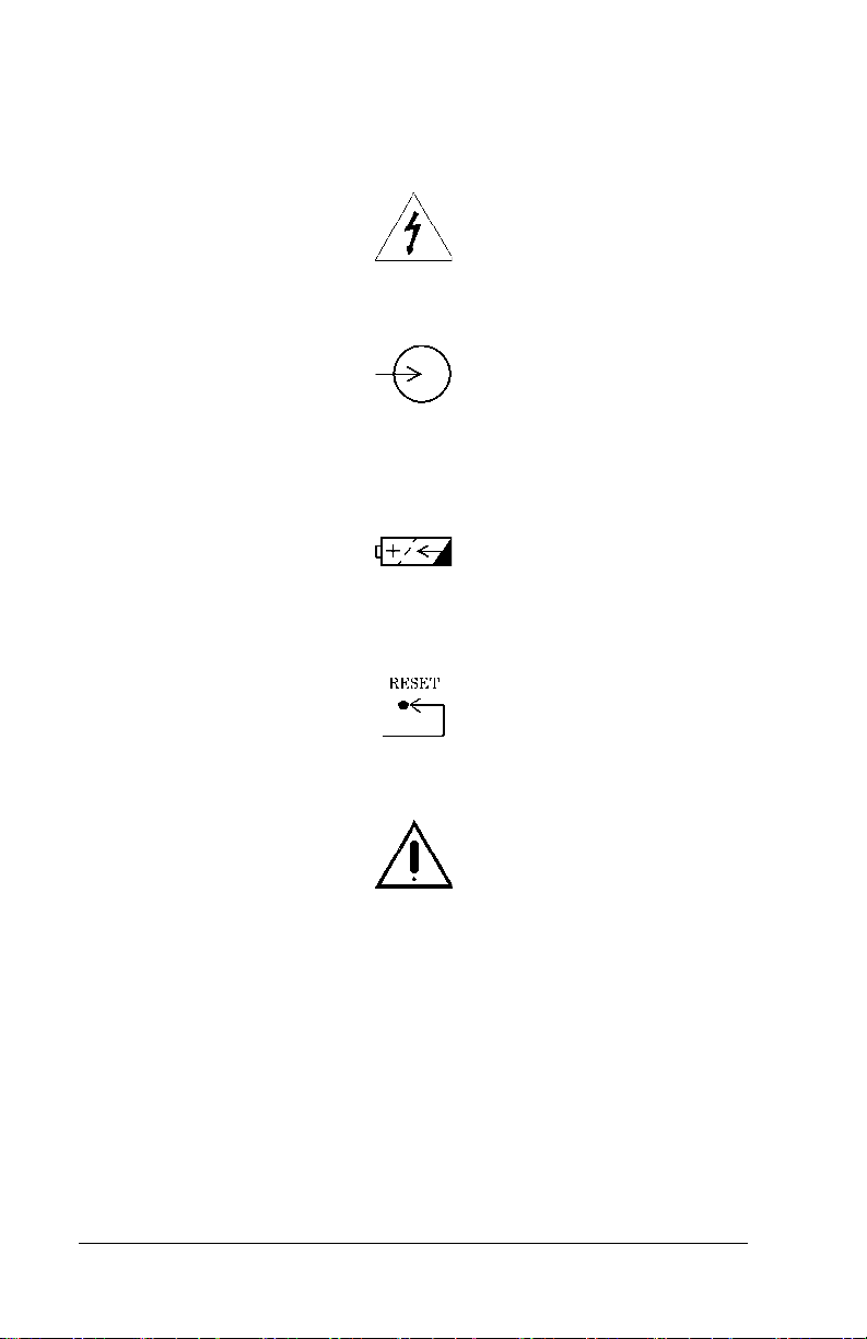
• The symbol below highlights an ELECTRICAL SHOCK HAZARD
WARNING:
Electrical Shock Hazard Warning
• The symbol below indicates INPUT RATING:
Input Rating Symbol
• The symbol below indicates that the product uses a
RECHARGEABLE BATTERY:
Rechargeable Battery Symbol
• The symbol below indicates RESET:
RESET Button Symbol
• The symbol below, when applied to the device, indicates:
ATTENTION: Consult Accompanying Documents
Page 1 - 2 Jaundice Meter (Model JM-103) User Manual (usr070)

DRAFT 18 May 2005
Intended Use
CAUTION:
Magnetic Resonance Imaging (MRI) procedures interfere with
Jaundice Meter operation. Inaccurate readings could occur.
CAUTION:
Do not use a mobile telephone when using the Jaundice Meter. A
measurement error could occur.
Intended Use of the Jaundice Meter
The Jaundice Meter (JM-103) is a non-invasive transcutaneous
bilirubinometer. It measures yellowness of subcutaneous tissue in
newborn infants.
The device is intended for use in hospitals or doctors’ offices under a
physician’s supervision or at their direction to assist clinicians in
monitoring of newborn infants. The device is not intended as a
standalone for diagnosis of hyperbilirubinemia. It is to be used in
conjunction with other clinical signs and laboratory measurements.
Newborn infants whose Jaundice Meter (JM-103) test results are
indicative of hyperbilirubinemia should be evaluated by their
physician(s) for appropriate patient management. Specific neonatal
patient bilirubin levels should be confirmed by other methods, such as
serum bilirubin, prior to treatment determinations.
The Jaundice Meter (JM-103) is not intended for home use.
Limitations (Doctors’ Office Use)
Use only on infants up to 14 days of age.
For doctors’ office application, use only the sternum location when
taking measurements.
Please be aware, performance in doctors’ offices may vary from
performance in hospitals.
Precocious Jaundice
Do not use this device on infants with precocious jaundice. If there is a
possibility that the infant is suffering from precocious jaundice, as a
result of an incompatible blood type or hemolytic jaundice, it is
recommended that the total serum bilirubin be measured.
Jaundice Meter (Model JM-103) User Manual (usr070) Page 1 - 3

DRAFT 18 May 2005
Intended Use of the User Manual
This manual provides instructions for installation, use, operator
maintenance, and troubleshooting of the Jaundice Meter (JM-103).
Konica Minolta/Dräger Medical cannot be responsible for the
performance of the Jaundice Meter if the user does not operate the unit
in accordance with the instructions, fails to follow maintenance
recommendations, or makes any repairs with unauthorized components.
Only qualified service personnel should perform repair.
Page 1 - 4 Jaundice Meter (Model JM-103) User Manual (usr070)

DRAFT 20 June 2005
Section 2
Introduction, Features,
and Specifications
Introduction
To prevent kernicterus in newborn infants, it is very important to detect
jaundice in its early stages. The Jaundice Meter (JM-103) is a noninvasive transcutaneous bilirubinometer. This hand-held device allows a
quick, non-invasive estimate of bilirubin concentration, to be used as an
aid for the management of jaundice in newborn infants. The
measurements are taken automatically when you place the instrument’s
measuring probe against the measuring site of the infant and press it
gently; the measured value is then displayed.
Measuring Point
Measurements must be taken only on the infant’s forehead (at hospital
sites only) or sternum (at hospital sites or physicians’ offices) where a
sufficient amount of blood is circulated. A possibility exists that the
bilirubin in the subcutaneous tissue may measure low for areas with
minimal blood flow or areas in which the subcutaneous tissue is subject
to keratinization.
Although correlation with serum bilirubin was observed for both
forehead and sternum measurements, the clinical studies performed with
the Jaundice Meter (JM-103) show consistently better results with
measurements taken at the sternum versus the forehead. There is a
possibility that this difference may be more pronounced for infants that
have been exposed to sunlight, such as infants seen at doctors’ offices.
Only sternum measurements were evaluated during the studies
conducted at doctors’ offices; correlation of forehead measurements
with serum bilirubin has not been evaluated, and the device is not
intended for forehead measurements at doctors’ offices. Therefore, use
the sternum location when taking measurements at doctors’ offices.
SPECIFICATIONS
Phototherapy
WARNING:
Do not use the Jaundice Meter after initiation of phototherapy or
after an exchange transfusion as results may be inaccurate under
these conditions. Patient injury could occur.
Jaundice Meter (Model JM-103) User Manual (usr070) Page 2 - 1
DRAFT 20 June 2005
Explanation of the Test
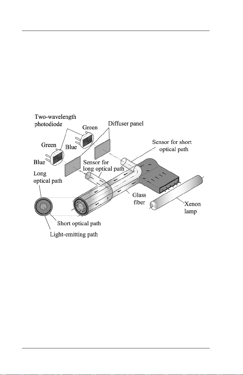
Measuring Principle
The Jaundice Meter determines the yellowness of an infant’s
subcutaneous tissue by measuring the difference in the optical densities
for light in the blue (450 nm) and green (550 nm) wavelength regions.
The measuring probe has two optical paths. This method allows for a
more precise measurement of yellowness in an infant’s subcutaneous
tissue by minimizing the influences of the melanin pigment and the skin
maturity.
When the measuring probe is pressed against the forehead or sternum of
the infant, the built-in xenon lamp flashes. The light from the xenon
lamp passes through the glass fiber and illuminates the skin. The light
scatters and is absorbed in the skin and subcutaneous tissue repeatedly,
and then finally returns to the sensor side of the glass fiber. Of the light
that returns, the part scattered from the shallow areas of the
subcutaneous tissue passes through the inner core, or short-optical path,
of the fiber. The part scattered from the deep areas of the subcutaneous
tissue passes through the outer core, or long-optical path, and then
reaches its corresponding photodiode.
Page 2 - 2 Jaundice Meter (Model JM-103) User Manual (usr070)
DRAFT 20 June 2005
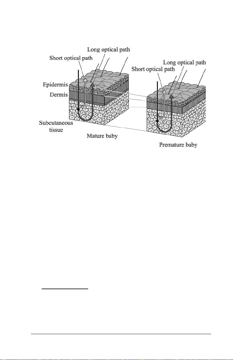
By calculating the difference in the optical densities, the parts that are
common to the epidermis and dermis are deducted, and as a result, the
difference in the optical densities between the two wavelength regions
can be obtained for the subcutaneous tissue only. Since the optical
density difference shows a linear correlation with the total serum
bilirubin concentration, it is converted to the estimated bilirubin
concentration and is indicated digitally.
The Jaundice Meter (JM-103) device software uses a correlation
coefficient to convert the measurement difference from the dual optical
path to an estimated bilirubin concentration. The calculation formula
used includes the correlation coefficients α and γ. These coefficients
were determined in pre-clinical testing. The equation used is as follows:
J
= α(L-S) + γ
sample
Where L and S are the long and short optical path measurements.
Use of the Device
Patient Population
The Jaundice Meter (JM-103) is indicated for use in neonatal patients
born >35 weeks gestation who have not undergone transfusion or
phototherapy treatment.
SPECIFICATIONS
Jaundice Meter (Model JM-103) User Manual (usr070) Page 2 - 3

DRAFT 20 June 2005
Averaging of Measurements
Averaging measurements may allow for more precise results. Assess the
advantages of using average measurements at your facility. There was
no significant difference between the averaged measurements and the
single measurement approaches in the largest study for sternum
measurements. The mean of three measurements showed the highest
degree of correlation (r=0.965), however, the difference was minimal
with a single measurement (r=0.963).
Averaging was not evaluated in the physicians’ office study.
Action Levels
Each facility should determine their own action levels based on studies
of performance of the device on their population. Appropriate action
levels may vary depending on performance of the device, such as
precision or correlation with serum bilirubin, in the hands of the user.
Some factors that could affect performance of the device or appropriate
action levels include skin color, age, or measurement site. The bias
relative to serum bilirubin differs between hospital versus physicians’
office sites (see Appendixes A and B). Different action levels may be
appropriate for hospital versus physicians’ offices. Careful selection of
action levels should be made so that false negatives do not prevent
appropriate follow up measures.
Calibration
There is no user calibration of this device. The system does include a
checker that measures the intensity of light from the device to ensure the
light output is acceptable for proper use.
Processing of Measured Values
The Jaundice Meter (JM-103) determines the yellowness of the
subcutaneous tissue by measuring the difference in the optical densities
for light in the blue and green wavelength regions. The optical density
difference has been shown to have a linear correlation with serum
bilirubin concentration. The device computes an estimated bilirubin
concentration based on this linear correlation and provides the value on
the display.
Page 2 - 4 Jaundice Meter (Model JM-103) User Manual (usr070)
DRAFT 20 June 2005
Features
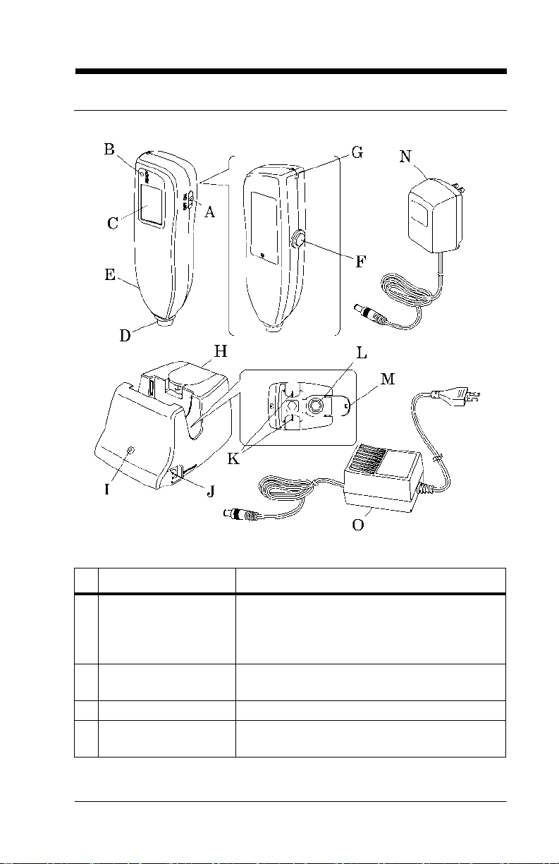
Controls, Indicators, and Connections
SPECIFICATIONS
Controls, Indicators, and Connections
Name Function
A Power switch Turns the Jaundice Meter on and off.
When used with the Reset button, the device
switches to Check Mode and changes the unit
of measurement.
B Ready lamp Illuminates to indicate that the Jaundice Meter
is ready for the next measurement.
C Display Displays the measured value.
D Measuring probe Takes the measurement when pressed against
the measuring point.
Jaundice Meter (Model JM-103) User Manual (usr070) Page 2 - 5

DRAFT 20 June 2005
Name Function
E Charger section Connect the charger unit to the charger sec-
tion.
F Reset button Deletes the currently displayed measured
value and prepares for the next measurement.
When used with the Power switch, the device
switches to Check Mode and changes the unit
of measurement.
G Strap attachment area Is where the strap attaches.
H Checker cover Open this checker cover to check the Jaundice
Meter.
I Charger lamp Illuminates to indicate that the Jaundice Meter
is charging.
J DC jack Connect the AC adapter to this jack.
K Charger jack Connect the main body to this jack.
L Checker Checks for the intensity of light output by tak-
ing measurements in Check Mode.
M Standard checker
values
N DC plug Connect the charger’s DC jack to this.
O DC Plug (interna-
tional)
For reference.
Connect the charger’s DC jack to this.
Page 2 - 6 Jaundice Meter (Model JM-103) User Manual (usr070)
DRAFT 20 June 2005
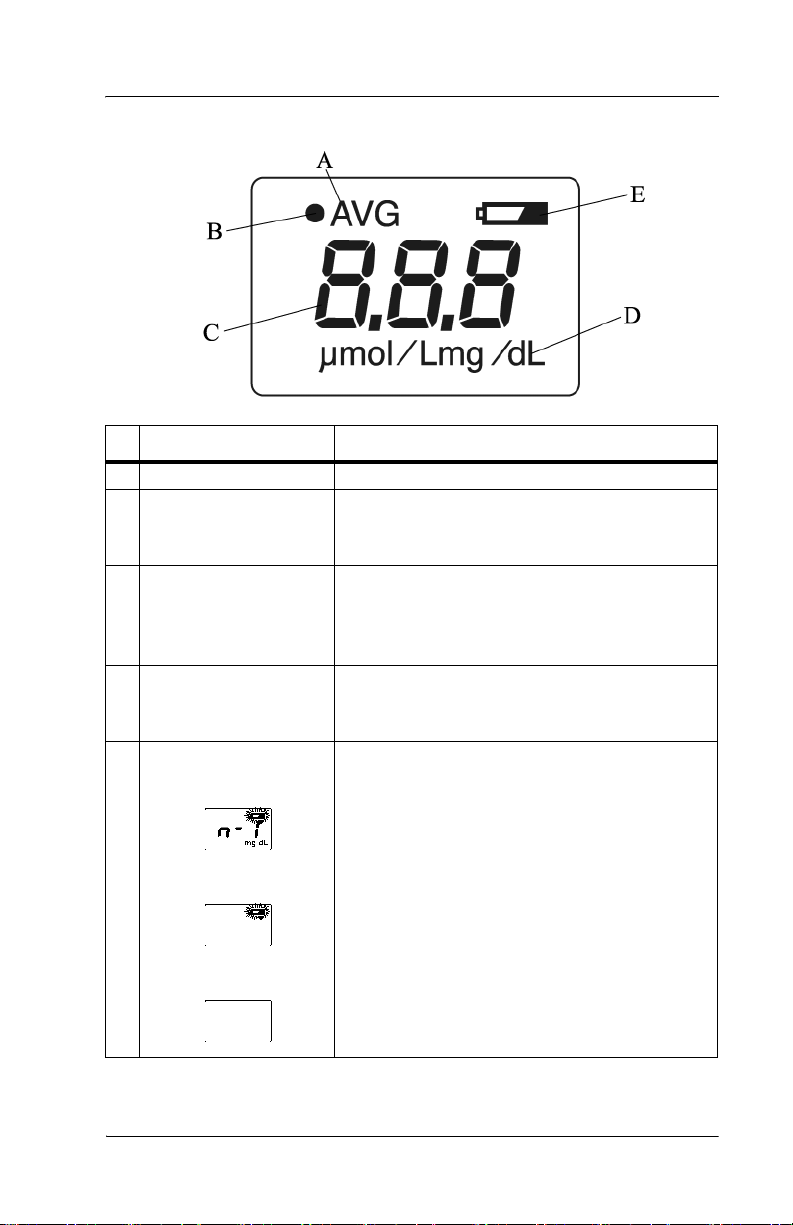
Display
Name Function
A AVG Illuminates during averaging measurement.
B Optical path indicator
(•)
C Value Displays the measured value.
D Unit of measurement Displays the unit of measurement in either
E Battery indicator When the battery power is low, the battery
When verifying light output with the checker,
(•)illuminates when the L-value appears and
extinguishes when the S-value appears.
NOTE: When the measured value is greater
than 20 mg/dl, the display shows “---” and the
physician should be contacted.
milligrams per deciliter (mg/dL) or micromoles of solute per liter (µmol/L)
indicator blinks. Charge the battery as soon as
possible (see “Charging the Battery” on page
4-1).
If only the battery indicator lights, the battery
has run out. Go to “Charging the Battery” on
page 4-1.
If the power is on and the display is blank, the
battery is completely exhausted. Go to
“Charging the Battery” on page 4-1.
SPECIFICATIONS
Jaundice Meter (Model JM-103) User Manual (usr070) Page 2 - 7

DRAFT 20 June 2005
Standard Features
• Jaundice Meter (JM-103)
• Charger unit (Model JM-A30) with a checker
• AC adapter (Model JM-A31)
• Carrying case and wrist strap
Page 2 - 8 Jaundice Meter (Model JM-103) User Manual (usr070)

DRAFT 20 June 2005
Specifications
Standard Features
Feature Dimension
Model name JM-103
Measuring method Determines the yellowness of the
subcutaneous tissue by using two
optical paths to measure the optical
density difference at two wavelengths
Measurement range 0.0 mg/dL to 20 mg/dL or 0 µmol/L
to 340 µmol/L
Clinical Data Standard Error of
Estimate (SEE) *
Light source Pulse xenon arc lamp
Light source life 150000 measurements
Sensors Silicon photodiodes
Power source 2.4 V, Special Ni-MH battery
Protection type and level Internally-powered instrument, BF-
Minimum number of
measurements when fully charged
Operating temperature range 10°C (50°F) to 40°C (104°F)
Operating relative humidity range 30% to 95% non-condensing
Storage temperature range -10°C (14°F) to 50°C (122°F)
Storage relative humidity range 30% to 95% non-condensing
Dimensions 48 mm (1.9") wide x 15.5 cm (6.1")
Weight, including battery 150 g (5.3 oz)
AC adapter input for North America 120V, 50/60 Hz, 10 W
AC adapter input for
international use (old)
AC adapter input for
international use (new)
AC adapter output 9V, 500 mA, 4.5W
± 1.5 mg/dL or ± 25.5 µmol/L
type
400 single measurements
high x 33 mm (1.3") deep
200V-240V, 50/60 Hz, 12.5VA
100V-240V, 50/60 Hz, 0.14-0.07A
SPECIFICATIONS
*The standard deviation shown above is based on the average of the
Jaundice Meter (Model JM-103) User Manual (usr070) Page 2 - 9

DRAFT 20 June 2005
clinical data available. On average, 66% of results fall within this range,
and the remainder fall outside this range. This value can be affected by
variables such as age, skin color, and preformance of the device in the
hands of the user. Refer to Appendixes A and B for a detailed
description of results by clinical site, measurement location, and patient
demographics. The SEE shown above are based on the clinical data
available and can be affected by variables such as infant developmental
age, ethnicity, etc. Therefore, we recommend that the JM-103 be used in
conjunction with other clinical signs and laboratory measurements.
"Specific Bilirubin Measurement" should be confirmed by other
methods such as laboratory blood serum analysis.
Regulations, Standards, and Codes
In North America
With respect to electrical shock, fire, and
mechanical hazards only, this instrument complies
with UL 60601-1 and CAN/CSA C22.2 No. 601.1.
In Europe, this instrument complies with EN60601-1, EN60601-1-2,
and EN ISO13485, and EN ISO14971.
Directive 2002/96/EC of the European Parliament and of the Council of
2003-01-27 on Waste Electrical and Electronic Equipment (WEEE)
Annex IV, prEN 50419 applies.
Device Classification
The Jaundice Meter (JM-103) meets the requirements for the following
classifications:
• Protection against electrical shock: Internally powered
• Type of applied part: BF
• Degree of protection against harmful ingress of water: Not applicable
• Not suitable for use in the presence of flammable anesthetic mixture
with air or oxygen or nitrous oxide.
• Mode of operation of equipment: Continuous while in use (IEC
60601-1)
Page 2 - 10 Jaundice Meter (Model JM-103) User Manual (usr070)

DRAFT 20 June 2005
Electromagnetic Compatibility (EMC) Guidance and Manufacturer’s Declarations
Guidance and Manufacturer’s Declaration—Electromagnetic
Emissions
The Jaundice Meter (JM-103) is intended for use in the electromagnetic environment specified below. The customer or user of the unit
should ensure that the unit is used in such an environment.
Emissions Test Compliance
Radio frequency
Group 1 The Jaundice Meter (JM-103)
(RF) emissions
—CISPR 11
Electromagnetic
Environment—Guidance
uses RF energy only for its internal function. Therefore, its RF
emissions are very low and are
not likely to cause interference
with nearby electronic equipment.
RF emissions—
CISPR 11
Harmonic Emissions—IEC
61000-3-2
Voltage fluctuations/ flicker
Class B The Jaundice Meter (JM-103) is
suitable for use in all establish-
Class A
ments, including domestic and
those directly connected to the
public low-voltage power supply
Complies
network that supplies buildings
used for domestic purposes.
emissions—IEC
61000-3-3
SPECIFICATIONS
Jaundice Meter (Model JM-103) User Manual (usr070) Page 2 - 11

DRAFT 20 June 2005
Guidance and Manufacturer’s Declaration—Electromagnetic
Immunity
The Jaundice Meter (JM-103) is intended for use in the electromagnetic environment specified below. The customer or user of the unit
should ensure that the unit is used in such an environment.
Immunity
Test
Electrostatic
discharge
(ESD)—
IEC 610004-2
Electrical
fast transient/burst
—IEC
61000-4-4
Surge—IEC
61000-4-5
IEC 60601
Test L e v e l
± 6 kV contact
± 8 kV air
± 2 kV for
power supply lines
± 1 kV
differential
mode
Compliance
Level
± 6 kV contact
± 8 kV air
± 2 kV for
power supply lines
± 1 kV
differential
mode
Electromagnetic
Environment—
Guidance
The floors should be
wood, concrete, or
ceramic tile. If floors are
covered with synthetic
material, the relative
humidity should be at
least 30%.
Mains power quality
should be that of a typical
commercial or hospital
environment.
Mains power quality
should be that of a typical
commercial or hospital
environment.
Page 2 - 12 Jaundice Meter (Model JM-103) User Manual (usr070)

DRAFT 20 June 2005
Guidance and Manufacturer’s Declaration—Electromagnetic
Immunity
The Jaundice Meter (JM-103) is intended for use in the electromagnetic environment specified below. The customer or user of the unit
should ensure that the unit is used in such an environment.
Immunity
Test
Voltage
dips, short
interruptions, and
voltage variations on
power supply input
lines—IEC
61000-4-11
Power frequency
(50/60 Hz)
magnetic
field—IEC
61000-4-8
IEC 60601
Test Level
< 5% U
95% dip in
) for 0.5
U
T
cycles
40% U
(60% dip in
U
) for 5
T
cycles
70% U
(30% dip in
U
) for 25
T
cycles
< 5% U
95% dip in
U
) for 5
T
seconds
(>
T
T
T
(>
T
Compliance
Level
< 5% U
T
(>
95% dip in
) for 0.5
U
T
cycles
40% U
T
(60% dip in
U
) for 5
T
cycles
70% U
T
(30% dip in
U
) for 25
T
cycles
< 5% U
T
(>
95% dip in
U
) for 5
T
seconds
3 A/m 3 A/m The power frequency
Electromagnetic
Environment—
Guidance
Mains power quality
should be that of a typical
commercial or hospital
environment. If the user
of the unit requires continued operation during
power mains interruptions, it is recommended
that the unit be powered
from an uninterruptable
power supply or battery.
magnetic fields should be
at levels characteristic of
a typical location in a typical commercial or hospital environment.
SPECIFICATIONS
NOTE:
U
is the AC mains voltage prior to the application of the test
T
level.
Jaundice Meter (Model JM-103) User Manual (usr070) Page 2 - 13
DRAFT 20 June 2005
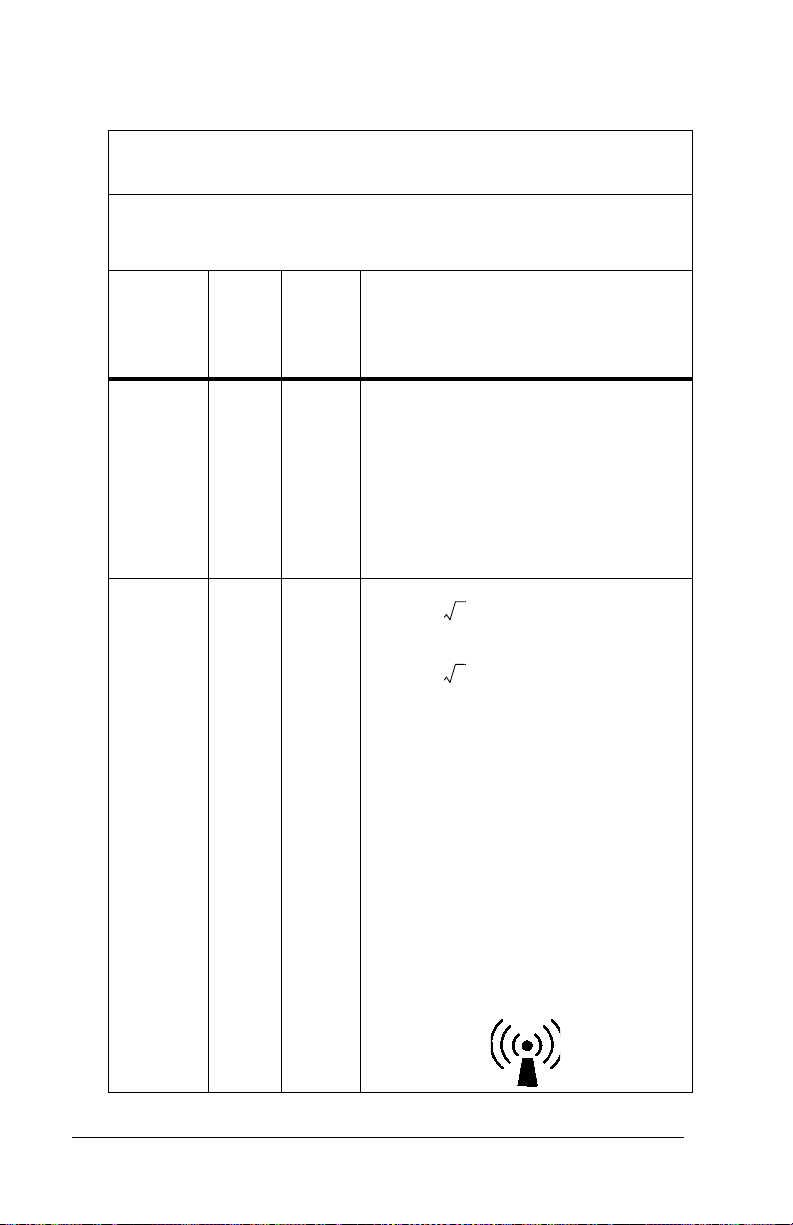
Guidance and Manufacturer’s Declaration—Electromagnetic
Immunity
The Jaundice Meter (JM-103) is intended for use in the electromagnetic environment specified below. The customer or user of the unit
should ensure that the unit is used in such an environment.
Immunity
Test
Conducted
RF—IEC
61000-4-6
Radiated
RF—IEC
61000-4-3
IEC
60601
Test
Level
3 Vrms
150
kHz to
80
MHz
3 V/m 3 V/m
80
MHz
to 2.5
GHz
Compli
ance
Level
Electromagnetic Environment—
Guidance
Recommended Separation Distance
3 Vrms Portable and mobile RF communica-
tion equipment should be used no
closer to any part of the Jaundice Meter
(JM-103), including cables, than the
recommended separation distance calculated from the equation applicable to
the frequency of the transmitter.
Recommended Separation Distance
d 1.2 P=
d 2.3 P=
80 MHz to 800 MHz
800 MHz to 2.5 GHz
where P is the maximum output power
rating of the transmitter in watts (W)
according to the transmitter manufacturer and d is the recommended separation distance in meters (m).
Field strengths from fixed RF transmitters, as determined by an electromag-
netic site survey
the compliance level in each frequency
b
range.
a
, should be less than
Interference may occur in the vicinity
of equipment marked with the following symbol:
Page 2 - 14 Jaundice Meter (Model JM-103) User Manual (usr070)

DRAFT 20 June 2005
Guidance and Manufacturer’s Declaration—Electromagnetic
Immunity
The Jaundice Meter (JM-103) is intended for use in the electromagnetic environment specified below. The customer or user of the unit
should ensure that the unit is used in such an environment.
IEC
Immunity
Test
60601
Test
Level
NOTE:
At 80 MHz and 800 MHz, the higher frequency range applies.
NOTE:
These guidelines may not apply in all situations. Electromagnetic
propagation is affected by absorption and reflection from
structures, objects, and people.
a. Field strengths from fixed transmitters, such as base stations for radio,
cellular/cordless telephones, land-mobile radios, amateur radio, AM and FM
radio broadcast, and TV broadcast cannot be predicted theoretically with
accuracy. To assess the electromagnetic environment due to fixed-RF
transmitters, an electromagnetic site survey should be considered. If the
measured field strength in the location in which the unit is used exceeds the
applicable RF compliance level, observe the unit to verify normal operation.
If abnormal performance is observed, additional measures may be necessary,
such as reorienting or relocating the unit.
b. Over the frequency range 150 kHz to 80 MHz, field strengths should be < 3
V/m.
Compli
ance
Level
Electromagnetic Environment—
Guidance
Recommended Separation Distance
SPECIFICATIONS
Jaundice Meter (Model JM-103) User Manual (usr070) Page 2 - 15

NOTES:
DRAFT 20 June 2005
Page 2 - 16 Jaundice Meter (Model JM-103) User Manual (usr070)

DRAFT 18 May 2005
Section 3
Precautions and Safety Tips
Precautions
WARNING:
Do not use the instrument in areas where flammable or
combustible gases, such as anesthetic gases, are present. Doing
so could result in a fire. Personal injury or equipment damage
could occur.
WARNING:
If the instrument, the charger unit, or the AC adapter are
damaged, or if smoke or an odd smell occurs, do not use the
instrument, the charger unit, or the AC adapter. In such situations,
immediately turn off the instrument, unplug the AC adapter from
its power source, and contact the nearest authorized service
facility. Failure to do so could result in fire, personal injury, or
equipment damage.
WARNING:
Do not use the Jaundice Meter after initiation of phototherapy or
after an exchange transfusion as results may be inaccurate under
these conditions. Patient injury could occur.
SHOCK HAZARD:
Always plug the instrument into an AC outlet of the correctly rated
voltage and frequency. Failure to do so could result in fire,
personal injury, or equipment damage.
SHOCK HAZARD:
Do not disassemble or modify the instrument, the charger unit, or
the AC adapter. Fire, personal injury, or equipment damage could
occur.
CAUTION:
Do not place the instrument on an unstable or sloping surface.
The instrument or charger unit could drop or overturn. Equipment
damage could occur.
Jaundice Meter (Model JM-103) User Manual (usr070) Page 3 - 1

DRAFT 18 May 2005
CAUTION:
Do not use the instrument in direct sunlight. Equipment damage
could occur.
CAUTION:
The Jaundice Meter is a precision instrument. When using it, do
not drop it, expose it to shocks or strong vibrations, or place
heavy objects on it. Equipment damage could occur.
CAUTION:
Do not allow blood or other liquids to come in contact with the
instrument. Should blood or other liquids come in contact with the
instrument, immediately clean the instrument (see “Cleaning” on
page 6-1). Failure to do so could result in equipment damage.
CAUTION:
The instrument has a built-in, non-user-replaceable battery. Do
not disassemble the instrument to replace the battery. To replace
the battery, contact your dealer or authorized service center.
Failure to do so could result in equipment damage.
Page 3 - 2 Jaundice Meter (Model JM-103) User Manual (usr070)

DRAFT 18 May 2005
Electromagnetic Compatibility Precautions
General information on electromagnetic compatibility (EMC)
according to the international EMC standard IEC 60601-12: 2001
Pins of connectors identified with the ESD warning
symbol shall not be touched and not be connected
unless ESD precautionary procedures are used. Such
precautionary procedures may include antistatic
clothing and shoes, the touch of a ground stud before
and during connecting the pins or the use of electrically
isolating and antistatic gloves. All staff involved in the
above shall receive instruction in these procedures.
NOTE:
Portable and mobile RF communications equipment can affect medical
electrical equipment.
NOTE:
Medical electrical equipment needs special precautions regarding
electromagnetic compatibility (EMC) and needs to be installed and put
into service according to the EMC information provided in the technical
documentation available from Dräger Service upon request.
Jaundice Meter (Model JM-103) User Manual (usr070) Page 3 - 3
DRAFT 18 May 2005
Safety Tips
WARNING:
This instrument emits intense light to take its measurements.
Take measurements only at the forehead or sternum (hospital
application). Doctors’ office use should be performed at the
sternum only. Do not press the measuring probe when it is
directed toward the infant’s or caregiver’s eyes. Damage to the
eyes could occur.
WARNING:
Before use, clean the measuring probe by wiping it with medicinal
alcohol. Failure to do so could result in the spread of infection or
infant injury.
WARNING:
The charger unit (JM-A30) and the AC adapter (JM-A31) are
solely designed for use with the Jaundice Meter (JM-103). Use
them only when charging the instrument. Using them to charge
other equipment could result in personal injury or equipment
damage.
WARNING:
Only facility-authorized personnel should troubleshoot the
Jaundice Meter. Troubleshooting by unauthorized personnel
could result in personal injury or equipment damage.
WARNING:
Follow the product manufacturer’s instructions. Failure to do so
could result in personal injury or equipment damage.
WARNING:
This product has been validated with the accessories and options
listed in this manual and found to comply with all relevant safety
and performance requirements applicable to the device. It is
therefore the responsibility of that person or organization who
makes an unauthorized modification, or incorporates an
unapproved attachment to the device, to ensure that the system
still complies with those requirements. [IHA036]
Page 3 - 4 Jaundice Meter (Model JM-103) User Manual (usr070)
Loading...