


Technical Service Manual
Gamma / Gamma XL Patient Monitors
Monitor System
Revision 0 6013.053 MS14879
Emergency Care • OR/ Anesthesia • Critical Care • Perinatal Care • Home Care |
Because you care |
Copyright by Dräger Medical AG & Co. KGaA, Lübeck, Germany.
No reproduction allowed for commercial purposes.
Read and understand the Instructions for Use/Operator’s Manual.
This Technical Documentation does not replace the Instructions for Use/Operator’s Manual.
The warranty and liability conditions of the general terms and conditions for business transactions of Dräger Medical AG & Co. KGaA are not extended by this Technical Documentation.
Observe all applicable technical laws and regulations.
Insofar as reference is made to laws, regulations or standards, these are based on the legal system of the Federal Republic of Germany. Observe the laws and regulations applicable in your country.

K6013053IECIVZ.fm 03.12.04 |
All rights reserved. Copyright reserved. |
Contents
General
1 |
Advisory |
3 |
|
2 |
Important information |
3 |
|
|
2.1 |
Symbols and Definitions ......................................................................................................... |
3 |
3 |
Introduction |
4 |
|
|
3.1 |
Service Strategy ..................................................................................................................... |
4 |
4 |
Product Overview |
5 |
|
|
4.1 |
Monitored Patient Parameters ................................................................................................ |
5 |
|
4.2 |
Gamma/Gamma XL Monitor Controls .................................................................................... |
5 |
|
4.3 |
TFT-LCD Display .................................................................................................................... |
5 |
|
4.4 |
Alarms .................................................................................................................................... |
5 |
|
4.5 |
Monitor/Software Tracking ...................................................................................................... |
6 |
5 |
Technical Data |
6 |
|
|
5.1 |
General ................................................................................................................................... |
6 |
|
5.2 |
Environmental ........................................................................................................................ |
6 |
|
5.3 |
Display .................................................................................................................................... |
7 |
|
5.4 |
Outputs ................................................................................................................................... |
8 |
|
5.5 |
Connectors ............................................................................................................................. |
8 |
6 |
Monitor Controls |
9 |
|
|
6.1 |
Main Screen Key .................................................................................................................... |
9 |
|
6.2 |
Menu Key ............................................................................................................................... |
9 |
|
6.3 |
Alarm Limits Key .................................................................................................................. |
10 |
|
6.4 |
Alarm Silence Key ................................................................................................................ |
10 |
|
6.5 |
All Alarms Off Key ................................................................................................................ |
10 |
|
6.6 |
NBP Start/Stop Key .............................................................................................................. |
10 |
|
6.7 |
Fast Access Key ................................................................................................................... |
10 |
|
6.8 |
Record Key ........................................................................................................................... |
10 |
Dräger Medical AG & Co. KGaA |
Contents |
I |

Contents
Function Description
1 |
Overview |
15 |
|
2 |
Parameter Inputs |
15 |
|
3 |
Main PC Board |
15 |
|
|
3.1 |
LCD Control .......................................................................................................................... |
16 |
|
3.2 |
Network Interface ................................................................................................................. |
16 |
|
3.3 |
Front Panel Circuitry ............................................................................................................. |
16 |
|
3.4 |
Pod Interface ........................................................................................................................ |
16 |
|
3.5 |
Battery Control and ON/OFF Control ................................................................................... |
16 |
|
3.6 |
BOOT Process, Flash Memory, and DRAM ......................................................................... |
16 |
|
3.7 |
SRAM ................................................................................................................................... |
17 |
|
3.8 |
68HC912D60A Microcontroller ............................................................................................. |
17 |
4 |
Front End |
17 |
|
|
4.1 |
NBP Control .......................................................................................................................... |
17 |
|
4.2 |
Safety ................................................................................................................................... |
17 |
5 |
Physiological Parameter Data Acquisition |
18 |
|
|
5.1 |
ECG/Resp ............................................................................................................................ |
18 |
|
5.2 |
Respiration ........................................................................................................................... |
20 |
|
5.3 |
SpO2 ..................................................................................................................................... |
21 |
|
5.4 |
Invasive Blood Pressure ....................................................................................................... |
23 |
|
5.5 |
Non-Invasive Blood Pressure ............................................................................................... |
24 |
|
5.6 |
Temperature Circuit .............................................................................................................. |
27 |
6 |
etCO2 Pod |
28 |
|
7 |
Power Supply System |
29 |
|
|
7.1 |
Main Battery ......................................................................................................................... |
29 |
|
7.2 |
AC Power Adapter ................................................................................................................ |
30 |
|
|
|
|
II |
Dräger Medical AG & Co. KGaA |
Contents |
|
Copyright .reserved rights All |
K6013053IECIVZ |
.reserved |
04.12.03 fm. |

Contents
Maintenance Procedures
1 |
Maintenance Procedure |
33 |
|
|
1.1 |
General ................................................................................................................................. |
33 |
|
1.2 |
Battery .................................................................................................................................. |
33 |
|
1.3 |
Replacing NBP Air Intake Filter ............................................................................................ |
33 |
|
1.4 |
Safety and Function Tests .................................................................................................... |
34 |
|
1.5 |
Acceptance Test Report ....................................................................................................... |
45 |
Schematics and Diagrams
1 |
IBP Connector |
49 |
2 |
MultiMed Pod Connector |
49 |
3 |
Docking Station Connector |
50 |
4 |
Alarm Cable (Unterminated) |
50 |
5 |
Interface Plate Connector |
51 |
6 |
Recorder/Alarm Y-cable |
51 |
7 |
Infinity Docking Station Connectors |
52 |
8 |
PodPort Connector Pins |
53 |
K6013053IECIVZ.fm 03.12.04 |
All rights reserved. Copyright reserved. |
Fault-Cause-Remedy
1 |
Troubleshooting |
57 |
|
|
1.1 |
Power Problems ................................................................................................................... |
57 |
|
1.2 |
Optical Encoder Malfunction ................................................................................................ |
59 |
|
1.3 |
TFT-LCD Display Malfunction .............................................................................................. |
59 |
|
1.4 |
Fixed Key Fails to Function .................................................................................................. |
60 |
Dräger Medical AG & Co. KGaA |
Contents |
III |

Contents |
|
|
1.5 |
Visual or Audible Alarm Reporting Failure ............................................................................ |
60 |
1.6 |
NBP Malfunction ................................................................................................................... |
60 |
1.7 |
etCO2 Malfunction ................................................................................................................ |
61 |
1.8 |
No Printout from Recorder .................................................................................................... |
62 |
1.9 |
Isolating Cable Malfunctions ................................................................................................. |
63 |
1.10 |
Patient-Related Data Not Retained or Monitor Fails to Compute Trends ............................. |
63 |
Annex
Spare parts list
Test List
Problem Report
Copyright .reserved rights All |
K6013053IECIVZ |
.reserved |
04.12.03 fm. |
IV |
Dräger Medical AG & Co. KGaA |
Contents |

General
1

2
Gamma / Gamma XL Patient Monitor |
General |
|
|
General
1 Advisory
2Important information
This document corresponds to the version/revision level effective at the time of system delivery. Revisions to hardcopy documentation are not automatically distributed.
The installation and service of equipment described herein is to be performed by qualified personnel who are employed by Dräger Medical or one of its affiliates or who are otherwise authorized by Dräger Medical or one of its affiliates to provide such services.
Assemblers and other persons who are not employed by or otherwise directly affiliated with or authorized by Dräger Medical or one of its affiliates are directed to contact one of the local offices of Dräger Medical or one of its affiliates before attempting installation or service procedures.
This Technical Documentation/Service Manual conforms to the International Standard IEC 60601-1.
Read each step in every procedure thoroughly before beginning any test. Always use the proper tools and specified test equipment. If you deviate from the instructions and/or recommendations in this Technical Documentation/ Service Manual, the equipment may operate improperly or unsafely, or the equipment could be damaged.
The maintenance procedures described in this Technical Documentation/ Service Manual may be performed by qualified service personnel only. These maintenance procedures do not replace inspections and servicing by Dräger Medical.
Gamma Gamma XL SM General.fm 03.12.04 |
All rights reserved. Copyright reserved. |
Strictly follow the Instructions for Use/Operating Instructions! This Technical Documentation does not replace the Instructions for Use/Operating Instructions. Any use of the product requires full understanding and strict observation of the product-specific Instructions for Use/Operating Instructions.
Unless otherwise stated, reference is made to laws, regulations or standards (as amended) applicable in the Federal Republic of Germany.
2.1Symbols and Definitions
This symbol is used to provide important information that, if ignored, could lead directly to a patient’s or operator’s injury. It is also used to provide important information that, if ignored, could lead directly to equipment damage and, indirectly, to a patient’s injury.
The following three alert levels are used in this documentation to indicate a hazardous situation and how to avoid it.
Dräger Medical AG & Co. KGaA |
6013.053 |
Revision 0 Released |
3 |
General |
Gamma / Gamma XL Patient Monitor |
|
|
Danger |
Danger indicates an imminently hazardous situation |
|
which, if not avoided, will result in death or serious |
|
injury. |
Warning |
Warning indicates a potentially hazardous situation |
|
which, if not avoided, could result in death or serious |
|
injury. |
Caution |
Caution indicates a hazardous situation which, if not |
|
avoided, may result in minor or moderate injury. Caution |
|
may also be used to alert against unsafe practices. |
Danger
Danger indicates an imminently hazardous situation which, if not avoided, will result in death or serious injury.
Note
This symbol is used to provide additional information, operating tips, or maintenance suggestions.
|
|
Definitions according to German standard DIN 31051: |
|
|
|
Inspection |
= examination of actual condition |
|
|
Servicing |
= measures to maintain specified condition |
|
|
Repair |
= measures to restore specified condition |
|
|
Maintenance |
= inspection, servicing, and repair |
3 |
Introduction |
In keeping with the service strategy for the Infinity Gamma Patient Monitor |
|
|
|
and the Infinity Gamma XL Patient Monitor, this technical manual provides |
|
|
|
the necessary information required to maintain a Gamma/Gamma XL Patient |
|
|
|
Monitor in the field. The Gamma and Gamma XL are both stationary and por- |
|
|
|
table monitors designed to monitor patient vital signs (refer to user’s guide for |
|
|
|
monitoring options). For stationary operation near a bedside, the monitor is |
|
|
|
connected to an AC/DC power adapter or placed on a specially designed |
|
|
|
docking station attached to a shelf, wall, or rolling stand that securely locks it |
|
|
|
into place. While on the docking station, the monitor is powered by an IDS |
|
|
|
power supply. When the monitor is detached from an IDS, it is powered by a |
|
|
|
lead acid battery or by an optional Lithium ion battery. The monitor is reat- |
|
|
|
tached to the AC/DC Power Adapter or placed back on an IDS to recharge |
|
|
|
the battery. |
|
3.1 |
Service Strategy |
The monitor has been designed for high reliability, with an estimated MTBF of |
|
|
|
50,000 hours (5.7 yrs.) of continuous operation.Therefore, the service strat- |
|
|
|
egy is based on few failures in the field, a clear definition of failure analysis by |
|
|
|
field service personnel, and a quick repair turnaround. The field repair philos- |
|
|
|
ophy is based on the distributed and approved spare parts list. |
|
|
|
This manual is intended to serve as a source of technical information, for |
|
|
|
qualified field service personnel to use in maintaining a Gamma/Gamma XL |
|
|
|
patient monitor in accordance with the Dräger Medical Service Strategy. Field |
|
|
|
service is expected to be successful “First-Time Every Time.” |
|
|
|
|
|
4 |
Dräger Medical AG & Co. KGaA |
6013.053 |
Revision 0 Released |
All rights reserved. Copyright reserved. |
Gamma Gamma XL SM General.fm 03.12.04 |
Gamma Gamma XL SM General.fm 03.12.04 |
All rights reserved. Copyright reserved. |
Gamma / Gamma XL Patient Monitor |
General |
||
|
|
|
|
4 |
Product Overview |
Gamma and Gamma XL Patient Monitors are light-weight, battery-equipped, |
|
|
|
hand-held or semi-permanently mounted devices for general purpose moni- |
|
|
|
toring of a preconfigured set of physiological parameters. When not con- |
|
|
|
nected to a hospital’s main ac power, they use a battery with approxi-mately |
|
|
|
1¼ hours (3 hrs. for Li option battery) of operating time. A power adapter or |
|
|
|
IDS, which also charges the battery, can be used to operate the monitor from |
|
|
|
the hospital’s main ac power circuit. |
|
4.1Monitored Patient The Gamma/Gamma XL monitors the following physiological parameters:
Parameters |
• ECG (three-lead, five-lead, or six-lead pod) |
|
•Respiration
•Pulse Oximetry (SpO2 and PLS)
•Temperature
•NBP
•IBP1, IBP2 (locked option)
•etCO2 via PodComm Port (locked option)
•Arrhythmia
•OCRG (locked option)
•Dual Lead S-T Segment Analysis (locked option)
•Anesthetic Gas Monitoring (Gamma XL only, locked option)
4.2Gamma/Gamma XL All functions are controlled by a 16-position rotary knob and nine front panel
|
Monitor Controls |
fixed keys - Alarm Silence, Record, Alarm Limits, NBP Start/Stop, All Alarms |
|
|
Off, Fast Access, Main Screen, Menu, and ON/OFF. Turning the rotary knob |
|
|
locates different menu items, and pressing the knob in selects the item. |
|
|
Depending on the item selected, pressing the knob in may either bring up |
|
|
another menu or initiate an action. See Section 5 Technical Data. For detailed |
|
|
operating instructions, consult the Gamma/Gamma XL Patient Monitor User |
|
|
Guide applicable to the installed software. |
4.3 |
TFT-LCD Display |
The Gamma Patient Monitor has a 6.5 inch (16.5cm), 3-channel (optional 4th |
|
|
channel) color TFT-LCD display. The Gamma XL Patient Monitor has an 8.3 |
|
|
inch (21cm), 4-channel color TFT-LCD display. Waveforms display in Erase |
|
|
Bar mode at 25 ±20% mm/s (except for respiration and etCO2 waveforms |
|
|
which display at 6.25 ±20% mm/s). All displays for a given parameter (label, |
|
|
unit of measure, and waveform) are in the same color. If a waveform is not |
|
|
displayed for a parameter, its label is gray. |
4.4 |
Alarms |
Alarm limits can be set either on a user-definable setup table, or automatic- |
ally based on current parameter values. Three alarm grades, each with a distinct alarm tone, announce alarm situations of varying severity, as follows:
• life-threatening (asystole or ventricular fibrillation - red)
• serious (parameter limit alarms - yellow)
• advisory (technical alarms - white)
The message field background and parameter field of the parameter in alarm, and alarm LED, are displayed in the color associated with the alarm grade as given above.
Dräger Medical AG & Co. KGaA |
6013.053 |
Revision 0 Released |
5 |
General |
Gamma / Gamma XL Patient Monitor |
|
|
4.5Monitor/Software Each monitor has a unique ID chip installed in its rear housing for diagnostic
Tracking |
and tracking purposes, and un/locking optional software features. |
5 Technical Data
5.1General
Technical Data included in this Section is as of publication date of this Manual. Changes are reported in User Guide applicable to installed SW.
Table 1 General Specifications
|
Parameter |
|
|
|
Specification |
|
|
|
|
|
|
|
|
|
|
|
|
|
Power Requirements |
|
|
|
100-250 VAC through AC power adapter |
|
|
|
|
|
|
|
|
|
|
|
|
|
Mains Frequency |
|
|
|
50/60 Hz |
|
|
|
|
|
|
|
|
|
|
|
|
|
AC Power Consumption |
|
|
|
60 VA AC |
|
|
|
|
|
|
|
|
|
|
|
|
|
Battery Type |
|
|
|
Lead-acid: PANASONIC LC-T121R8PU or equivalent |
|
|
|
|
|
|
|
|
|
Lithium-ion: Dräger Medical Li+ Battery Pack |
|
|
|
|
|
|
|
|
|
|
|
|
DC Input |
|
|
|
11 - 14 V; 32 W continuous, 49 W peak |
|
|
|
|
|
|
|
|
|
|||
|
Battery Operating Time (means running with NBP mea- |
Lead-acid: 75 mins |
|
|
||||
|
surement every 15 min @ 25°C temperature, no etCO2 |
|
|
|
||||
|
running |
|
|
|
Lithium-ion: 180 mins |
|
|
|
|
|
|
|
|
|
|
|
|
|
Battery Recharging Time |
|
|
|
Lead-acid: 5 ½ hours, typical |
|
|
|
|
|
|
|
|
|
Lithium-ion: 8 hours, typical |
|
|
|
|
|
|
|
|
|
|
|
|
Battery Charge/Discharge/Charge: |
|
|
|
Lithium-ion only (operating as defined above): 2 hours, |
|
|
|
|
|
|
|
|
|
charging for 2 hours, operating 2 hours |
|
|
|
|
|
|
|
|
|
|
|
|
Patient Leakage Current |
|
|
|
<10 A @ 110 V and 60 Hz (per UL 544) |
|
|
|
|
|
|
|
|
|
<10 A @ 220 V and 50 Hz (per IEC 601-1) |
|
|
|
|
|
|
|
|
|||
|
Chassis Leakage Current with battery eliminator |
<100 A @ 110 V and 60 Hz (per UL 544) |
|
|
||||
|
|
|
|
|
|
<500 A @ 220 V and 50 Hz (per IEC 601-1) |
|
|
|
|
|
|
|
|
|
|
|
5.2 |
Environmental |
Table 2 |
Environmental Specifications |
|
|
|||
|
|
|
|
|
|
|
|
|
|
Parameter |
|
|
|
Environmental Specification |
|
|
|
|
|
|
|
|
|
|
|
|
|
Cooling Method |
|
|
|
Convection and cooling chimney (no fan) |
|
|
|
|
|
|
|
|
|
|
|
|
|
Temperature: |
|
|
|
|
|
|
|
|
Operating |
|
|
|
0°C to +40°C (without recorder) |
reserved. |
03.12.04 |
|
|
Storage |
|
|
|
-20°C to +50°C |
|||
|
|
|
|
|
|
|||
|
|
|
|
|
|
|
|
|
|
Relative Humidity: |
|
|
|
|
Copyrightreserved.rightsAll |
General.fmSMXLGammaGamma |
|
|
Operating |
|
|
|
>30% and <95%, non-condensing |
|||
|
|
|
|
|
|
|||
|
Storage |
|
|
|
>10% and <95% non-condensing |
|
|
|
|
|
|
|
|
|
|
|
|
|
|
|
|
|
|
|
|
|
6 |
Dräger Medical AG & Co. KGaA |
|
6013.053 |
|
Revision 0 Released |
|
|
|

Gamma Gamma XL SM General.fm 03.12.04 |
All rights reserved. Copyright reserved. |
|
Gamma / Gamma XL Patient Monitor |
|
General |
|||
|
|
|
|
|
|
|
|
|
|
|
|
|
|
|
Parameter |
|
|
Environmental Specification |
||
|
|
|
|
|
|
|
|
Altitude: |
|
|
|
|
|
|
Operating |
|
|
-381 to +3048 m (-1250 to 10,000 ft.) |
||
|
|
|
|
|
525 to 795 mmHg (70.0 to 106 kPa) |
|
|
Storage |
|
|
-381 to 5486 m (-1250 to 18,000 ft.) |
||
|
|
|
|
|
375 to 795 mmHg (50.0 to 106 kPa) |
|
|
|
|
|
|
|
|
|
Water Resistance |
|
|
Drip-Proof |
||
|
|
|
|
|
|
|
|
Gamma Dimensions (H x W x D) |
|
|
196 x 249 x 134 mm (7.7 x 8.8 x 5.3 in) |
||
|
Gamma XL Dimensions (H x W x D) |
|
|
196 x 267 x 147 mm (7.7 x 10.5 x 5.8 in) |
||
|
|
|
|
|
|
|
|
Weight: |
|
|
|
|
|
|
Gamma Monitor (w/o etCO2) |
|
|
2.87 kg (6.32 lbs) w/o battery |
||
|
Gamma XL Monitor (w/o etCO2) |
|
|
3.32 kg (7.32 lbs) w/o battery |
||
|
Battery |
|
|
Lead-acid: 0.55 kg (1.22 lbs) |
||
|
|
|
|
|
Lithium-ion: 0.35 kg (0.78 lbs) |
|
|
|
|
|
|
|
|
|
Finish: |
|
|
|
Front: white |
|
|
according to Dräger Medical Corporate Design Guide- |
Rear and Handle: blue |
||||
|
lines |
|
|
|
Material: ABS Polycarbonate Blend (injection molded |
|
|
|
|
|
|
||
|
|
|
|
|
plastic) |
|
|
|
|
|
|
|
|
5.3 |
Display |
Table 3 |
Display Specifications |
|||
|
|
|
|
|
|
|
|
Parameter |
|
|
|
Specification |
|
|
|
|
|
|
|
|
|
Type |
|
|
|
|
Color Liquid Crystal Display (LCD) |
|
|
|
|
|
|
|
|
Size |
|
|
|
|
Gamma = 16.5 cm (6.5 in) |
|
|
|
|
|
|
GammaXL = 20 cm (8 in) |
|
|
|
|
|
|
|
|
Resolution |
|
|
|
640 x 480 pixels |
|
|
|
|
|
|
|
|
|
Active Viewing Area |
|
|
|
132.5 x 99.4 mm |
|
|
|
|
|
|
|
|
|
Pixel pitch |
|
|
|
Gamma = 0.207 x 0.207 mm |
|
|
|
|
|
|
|
Gamma XL = 0.267 x 0.270 mm |
|
|
|
|
|
|
|
|
Sweep Speeds |
|
|
|
fixed 25 mm/s ±20% for ECG, SpO2, and IBP curves |
|
|
|
|
|
|
|
fixed 6.25 mm/s ±20% for Resp and etCO2 curves |
|
|
|
|
|
|
fixed 1.0 mm/s ±20% for optional OCRG curve |
|
|
|
|
|
|
|
|
Display Mode |
|
|
|
Erase bar (updates waveforms from left to right) |
|
|
|
|
|
|
|
|
Dräger Medical AG & Co. KGaA |
6013.053 |
Revision 0 Released |
7 |

General |
Gamma / Gamma XL Patient Monitor |
|
|
5.4 |
Outputs |
Table 4 |
Output Specifications |
|||
|
|
|
|
|
|
|
|
Parameter |
|
|
|
Specification |
|
|
|
|
|
|
|
|
|
QRS Synchronization: |
|
|
|
|
|
|
Timing: |
|
|
|
For heart rates from 30 to 250 [1/min], with QRS widths |
|
|
|
|
|
|
|
from 40 to 120 msec and QRS amplitudes from 0.5 to 5 |
|
Output Pulse: |
|
|
|
mV, a sync pulse is delayed no more than 35 msec from |
|
|
|
|
|
|
|
peak of R-wave for each valid QRS complex. |
|
|
|
|
|
|
+12 V, 100 ms duration |
|
|
|
|
|
|
|
|
Alarm Output |
|
|
|
12 V Open collector output for external alarm indicator |
|
|
|
|
|
|
|
|
|
Recorder |
|
|
|
UART interface w/ recorder through interface plate or |
|
|
|
|
|
|
|
docking station connector |
|
|
|
|
|
|
|
|
Debug Port |
|
|
|
UART interface w/ a PC to retrieve diagnostic information |
|
|
|
|
|
|
|
through interface plate or docking station connector |
|
|
|
|
|
|
|
|
External VGA |
|
|
|
Video signals sent to external VGA display for remote |
|
|
|
|
|
|
|
viewing of Gamma screen. -- not available when Infinity |
|
|
|
|
|
|
Serial Hub interface plate in use. |
|
|
|
|
|
|
|
|
Export Protocol |
|
|
|
UART interface w/ external devices using proprietary |
|
|
|
|
|
|
|
export protocol. -- not available when Infinity Serial Hub |
|
|
|
|
|
|
interface plate in use. |
|
|
|
|
|
|
|
|
Network |
|
|
|
Serial connection to Infinity Network through Infinity LAN |
|
|
|
|
|
|
|
or docking station connector, or with a wireless PC card |
|
|
|
|
|
|
in an Infinity Wireless Network. |
|
|
|
|
|
|
|
5.5 |
Connectors |
Table 5 |
Connector Specifications |
|||
|
|
|
|
|
|
|
|
Parameter |
|
|
|
Specification |
|
|
|
|
|
|
|
|
|
DC Input |
|
|
|
Dräger Medical 2-pin power connector |
|
|
|
|
|
|
|
|
|
Docking Station |
|
|
|
Dräger Medical 28-pin connector to provide Alarm Output, |
|
|
|
|
|
|
|
Recorder, Debug Port, Network, External VGA and Power |
|
|
|
|
|
|
|
|
Memory Card |
|
|
|
PCMCIA slot |
|
|
|
|
|
|
|
|
|
QRS Sync |
|
|
|
Phone jack connector |
|
|
|
|
|
|
|
|
|
MultiMed Pod |
|
|
|
16-pin shielded female input connector |
|
|
|
|
|
|
|
|
|
IBP |
|
|
|
|
7-pin shielded female input connector |
|
|
|
|
|
|
|
|
NBP Hose |
|
|
|
One-hand coupling system |
|
|
|
|
|
|
|
|
|
etCO2 |
|
|
|
|
7-pin shielded female PodComm connector |
|
|
|
|
|
|
|
Note
For patient parameter specifications, refer to User Guide applicable to installed software version.
8 |
Dräger Medical AG & Co. KGaA |
6013.053 |
Revision 0 Released |
All rights reserved. Copyright reserved. |
Gamma Gamma XL SM General.fm 03.12.04 |

Gamma Gamma XL SM General.fm 03.12.04 |
All rights reserved. Copyright reserved. |
Gamma / Gamma XL Patient Monitor |
General |
||
|
|
|
|
6 |
Monitor Controls |
The rotary knob in the lower right corner of the front panel is a pointing and |
|
|
|
selecting device. Turn the knob to select a screen area or menu item or to |
|
|
|
change a default value, and press the knob in to confirm your selection and to |
|
|
|
set a default value. Press Main Screen key to return to the MAIN screen. |
|
Note
Instructions in this chapter are intended to provide only a cursory overview of basic monitor controls for accessing and performing service-related functions. Refer to the User Guide for the installed software version for complete operating information.
6.1Main Screen Key Pressing the Main Screen key exits the current menu or screen and displays
|
|
the home screen. |
||
6.2 |
Menu Key |
-- provides access to Main menu. In general, functions of direct concern to |
||
|
|
the FSE or Biomed are accessed via Monitor Setup → Biomed on Main |
||
|
|
menu. Only authorized personnel should perform password-protected ser- |
||
|
|
vice-related functions. Use Biomed password (375) to access the following: |
||
|
|
• Save Setups - Confirm or Cancel |
||
|
|
• Locked Options - four locks into which monitor-specific 2-digit codes must |
||
|
|
|
be entered to enable locked options |
|
|
|
• |
Diagnostic Logs |
|
|
|
• |
Units |
|
|
|
|
a) |
Temperature - °C or °F |
|
|
|
b) |
etCO2 - mmHg, kPa, Vol % |
|
|
|
c) |
Pressure - mmHg or kPa |
|
|
|
d) |
ST - mm, mV |
|
|
• Service - requires Service password. (The password is given on the Ser- |
||
|
|
|
vice Setup Instructions for the installed software version.) |
|
|
|
|
a) |
Update Software Load |
|
|
|
b) |
Test Pulse (Confirm or Cancel - one-shot test pulses for ECG (1mV |
|
|
|
|
spike) and Temp (-5°C and +50°C, respectively). An additional test is |
|
|
|
|
performed for IBP, Resp Pulse, and SpO2. Test indication is reported |
|
|
|
|
in trend table.) |
|
|
|
c) |
Monitor Setup Language |
|
|
|
d) |
SCIO Port X5 |
|
|
|
e) |
USB |
|
|
|
f) |
Data Collection OFF |
|
|
|
g) |
SpO2 |
|
|
|
h) |
NBP |
|
|
|
i) |
Line Frequency 50 |
|
|
|
j) |
60 |
|
|
|
k) |
Service |
|
|
|
l) |
Network SetupNetwork Config SSID |
|
|
|
m) |
Central Yes |
|
|
|
n) |
Station No |
Dräger Medical AG & Co. KGaA |
6013.053 |
Revision 0 Released |
9 |
General |
Gamma / Gamma XL Patient Monitor |
|
|
o)Keep Bed Yes
p)Label No
q)Network WEP Transmit Key
r)Key 1
s)Key 2
t)Key 3
u)Key 4
v)Network Config
w)Network Setup
x)Network IP Address
y)Info Network Setup
z)Service
•Exit
Note
Set the line frequency equal to the ac mains line according to local conditions (50 or 60 Hz). An incorrect setting of line frequency can cause artifact or excessive waveform noise on the ECG waveform.
6.3Alarm Limits Key -- calls up a setup table for alarms.
1.Turn rotary knob to select desired parameter field and limits, and press knob in to activate your selection.
2.The number representing the limit value turns black on a blue background, indicating that you can change it. Turn knob to change value.
3.When desired setting is displayed, press knob in to set value.
4.Press MAIN Screen key to return to MAIN screen.
6.4Alarm Silence Key -- silences an active alarm tone for 1 minute ±5 seconds, and turns active
blinking parameter areas into active steady parameter areas
6.5All Alarms Off Key -- suspends alarms for a fixed 3-minute ±5 second period.
6.6NBP Start/Stop Key -- starts and stops non-invasive blood pressure measurement.
6.7 |
Fast Access Key |
-- allows access to the monitor’s bottom channel menu as well as tabular |
|
|
trends, graphical trends and Event recall screen. |
6.8 |
Record Key |
-- starts a manual, timed recording on a connected R50™ recorder or on a |
|
|
networked postscript laser printer in an Infinity Network. |
10 |
Dräger Medical AG & Co. KGaA |
6013.053 |
Revision 0 Released |
All rights reserved. Copyright reserved. |
Gamma Gamma XL SM General.fm 03.12.04 |

Gamma / Gamma XL Patient Monitor |
General |
|
|
Note
If a recorder or networked postscript laser printer is not available, pressing the Record fixed key writes 15 seconds of waveform and vital signs information to internal memory. Monitors can store up to ten recordings, which are automatically printed as soon as the recorder or networked postscript laser printer is available.
Gamma Gamma XL SM General.fm 03.12.04 |
All rights reserved. Copyright reserved. |
Dräger Medical AG & Co. KGaA |
6013.053 |
Revision 0 Released |
11 |

General |
Gamma / Gamma XL Patient Monitor |
|
|
All rights reserved. Copyright reserved. |
Gamma Gamma XL SM General.fm 03.12.04 |
12 |
Dräger Medical AG & Co. KGaA |
6013.053 |
Revision 0 Released |

Function Description
13

14

Gamma / Gamma XL Patient Monitor |
Function Description |
|
|
Function Description
1 Overview
Infinity Gamma and Gamma XL Patient Monitors are configured monitors running on one processor, an MPC823E Power PC processor, which attends to all monitoring functions, controls all graphics functions, generates video and timing signals for the LCD screen, and interfaces with the PCMCIA card and USB port. It also performs several peripheral control functions, such as NIBP control, audio volume control, and timing generation for the front end. See Figure 1.
Gamma Gamma XL SM Function Description.fm 03.12.04 |
All rights reserved. Copyright reserved. |
Figure 1 Infinity Gamma / Gamma XL Patient Monitor Block Diagram
2 |
Parameter Inputs |
The data acquisition front end acquires and digitizes signals derived from a |
|
|
three-, five-, or six-electrode ECG patient lead set, a Nellcor® or Masimo® |
|
|
SpO2 transducer, an Impedance respiration measurement system, a ther- |
|
|
mistor-based Temperature transducer, and two strain-gauge IBP transducers |
|
|
(IBP2 = locked option). The NIBP main transducer signal is digitized together |
|
|
with the rest of the front end parameters. See Section 4 Front End and Sec- |
|
|
tion 5 Physiological Parameter Data Acquisition for more detailed information. |
3 |
Main PC Board |
The Main MPC823E Power PC processor not only attends to monitoring |
|
|
functions, but also controls all graphics functions, generates the video and |
|
|
timing signals for the LCD screen, interfaces with the PCMCIA card and USB |
Dräger Medical AG & Co. KGaA |
6013.053 |
Revision 0 Released |
15 |

Function Description |
Gamma / Gamma XL Patient Monitor |
|
|
|
|
port, and controls the network link. In addition, it performs a host of peripheral |
|
|
control functions, such as NIBP control, audio volume control, and timing |
|
|
generation for the front end. |
3.1 |
LCD Control |
A set of buffer/drivers are used to drive the 6.5” screen in Gamma monitors or |
|
|
the 8.3” screen in the Gamma XL monitors. In parallel, a triple video DAC |
generates analog RGB signals for an external VGA monitor (typically a CRT or LCD).
3.2Network Interface The Infinity Gamma / Gamma XL Monitor interfaces with the physical inter-
face device (e.g., IDS) automatically, when connection to the device has been detected. Connections to Infinity network services are established and maintained by software components resident on both the Gamma and Gamma XL Monitor and the physical interface device.
3.3Front Panel Circuitry The front panel circuit processes the audio information, drives the fluorescent
tubes on the LCD, implements a secondary alarm in case the unit resets or turns off, and routes the video and timing signals to the screen. It also routes the UART signal coming from the Pod interface to the main board Quad UART.
3.4 |
Pod Interface |
The Pod Interface generates an isolated voltage to power the pod and also |
|
|
converts the Pod Comm protocol from the pod into a UART stream that can |
|
|
be interpreted by the microprocessor. |
3.5Battery Control and The Pb-acid or Lithium battery charging and discharging cycles are controlled
ON/OFF Control |
by a special charger circuit. The circuit initiates a charge cycle when com- |
|
manded by the microcontroller. The charge cycle for a Pb-acid consists of a |
|
bulk charge period in which the battery is being supplied a constant current of |
|
~400mA, a constant voltage period in which the battery voltage is held con- |
|
stant at ~14.8V and the current is allowed to diminish as the charge |
|
approaches 100%, and a float cycle in which the voltage is maintained at |
|
~13.7V. For Lithium batteries, the charger circuit acts as a constant voltage |
|
source of 16.8V. The battery is charged from a switching supply controlled by |
|
the charger chip. The microcontroller also reads the front panel keys and the |
|
rotary knob, encodes the information coming from them, and routes it to the |
|
main processor. When the On/Stdby key is pressed, it turns the monitor on |
|
and off. In addition, the microcontroller controls the NIBP safety timer. |
3.6BOOT Process, Flash Memory, and DRAM
The BOOT EEPROM contains the boot code and is preprogrammed at the factory. It can be reprogrammed in the field by means of a special PCMCIA card, if required. (Contact your local Dräger Medical service representative.)
The executable software normally resides as compressed operational code in Flash memory. When the 68HC912D60A microprocessor senses that the on/off switch on the front panel has been pressed, it turns on (or turns off) the 3.3V and 5V supplies. As the 3.3V supply turns on, it wakes up the MPC823E main processor, which begins execution from the BOOT PROM. During boot initialization, the main processor attempts to read the Memory Card to detect authorized software. If a authorized software memory card is present, the software is loaded from the card. Otherwise, the main processor loads software from the Flash to the main processor DRAM, from which it completes initialization and enters operational mode. DRAM contains expanded operational code, and data space variables and stacks.
16 |
Dräger Medical AG & Co. KGaA |
6013.053 |
Revision 0 Released |
All rights reserved. Copyright reserved. |
Gamma Gamma XL SM Function Description.fm 03.12.04 |

Gamma Gamma XL SM Function Description.fm 03.12.04 |
All rights reserved. Copyright reserved. |
Gamma / Gamma XL Patient Monitor |
Function Description |
||
|
|
|
|
3.7 |
SRAM |
The 512K x 8 SRAM is battery backed up and is used for error logs, trends, |
|
|
|
recordings and other non-volatile memory uses. |
|
3.8 |
68HC912D60A |
The 68HC912D60A microcontroller, with 64K of EEPROM and 2048 bytes of |
|
|
Microcontroller |
RAM, is powered as long as there is a main supply plugged into the system |
|
|
|
or when the user presses the ON/OFF button. The code is stored in its inter- |
|
|
|
nal flash memory, but can be downloaded from the MPC823E. The microcon- |
|
|
|
troller performs the following functions: |
|
|
On/Off control |
When the ON/OFF push button (either local or remote is pressed), the micro- |
|
|
|
controller activates the 3.3V and 5V supplies, which wakes up the MPC823E |
|
|
|
through a power-on reset. In addition, the microcontroller has control over a |
|
|
|
flyback supply, which comes on any time the unit is plugged into AC power (in |
|
|
|
order to charge the battery) or is turned on. |
|
|
|
The microcontroller also reads the front panel keys and the rotary knob, |
|
|
|
encodes the information coming from them, and routes it to the main proces- |
|
|
|
sor. |
|
|
NBP Valve modulation |
When directed by the main processor, the microcontroller supplies modula- |
|
|
|
tion signals for the two NBP manifold valves. |
|
|
NBP Safety Timer |
When the pump or the valve V2 are turned on, the microcontroller initiates a |
|
|
|
128 sec. timer (90 sec. or 60 sec. for neonates) which, if exceeded, produces |
|
|
|
an NBP fault and results in cut off of main 12V power to the NBP manifold. |
|
|
Battery Charger |
The microcontroller initiates a battery charge when needed, and stops the |
|
|
|
charging process when the battery reaches full capacity. It can recognize |
|
|
|
whether a Pb or Lithium battery is connected into the system, and directs the |
|
|
|
battery controller chip to charge to different levels depending on the battery |
|
|
|
type. See Section 3.5 Battery Control and ON/OFF Control. The microcontrol- |
|
|
|
ler also acquires the battery voltage and current for monitoring purposes. |
|
|
Recorder Power |
The microcontroller controls power applied to a stand-alone R50 Recorder. |
|
|
Main Audio Generator |
The microcontroller generates the fundamental audio frequency of the unit’s |
|
|
|
tone generator, as directed by the main microprocessor. |
|
|
USB Power |
When directed by the MPC823E, the 68HC912D60A microcontroller turns |
|
|
|
power ON/OFF on USB buss and determines the transaction speed. |
|
4 |
Front End |
All physiological signals (except etCO2) are digitized through a high speed |
|
|
|
multiplexing system and a common 16 bit ADC. The data is then transferred |
|
|
|
through the isolation barrier to an HDLC port in the main processor, where it |
|
|
|
is digitally filtered and processed. |
|
4.1 |
NBP Control |
The NBP main transducer signal is digitized together with the rest of the front |
|
|
|
end parameters. However, the redundant (overpressure) transducer is pro- |
|
|
|
cessed separately on the grounded end of the board. The pump on/off signal |
|
|
|
and valve enable signals are generated off of the MPC 821 microprocessor. |
|
|
|
The PWM signals for the valve flow control and the redundant safety timer |
|
|
|
are implemented in a separate microcontroller (MC68HC912D60A). |
|
4.2 |
Safety |
• Patient isolation withstands 5kV during defib. |
|
|
|
• Leakage currents are limited to safe values normally and during single |
|
|
|
fault conditions. |
|
• Patient is protected against electrosurgical burns at the electrodes.
Dräger Medical AG & Co. KGaA |
6013.053 |
Revision 0 Released |
17 |
Function Description |
Gamma / Gamma XL Patient Monitor |
|
|
•Defibrillation protection does not drain excessive current away from the patient.
•Specially shielded connectors and cables are used to provide excellent immunity up to 1000MHz and can not be touched by the patient even when disconnected.
•Single cable from MultiMed Pod to main Gamma / Gamma XL Monitor unit reduces clutter between bed and monitor.
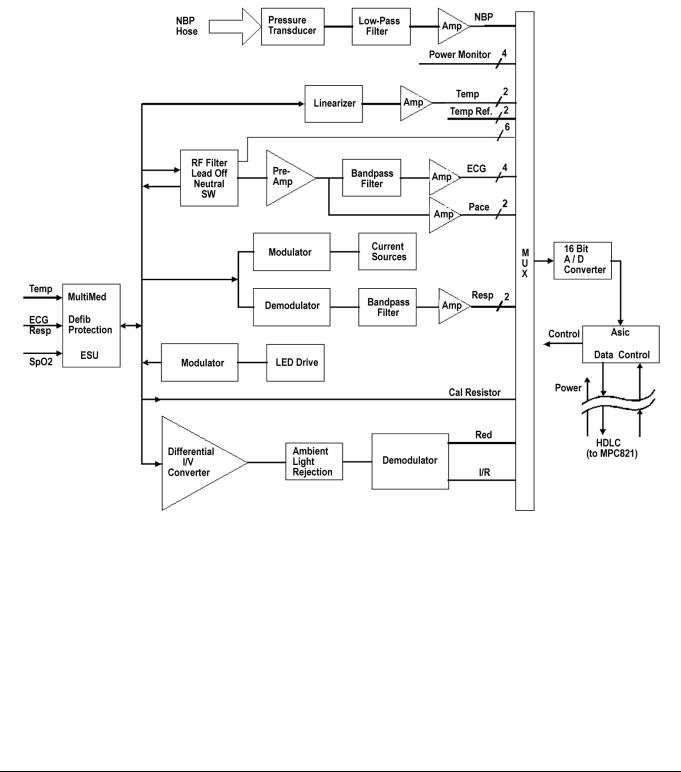
Figure 2 Front End
5Physiological Parameter Data Acquisition
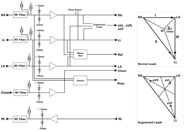
5.1ECG/Resp
Transducers gather physiological data at the patient and feed them into the small MultiMed Pod at the bed. The MultiMed Pod in turn is connected via a 3-meter cable to the front end in the main unit where analog ECG, Respiration, Temperature, and SpO2 signals are converted to digital form and sent through isolators for processing.
The MultiMed Pod located close to the patient accepts a set of 3, 5 or 6 shielded ECG electrode leads, an SpO2 (Nellcor) cable adapter, and a temperature sensor. The ECG section contains RF filters, and overvoltage clamps that include 1k series resistors to limit shunting of defibrillator current. The SpO2 and temperature sections also contain RF filters. Impedance respi-
18 |
Dräger Medical AG & Co. KGaA |
6013.053 |
Revision 0 Released |
All rights reserved. Copyright reserved. |
Gamma Gamma XL SM Function Description.fm 03.12.04 |

Gamma / Gamma XL Patient Monitor |
Function Description |
|
|
Gamma Gamma XL SM Function Description.fm 03.12.04 |
All rights reserved. Copyright reserved. |
5.1.1ECG
ration is sensed through the ECG electodes. Void-free potting and internal shielding enable compact containment of high voltage defibrillator and electrosurgery pulses. The small interconnecting cable to the main assembly is captive at the MultiMed POD but plugs into the MultiMed front end via a specially shielded connector.
The front end accepts physiological signals from the MultiMed POD connector and feeds temperature, respiration, and ECG signals via RF filters, configuration multiplexers, and pre-amplifiers to a high-speed multiplexer driving a 16-bit analog-to-digital (A/D) converter. The data stream is sent to the Main Processor board via an opto-isolator. Control commands from the Processor are sent out to the front end on a similar isolating link. Isolated DC power is also provided.
The ECG signals are conductively coupled to the isolated circuits via currentlimiting series resistors, whereas the SpO2 signals are optically isolated at the transducer. Temperature signals are doubly insulated at the patient by disposable boots on the sensors. AC (40kHz) excitation currents for respiration monitoring are dc-isolated by high-voltage ceramic capacitors.
The A/D samples the following parameters:
Table 1 Parameter Sampling Table
Parameter |
# of Channels |
|
|
ECG |
4 |
|
|
Pace |
2 |
|
|
SpO2 Red |
1 |
|
|
SpO2 IR |
1 |
|
|
NBP |
1 |
|
|
Resp |
1 |
|
|
Temp |
2 |
|
|
The hardware pace detector monitors the ECG signal in two of the four channels (those not connected to the chest leads). All other signals are decimated and filtered using digital signal processing in the MPC823E. High oversampling rate is required to minimize the requirements (and size) of the analog anti alias filters. Superior rejection to ESU and other types of interference is achieved with this type of design.
•Bandwidth is set flexibly by software filters.
•Reconfigurable neutral selector can drive any electrode.
•Lead-on detection functions with even poor electrodes.
•Calibration voltages can be superimposed on patient wave-forms or onto flat baselines.
See Figure 3. Composite electrocardiographic (ECG) signals generated by the heart and by a pacemaker are filtered to reduce RF interference from impedance respiration and electrosurgery and then injected with dc lead-off detection currents. Over-voltage clamps protect the semiconductors from the surges passing the spark gaps in the MultiMed Pod and also reduce the dc current applied to the patient due to a component fault.
Dräger Medical AG & Co. KGaA |
6013.053 |
Revision 0 Released |
19 |
Function Description |
Gamma / Gamma XL Patient Monitor |
|
|
Figure 3 Lead-Forming Network
5.1.2 |
Lead Selection |
A lead-forming network following the RF filter generates the necessary refer- |
|
|
ence points for electrocardiographic measurements. Both normal leads (I, II, |
|
|
III, V1 and V2) and augmented leads (aVL, avR, and avF) can be obtained. |
|
|
Four differential channels generate the main axes I, II, V1 and V2. The |
|
|
remaining leads are derived mathematically as indicated in the vector dia- |
|
|
gram of Figure 3. |
5.1.3 |
Lead-Off Detection |
Lead-off detection is accomplished by introducing a very small current into |
|
|
each patient electrode, which would drive the corresponding input high if it |
|
|
were disconnected. A set of five comparators detects a lead-off condition. |
5.1.4Low-Pass Filtering and The ECG preamplifier has a flat frequency response of 0.5 - 40Hz, with a
|
Common Mode |
software notch filter at 50/60 Hz. A 180° combined signal drives the neutral |
|
|
Enhancement |
electrode to increase the CMMR. |
|
5.2 |
Respiration |
Impedance respiration is monitored by injecting a 40 kHz square wave of cur- |
|
|
|
rent into the RA electrode. The resulting 40 kHz voltage drop between the RA |
|
|
|
+ LL electrodes is proportional to the impedance. Especially balanced true |
|
|
|
current sources do not load the ECG electrodes or distort the ECG morphol- |
|
|
|
ogy. The returning 40 kHz differential voltage is amplified, synchronously |
|
|
|
demodulated, and low-pass filtered. An AC-coupled stage with an “autobloc” |
|
|
|
DC restorer feeds the input to the A/D converter with a nominal output of 60 |
|
|
|
mV per Ohm. |
|
|
|
|
|
20 |
Dräger Medical AG & Co. KGaA |
6013.053 |
Revision 0 Released |
All rights reserved. Copyright reserved. |
Gamma Gamma XL SM Function Description.fm 03.12.04 |
Gamma / Gamma XL Patient Monitor |
Function Description |
|
|
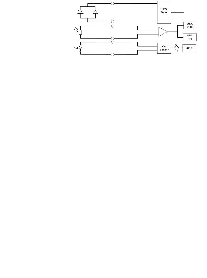
5.3SpO2
Gamma Gamma XL SM Function Description.fm 03.12.04 |
All rights reserved. Copyright reserved. |
|
Figure 4 SpO2 Functional Block Diagram |
|
The pulse oximeter circuit uses a Nellcor® sensor to detect the oxygen satu- |
|
ration level in arterial blood flow. Determination of the concentration of oxy- |
|
gen in the blood is based upon the principle that the absorption of red (R) |
|
light depends on the degree of oxygenation of the blood, whereas the absorp- |
|
tion of infrared (IR) radiation is relatively independent of oxygenation and |
|
causes only constant attenuation. See Figure 4. In the SpO2 sensor, R and |
|
IR light emitting diodes (LEDs) are alternately pulsed ON at a 25% duty cycle. |
|
The light is transmitted through a well-perfused part of the body, such as a |
|
fingertip or an ear lobe. The intensity of light (including ambient) transmitted |
|
through or scattered by the blood is converted to a current by a photodiode in |
|
the sensor. The current that appears when both LEDs are OFF depends |
|
mainly on the ambient light, which is later subtracted to leave only the R or IR |
|
signal levels. The large dynamic range of the light intensities requires con- |
|
stant automatic monitoring and adjustment. |
|
The intensities of the R and IR sources are independently controlled by two |
|
digital-to-analog converters (DACs) attenuating the 2.5 V reference. These |
|
levels or zero are sequentially selected by a multiplexer, and converted to a |
|
driving current which is further guided or inverted by an output multiplexer to |
|
the LEDs in the sensor. |
5.3.1 SpO2 Front End |
The primary purpose of the SpO2 front end is to convert the sensor’s analog |
|
signal into individual digitized signals for the red and infrared analog signals |
|
for processing by the microprocessor. See Figure 5. Circuitry in the front end |
|
first eliminates the non-pulsatile component in the input signal, then demulti- |
|
plexes the resulting pulsatile signal to separate the R and IR signal compo- |
|
nents, and finally converts the demultiplexed R and IR analog signals into |
|
serial digital data streams. |
Dräger Medical AG & Co. KGaA |
6013.053 |
Revision 0 Released |
21 |
Function Description |
Gamma / Gamma XL Patient Monitor |
|
|
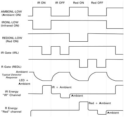
Figure 5 Sensor LED Timing Diagram
A sequence of light pulses, driven from the chopped current source in the sensor LEDs, are passed through a finger or an earlobe to a photodiode. The sensor LEDs are connected in an anti-parallel fashion on one pair of wires. A timing generator controls the sensor LEDs and signal multiplexing/ demultiplexing (see Figure 5) by means of three control signals:
|
|
• |
IRONL (infrared LED) |
|
|
|
• AMBONL (LEDS not lit) |
|
|
|
|
• |
REDONL (red LED) |
|
5.3.2 |
Input Stage |
A preamplifier converts the photocurrent to an equivalent voltage, and applies |
||
|
|
it to a 20 Hz high-pass filter that removes the non-pulsatile component. The |
||
|
|
output of the preamplifier is fed to a saturation detector. |
||
5.3.3 |
Brightness Control |
If the output of the preamplifier is in saturation, the gate array provides a sig- |
||
|
|
nal to the digital-to-analog converters (DACs), which controls the drive cur- |
||
|
|
rent to increase or decrease the brightness of the LEDs. |
||
|
|
Controlling LED brightness extends the system dynamic range. For a very |
||
|
|
transparent subject it may not be possible to reduce the gain to prevent satu- |
||
|
|
ration. In that event, the brightness must be reduced. An additional purpose is |
||
|
|
to equalize the received amplitude of each wavelength. If both LEDs are |
||
|
|
turned ON to maximum brightness, and the software finds an extraordinary |
||
|
|
difference between the two, the microprocessor tends to reduce that differ- |
||
|
|
ence by equalizing the R or IR brightness signals. |
||
|
|
|
|
|
22 |
Dräger Medical AG & Co. KGaA |
|
6013.053 |
Revision 0 Released |
All rights reserved. Copyright reserved. |
Gamma Gamma XL SM Function Description.fm 03.12.04 |
Gamma / Gamma XL Patient Monitor |
Function Description |
|
|
5.3.4Ambient Light Rejection The ambient rejection amplifier is a synchronous detector. The signal applied
Amplifier |
to its inverting input is a composite of R, IR, and ambient signals. The non- |
|
inverting input is the same signal gated by the timing generator. This synchro- |
|
nously multiplexes the IR, ambient, and R analog signals. |
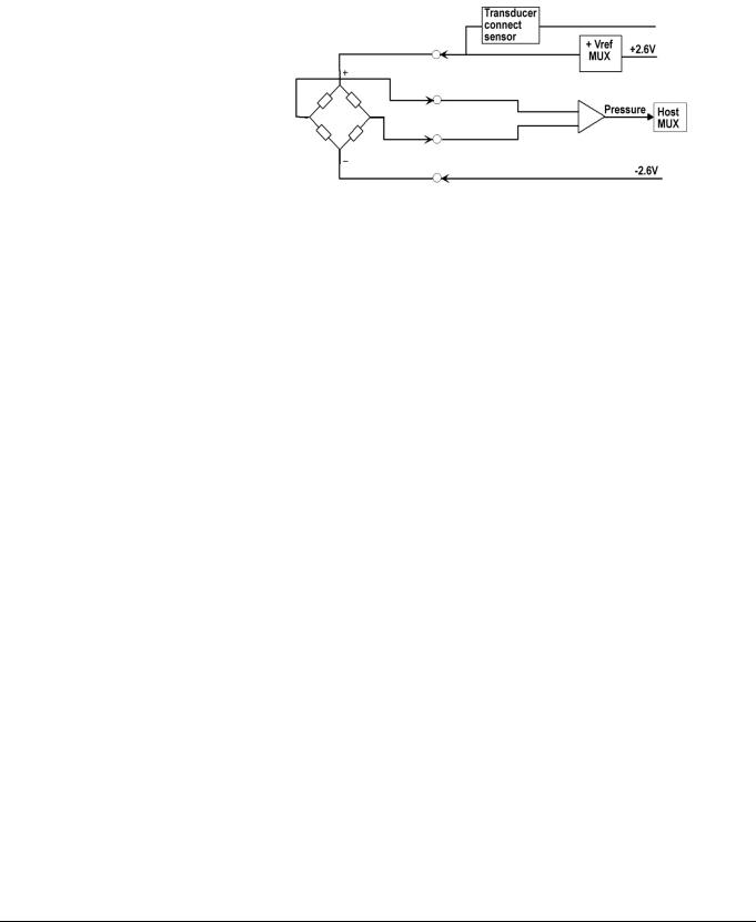
5.4Invasive Blood Pressure
Figure 6 IBP Functional Block Diagram
The IBP circuit has been designed to be used with a strain gauge pressure transducer. See Figure 6. The analog portion of the IBP circuit provides excitation voltages for resistance bridge transducers. These voltages are derived from a reference which is also used to derive the A/D converter reference voltage. At the circuit input, a resistor divider network provides for transducer unplugged detection. R-C filtering and protection diodes limit the effects produced during electrosurgery, defibrillation, and other such procedures. A selector multiplexer allows for the insertion of calibration signals into the amplifier stage. The multiplexor feeds the pressure signal to a buffer amplifier, which in turn feeds the AD converter analog input. This allows the monitor to measure pressure signals in a range greater than ±700 mmHg with a resolution of approximately .02mmHg/LSB.
When no pressure transducer is plugged into the monitor, the resistor divider network puts a negative signal into the instrumentation amplifier, which propagates through the system to indicate the unplugged condition.
Gamma Gamma XL SM Function Description.fm 03.12.04 |
All rights reserved. Copyright reserved. |
Dräger Medical AG & Co. KGaA |
6013.053 |
Revision 0 Released |
23 |
 Loading...