


Technical Documentation
Isolette® C2000/C2000e
Infant Incubator
WARNING!
Each servicing and/or testing of the device requires full understanding of this Technical Documentation. Carefully read the Instructions for Use prior to any use of the device.
Revision 1.1 6016.036 9036214
Because you care

K6016036IECIVZ.fm 21.05.07 |
Copyright reserved. |
Contents
General
1 |
Symbols and Definitions |
3 |
2 |
Notes |
3 |
Function Description
1 |
Controller Assembly |
7 |
||
2 |
Variable Height Adjustable Pedestal/Stand Assembly |
8 |
||
3 |
Hood/Shell Assembly |
9 |
||
4 |
Theory of Operation |
9 |
||
|
4.1 |
Electrical System .................................................................................................................... |
9 |
|
|
|
4.1.1 |
Sensor Module ......................................................................................................... |
9 |
|
|
4.1.2 |
Controller ................................................................................................................ |
13 |
|
|
4.1.3 Impeller Movement Detector (IMD) P.C. Board ...................................................... |
14 |
|
|
|
4.1.4 |
Fan Motor ............................................................................................................... |
14 |
|
|
4.1.5 |
Heater Power ......................................................................................................... |
14 |
|
|
4.1.6 |
Humidity Heater Power .......................................................................................... |
15 |
|
4.2 |
Air System ............................................................................................................................ |
18 |
|
|
|
4.2.1 |
Overall Functional Description ............................................................................... |
18 |
|
|
4.2.2 |
Air Mode ................................................................................................................. |
19 |
|
|
4.2.3 |
Skin Mode .............................................................................................................. |
19 |
|
|
4.2.4 |
Oxygen Control ...................................................................................................... |
20 |
|
|
4.2.5 |
Humidity Control Valve ........................................................................................... |
20 |
|
4.3 |
Hardware .............................................................................................................................. |
20 |
|
|
|
4.3.1 |
Weighing Mode ....................................................................................................... |
20 |
|
|
4.3.2 |
Trend Displays ........................................................................................................ |
20 |
|
|
4.3.3 |
Interface Connections ............................................................................................ |
21 |
I

Contents
4.3.4 RS-232 Serial Port Protocol .................................................................................... |
21 |
Maintenance Procedures
1 |
Air filter |
|
27 |
|
|
1.1 |
Safety precautions ................................................................................................................ |
27 |
|
|
1.2 |
Replacing the air filter ........................................................................................................... |
28 |
|
1 |
Oxygen sensors |
31 |
||
|
1.1 |
Notes/Safety instructions ...................................................................................................... |
31 |
|
|
1.2 |
Replacing the oxygen sensors ............................................................................................. |
32 |
|
|
|
1.2.1 |
Service Equipment Required .................................................................................. |
32 |
|
|
1.2.2 |
Procedure ............................................................................................................... |
32 |
|
1.3 |
Calibrating the oxygen sensors ............................................................................................ |
40 |
|
|
|
1.3.1 Safety instructions for calibrating the oxygen sensors ............................................ |
40 |
|
|
|
1.3.2 |
General ................................................................................................................... |
40 |
|
|
1.3.3 |
21 vol.%O2 calibration ............................................................................................ |
41 |
|
|
1.3.4 |
100 vol.%O2 calibration .......................................................................................... |
43 |
Block diagrams
1 |
Shell Assembly Cable Routing (1) |
49 |
2 |
Scale Assembly Cable Routing (2) |
50 |
Annex
Parts catalog
Test List
Copyright reserved. |
K6016036IECIVZ.fm 21.05.07 |
II

General
1

2

4.0 Printed on 21.05.07 K General.fm |
Copyright reserved. |
Isolette® C2000/C2000e |
General |
|
|
1Symbols and Definitions
WARNING
A WARNING statement provides important information about a potentially hazardous situation which, if not avoided, could result in death or serious injury.
CAUTION
A CAUTION statement provides important information about a potentially hazardous situation which, if not avoided, may result in minor or moderate injury to the user or patient or in damage to the equipment or other property.
NOTE
A NOTE provides additional information intended to avoid inconvenience during operation or servicing of the equipment.
Definitions according to German standard DIN 31051:
Inspection |
= examination of actual condition |
|
Maintenance |
= measures to maintain specified condition |
|
Repair |
= |
measures to restore specified condition |
Servicing |
= |
inspection, maintenance, and repair |
2 |
Notes |
This Technical Documentation conforms to the IEC 60601-1 standard. |
Read each step in every procedure thoroughly before beginning any test. Always use the proper tools and specified test equipment. If you deviate from the instructions and/or recommendations in this Technical Documentation, the equipment may operate improperly or unsafely, or the equipment could be damaged.
Dräger recommends that only Dräger provided parts be used for maintenance. Otherwise the correct functioning of the device may be compromised.
The maintenance procedures described in this Technical Documentation may be performed by trained service personnel only. These maintenance procedures do not replace inspections and servicing by the manufacturer.
This Technical Documentation is for the purpose of information only. Product descriptions found in this Technical Documentation are in no way a substitute for reading and studying the Instructions for Use.
NOTE
Unless otherwise stated, reference is made to laws, regulations or standards (as amended) applicable in the Federal Republic of Germany for equipment used or serviced in Germany. Users or technicians in all other countries must verify compliance with local laws or applicable international standards.
6016.036 |
3 |

4 |
General |
036.6016 |
C2000/C2000e Isolette® |
|
Copyright reserved. |
4.0_Printed on_21.05.07_K_General.fm

Function Description
5

6
Isolette® C2000/C2000e |
Theory of Operation |
|
|
1Controller Assembly
Figure 1 Controller Assembly Block Diagram
2.0 Printed on 21.05.07 F6016036 Theory of Operation.fm |
Copyright reserved. |
6016.036 |
7 |
Theory of Operation |
Isolette® C2000/C2000e |
|
|
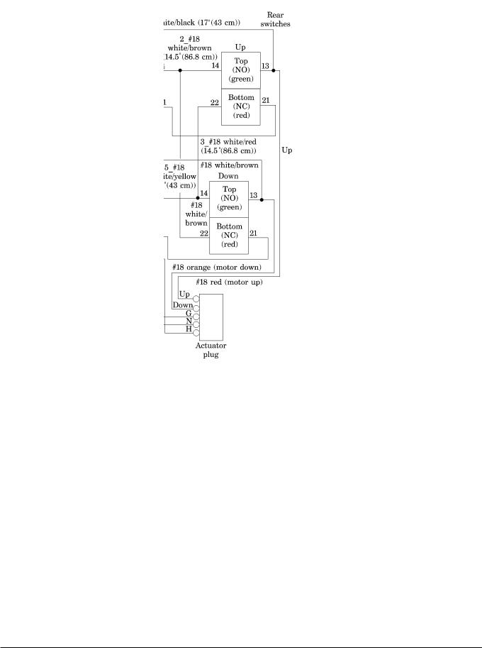
2Variable Height Adjustable Pedestal/Stand Assembly
Figure 2 Variable Height Adjustable Pedestal/Stand Assembly Wiring Dia-
gram
|
of Operation.fm |
Copyright reserved. |
2.0 Printed on 21.05.07 F6016036 Theory_ |
8 |
6016.036 |
Isolette® C2000/C2000e |
Theory of Operation |
|
|
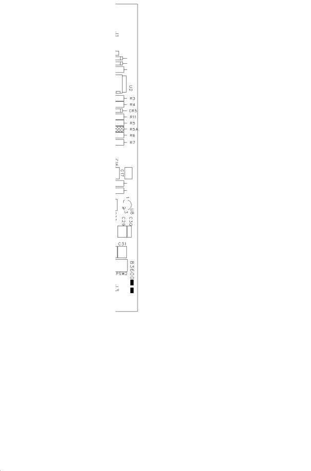
3Hood/Shell Assembly
|
|
|
|
Figure 3 Scale P.C. Board Layout |
|
Operation.fm |
4 |
Theory of Operation |
|
|
|
4.1 |
Electrical System |
|
|
||
of_ |
|
|
|
|
|
Theory |
4.1.1 |
Sensor Module |
The sensor module P.C. board provides the interface for the patient and incu- |
||
|
|||||
F601603621.05.07onPrinted2.0 |
reserved.Copyright |
|
bator requirements that the infant incubator must support. The sensor module |
||
|
assembly reads and processes the following parameters: |
||||
|
|
|
|
||
|
|
|
|
• |
Temperature |
|
|
|
|
• |
Oxygen |
|
|
|
|
• |
Humidity |
|
|
|
|
• Weight information, collected from external sensors and cables |
|
|
|
|
|
|
|
|
6016.036 |
|
|
9 |
|

Theory of Operation |
Isolette® C2000/C2000e |
|
|
This information is periodically updated and transmitted to the main controller upon request.
The sensor module P.C. board does not require manual calibration. To provide safe monitoring and control, both the temperature information and oxygen information have redundant circuitry to prevent single-fault failures.
All signals are transmitted through serial data communication.
The sensor module connects to a sensor P.C. board that has the following parameters required for the system:
•Air temperature
•Oxygen
•Humidity
•Fan operation
Power Supply
The power to the sensor module P.C. board is provided through connector J4, providing ±12 V AC for the system. U21, U19, and U15 regulate the voltages by providing +5 V, digital +5 V and analog -5 V, respectively. U20 provides a precision +5 V source for analog signal conversions.
Sensor Position Detection
Hall effect sensors sense the magnets in the slide mechanism. The sensors, U9 and U2, determine the calibration position. The sensors, U16 and U22, determine the hood’s position during normal operation. The output is normally high. These devices provide a low output if a significant south pole magnetic field is applied to their surface.
Remote Light Alarm Indicator
DS1 provides an alarm indication with a high field of view. A positive signal,
RMLITE, at the gate of transistor Q3 illuminates DS1.
Scale Interface
The connector J3 provides the interface and power for the scale module. The scale module supports serial data communication. The signal SCCLK is used for scale communication only and is normally high when the scale is disconnected. The signal CDATA is bi-directional and is normally in the low state when the scale is not connected.
Fan Control/Feedback Circuit
To drive the DC fan on the sensor board, the signal FANON pulses Q1 on its gate at a 50% duty cycle at approximately 48 Hz to maintain proper speed and to increase fan life. Every 4 seconds, the microcontroller asserts FANON for 42 milliseconds, and the fan pulse detection begins.
U1A handles the pulse detection and, through the resistors R3 and R7, samples the current spikes from the fan produced across R1. The amplifier operates as a differentiator, providing high gain for the current spikes. D1 and C16
10 |
6016.036 |
|
of Operation.fm |
Copyright reserved. |
2.0 Printed on 21.05.07 F6016036 Theory_ |

2.0 Printed on 21.05.07 F6016036 Theory of Operation.fm |
Copyright reserved. |
Isolette® C2000/C2000e |
Theory of Operation |
|
|
then rectify and filter this signal and then feed it to the Analog/Digital (A/D) converter as signal FANPUL. This provides a semi-DC level as a function of the fan rotation.
Temperature Measurement
The temperature data acquisition circuit starts with the analog multiplexers, U6 and U5, each allowing an 8-to-1 signal switching. The microcontroller selects the multiplexer channel by the signals MSEL0, MSEL1, and MSEL2. Each multiplexer output can be inhibited by either signal TM1SEL or TM2SEL, depending on the multiplexer; only one multiplexer is active at a time. With each multiplexer output into the amplification under control, this data acquisition is viewed as a 16-to-1 analog temperature selector. The microcontroller selects a new temperature channel every 21 milliseconds.
The resistor R14 provides the constant voltage drive required for each thermistor as it is selected from the appropriate multiplexer. This voltage is amplified by a factor of 2.1083, and is sent to the A/D converter as signal TCOM.
To provide automatic calibration of the circuit and eliminate temperature and aging drifts, R44 and R45 introduce precise calibration values into each multiplexer. These values are read through the multiplexers and are used in software processing to eliminate the gain and offset errors of each multiplexer/amplifier combination. These values equate to 120.87 °F
(49.37 °C) and 72.72 °F (22.62 °C), which allow for precise circuit calibration.
Resistor R43 is an additional check to the circuit, which provides a resistance simulating 98.57 °F (36.98 °C).
The sensor module supports the following three air temperature sensors on the sensor board:
•AIRTE
•AIRTC
•AIRTM
These signals interface through J2-6 to J2-8. The thermistors then route to temperature multiplexers U5 and U6, which provide analog signal processing into the A/D converter.
The skin temperature probes contain dual thermistors. The sensor module supports two probes that plug into connectors J6 and J7. The two thermistors connect to SKNT1M and SKNT1C or SKNT2M and SKNT2C, with a common connector at AGND. Both probes have high frequency filtering by inductor networks LN1 and LN2. In addition, each skin probe has a resistor that is input to the multiplexers. The microcontroller uses these signals, SKNT1D and SKNT2D, to determine if the probes are installed.
Humidity Measurement
Humidity measurement originates with the humidity sensor on the sensor P.C. board, connected to J2-5 and J2-14 (AGND and HS2, respectively). The sensor is a capacitive-type that changes capacitance as a function of humidity; the net range of capacitances is from approximately 160 pF to 200 pF. The sensor connects to the amplifier U7A/U8A, which is set up as a multivibrator. The sensor capacitance charges up through R20 and R21 to a threshold voltage established by R30 and R26.
6016.036 |
11 |

Theory of Operation |
Isolette® C2000/C2000e |
|
|
When the capacitor voltage reaches the threshold, the capacitor U7A/U8A goes high to 2.5 V as controlled by R19 and R28, and turns on Q2. This discharges the humidity sensor through R20 until it reaches the lower threshold established by R24, R26, and R30. The capacitor voltage goes from approximately 0.2 V to 0.7 V. At this point, the comparators output goes low, releasing the drive to Q2 and allowing the humidity to start charging again. This produces a frequency output as a function of capacitance, such as humidity.
The output signal, which is only 2.5 V peak, is then input into U7B/U8B to condition the 5 V signal. Hysteresis is provided through the use of R23, R29, and R32 to ensure stable frequency switching. The output signal, JUMPUL, is then sent to the microcontroller for processing. A typical frequency would be around 37 KHz.
Microcontroller
The microcontroller is a Priority-Interrupt Controller (PIC) 16C73, used for signal-processing and for control of all signals on the sensor module. The device has three external ports, configurable as inputs and outputs. The microcontroller operates from a precise time-base of crystal Y1, operating at 4 MHz. The instruction cycle time of the PIC is ¼ of that, namely at 1 MHz or 1 microsecond.
To ensure a clean power-up, U10 provides a fixed power-up reset to the microcontroller. This integrated circuit also generates a rest in the event of a brownout condition when the D+5 falls below a predetermined threshold.
If the main controller determines that the sensor module requires reset intervention, the reset line of the microcontroller, SMRES, is available to the main controller.
The PIC device operates with an internal watchdog timer device that asserts
SMRES if the program execution operates outside normal conditions.
Expansion Devices
The digital multiplexer, U3, allows additional digital signals for processor control. It is a dual, 4-to-1 multiplexer that allows the microcontroller to use two ports for 8-bits of information. The signals, DVSEL0 and DVSEL1, control U18.
The buffered line-drivers, U13A/B and U14A, are used for signals that are going off-board, namely SMDATA, SCDATA, and SCCLK. The SMDATA line is used as a bi-directional line that can change from input or output “on-the- fly” for data communication to the main controller. The SCDATA is similar, with connection to the scale at connector J3. SCCLK is the buffered clock line used for scale communications.
Buffer U14B provides an inversion for TM1SEL, producing TM2SEL to alternately enable and disable the temperature multiplexers.
Analog/Digital (A/D) Conversions
The A/D converter, U11, is an eight-channel, 12-bit, serial, interface device. Control for the channels is software-configurable by the serial communication line SSPCLK, ADCDIN, and COMOUT. The signal, ACENI, enables the A/D converter for signal processing and is asserted twice every 21 milliseconds;
12 |
6016.036 |
|
of Operation.fm |
Copyright reserved. |
2.0 Printed on 21.05.07 F6016036 Theory_ |

Isolette® C2000/C2000e |
Theory of Operation |
|
|
4.1.2Controller
2.0 Printed on 21.05.07 F6016036 Theory of Operation.fm |
Copyright reserved. |
6016.036
the A/D converter is read twice. In addition, the ADCIN and COMOUT are driven at 21 millisecond intervals. The SSPCLK is shared with the EEPROM on the sensor board and scale clock; therefore, the timing is not periodic.
All temperature information appears as a multiplexed signal on Channel 0, and oxygen information appears as a multiplexed signal on Channel 2. Channel 4 enables the A/D converter to read its maximum input, and Channel 5 enables the A/D converter to read its minimum input to determine proper A/D functioning.
The analog representation of fan pulses apply to Channel 6.
The controller accepts input voltages between the range of 90 V AC and 264 V AC through a universal input switching power supply. Voltages above the safe operating range are clamped using a transorb diode.
The controller accepts input frequencies between the range of 48 Hz to 62 Hz through a universal input switching power supply.
The stand supplies the input power and protective ground to the controller and incorporates a 15 A circuit breaker and electromagnetic interference (EMI) filtering components.
The controller provides AC power to the heater and the humidifier. These outputs are fused in the controller to protect the controller in the event of a short circuit or electrical overload.
•Maximum heater voltage—264 V AC
•Maximum heater current—4.8 A
•Maximum humidifier voltage—264 V AC
•Maximum heater current—1.2 A
•Heater/humidifier fuse rating—6.3 A
The controller provides DC power to the following:
•The fan
•The sensor module
•The scale
•The SPO2 module, if available
•The airflow sensors
•The door switches
These outputs are current-limited in the controller to protect the controller and the powered device if a circuit shorts or electrically overloads. These outputs are regulated to ensure the output voltage is within the voltage specification for the powered device. The microprocessor feeds and monitors the outputs 1 and 2 into the A/D converter.
13

Theory of Operation |
Isolette® C2000/C2000e |
|
|
4.1.3 |
Impeller Movement |
The Impeller Movement Detector (IMD) P.C. board is positioned so that mag- |
|
Detector (IMD) P.C. |
nets pressed into the bottom of the impeller pass directly over a Hall effect |
|
Board |
sensor mounted to the IMD P.C. board. The IMD circuit monitors the Hall |
|
|
effect sensor’s pulse train, produced by the magnets when the impeller |
|
|
rotates. The speed of the impeller is measured and compared with the pre- |
|
|
determined maximum and minimum acceptance limits. If the impeller’s rota- |
|
|
tional speed is too fast or too slow, an impeller error signal generates. The |
|
|
IMD circuit also detects if one, two, or all three magnets are missing or if an |
|
|
old impeller without magnets is used. These errors produce the same error |
|
|
signal to the controller as for low or high impeller speeds. |
|
|
The controller’s +12 V supplies the power for the IMD circuit through a 301 Ω |
|
|
resistor. This resistor and the load of the IMD circuit form a voltage divider |
|
|
that sets the LONG signal voltage that remains constant. U1, a voltage regu- |
|
|
lator, supplies +5 V DC to the Hall effect sensor (U3) and the microcontroller |
|
|
(U2). As the magnets pass above the Hall effect sensor, its open-drain out- |
|
|
put, U3-2, goes low, detecting the magnets’ field. When the magnets’ field is |
|
|
removed, the oscillator is used as a reference. When an error condition is |
|
|
detected, U2-2, the microcontroller’s output, drives low, which accomplishes |
|
|
the following: |
|
|
• Turns off Q1. |
|
|
• Releases a portion of the load on the short signal, allowing it to rise above |
|
|
the LONG signal voltage. |
|
|
R2, the switch portion of the SHORT signal load, and R4, the unswitch posi- |
|
|
tion of the SHORT signal load, adjust to provide an approximate 1V swing |
|
|
between the error and non-error outputs. The capacitors, C1 and C2, filter the |
|
|
system’s supply. |
|
|
The IMD P.C. board supports in-circuit programming (ICP) of the microcon- |
|
|
troller. Programming is done after the unprogrammed microcontroller is popu- |
|
|
lated with all the other components by connecting a programmer to the pads |
|
|
labeled VPP, +5 V, CLK, DTA, and GND. |
4.1.4 |
Fan Motor |
The controller sets the fan motor speed if the watchdog is not tripped. The |
|
|
microprocessor supplies a pulse-width modulation (PWM) signal to an opto- |
|
|
coupler for isolation. The output connects to an integrator circuit that converts |
|
|
the PWM signal to an analog signal for the motor controller. The motor incor- |
|
|
porates the Hall effect sensors for monitoring and control. One of the Hall |
|
|
effect sensor outputs is fed to the microprocessor for measuring the motor |
|
|
speed. If the watchdog timer trips, the fan motor speed is maintained at |
|
|
1500 rpm ± 450 rpm. |
|
|
The controller provides an alarm to indicate a failure of the fan to rotate. |
|
|
When this occurs, the heater and humidifier disable, and an audible alarm |
|
|
with a visual indication activates. |
4.1.5 |
Heater Power |
The controller monitors the heater power. A current transformer is in series |
|
|
with the power to the heater and the humidifier. The output of the current |
|
|
transformer connects to the A/D converter. |
|
|
The system enables control of the incubator’s heater. The microprocessor |
|
|
controls a solid state relay that controls the power to the heater. The micro- |
|
|
processor and the watchdog circuit control the safety relay, K3. The release |
|
|
of the safety relay removes power from the heater regardless of the function- |
|
|
ality of the heater triac. |
|
|
|
14 |
|
6016.036 |
|
of Operation.fm |
Copyright reserved. |
2.0 Printed on 21.05.07 F6016036 Theory_ |

2.0 Printed on 21.05.07 F6016036 Theory of Operation.fm |
Copyright reserved. |
Isolette® C2000/C2000e |
Theory of Operation |
|
|
4.1.6Humidity Heater Power The controller monitors the humidity heater power. A current transformer is in
series with the power to the heater and humidifier. The output of the current transformer connects to the A/D converter.
The system enables control of the humidity heater. The microprocessor controls a solid state relay that controls the power to the humidity heater. The microprocessor and the watchdog circuit control the safety relay, K3. The release of the safety relay removes power from the humidifier heater regardless of the functionality of the humidity heater triac.
Oxygen Control
The system enables control of the oxygen pneumatics. The microprocessor provides a PWM signal to the solenoid’s metal oxide semiconductor fieldeffect transistor (MOSFET).
The voltage to the oxygen solenoid is monitored and fed into the A/D converter. This circuit monitors the 12 V power supply and thermal fuse.
Light-Emitting Diodes (LEDs)
The microprocessor drives each light-emitting diode (LED). The hardware watchdog timer circuit drives the alarm/system fail indicator. The power fail detection circuitry drives the Power Fail indicator.
Audio Alarms
The audible alarm circuit incorporates an oscillator circuit to generate the three alarm frequencies used:
•600 Hz
•1500 Hz
•2500 Hz
The microprocessor, the watchdog circuit, and the power failure detection circuitry drive the audible alarm circuit.
The audio volume is capable of three discrete sound levels. An analog switch, incorporated in the audible alarm amplifier circuit, selects a 57 dB, 62 dB, or 65 dB output, as measured by International Electrotechnical Commission (IEC) 601-19-2:102.3. The microprocessor, the watchdog circuit, and the power failure detection circuit control the analog switch.
Power Fail
The controller provides an audio output for power fail conditions. The alarm oscillator is set for 600 Hz at 65 dB output, as measured by IEC 601-19- 2:102.3. A timer circuit generates the cadence tone during power failures.
When a Power Failure alarm is activated, the following occurs:
•The Power Fail indicator on the front panel illuminates.
•An alarm sounds.
A high energy storage capacitor powers the power failure detection circuitry and supplies power to the audible alarm and indicator for a minimum of 10 minutes. This capacitor charges while the unit is operating. When power is
6016.036 |
15 |

Theory of Operation |
Isolette® C2000/C2000e |
|
|
lost to the controller and the Power switch remains in the On position, the storage capacitor supplies power to the power failure circuitry. The power failure circuitry incorporates a timer circuit that periodically enables the audible alarm and Power Fail indicator at a cadence of 520 milliseconds off and 98 milliseconds on until one of the following occurs:
•The Power switch is turned off.
•The power is restored.
•The storage capacitor is depleted.
The Power Failure alarm silence is hardware-controlled. Pressing the Alarm Silence key during power failure silences the alarm for the duration of the power failure. The Power Fail indicator flashes until one of the following occurs:
•The storage capacitor is depleted.
•The Power switch is turned off.
•The power is restored.
The System Failure alarm is unaffected by the Alarm Silence key.
Interfacing
An interface port enables an RS-232 serial communication link. The serial port is fully isolated from the remaining controller circuitry. The power to the serial port interface circuitry derives from an isolated winding on the power supply transformer. The RS-232 interface connector is a female DB-9, mounted on the rear of the controller. An RS-232 transceiver converts the RS-232 to logic voltage levels and vice versa. Optocouplers provide the isolation barrier and interface the RS-232 transceiver to the PC16550 UART. The UART interfaces the serial port to the microprocessor bus. All lines connected to the RS-232 connector are filtered to block EMI. The RS-232 transceiver incorporates electrostatic discharge (ESD) protection.
An interface enables communication between the controller module and the sensor module. The sensor module interface connector is a female DB-9, mounted on the rear of the controller and comprised of a bi-directional data line, a clock output line, and a reset output line. The data lines are fully isolated and optocoupled to the microprocessor. The controller provides isolated power to the sensor module.
Door Switches
The controller connects to the two door switches that are wired in parallel.
The controller performs the following:
•Provides no more than 5 milliamperes (mA) of current to the switches
•Provides less than 6 V of power to the switches
•Monitors the return current to determine if either door is open
The switches are open when the door is closed. The input is protected with transorb diodes and is filtered to block EMI and prevent ESD damage to the controller.
16 |
6016.036 |
|
of Operation.fm |
Copyright reserved. |
2.0 Printed on 21.05.07 F6016036 Theory_ |
2.0 Printed on 21.05.07 F6016036 Theory of Operation.fm |
Copyright reserved. |
Isolette® C2000/C2000e |
Theory of Operation |
|
|
Cooling Fan
The cooling fan provides a continuous flow of air through the controller to remove heat generated by the various components inside the controller enclosure. The cooling fan operates whenever power is applied to the controller. The cooling fan is equipped with a tachometer output signal that is supplied to the microprocessor.
Ambient Temperature Sensors
The temperature sensors, located in the airflow of the cooling fan, are NTC thermistors. The output signals of the redundant sensors feed into the A/D converter.
Watchdogs
The first watchdog timer is internal to the microprocessor. If the software does not update the watchdog timer within the required time frame, the internal watchdog resets the microprocessor and all peripherals connected to the external reset line.
The second watchdog timer circuit attaches to the microprocessor bus. The microprocessor continuously writes the following data to the watchdog timer:
•Data 55 hex (01010101 binary) to watchdog register #1.
•Data AA hex (10101010 binary) to watchdog register #2.
The watchdog timer trips in 1 second ±0.4 second unless the above sequence is completed. Once the watchdog timer trips, the following occurs:
•The safety relay turns off, removing power from the heater and the humidifier.
•The fan control reverts to closed loop control, maintaining a constant fan speed regardless of the door’s position.
•The oxygen solenoid control from the microprocessor is overridden, and the oxygen solenoid turns off so that no oxygen enters the hood.
•A constant alarm sounds for a minimum of 500 milliseconds.
•The system failure indicator illuminates.
The microprocessor resets the watchdog timer after a watchdog trip by sending the above data sequence.
Factory Defaults
Factory defaults are stored in program memory, flash EEPROM. System parameters are configured and stored in the real time clock (RTC) module or serial EEPROM. The RTC memory and random access memory (RAM) are protected against corruption during power failures and are battery-backed for a period of time.
The program is stored in reprogrammable memory and may be reprogrammed through a cable connected to the serial port of a computer. The program memory is stored in a flash EEPROM. The RS-232 serial port operates at speeds of 115,200 baud to expedite the speed of the program download.
6016.036 |
17 |
Theory of Operation |
Isolette® C2000/C2000e |
|
|
|
|
|
|
Power Supply |
|
|
The power supply is so designed that 1 second after disconnection of the |
|
|
plug, the voltage between the supply pins of the plug and between either sup- |
|
|
ply pin and the enclosure does not exceed 60 V by using a bleeder resistor |
|
|
across the mains filter capacitor, if necessary. |
4.2 |
Air System |
|
4.2.1 |
Overall Functional |
The controller displays the air temperature and the skin temperature on an |
|
Description |
electroluminescent display. Optional displays of the humidity and oxygen |
|
|
concentration levels within the hood environment and the infant’s weight are |
|
|
available. In addition, Trend displays of 2, 4, 8, 12, and 24 hours of all param- |
|
|
eters (except weight, which is presented in days) are user-selectable. |
To indicate which mode of operation, Air Mode or Skin Mode, is in control, the set temperature of the controlling parameter remains on adjacent to the actual displayed temperature. In addition, the rotating wheel in the Air or Skin softkey designator rotates.
The forced air circulation system controls the temperature, humidity, and oxygen concentration (see Figure 4). The motor-driven impeller in the shell draws a controlled amount of approximately 7 liters per minute (lpm) of room air through the air intake filter.
Figure 4 Air/Oxygen Circulation System
18
|
of Operation.fm |
Copyright reserved. |
2.0 Printed on 21.05.07 F6016036 Theory_ |
6016.036

2.0 Printed on 21.05.07 F6016036 Theory of Operation.fm |
Copyright reserved. |
Isolette® C2000/C2000e |
Theory of Operation |
|
|
|
|
|
|
|
|
The impeller also provides the internal circulation at a much greater flow than |
|
|
|
that of the fresh gas inflow. The total flow of fresh and circulated air is |
|
|
|
directed past the airflow sensor and around the heater. The air enters the |
|
|
|
infant compartment up through the slots at the front and rear of the main deck |
|
|
|
and then passes between the front and rear inner walls. The air circulates |
|
|
|
past the sensor module, which contains the temperature sensing probe that |
|
|
|
encapsulates the air temperature control thermistor and a high air tempera- |
|
|
|
ture alarm thermistor. After circulating within the infant compartment, the air |
|
|
|
then re-circulates down through a slot in the right end of the main deck, and |
|
|
|
back to the impeller. When the access panel of the hood is open, the air con- |
|
|
|
tinues to flow upward past the opening, Impeller ramps up to 2200 RPM to |
|
|
|
creating a warm air curtain to minimize the drop in air temperature in the incu- |
|
|
|
bator. The temperature is regulated using either the incubator’s air or the |
|
|
|
infant’s skin temperature as the controlling parameter; the desired mode is |
|
|
|
selected by the front panel keys. |
|
|
|
In either mode of operation, the heater output is proportional to the amount of |
|
|
|
heat required to maintain the desired temperature. |
|
4.2.2 |
Air Mode |
In Air Mode, the air temperature is maintained from 68 °F to 99 °F (20 °C to |
|
|
|
37 °C) (99 °F to 102 °F (37 °C to 39 °C) in Temperature Override Mode), as |
|
|
|
selected by the Air Set Temperature Up and Down arrow keys on the front |
|
|
|
panel. A probe located in the sensor module monitors the incubator’s air tem- |
|
|
|
perature and compares it with the air’s set temperature setting. The probe |
|
|
|
supplies this information to the heater control circuitry, which regulates the |
|
|
|
heater output to maintain the air temperature setting. The actual air tempera- |
|
|
|
ture appears on the Air Temperature display. A second sensor within the air |
|
|
|
temperature probe serves as a backup to limit the maximum incubator tem- |
|
|
|
perature. If the high temperature limit activates, the heater shuts off. |
|
|
|
In Air Mode, the infant’s temperature is a function of the air temperature and |
|
|
|
the infant’s ability to establish and maintain its own temperature. A small |
|
|
|
infant, or one with underdeveloped homeostatic control, may not be able to |
|
|
|
maintain a stable temperature at the desired level. |
|
|
|
In Air Mode, there is a 15-minute setpoint retention. When you first power the |
|
|
|
unit on, the air setpoint temperature is 95 °F (35 °C); for example, if you |
|
|
|
change the air setpoint temperature to 95.9 °F (35.5 °C), and a power failure |
|
|
|
occurs, the air set temperature comes up to 95.9 °F (35.5 °C) if the unit turns |
|
|
|
on again before 15 minutes elapse. |
|
4.2.3 |
Skin Mode |
In Skin Mode, the infant’s temperature is selected from 93 °F to 99 °F (34°C |
|
|
|
to 37 °C) (99 °F to 100 °F (37 °C to 38 °C) in Temperature Override Mode) by |
|
|
|
the Skin Set Temperature Up and Down arrow keys on the front panel. A |
|
|
|
temperature sensing probe attaches directly to the infant’s skin. The probe |
|
|
|
supplies information to the heater control circuitry, which proportions the hea- |
|
|
|
ter output to maintain the skin set temperature. |
|
|
|
The air temperature still appears in Skin Mode, but as information only. If Air |
|
|
|
Mode is selected while the skin probe remains connected, the Skin Tempe- |
|
|
|
rature display continues to display actual skin temperature, but it does not |
|
|
|
control. |
|
|
|
The sensor module accepts two skin probes. However, when the second skin |
|
|
|
probe connects to the sensor module in Skin Mode, an alarm sounds, and the |
|
|
|
message Remove Skin 2 Probe appears. To connect the second skin probe, |
|
|
|
first select Air Mode. The controller then displays the two temperatures. |
|
|
|
|
|
6016.036 |
|
19 |
|

Theory of Operation |
Isolette® C2000/C2000e |
|
|
|
If Skin Probe 1 disconnects from its receptacle during Skin Mode, the Skin |
|
Temperature display goes blank, an alarm sounds, and the heater turns off. |
4.2.4 Oxygen Control |
An oxygen sensor assembly mounted inside the sensor module adjusts the |
|
flow of oxygen into the hood and controls the oxygen concentration level |
|
within the incubator’s hood environment. |
|
A valve regulates the flow into the incubator and periodically interrupts the |
|
flow of oxygen into the incubator. |
|
The sensor module houses two independent oxygen fuel cells that monitor |
|
and control the oxygen concentration levels inside the incubator. |
|
If the sensor module is outside of the hood environment during Oxygen |
|
Mode, audible and visual alarms are enabled, and the flow of oxygen is inter- |
|
rupted. |
|
In Oxygen Mode, the user sets the oxygen level control point from 21% to |
|
65%. The high and low alarm limits automatically set to ±3% from the control |
|
point. If the oxygen concentration level rises above or falls below the selected |
|
setpoint limits, an audible and visual alarm occurs. |
4.2.5Humidity Control Valve The built-in humidifier provides humidification of the incubator from 30% to
95% RH in 1% increments. The humidifier reservoir permits visual inspection of the water level.
|
|
If the water level in the chamber is depleted, an audible and visual Low |
|
|
|
Humidity alarm occurs, indicating a need to replenish the water supply. |
|
4.3 |
Hardware |
|
|
4.3.1 |
Weighing Mode |
Two load cells in a platform under the mattress perform the actual weighing |
|
|
|
function. These cells provide a voltage that is proportional to the load on it. |
|
|
|
The controller processes the voltage and displays it in either kilograms or |
|
|
|
pounds/ounces on the Weight display. |
|
|
|
The weighing routine is initiated by placing the infant on the mattress. If the |
|
|
|
infant is already on the mattress, lift the infant off the mattress; when the sys- |
|
|
|
tem zeros, return the infant to the mattress to obtain the weight. |
|
|
|
The Weigh key enables repeated weighing of the infant after the weighing |
|
|
|
routine is initiated as described above. |
|
4.3.2 |
Trend Displays |
Four standard parameters are presented on Trend displays: |
|
|
|
• |
Air temperature |
|
|
• |
Skin temperature #1 |
|
|
• |
Skin temperature #2 |
|
|
• |
Heater power |
Additional Trend displays are available when the unit is equipped with any of the following options:
•Oxygen
•Weight
20 |
6016.036 |
|
of Operation.fm |
Copyright reserved. |
2.0 Printed on 21.05.07 F6016036 Theory_ |
Isolette® C2000/C2000e |
Theory of Operation |
|
|
•Humidity
The Trend time is user-selectable in intervals of 2, 4, 8, 12, and 24 hours for all parameters, except for weight, which provides a trend of 7 days.
4.3.3Interface Connections A serial interface port is provided as a data terminal device and an RS-232
output.
The following parameters are available:
•Air and skin setpoint temperatures
•Current air and skin temperatures
•Oxygen setpoint
•Oxygen level
•Humidity setpoint
•Humidity level
•Infant weight
4.3.4RS-232 Serial Port Proto- The RS-232 serial port connector is next to the AC power connector on the
col |
front of the incubator. The serial port is configured for 2400 baud, 8 data, 1 |
|
stop, no parity, and is output only (see Figure 5). |
2.0 Printed on 21.05.07 F6016036 Theory of Operation.fm |
Copyright reserved. |
6016.036
Figure 5 RS-232 Connector Pin Outs
During normal operation, a data packet transmits every 5 seconds. Each data packet is entirely in American Standard Code Information Interchange (ASCII) and is readable when displayed on any standard RS-232 terminal device. A data packet consists of one 82-character line of text that is composed of a prefix, a data portion, a suffix, a checksum, and a carriage return/line feed (CR/LF) pair.
The prefix identifies the data line. It consists of an opening bracket and an ID character that are unique to the data line. The format of the data portion depends on the specific data line. Any character positions within the data por-
21

Theory of Operation |
Isolette® C2000/C2000e |
|
|
tion that are undefined transmit as spaces to enhance the readability of the output. The suffix property limits the data portion and consists of a closing bracket.
The checksum is two ASCII hexadecimal digits and represents an 8-bit acclamation of the ASCII characters from the prefix to the suffix, inclusive.
All monitored parameters, including temperature, oxygen, humidity, and weight, transmit at the 5-second interval. Asynchronous events, such as alarms or mode changes, transmit as they occur.
Example of the data string:
0000000001111111111222222222233333333334444444444555555555566
6
1234567890123456789012345678901234567890123456789012345678901
23
[ ISOLETTE 000000000000 361A 385 387 360 220 050 76 75 21 21 1245 ]8D
Table 1 |
RS-232 Serial Port Protoco |
|
|
|
|
Columns |
Description |
|
|
|
|
1 and 2 |
|
Prefix: 2 characters, ‘[‘ followed by the ID character |
|
|
(see Table 2) |
|
|
|
4 through 11 |
Product ID: 8 characters |
|
|
|
|
13 and 14 |
|
Mode bit flags: 2 hexadecimal digits (see Table 3) |
|
|
|
15 through 24 |
Alarm bit flags: 10 hexadecimal digits (see Table 4) |
|
|
|
|
26 through 28 |
Setpoint temperature: 3 digits, 1 decimal, Celsius |
|
|
|
|
29 |
|
Air/Skin Mode: 1 character “A or B” |
|
|
|
31 through 33 |
Skin temperature 1: 3 digits, 1 decimal, Celsius |
|
|
|
|
35 through 37 |
Skin temperature 2: 3 digits, 1 decimal, Celsius |
|
|
|
|
39 through 41 |
Air temperature: 3 digits, 1 decimal, Celsius |
|
|
|
|
43 through 45 |
Ambient temperature: 3 digits, 1 decimal, Celsius |
|
|
|
|
47 through 49 |
Heater power: 3 digits, range 0 to 250 |
|
|
|
|
51 and 52 |
|
Humidity: 2 digits, 0 decimal |
|
|
|
54 and 55 |
|
Setpoint humidity: 2 digits |
|
|
|
57 and 58 |
|
Oxygen: 2 digits, 0 decimal |
|
|
|
60 and 61 |
|
Setpoint oxygen: 2 digits |
|
|
|
63 through 66 |
Weight: 4 digits, 3 decimals, kilograms |
|
|
|
|
78 |
|
Suffix: 1 character, ‘[ ‘ |
|
|
|
79 and 80 |
|
Checksum: 2 hexadecimal digits |
|
|
|
81 and 81 |
|
CR/LF: 2 control characters |
|
|
|
22 |
6016.036 |
|
of Operation.fm |
Copyright reserved. |
2.0 Printed on 21.05.07 F6016036 Theory_ |

Isolette® C2000/C2000e |
Theory of Operation |
|
|
2.0 Printed on 21.05.07 F6016036 Theory of Operation.fm |
Copyright reserved. |
6016.036
Table 2 |
ID Characte |
|
|
|
|
|
|
|
|
Character |
Description |
|
|
|
|
|
<space> |
Normal mode |
|
|
|
|
|
|
1 |
|
Special/Test Mode is in effect (data may be |
|
|
|
invalid) |
|
|
|
|
Table 3 |
Mode Bit Flags |
||
|
|
|
|
|
Bit |
|
Description |
|
|
|
|
|
01 |
|
Humidity on |
|
|
|
|
|
02 |
|
Oxygen on |
|
|
|
|
|
04 |
|
Baby Mode configuration |
|
|
|
|
|
08 |
|
0.5 °C baby alarm limit |
|
|
|
|
|
10 |
|
Reserved |
|
|
|
|
|
20 |
|
Reserved |
|
|
|
|
|
40 |
|
Reserved |
|
|
|
|
|
80 |
|
Reserved |
|
|
|
|
For example: If “Humidity on” and “Baby Mode configuration” are selected, the character is 05.
Table 4 |
Alarm Bit Flags |
|
|
|
|
|
Bit |
Description |
|
|
|
0000000001 |
Low control temperature |
|
|
|
|
0000000002 |
High control temperature |
|
|
|
|
0000000004 |
Low oxygen |
|
|
|
|
0000000008 |
High oxygen |
|
|
|
|
0000000010 |
High temperature cut-out |
|
|
|
|
0000000020 |
Skin 1—probe failure |
|
|
|
|
0000000040 |
Skin probe—disconnect |
|
|
|
|
0000000080 |
Oxygen calibration required |
|
|
|
|
0000000100 |
Sensor out of position |
|
|
|
|
0000000200 |
Water level low |
|
|
|
|
0000000400 |
Procedural Silence |
|
|
|
|
0000000800 |
Motor failed |
|
|
|
|
0000001000 |
Low air flow |
|
|
|
|
0000002000 |
Heater failed |
|
|
|
|
0000004000 |
EEPROM failed |
|
|
|
|
0000008000 |
Sensor module failure |
|
|
|
|
0000010000 |
Controller failure 1 |
|
|
|
|
23

Theory of Operation |
Isolette® C2000/C2000e |
|
|
|
|
|
|
|
|
Bit |
Description |
|
|
|
|
0000020000 |
Controller failure 2 |
|
|
|
|
0000040000 |
Controller failure 3 |
|
|
|
|
0000080000 |
Controller failure 4 |
|
|
|
|
0000100000 |
Air probe failed |
|
|
|
|
0000200000 |
Oxygen cell different |
|
|
|
|
0000400000 |
Scale disconnect |
|
|
|
|
0000800000 |
Too much weight |
|
|
|
|
0001000000 |
Scale failed |
|
|
|
For example: If the air temperature and oxygen are low and Procedural Silence is initiated, such as when an access door is open, the 10 character value equals 000000405.
Certain fields, such as air temperature, have an implied decimal point. The decimal point does not physically appear in the data stream.
|
of Operation.fm |
Copyright reserved. |
2.0 Printed on 21.05.07 F6016036 Theory_ |
24 |
6016.036 |

Maintenance Procedures
25

26
 Loading...