


Technical Service Manual
Fabius GS
Inhalation Anesthesia Machine
Revision 3.0 5330.500 9036095
Emergency Care • Perioperative Care • Critical Care • Perinatal Care • Home Care |
Because you care |

Contents
General
1 |
Notes |
3 |
|
1.1 Symbols and Definitions ......................................................................................................... |
4 |
| <![if ! IE]> <![endif]>K5330500IECIVZ.fm 10.11.05 |
<![if ! IE]> <![endif]>All rights reserved. Copyright reserved. |
Function Description
1 |
General Information about the Fabius GS |
7 |
|
2 |
Function diagram of Fabius GS |
12 |
|
3 |
Battery backup |
14 |
|
4 |
Fabius GS piping diagram |
14 |
|
5 |
Function description of gas box |
15 |
|
6 |
SORC (Sensitive Oxygen Ratio Controller) |
16 |
|
7 |
Cosy 2 breathing system |
18 |
|
|
7.1 |
Ventilation mode ................................................................................................................... |
22 |
|
7.2 |
Function description: Manual ventilation .............................................................................. |
23 |
|
7.3 |
Function description: Spontaneous breathing ...................................................................... |
27 |
|
7.4 |
Function description: Volume/pressure control ventilation mode ......................................... |
31 |
|
7.5 |
Cosy 2 absorber ................................................................................................................... |
35 |
8 |
Ventilator |
35 |
|
|
8.1 |
Safety valve .......................................................................................................................... |
38 |
|
8.2 |
Auxiliary air valve ................................................................................................................. |
38 |
9 |
Pneumatics |
39 |
|
|
9.1 |
PEEP/Pmax valve control .................................................................................................... |
39 |
|
9.2 |
APL bypass valve control ..................................................................................................... |
40 |
I

Contents
10 |
Electrical block diagram |
41 |
|
11 Function description: Control PCB |
41 |
||
12 |
Control panel assembly |
42 |
|
13 |
FiO2 Measurement |
44 |
|
14 |
Respiratory Flow Measurement |
45 |
|
15 |
Gas flow rate measurement |
46 |
|
16 |
Anesthetic vaporizer(s) |
47 |
|
17 |
Leak test |
49 |
|
|
17.1 |
System leak test ................................................................................................................... |
49 |
|
17.2 |
Patient leak test .................................................................................................................... |
49 |
Annex
Parts catalog
Technical Information
| <![if ! IE]> <![endif]>Copyright .reserved rights All |
<![if ! IE]> <![endif]>K5330500IECIVZ |
| <![if ! IE]> <![endif]>.reserved |
<![if ! IE]> <![endif]>05.11.10 fm. |
II

General
1

2
Fabius GS |
General |
|
|
|
|
1 |
Notes |
This Technical Documentation conforms to the IEC 60601-1 standard. |
|
|
Read each step in every procedure thoroughly before beginning any test. |
|
|
Always use the proper tools and specified test equipment. If you deviate from |
|
|
the instructions and/or recommendations in this Technical Documentation, |
|
|
the equipment may operate improperly or unsafely, or the equipment could |
|
|
be damaged. |
Use only original Dräger parts and supplies.
The maintenance procedures described in this Technical Documentation may be performed by qualified service personnel only. These maintenance procedures do not replace inspections and servicing by the manufacturer.
The information in this manual is confidential and may not be disclosed to third parties without the prior written consent of the manufacturer.
Strictly follow the Instructions for Use manual / Operating Instructions! This Technical Documentation does not replace the Instructions for Use manual / Operating Instructions. Any use of the product requires full understanding and strict observation of the product-specific Instructions for Use manual/ Operating Instructions.
Reference is hereby made to the observance of the relevant safety provisions, for example in Germany, the Medical Product Law (MPG), the Medical Device Operator Ordinance (MPBetreibV), the Pressure Container Ordinance (Druckbehälterverordnung), the Technical Rules for Pressurized Gases (Technische Regeln Druckgase), or the Occupational Health and Safety Provisions (Unfallverhütungsvorschriften).
Unless otherwise stated, reference is made to laws, regulations or standards (as amended) applicable in the Federal Republic of Germany.
Follow the laws and regulations applicable in your country.
| <![if ! IE]> <![endif]>Released Printed on 10.11.05 K5330500 General.fm |
<![if ! IE]> <![endif]>protection mark DIN 34. Copyright reserved. |
| <![if ! IE]> <![endif]>Version 2.0_ |
<![if ! IE]> <![endif]>Observe |
5330.500 |
3 |

General |
Fabius GS |
|
|
1.1Symbols and Definitions
This symbol indicates a warning.
This symbol indicates tips and useful information.
This symbol is used to alert against unsafe practices when handling electrostatic sensitive devices (ESD).
Definitions according to German standard DIN 31051:
Inspection |
= examination of actual condition |
|
Maintenance |
= measures to maintain specified condition |
|
Repair |
= |
measures to restore specified condition |
Servicing |
= |
inspection, maintenance, and repair |
| <![if ! IE]> <![endif]>protection mark DIN 34. Copyright reserved. |
<![if ! IE]> <![endif]>Released Printed on 10.11.05 K5330500 General.fm |
| <![if ! IE]> <![endif]>Observe |
<![if ! IE]> <![endif]>Version 2.0 |
4 |
5330.500 |

Function Description
5

6
Fabius GS |
Function description |
|
|
1General Information about the Fabius GS
The Fabius GS comprises the following assemblies:
–Display and Control Panel
–Flowmeter assembly
–Gas box: Gas Inlet Assembly and related items
–Breathing system
–Pneumatic assembly
–Ventilator
–Vaporizers
–Trolley
Monitoring, electrical connections and gas connections as shown in Figure 1, Figure 2, Figure 3, and Figure 4.
| <![if ! IE]> <![endif]>Function Description.fm |
|
| <![if ! IE]> <![endif]>Released Printed on 10.11.05 F5330500_ |
<![if ! IE]> <![endif]>reserved. Copyright reserved. |
| <![if ! IE]> <![endif]>Version 1.0_ |
<![if ! IE]> <![endif]>All rights |
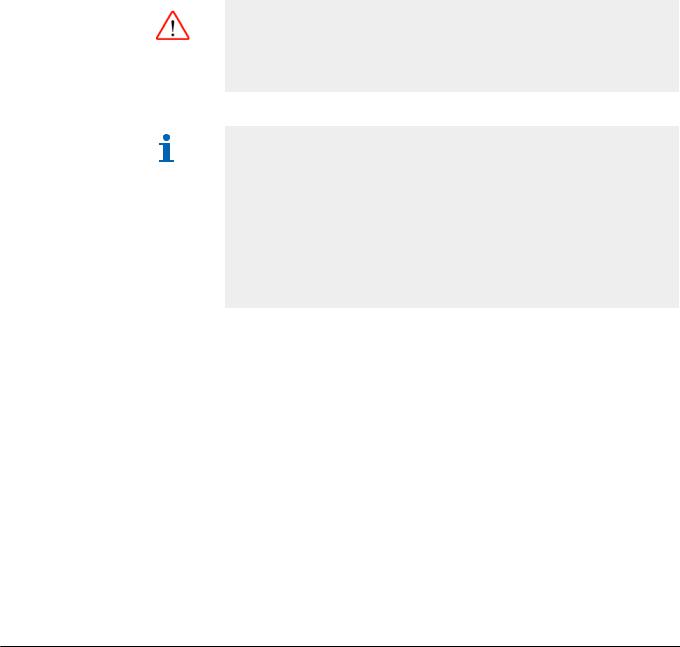
Figure 1 Front view of Fabius GS anesthesia system, for legend see Table 1
5330.500 |
7 |

Function description |
|
Fabius GS |
|
|
|
|
|
|
Table 1 |
Legend to Figure 1 |
|
|
|
|
|
|
No. |
|
Name |
|
|
|
|
|
|
|
|
|
1 |
|
Trolley |
|
|
|
|
|
2 |
|
O2 flush |
|
|
|
|
|
3 |
|
Cosy 2 breathing system |
|
|
|
|
|
4 |
|
Ventilator |
|
|
|
|
|
5 |
|
Oxygen flowmeter (auxiliary) |
|
|
|
|
|
6 |
|
Display |
|
|
|
|
|
7 |
|
Control panel |
|
|
|
|
|
8 |
|
Vaporizers |
|
|
|
|
|
9 |
|
Cylinder Pressure Gauges |
|
|
|
|
|
10 |
|
Pipeline Pressure Gauges |
|
|
|
|
|
11 |
|
Flow Control Valves |
|
|
|
|
|
12 |
|
Total fresh gas flowmeter |
|
|
|
|
| <![if ! IE]> <![endif]>reserved. Copyright reserved. |
<![if ! IE]> <![endif]>Released Printed on 10.11.05 F5330500 Function Description.fm |
| <![if ! IE]> <![endif]>All rights |
<![if ! IE]> <![endif]>Version 1.0 |
8 |
5330.500 |

Fabius GS |
Function description |
|
|
| <![if ! IE]> <![endif]>Function Description.fm |
|
| <![if ! IE]> <![endif]>Released Printed on 10.11.05 F5330500_ |
<![if ! IE]> <![endif]>reserved. Copyright reserved. |
| <![if ! IE]> <![endif]>Version 1.0_ |
<![if ! IE]> <![endif]>All rights |
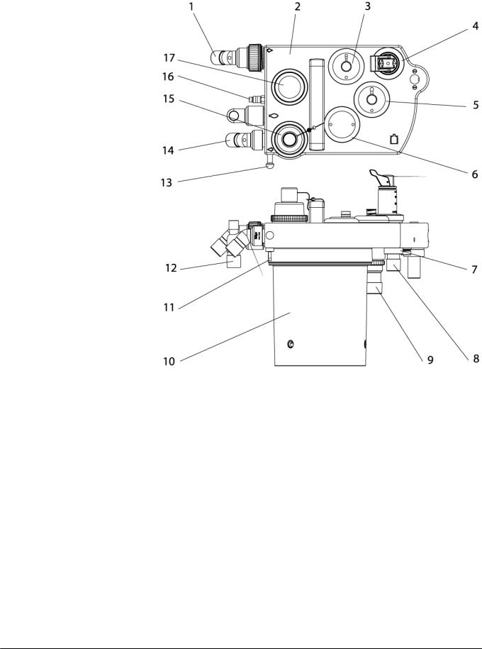
Figure 2 Rear view showing interface panel and power entry, for legend
|
|
see Table 2 |
Table 2 |
Legend to Figure 2 |
|
|
|
|
|
No. |
Name |
|
|
|
|
|
|
1 |
Serial communication ports (only one is shown) |
|
|
|
|
2 |
Tube connection for PEEP valve |
|
|
|
|
3 |
Tube connection for APL bypass valve |
|
|
|
|
4 |
O2 sensor connection |
|
|
|
|
5 |
Airway pressure connection |
|
|
|
|
6 |
Spirolog sensor connection |
|
|
|
|
7 |
Power entry |
|
8Cover for power fuses (2x 2.5 A)
5330.500 |
9 |
Function description |
Fabius GS |
|
|
No. Name
9ON/OFF switch
10 |
Battery fuse |
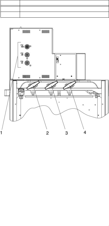
Figure 3 Rear view showing gas pipeline and PIN index cylinder connections, for legend see Table 3
|
No. |
|
Name |
<![if ! IE]> <![endif]>_Description.fm |
||
Table 3 |
Legend to Figure 3 |
|
||||
|
|
|
|
|
|
<![if ! IE]> <![endif]>Function |
|
|
|
|
|
|
|
|
1 |
|
Pipeline tube connections |
|
|
|
|
|
|
|
|||
|
|
|
|
|
<![if ! IE]> <![endif]>F533050010.11.05onPrintedReleased _ |
|
|
2 |
|
N2O or AIR PIN index cylinder connections |
|
<![if ! IE]> <![endif]>reserved.Copyrightreserved. |
|
|
|
|
|
|
||
|
3 |
|
O2 PIN index cylinder connection |
|
||
|
|
|
|
|||
|
|
|
|
|
|
|
|
4 |
|
O2 PIN index cylinder connection |
|
|
|
|
|
|
|
|
<![if ! IE]> <![endif]>All rights |
<![if ! IE]> <![endif]>Version 1.0 |
|
|
|
|
|
||
|
|
|
|
|
|
|
10 |
|
5330.500 |
|
|
|
|
Fabius GS |
Function description |
|
|
| <![if ! IE]> <![endif]>Function Description.fm |
|
| <![if ! IE]> <![endif]>Released Printed on 10.11.05 F5330500_ |
<![if ! IE]> <![endif]>reserved. Copyright reserved. |
| <![if ! IE]> <![endif]>Version 1.0_ |
<![if ! IE]> <![endif]>All rights |
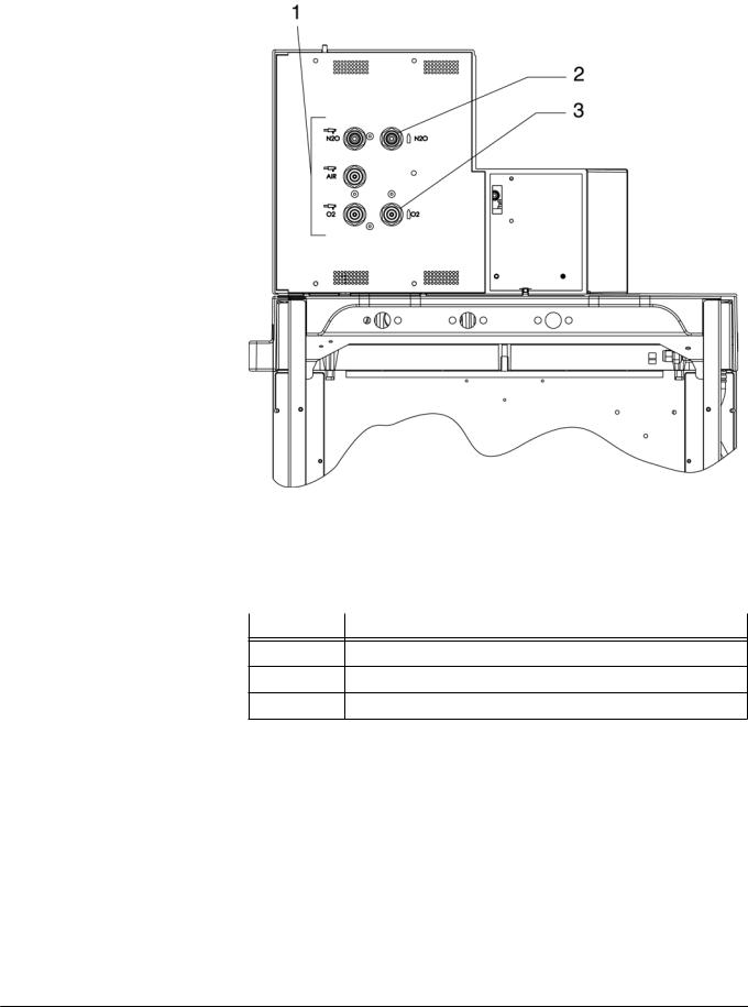
Figure 4 Rear view showing gas pipeline and cylinder connections (units
|
without PIN index cylinder connections), for legend see Table 4 |
Table 4 |
Legend to Figure 4 |
|
|
No. |
Name |
1Pipeline tube connections
2N2O cylinder connection
3O2 cylinder connection
5330.500 |
11 |
Function description |
Fabius GS |
|
|
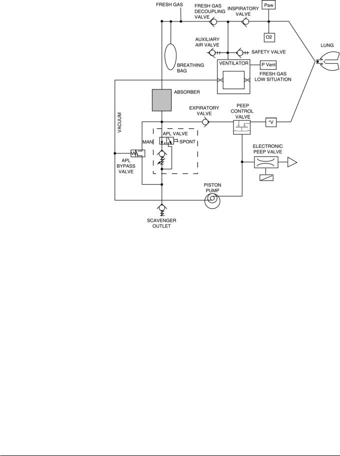
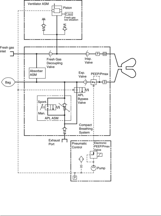
2Function diagram of Fabius GS
Figure 5 Function diagram of Fabius GS - Cosy 2 breathing system
| <![if ! IE]> <![endif]>reserved. Copyright reserved. |
<![if ! IE]> <![endif]>Released Printed on 10.11.05 F5330500 Function Description.fm |
| <![if ! IE]> <![endif]>All rights |
<![if ! IE]> <![endif]>Version 1.0 |
12 |
5330.500 |
Fabius GS |
Function description |
|
|
| <![if ! IE]> <![endif]>Function Description.fm |
|
| <![if ! IE]> <![endif]>Released Printed on 10.11.05 F5330500_ |
<![if ! IE]> <![endif]>reserved. Copyright reserved. |
| <![if ! IE]> <![endif]>Version 1.0_ |
<![if ! IE]> <![endif]>All rights |
Figure 6 Function diagram of Fabius GS - Cosy 2.5 (2.6) breathing system
5330.500 |
13 |
Function description |
Fabius GS |
|
|
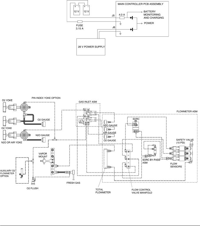
3Battery backup
Fabius GS backup power is provided by two series-connected 12 V rechargeable batteries. These batteries remain on charge as long as the machine is plugged into an active AC outlet. Should power supply fail while the machine is in operation, the batteries will allow the machine to continue operating for a minimum of 45 minutes, provided that the batteries are fully charged.
The batteries are accessible by opening the ventilator compartment. The 3.15A battery fuse is located at the back of the control box.
Figure 7 Battery backup arrangement
4Fabius GS piping diagram
Figure 8 Fabius GS piping diagram
14
| <![if ! IE]> <![endif]>reserved. Copyright reserved. |
<![if ! IE]> <![endif]>Released Printed on 10.11.05 F5330500 Function Description.fm |
| <![if ! IE]> <![endif]>All rights |
<![if ! IE]> <![endif]>Version 1.0 |
5330.500
Fabius GS |
Function description |
|
|
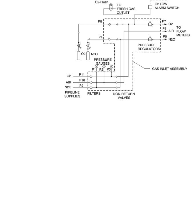
5Function descrip- The supply gases flow through the filters and non-return valves in the gas
tion of gas box
inlet assembly. Pipeline supply pressures are indicated on pipeline pressure gauges located on the flowmeter assembly. Cylinder pressure gauges are located on the trolley assembly. The pressures of O2 and N2O delivered to the flowmeter assembly are set by regulators on the gas inlet assembly.
Should the O2 supply fail or if its pressure decrease below a certain limit, the O2 low alarm switch signals an alarm.
Figure 9 Gas box function diagram, part 1
If the O2 flush button is pressed, oxygen is delivered to the fresh-gas outlet. The fresh-gas ejector prevents the fresh gas from flowing back into the anesthetic vaporizer. This avoids an increase in the anesthetic gas concentration.
| <![if ! IE]> <![endif]>Function Description.fm |
|
| <![if ! IE]> <![endif]>Released Printed on 10.11.05 F5330500_ |
<![if ! IE]> <![endif]>reserved. Copyright reserved. |
| <![if ! IE]> <![endif]>Version 1.0_ |
<![if ! IE]> <![endif]>All rights |
5330.500 |
15 |

Function description |
Fabius GS |
|
|
6SORC (Sensitive Oxygen Ratio Controller)
Figure 10 Gas box function diagram, part 2
The SORC is a control element that functions like an N2O shut-off device and ensures a vital O2 concentration in the fresh gas. In the event of an O2 shortage, the SORC limits the N2O flow such that the O2 concentration in the fresh gas does not decrease below 21 vol.%.
If the O2 flow control valve is closed or if the O2 flow is lower than or equal to 200 mL/min, the SORC interrupts the N2O flow.
N2O can be added as of an O2 flow of approx. 300 mL/min. In this case, the SORC also prevents O2 concentrations below 21 vol.%.
The SORC bypass allows O2 to bypass the restrictor in the SORC when O2 flows above 10 L/min are needed.
| <![if ! IE]> <![endif]>reserved. Copyright reserved. |
<![if ! IE]> <![endif]>Released Printed on 10.11.05 F5330500 Function Description.fm |
| <![if ! IE]> <![endif]>All rights |
<![if ! IE]> <![endif]>Version 1.0 |
16 |
5330.500 |
Fabius GS |
Function description |
|
|
| <![if ! IE]> <![endif]>Function Description.fm |
|
| <![if ! IE]> <![endif]>Released Printed on 10.11.05 F5330500_ |
<![if ! IE]> <![endif]>reserved. Copyright reserved. |
| <![if ! IE]> <![endif]>Version 1.0_ |
<![if ! IE]> <![endif]>All rights |
Figure 11 SORC function diagram, part 1
The O2 and N2O flows are adjusted with the flow control valves.
Restrictors located at the outlets of the SORC generate back-pressures. These back-pressures exert a force on the control diaphragms of the SORC. The O2 back-pressure opens the SORC. The N2O back-pressure closes the SORC. The pressure ratio at the control diaphragm affects the N2O flow.
The resistors and the spring force are dimensioned such that a minimum concentration of 21 vol.% of O2 is always ensured. The maximum O2 flow is approx. 12 L/min.
Figure 12 SORC function diagram, part 2, for legend see Table 5
5330.500 |
17 |

Function description |
Fabius GS |
|
|
|
|
|
Table 5 |
Legend to Figure 12 |
|
|
|
|
No. |
Name |
|
|
|
|
|
|
|
1 |
Control diaphragms |
|
|
|
|
2 |
Restrictors |
|
|
|
|
3 |
N2O non-return valve |
|
|
|
|
4 |
Operating-point adjusting screw |
|
|
|
|
5 |
Flow control valves |
|
|
|
7Cosy 2 breathing The Cosy 2 breathing system allows three modes of patient ventilation:
system |
– Manual ventilation and spontaneous breathing |
|
|
||
|
– |
Volume controlled ventilation |
|
– |
Pressure controlled ventilation |
The APL valve (adjustable pressure limiting valve), lever type, has a selector switch which can be used to toggle between “MAN” and “SPONT”.
On APL valves with control knob, switching from “IPPV/SPONT” to “MAN” is carried out by turning the knob.
In the “MAN” position, the breathing system is closed to atmosphere. This position is used for manual ventilation of the patient. The APL valve opening pressure can be adjusted from 5 to 70 cmH2O (mbar).
In the “SPONT” position the APL valve is open to atmosphere. This position is used for spontaneous breathing.
Using the control box and the PEEP Pmax valve, the pressure limit (Pmax) can also be adjusted during volume control from 15 cmH2O (mbar) to
70 cmH2O (mbar) via the membrane keypad.
| <![if ! IE]> <![endif]>reserved. Copyright reserved. |
<![if ! IE]> <![endif]>Released Printed on 10.11.05 F5330500 Function Description.fm |
| <![if ! IE]> <![endif]>All rights |
<![if ! IE]> <![endif]>Version 1.0 |
18 |
5330.500 |
Fabius GS |
Function description |
|
|
| <![if ! IE]> <![endif]>Function Description.fm |
|
| <![if ! IE]> <![endif]>Released Printed on 10.11.05 F5330500_ |
<![if ! IE]> <![endif]>reserved. Copyright reserved. |
| <![if ! IE]> <![endif]>Version 1.0_ |
<![if ! IE]> <![endif]>All rights |
Figure 13 Cosy 2 breathing system, for legend see Table 6
Table 6 |
Legend to Figure 13 |
|
|
No. |
Name |
|
|
|
|
1 |
Expiratory connection |
|
|
2 |
Flow sensor (Spirolog) (not shown) |
|
|
3 |
PEEP/Pmax valve |
|
|
4 |
MAN/SPONT APL valve |
|
|
5 |
APL Bypass valve |
|
|
6 |
Fresh-gas decoupling valve |
|
|
7 |
Fresh-gas port |
|
|
8 |
Ventilator port |
|
|
9 |
Anesthetic gas scavenging port |
|
|
10 |
Absorber |
|
|
5330.500 |
19 |
 Loading...