


Field
Service
Instruction
Part Number: 4116708
Rev: -
Date: 17 August 2000
Installation Instructions:
Incubator 8000 Control Unit

Dräger Medical, Inc.
Recall Incubator 8000 series in the USA and Canada
Installation Instructions for Control Unit and Feedback Form
Dear Customer,
You have received a modified Control Unit with some additional parts for your Incubator 8000 series. Please read all Instructions before you start the installation and use the feedback form on page 3 to inform us about the device you have upgraded. As a medical device manufacturer we are required to report the results of the corrective action to the FDA and Health Canada, therefore a feedback form must be completed for each Incubator modified. If you have any questions, please feel free to call Dräger Medical, Inc. at 1 800 4 DRAGER and ask for Service.
Sincerely,
Andreas Lenke
Technical Service Manager
DrägerService
1 |
Action to be taken: |
|
• |
Installation of modified Control Unit. |
|
• |
Retrofitting 2 warning labels according to TSB Incubator 8000 IC/SC/NC # 19. |
|
2 |
Parts needed for conversion: |
|
•Modified Control Unit
•2 pieces label P/N 2M22351
•Conversion Instructions (see list of documents in section 3)
Recall Incubator 8000 |
Installation Instructions for Control |
August 18, 2000 |
1/3 |
|
Unit and Feedback Form |
|
|

Dräger Medical, Inc.
3 Attached documents for conversion:
-Skin-Temperature Measurement Conversion Instructions (Incubator 8000 IC/SC/NC)
-TSB Incubator 8000 IC/SC/NC # 19
-Adhesive statement 2M22363 (according to TSB Incubator 8000 IC/SC/NC # 19)
-Incubator 8000 IC/SC/NC, Electrical Safety Test in the USA and Canada according to CAN/CSA - 22.2 No. 601.1 - M90
4 Installation Instructions for Units in the USA and Canada
4.1Please fill out the feedback form during the installation. Some of the data is on the parts that will be installed.
4.2Observe ESD precautions
Electrostatic discharge may damage electrostatic sensitive devices. When handling electrostatic sensitive devices, use always a staticdissipative mat and a static-dissipative wrist wrap.
4.3For the installation of the Control Unit use the attached instructions "SkinTemperature Measurement Conversion Instructions (Incubator 8000 IC/SC/NC)" and begin with step 31.
Note: Install the upgraded Control Unit in the original Incubator only.
4.4For testing electrical safety use the attached instructions "Incubator
8000 IC/SC/NC, Electrical Safety Test in the USA and Canada according to CAN/CSA - 22.2 No. 601.1 - M90".
4.5Retrofit 2 warning labels according to the attached instructions "Adhesive statement 2M22363".
4.6Fill out feedback form and send it back by fax.
Recall Incubator 8000 |
Installation Instructions for Control |
August 18, 2000 |
2/3 |
|
Unit and Feedback Form |
|
|

Dräger Medical, Inc.
Feedback Form Incubator 8000 series / Installation Control Unit
DrägerService
Andreas Lenke
3122 Commerce Drive
Telford, PA 18969
1-215-721-5789
Hospital name and address:
Name: ___________________________________________________
Department: ___________________________________________________
Street: ___________________________________________________
City: |
___________________ |
State: _____ Zip: _________ |
Tel.: ___________________________________________________
Fax.: ___________________________________________________
Name of device: |
|
Part No. Inc. (number on |
|
Serial No. Incu. (number on |
||||
Incubator 8000 IC |
|
rating plate under "Typ"): |
|
rating plate under "Fabr. Nr."): |
||||
Incubator 8000 SC |
|
|
|
|
|
A R __ __ - __ __ __ __ |
||
Incubator 8000 NC |
|
|
|
|
|
|||
This is to confirm the following conversion of the Incubator: |
||||||||
The following updated Control Unit has been installed: |
||||||||
|
P/N: |
|
|
|
S/N: |
A R __ __ - __ __ __ __ |
||
2 warning labels according to TSB # 19 are placed on the device |
||||||||
Your Name (please print): |
Title: |
Date: |
|
|
Signature: |
|||
|
|
|
|
|
|
|
|
|
Recall Incubator 8000 |
Installation Instructions for Control |
August 18, 2000 |
3/3 |
|
Unit and Feedback Form |
|
|
Dräger Medizintechnik |
|
|
|
1Skin-Temperature Measurement Conversion Instructions (Incubator 8000 IC/SC/NC)
Please note: For removal of control unit see step 1 - 10, for installation see step 31 - 47.
1.1General Information
•Perform the "skin-temperature measurement" conversion only if the
Incubator 8000 IC/SC/NC is equipped with a skin-temperature module, see the following Figure.
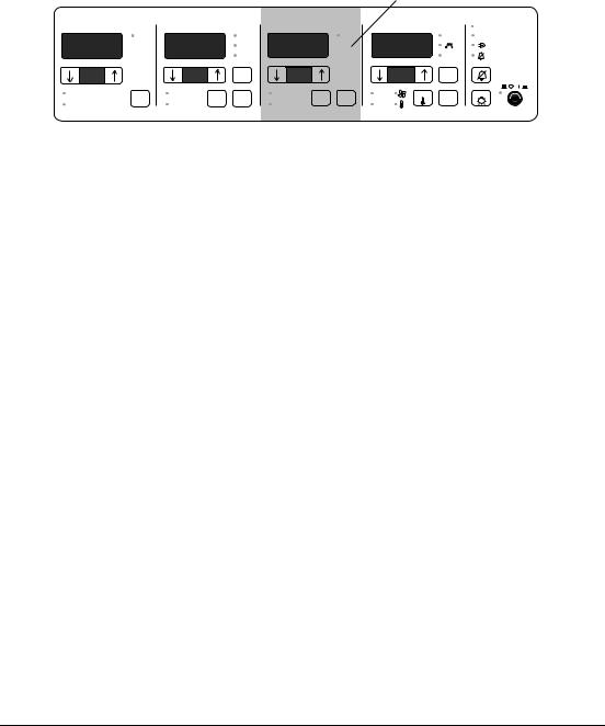
1.1.1Incubator 8000 IC/SC/NC with skin-temperature control
|
|
Skin-temperature module |
Function: Skin-temperature control |
||||
% FEUCHTE/HUMID. |
VOL.%O 2 |
|
C HAUT/SKIN/PEAU/PIEL |
° C LUFT/AIR |
|
Alarm |
|
|
Control |
|
Control |
Control |
|
Control |
Inop. |
|
Vol.% |
|
Cal. |
|
|
|
|
% |
O2 |
|
° C |
|
° C |
>37 ˚C |
|
|
|
|
>40% |
|
|
|
|
% |
Vol.%O 2 |
|
>40% |
° C |
° C |
>37 ° C |
|
|
|
|
|
|
|
||
H2O |
± 5 Vol.% |
Cal. |
± 0,5 ° C |
Check |
± 1,5 ° C |
Reset |
Check |
|
Control |
Control |
36 ° C Control |
|
Control |
|
|
|
21% |
|
|
||||
Sensor |
Sensor |
Sensor |
±0,1 |
Sensor |
|
|
|
|
|
|
|||||
Fig. 1: Front view of the Incubator's control unit with skin-temperature control
U-Inkubator8000IC-SC-NC.fm 17.08.00 |
For internal use only. Copyright reserved. |
6141.2XX Incubator 8000IC/SC/NC |
08/2000 |
Conversion Instructions |
Page 1 of 20 |

Dräger Medizintechnik |
|
|
|
The Incubator 8000 IC/SC/NC is equipped with different Analog PCBs:
8200920-00
8200920-01
8200922-13
8200922-16 or
8290678-01
8290678-02
8290678-03
8290680-04
Analog PCB, part numbers 8200920-00 8200920-01 8200922-13 8200922-16
can be identified by the following characteristics:
The skin-temperature sensor socket is either fitted on the environmental sensor or on the rear panel of the Incubator.
Analog PCB, part numbers 8290678-01 8290678-02 8290678-03 8290680-04
can be identified by the following characteristics:
A yellow skin-temperature sensor socket is fitted on the left side of the Incubator.
U-Inkubator8000IC-SC-NC.fm 17.08.00 |
For internal use only. Copyright reserved. |
6141.2XX Incubator 8000IC/SC/NC |
08/2000 |
Conversion Instructions |
Page 2 of 20 |

U-Inkubator8000IC-SC-NC.fm 17.08.00 |
For internal use only. Copyright reserved. |
Dräger Medizintechnik |
|
|
|
Parts included in the conversion kit
•Conversion kit for Incubator 8000 IC/SC/NC with a yellow skin-temperature sensor socket on the left side of the Incubator:
|
|
Part Number |
|
|
|
Conversion Instructions |
|
|
|
|
|
Adhesive label |
|
2M22384 |
|
|
|
EPROM |
Software version 11.02 |
2M22332 |
|
(Incubator 8000 NC/SC) |
|
|
|
|
EPROM |
Software version 21.02 |
2M22331 |
|
(Incubator 8000 IC) |
|
|
|
|
Analog PCB |
|
2M22404-00 |
|
|
|
or |
|
|
|
|
|
Analog PCB |
|
2M22405-00 |
|
|
|
or |
|
|
|
|
|
Analog PCB |
|
2M22406-00 |
|
|
|
or |
|
|
|
|
|
Analog PCB |
|
2M22407-00 |
|
|
|
•Conversion kit for Incubator 8000 IC/SC/NC with the skin-temperature sensor socket fitted either on the environmental sensor or on the rear panel of the Incubator:
|
|
Part Number |
|
|
|
Conversion Instructions |
|
|
|
|
|
Adhesive label |
|
2M22384 |
|
|
|
EPROM |
Software version 10.05 |
2M22326 |
|
(Incubator 8000 NC/SC) |
|
|
|
|
EPROM |
Software version 20.04 |
2M22327 |
|
(Incubator 8000 IC) |
|
|
|
|
Analog PCB |
|
2M22400-00 |
|
|
|
or |
|
|
|
|
|
Analog PCB |
|
2M22401-00 |
|
|
|
or |
|
|
|
|
|
Analog PCB |
|
2M22402-00 |
|
|
|
or |
|
|
|
|
|
Analog PCB |
|
2M22403-00 |
|
|
|
6141.2XX Incubator 8000IC/SC/NC |
08/2000 |
Conversion Instructions |
Page 3 of 20 |
U-Inkubator8000IC-SC-NC.fm 17.08.00 |
For internal use only. Copyright reserved. |
Dräger Medizintechnik |
|
|
|
• If all items are included, proceed to conversion procedure, step 1.
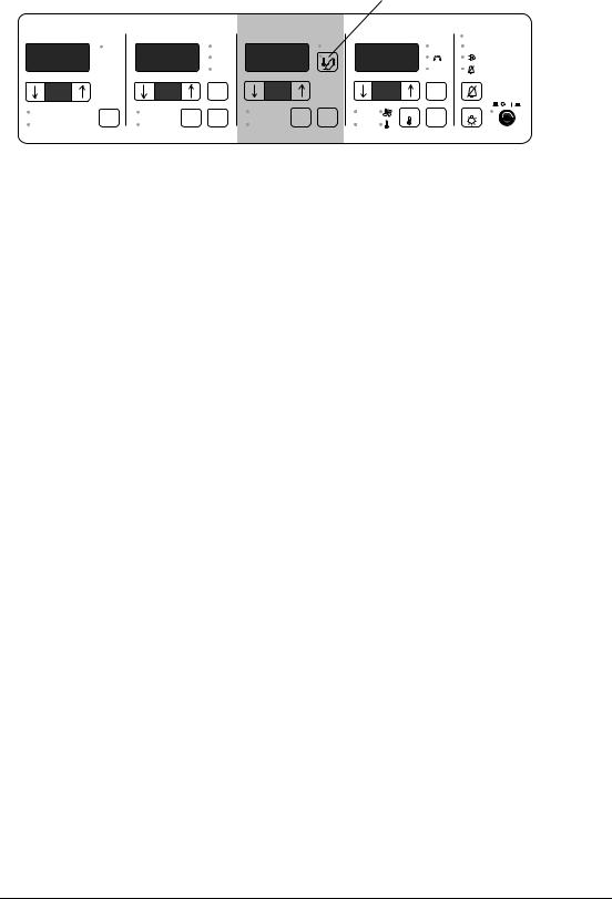
1.1.2Incubator 8000 IC/SC/NC with thermomonitoring
|
|
|
Skin-temperature module |
Function: Thermomonitoring |
||||
|
|
|
|
|
||||
% FEUCHTE/HUMID. |
VOL.%O 2 |
|
|
C HAUT/SKIN/PEAU/PIEL |
° C LUFT/AIR |
|
Alarm |
|
Control |
|
|
Control |
|
Control |
|
Control |
Inop. |
|
Vol.% |
|
Cal. |
° C |
|
° C |
|
|
% |
O2 |
|
>40% |
|
>37 ˚ C |
|
||
|
|
|
|
|
|
|
||
% |
Vol.%O 2 |
|
>40% |
|
° C |
° C |
>37 ° C |
|
|
|
|
|
|
|
|
||
H2O |
± 5 Vol.% |
Cal. |
|
± 0,5 ° C |
Check |
± 1,5 ° C |
Reset |
Check |
Control |
|
Control |
|
36 ° C Control |
|
Control |
|
|
|
21% |
|
|
|
||||
Sensor |
Sensor |
|
Sensor |
±0,1 |
Sensor |
|
|
|
|
|
|
|
|||||
Fig. 2: Front view of the Incubator's control unit with thermomonitoring
Parts included in the conversion kit
•Before starting the conversion, check that all items listed below are included in the conversion kit:
|
|
Part Number |
|
|
|
Conversion Instructions |
|
|
|
|
|
Adhesive label |
|
2M22384 |
|
|
|
EPROM |
Software version 11.02 |
2M22332 |
|
(Incubator 8000 NC/SC) |
|
|
|
|
EPROM |
Software version 21.02 |
2M22331 |
|
(Incubator 8000 IC) |
|
|
|
|
Analog PCB |
|
2M22404-00 |
|
|
|
or |
|
|
|
|
|
Analog PCB |
|
2M22405-00 |
|
|
|
or |
|
|
|
|
|
Analog PCB |
|
2M22406-00 |
|
|
|
or |
|
|
|
|
|
Analog PCB |
|
2M22407-00 |
|
|
|
• If all items are included, proceed to conversion procedure, step 1.
6141.2XX Incubator 8000IC/SC/NC |
08/2000 |
Conversion Instructions |
Page 4 of 20 |

Dräger Medizintechnik |
|
|
|
1.2Conversion Procedure
1.Move electrical height adjustment (optional) of the Incubator 8000 IC/SC/NC to the highest position.
2.Switch off the Incubator 8000 IC/SC/NC using the ON/OFF switch.
3.Unplug the power plug of the Incubator 8000 IC/SC/NC from the mains socket-outlet.
Electrostatic discharge may damage electrostatic sensitive devices. When handling electrostatic sensitive devices, use a static-dissipative mat and a static dissipative wrist strap.
4.Observe ESD precautions.
5.Support the Incubator's cover plate with one hand and turn catches (a) 90° counterclockwise.
a
Fig. 3: Left and right side view of the Incubator 8000 IC/SC/NC
U-Inkubator8000IC-SC-NC.fm 17.08.00 |
For internal use only. Copyright reserved. |
6141.2XX Incubator 8000IC/SC/NC |
08/2000 |
Conversion Instructions |
Page 5 of 20 |

U-Inkubator8000IC-SC-NC.fm 17.08.00 |
For internal use only. Copyright reserved. |
Dräger Medizintechnik |
|
|
|
6.Unlock latches (b) of the electronic module and fold down the electronic unit.
D Inkubator 8000 |
b |
b |
Fig. 4: View of the Incubator 8000 IC/SC/NC
Risk of damage to equipment. The electronic unit is connected with the Incubator's cables which might be damaged during disassembly. To avoid damage to these cables, carefully remove the electronic unit as shown in the following step.
7.Remove the following cable connectors from the electronic unit:
- Disconnect cable connectors of the protective conductors (c) from the housing frame
of the electronic unit.
- Take the cable connector (d) by the connector and disconnect it from the Analog PCB. - Take the cable connector (e), if present, by the connector and disconnect it from the Analog PCB.
c 
 d
d
e 
Fig. 5: Cable connections of the electronic unit
6141.2XX Incubator 8000IC/SC/NC |
08/2000 |
Conversion Instructions |
Page 6 of 20 |
 Loading...