


 Loading...
8.Repair Information Unit, Electronics Module, Climatic Sensor
Table of Contents |
|
|
8.1 Unit |
................................................................................................................................ |
2 |
8.1.0 ................................................................................................... |
Table of Contents |
2 |
8.1.1 ....................Information on Unit 2M 20 276 / 2M 20 615 (of Inc. 8000 SC/IC/NC) |
3 |
|
8.1.2 ...............................................................................................PCB Unit and Fuses |
3 |
|
8.1.3 ..........................................................................Air Heating with Thermal Release |
6 |
|
8.1.4 ...............................................Boiler with Water heating and Thermostatic Switch |
6 |
|
8.1.5 ............................................................................................................... |
Fan Motor |
8 |
8.1.6 ............................................................................................... |
Mains Transformer |
10 |
8.1.7 ........................................................................................... |
Semiconductor Relay |
10 |
8.1.8 ...........................................................................Test of Heating Unit (Complete) |
11 |
|
8.1.9 ................................................................................................. |
Voltage Selection |
26 |
8.1.10 ..........................................................Replacement of Unit in the event of Repair |
27 |
|
8.1.11 ................................................................Repair Information and Change Status |
27 |
|
8.2 Electronics ......................................................................................................module |
28 |
|
8.2.0 ................................................................................................. |
Table of Contents |
28 |
8.2.1 ............................................................................................................ |
Keyboards |
30 |
8.2.2 ..............................................................................PCB Display Air Temperature |
36 |
|
8.2.3 .....................PCB Display (of options), PCB Display Skin (as of SW 11 and 21) |
39 |
|
8.2.4 ....................................................PCB Display Humidity (only Inc. 8000 SC/NC) |
42 |
|
8.2.5 .............................................................................................................. |
PCB CPU |
44 |
8.2.6 .................................................................................PCB Analog with PCB Filter |
56 |
|
8.2.7 .................................................................................................. |
PCB Power Pack |
74 |
8.2.8 ..........................................................................PCB Motherboard and PCB Fan |
80 |
|
8.2.9 ........................................................................................................... |
PCB Switch |
84 |
8.2.10 .......................................................................................................................N/A |
84 |
|
8.2.11 ......................................................................PCB Controller (RS232) 82 90 581 |
85 |
|
8.3 Climatic ............................................................................................................sensor |
90 |
|
8.3.0 ................................................................................................. |
Table of Contents |
90 |
8.3.1 ..........................................................................Information on Climatic Sensors |
90 |
|
8.3.2 ..........................................................Climatic Sensor 82 90 380 and 2M 21 688 |
91 |
|
8.3.3 ........................................................................................ |
Testing and Adjustment |
92 |
8.3.4 ...................................................................................... |
Replacement and Repair |
95 |
8.3.5 ................................................................Repair Information and Change Status |
96 |
|
6141.22x |
Incubator 8000 SC/IC/NC |
Repair Information |
11.99 |
Page 1 of 96 |
8.1Unit
8.1.0Table of Contents
8.1.3
8.1.5
H2O
Air
8.1.4 |
8.1.7 |
8.1.6 |
8.1.2 |
8.1.1Information on Units Used
8.1.2PCB Unit and Fuses
8.1.3Air Heating with Thermal Release
8.1.4Boiler with Water Heating and Thermostatic Switch
8.1.5Fan Motor
8.1.6Mains Transformer
8.1.7Semiconductor Relay
8.1.8Testing of Unit (Complete)
8.1.9Voltage Selection
8.1.10Replacement of Unit in the event of Repair
8.1.11Repair Information and Change Status
6141.22x |
Incubator 8000 SC/IC/NC |
Repair Information |
11.99 |
Page 2 of 96 |
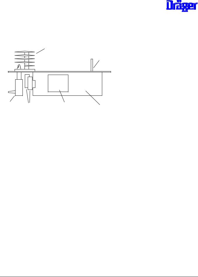
8.1.1Information on Unit 2M 20 276 / 2M 20 615 (of Inc. 8000 SC/IC/NC)
Characteristics:
-PCB Unit 82 90 511
-All connections to printed circuit board plugged-in
-Heating cartridges for one mains voltage only (100 V, 120 V / 127 V or 230 V / 240 V)
-Boiler (complete) plugged-in. In the Inc. 8000 SC/IC/NC it can be removed through a service opening without dismounting the Unit
Since both Units are identical as far as their function is concerned it is possible to use the Unit
2M 20 615 in the Inc. 8000, refer to 8.1.9 "Replacing in the event of Repair".
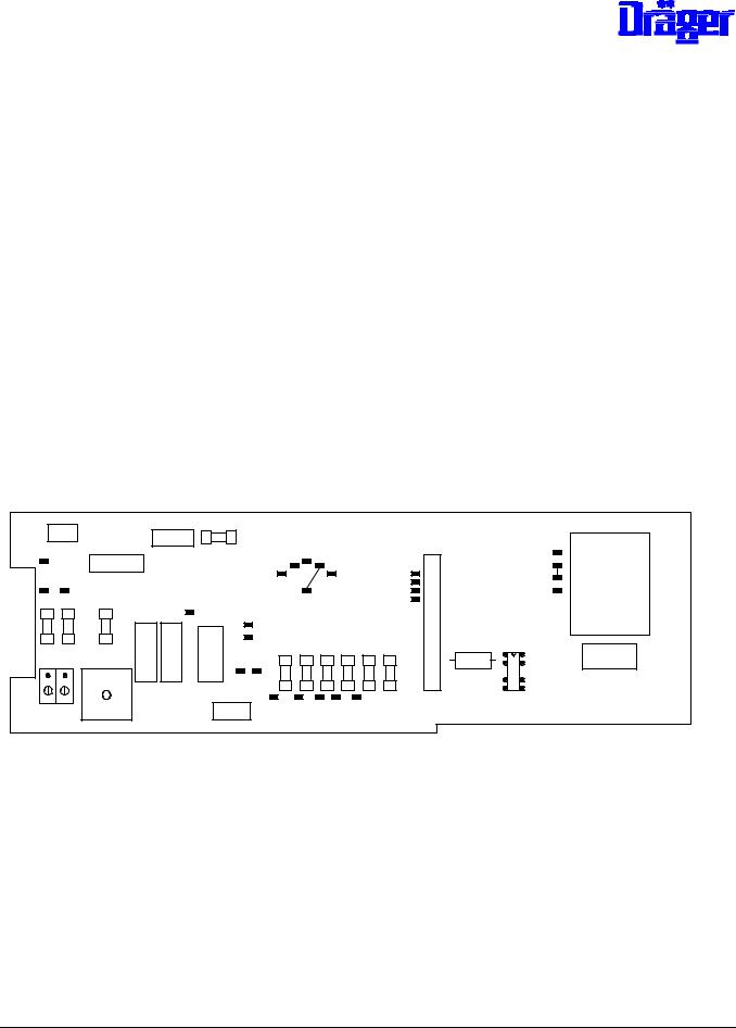
8.1.2PCB Unit and Fuses
Layout Component Mounting Side:
X12 |
|
|
F4 |
|
|
|
|
|
|
|
|
|
|
|
|
|
|
|
X10 |
|
|
|
|
|
|
|
|
|
|
|
|
|
|
||
|
|
|
|
|
|
110 127 230 |
|
|
|
|
|
|
|
||||
T56 |
|
X11 |
|
|
|
|
|
|
|
|
|
T41 |
|
||||
|
|
|
|
|
|
100 |
|
|
240 |
|
|
T3 |
|
T42 |
|
||
T59 |
T61 |
|
|
|
|
|
|
|
|
|
|
|
|
|
T43 |
T54 |
|
|
|
|
|
|
|
|
|
|
|
|
|
T4 |
|
||||
|
|
|
|
|
|
|
|
|
|
|
|
|
T44 |
||||
|
|
|
|
|
|
|
|
|
T60 |
|
|
|
|
T2 |
|
|
|
F1 |
F2 |
|
|
|
|
|
|
|
|
|
|
|
|
|
|
||
F3 |
T58 |
|
|
|
|
|
|
|
|
|
|
T5 |
|
|
|
||
|
|
|
|
|
|
|
|
|
|
|
|
|
X1 |
|
|
|
|
|
|
|
|
|
T57 |
|
|
|
|
|
|
|
|
|
|
||
|
|
K1 |
K5 |
K2 |
T55 |
F5 |
F6 |
F7 |
F8 |
F9 |
F10 |
|
|
K4 |
K3 |
||
|
|
T1 |
T6 |
|
|
|
|
|
|
|
C2 |
+ |
|
||||
|
|
|
|
|
|
|
|
|
|
|
|
|
|||||
|
|
T53 |
|
|
|
|
|
|
|
|
|
|
|
|
|
|
|
X3 X4 |
|
|
|
X2 |
|
T7 |
T10 |
T9 |
T8 |
T63 |
|
|
|
|
|
||
|
|
|
|
|
|
|
|
|
|
|
|
|
|
|
|||
|
|
|
|
|
|
|
|
|
|
|
|
|
|
|
|
||
6141.22x |
Incubator 8000 SC/IC/NC |
Repair Information |
11.99 |
Page 3 of 96 |
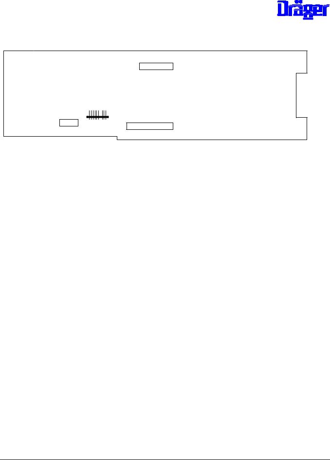
Layout Rear:
X7
X5
X13
X6
Component Mounting without Fuses:
Position |
Component |
Function |
X1 |
Connector 18 13 641 |
Cable connection to electronics module |
X2 |
Connector 18 13 544 |
Cable connection to valve(s) |
X3, X4 |
Terminal 68 04 759 |
Mains connection |
X5 |
Connector 18 10 669 |
Connection for coil of fan watchdog, |
|
|
Thermostatic switch water shortage and |
|
|
control of semiconductor relay |
X6 |
Connector 18 28 592 |
Connection mains voltage for transformer |
X7 |
Connector 18 28 576 |
Return transformer voltages |
X10 |
Connector 18 28 533 |
Connection heating cartridge for water |
|
|
heating |
X11 |
Connector 18 28 541 |
Connection semiconductor relay supply side |
X12 |
Connector 18 28 525 |
Connection heating cartridge of air heating |
X13 |
Connector 18 28 533 |
Connection fan motor |
K1, K5 |
Relay 18 30 732 |
Mains closing relay |
K2 |
Relay 18 21 474 |
Safety relay for heating |
K3 |
Relay 18 21 474 |
Safety relay for valve(s) |
K4 |
Relay 83 01 198 |
Safety relay for disconnection Semiconductor |
|
|
relay of heating valve(s) |
T54 |
Transformer 18 13 927 |
Auxiliary transformer for mains closing relays |
|
|
K1 and K5 |
6141.22x |
Incubator 8000 SC/IC/NC |
Repair Information |
11.99 |
Page 4 of 96 |

Fuses:
Position |
100 V to 127 V |
220 V to 240 V |
||
F1, F2 |
T 6,3 A |
18 15 172 |
T 3,15 A |
18 15 148 |
F 3 |
T 80 mA |
18 14 974 |
T 40 mA |
18 14 931 |
F4 |
T 1A |
18 15 083 |
T 500 mA |
18 15 059 |
F5 |
T 200 mA |
18 15 016 |
T 200 mA |
18 15 016 |
F6 |
T 500 mA |
18 15 059 |
T 500 mA |
18 15 059 |
F7 |
T 2,5 A |
18 15 121 |
T 2,5 A |
18 15 121 |
F8 |
T 1,6 A |
18 15 105 |
T 1,6 A |
18 15 105 |
F9, F10 |
T 160 mA |
18 15 008 |
T 160 mA |
18 15 008 |
Testing:
Refer to 8.1.8 "Testing Unit (complete)"
Replacement in the event of repair:
In the event of repair the PCB Unit 82 90 511 (complete) can be replaced or components can be renewed. All relays are available for this purpose, refer to component mounting list.
6141.22x |
Incubator 8000 SC/IC/NC |
Repair Information |
11.99 |
Page 5 of 96 |
8.1.3Air Heating with Thermal Release
Three different heating cartridges are uses in this Unit:
- |
220 |
V to 240 V (132 Ohm) |
2M 20 329 |
- |
120 |
V / 127 V (33 Ohm) |
2M 20 331 |
- |
100 |
V (25 Ohm) |
2M 20 669 |
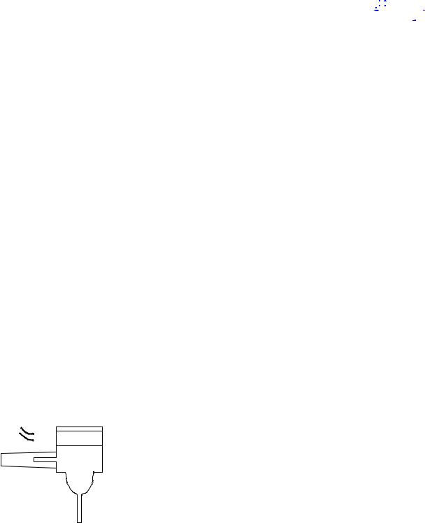
Prolonged heating cartridges are in use since 1992. When installing these heating cartridges lock them using an M4-screw.
M4
8.1.3.3Thermostatic Switch
A safety thermostat which has been tripped must be replaced, no soldering permitted. Prior to replacement, determine cause for tripping, for example:
-wrong heating cartridges
-device assembled incorrectly
The resistance of the thermostat can be checked at its contacts.
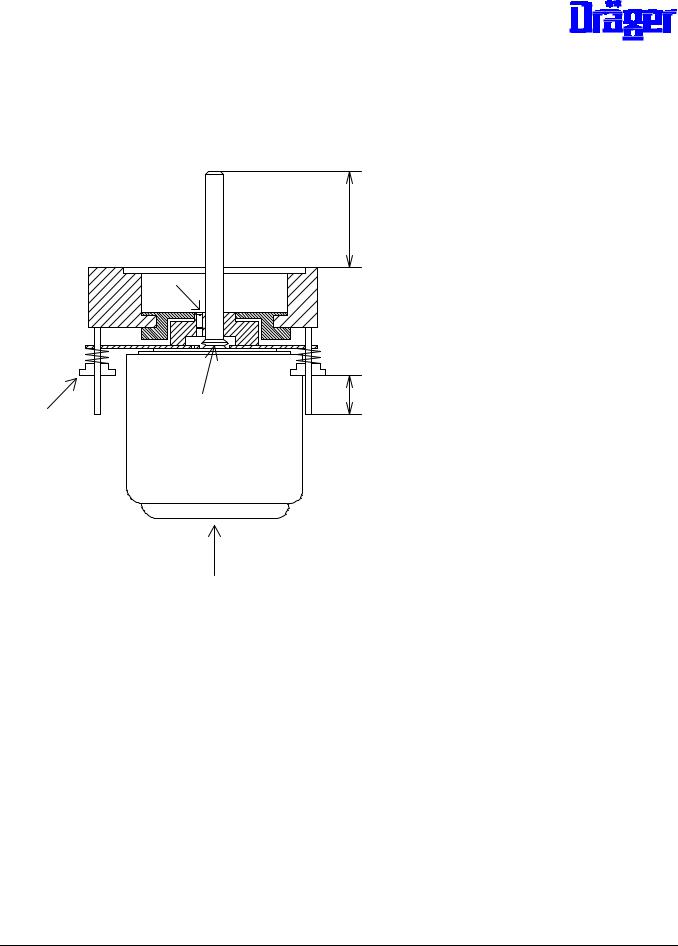
8.1.4Boiler with Water heating and Thermostatic Switch
The boiler system is a plug-in unit consisting of:
-Aluminum housing 2M 20 291
-Heating cartridge for 230 V, 120 V / 127 V or 100 V
- |
Cap for vaporizer 2M 20 292 |
- |
O-ring cap 2M 08 777 |
6141.22x |
Incubator 8000 SC/IC/NC |
Repair Information |
11.99 |
Page 6 of 96 |
|
|
|
|
|
|
|
|
|
|
|
|
|
|
|
|
|
|
|
|
|
|
|
|
|
|
|
|
|
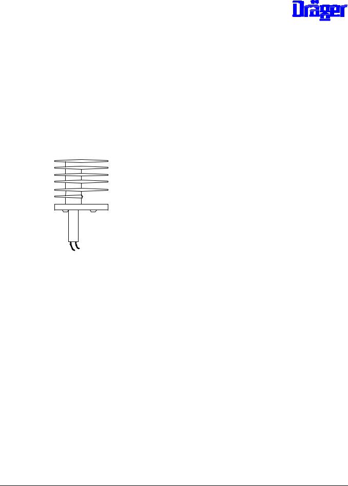
- |
Thermostatic switch water shortage alarm 115 °C 2M 20 381 |
|
|
|
|
|
|
|
|
|
|
|
|
|
|
|
|
|
|
|||||||||
-Safety thermostat 140 °C 2M 20 382
-Plug-in connector
All components can be replaced in the event of repair. If the safety thermostat has been tripped both thermostatic switches must be replaced.
Service:
The condition of the boiler housing must be checked every six months. If the vaporizer chamber is soiled it can be scraped out.
Heating cartridges:
-220 V to 240 V (530 Ohm)2M 20 327
-120 V / 127 V (132 Ohm) 2M 20 328
- |
100 V (100 Ohm) 2M 20 668 |
Prolonged heating cartridges are in use since 1992. As before, the end of the heating cartridge must be flush with the boiler housing.
|
|
|
|
|
|
|
|
|
|
|
|
|
|
6141.22x |
Incubator 8000 SC/IC/NC |
Repair Information |
11.99 |
Page 7 of 96 |
||
8.1.5Fan Motor
Fan motor (simplified representation):
43,5 +/- 0,5
A
D |
C |
|
E |
||
|
B
Service required:
The fan motor must be lubricated every six months with oil 2M 07 839. Procedure: Remove screw A located next to the motor shaft and apply approx. 10 drops of oil into the bore hole.
Bearing play:
The bearing play can be adjusted using screw B. The screw must be adjusted such to allow a motor shaft play of approx. 0.2 mm. The screw must be sealed with locking compound.
6141.22x |
Incubator 8000 SC/IC/NC |
Repair Information |
11.99 |
Page 8 of 96 |

Replacing the Fan Motor
Procedure:
-Interrupt mains connection to Incubator and remove Unit
-Unscrew coil of the fan watchdog from aluminum block of the motor mount
-Disconnect cable connection from motor to printed circuit board
-Unscrew fixing bracket underneath the motor
-Measure and write down dimension E of the 4 retaining screws D
-Remove 4 retaining screws D
-Using oil 2M 07 839 lubricate later bearing surface of V-ring C of the new motor
-Plug new motor with springs onto threaded pins and screw 4 retaining screw D onto dimension E
-Precision adjustment:
While the Unit is in its working position the motor shaft must protrude by
43.5 +/- 0.5 mm from the top edge of the aluminum block and must be positioned perpendicularly to the block. The motor must be suspended freely on the springs.
-Seal the 4 retaining screws D with Loctite 221.
-Lubricate the motor
-The remaining steps of the installation are performed in the reverse order
-When connecting the grounding rings make sure that they do not protrude from the edge of the resilient motor retaining plate. The flat head screws of the motor retaining clip must be sealed with locking compound.
-After installation into the Incubator make sure that the fan wheel does not rub against the tank and that it can move freely on the spring-loaded bearing.
6141.22x |
Incubator 8000 SC/IC/NC |
Repair Information |
11.99 |
Page 9 of 96 |

8.1.6Mains Transformer
- |
Transformer with Efen sensor 82 90 426 |
The test procedure is described under 8.1.8.3
8.1.7Semiconductor Relay
The test procedure is described under 8.1.8
The following spare parts can be used in the event of repair:
- |
Semiconductor relay (electromagnetic or crydom |
18 31 399 |
|
partial interference suppression) |
|
- |
Semiconductor relay |
18 21 148 |
Note: The semiconductor relays 18 31 399 have a better switching behavior.
6141.22x |
Incubator 8000 SC/IC/NC |
Repair Information |
11.99 |
Page 10 of 96 |
8.1.8Test of Heating Unit (Complete).
8.1.8.0Contents
8.1.8.1Test equipment required
8.1.8.2Preparation of test
8.1.8.3Test of power-up relay and supply voltages
8.1.8.4Test of fan monitoring
8.1.8.5Test of relay K4
8.1.8.6Test of relay K3
8.1.8.7Test of relay K2, air heating and feedback air heating
8.1.8.8Test of relay K2, water heating and thermo-switch
8.1.8.9Test of heating unit inside incubator
8.1.8.1Test equipment required
- |
Tester heating unit Inc. 8000 |
79 01 764 |
- |
Multimeter |
79 01 021 |
- |
Measuring line, red 1 m |
79 01 022 |
- |
Measuring line, black, 1m |
79 01 023 |
-Mains line (only if heating unit is disassembled for test)
- |
40-pole ribbon cable |
use the one of incubator or |
|
|
"test board uni 40" 79 00 610 |
- |
10-pole ribbon cable |
included in tester "heating unit" |
|
|
Inc. 8000" 79 01 764 or use the one of |
|
|
"test board uni 40" 79 00 610 |
6141.22x |
Incubator 8000 SC/IC/NC |
Repair Information |
11.99 |
Page 11 of 96 |
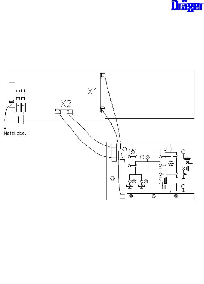
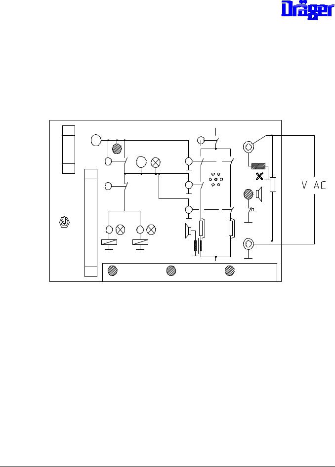
8.1.8.2Preparation of test
The heating unit of Incubators 8000 SC/ICNC can be tested while assembled or disassembled.
Note: |
If the unit is disassembled an isolating transformer must be used. |
Test set-up (Netzkabel = power cord):
PCB Unit (part of the heating unit)
-Interrupt mains connection
-Connect tester to X1 PCB Unit using cable
-Connect tester to X2 PCB Unit, the cable connection to the valve(s) must be interrupted before
-Set all switches at tester to "0" (off)
-Interrupt water supply to boiler of the heating unit
-Attach fan wheel
6141.22x |
Incubator 8000 SC/IC/NC |
Repair Information |
11.99 |
Page 12 of 96 |

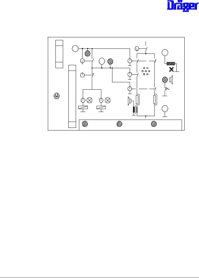
-Establish mains connection to incubator (heating unit installed) respective to heating unit (not installed)
Set switch K1 at tester to "1" (on).
-Action inside the heating unit
o Mains power-up relays K1/K5 (heating unit 82 90 511) on o Fan wheel turns
-Test of tester displays:
o LED + 30 V lights up
o LED 18 V F5 lights up o LED 18 V F6 lights up o LED 9 V F7 lights up
6141.22x |
Incubator 8000 SC/IC/NC |
Repair Information |
11.99 |
Page 13 of 96 |

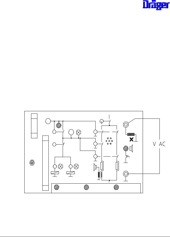
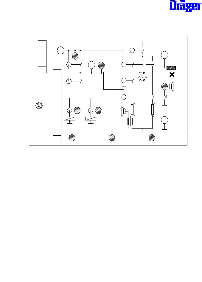
8.1.8.3Test Set-up for testing a Unit in the Field
It is possible to use the following test-up for testing the power unit in the field:
∙open up the unit
∙disconnect the electronic module
∙connect the power unit and the test box with the 40 pin cable
∙carry out the test procedures as given in the following pages (i.e. item 8.1.8.3 and onwards)
Note: The 3 LEDs marked |
in the drawing below are not active in this test-setup. |
Do not connect
40 pin conn.
-Measurement of supply voltages at tester
o alternating voltage 18 V F5 test value: U= 18 V + 15 %
o alternating voltage 18 V F6 test value U = 18 V + 15 %
o alternating voltage 9 V F7 test value U = 9 V + 15 %
6141.22x |
Incubator 8000 SC/IC/NC |
Repair Information |
11.99 |
Page 14 of 96 |

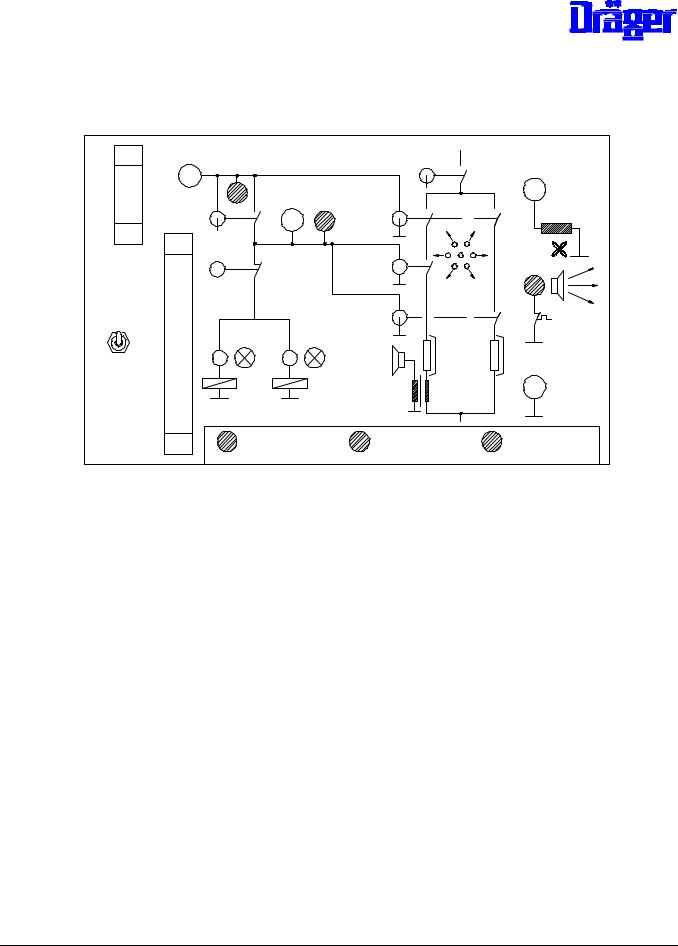
odirect voltage + 30 V test value U = 30 V + 4 V
Possible errors:
Error |
Possible cause |
no reaction after switching of K1 |
- mains input fuses F1/F2 defective |
|
- fuse F3, F9 or F10 of auxiliary mains |
|
transformer defective (F9 and F10 only on |
|
PCB 82 90 511) |
|
- mains power-up relay K1 or. K1/K5 |
|
defective |
|
- fuse F4 for mains transformer |
|
defective |
|
- mains auxiliary transformer or rectifier |
|
behind mains auxiliary transformer on PCB |
|
defective |
|
- Efen sensor of transformer defective |
LED 18 V F5 off or voltage |
- fuse F5 defective |
outside the tolerance |
- transformer defective |
|
- voltage changeover to PCB O.K.? |
LED 18 V F6 off or voltage |
- fuse F6 defective |
outside the tolerance |
- transformer defective |
|
- voltage changeover to PCB O.K.? |
LED 9 V F7 off or voltage |
- fuse F7 defective |
outside the tolerance |
- transformer defective |
|
- voltage changeover to PCB O.K.? |
LED + 30 V off, fan wheel stops |
- fuse F8 defective |
|
- transformer defective |
LED + 30 V off, fan wheel turns |
- rectifier for + 30 V on PCB defective, |
|
alternating voltage exists, because fan wheel |
|
turns |
LED + 30 V lights up, fan wheel |
- fan motor defective |
stops |
- starting capacitor for fan motor defective |
6141.22x |
Incubator 8000 SC/IC/NC |
Repair Information |
11.99 |
Page 15 of 96 |
Troubleshooting:
component to be tested |
test |
fuses |
resistance measurement with disassembled fuses |
mains auxiliary transformer and |
voltage measurement on the PCB via capacitor C2, |
rectifier behind mains auxiliary |
test value approx. 12 V |
transformer |
|
Efen sensor transformer |
If after switch on the voltage on the PCB exists in |
|
front of the transformer, and no LED lights up on the |
|
tester, the transformer must be replaced. The voltage |
|
(mains voltage) is measured on the PCB between the |
|
soldering joint for mains voltage adjustment and fuse |
|
F4. |
8.1.8.4Test of fan monitoring
Prepare test as described in 8.1.8.2, test 8.1.8.3 passed.
Switch K1 at tester set to "1" (on), the fan wheel turns.
Measurement of alternating voltage at tester at socket "feedback fan" and GND.
Test value:
Measurement using an oscilloscope VSS > 2,8 V Peak to Peak
6141.22x |
Incubator 8000 SC/IC/NC |
Repair Information |
11.99 |
Page 16 of 96 |
in this respect only the negative half-wave is important
or (very inaccurate)
Measurement using multimeter: V > 0,6 V
In the case where a high ohm multimeter is used, measure over a 10-20 KOhm resistor as follows:
10-20 K
|
|
|
|
Note: |
Observe service information No. 29 in case of |
||
|
electronics module Incubator 8000 with PCB Motherboard 82 00 850, |
||
|
otherwise an excess output voltage might result in INOP error 9. |
||
6141.22x |
Incubator 8000 SC/IC/NC |
Repair Information |
11.99 |
Page 17 of 96 |

Possible errors:
Error |
possible cause |
Voltage cannot be measured |
- fan wheel properly attached? |
|
- cable connection of PCB to coil of fan |
|
monitoring interrupted |
|
fan monitoring interrupted |
|
- coil of fan monitoring defective |
|
(measure voltage directly at the coil |
|
with the heating unit disassembled) |
voltage too low |
observe service information No. 1 (Inc. |
|
8000SC/IC) and service information No. 31 (Inc. |
|
8000), with Inc. 8000 observe service |
|
information No. 29! |
voltage ok, but continuous fan |
PCB Motherboard in electronics module |
failure alarm at the assembled |
|
incubator |
|
INOP-error 9 with assembled |
voltage too high, observe service information |
Incubator 8000 |
No. 29 for Incubator 8000. In Incubator 8000 |
|
SC/IC this means there is a failure on the PCB |
|
Motherboard. |
6141.22x |
Incubator 8000 SC/IC/NC |
Repair Information |
11.99 |
Page 18 of 96 |
8.1.8.5Test of relay K4
Prepare test as described in 8.1.8.2, test 8.1.8.3 passed.
Switch K1 at tester set to "1" (on), LED "+ 30 V" at tester lights up.
Test:
LED at tester behind switch K4 off
Switch K4 at tester set to "1" (on)
Test:
LED at tester behind switch K4 lights up
Switch K4 at tester set to "0" (off)
Note: |
The voltage behind the switching contacts of relay K4 can be |
|
|
measured at the socket behind switch K4 at the tester. |
|
Possible errors: |
|
|
|
|
|
Error |
|
possible cause |
LED always off or no voltage |
relay K4 defective |
|
LED continuously lights up or voltage exists |
relay K4 defective |
|
continuously |
|
|
6141.22x |
Incubator 8000 SC/IC/NC |
Repair Information |
11.99 |
Page 19 of 96 |
8.1.8.6Test of relay K3
Prepare test as described in 8.1.8.2, tests 8.1.8.3 and 8.1.8.5 passed.
Switch K1 and K4 at tester set to "1" (on), LED "+ 30 V" lights up. Switch V1 and V2 set to "1" (on)
Test: LED V1 and V2 at tester light up.
Switch K3 at tester set to "1" (on)
Test: LED V1 and V2 off
Switch K3 at tester set to "0" (off)
Possible errors:
Error |
possible cause |
LED V1 or V2 continuously light up |
relay K3 defective |
LED V1 or V2 continuously off |
relay K3 defective |
6141.22x |
Incubator 8000 SC/IC/NC |
Repair Information |
11.99 |
Page 20 of 96 |
8.1.8.7Test of relay K2, air heating and feedback air heating
Prepare test as described under 8.1.8.2, tests 8.1.8.3 and 8.1.8.5 passed.
Switch K1 and K4 at tester set to "1" (on)
Switch K2 and HLR1 at tester set to "1" (on)
Test:
Horn (high frequency) in tester on, air heating gets warm (do not allow to become too hot, at 350 °C the thermostatic switch operates)
Switch K2 set to "0" (off), the relay interrupts the power supply to the air heating Test: Horn in tester off
Switch K2 set to "1" (on)
Test: Horn in tester on
Switch HLR1 set to "0" (off), the semiconductor relay of the air heating is switched off Test: Horn in tester off
6141.22x |
Incubator 8000 SC/IC/NC |
Repair Information |
11.99 |
Page 21 of 96 |

Possible errors:
Error |
possible cause |
horn continuously off |
- relay K2 defective |
|
- HLR1 of air heating defective |
|
- air heating defective (highly ohmic) |
|
- thermostatic switch of air heating operates |
|
- feedback defective |
|
(line interrupt) |
horn cannot be switched off with K2 |
relay K2 defective |
horn cannot be switched off with HLR1 |
semiconductor relay HLR1of air heating |
|
defective |
Troubleshooting: |
|
Component to be tested |
Test |
Thermostatic switch air heating |
Resistance measurement approx. 0 Ohm, defective |
|
switches must be replaced |
Air heating |
Resistance measurement, different types of |
|
heating cartridges may be used: |
|
- 132 Ohm (230 V / 240 V) |
|
- 33 Ohm (120V / 127 V) |
|
- 25 Ohm (100V) |
|
- 2 x 60 Ohm (230/115 V) |
Semiconductor relay HLR1 for air |
For this bridge contacts of relay K2 on the PCB via |
heating |
the test points: |
|
- PCB 82 90 511 and PCB 82 00 600 ³ 4: |
|
bridge test points T55 and T57 |
|
- PCB 82 00 600 - 3: |
|
bridge between fuse holder F2 and |
|
solder tag T6 (connection air heating) |
|
Switch on heating via tester (as described in the |
|
test above); however, heating cannot be switched |
|
off via K2. |
Relay K2 |
For this bridge HLR1 of air heating at the mains |
|
side directly at HLR at connections 1 and 2. The |
|
front relay is the HLR for the air heating. |
|
Switch on heating via tester (as described in the |
|
test above), however, the heating cannot be |
|
switched off via K2 |
6141.22x |
Incubator 8000 SC/IC/NC |
Repair Information |
11.99 |
Page 22 of 96 |
8.1.8.8Test of relay K2, water heating and thermostatic switch
Prepare test as described under 8.1.8.2, tests 8.1.8.3 and 8.1.8.5 passed.
Switch K1 and K4 at tester set to "1" (on)
Test: LED "H2O-shortage" shows green light
Switch K2 and HLR2 set to "1" (on)
Test: Boiler gets warm, after approx. 5 to 15 minutes horn on and LED "H2O-shortage" shows red light
Switch HLR2 at tester set to "0" (off)
Test: After 5 minutes max. horn off, LED "H2O-shortage" at tester shows green light again
Repeat all test steps
6141.22x |
Incubator 8000 SC/IC/NC |
Repair Information |
11.99 |
Page 23 of 96 |

Possible errors:
Error |
possible cause |
|
Boiler does not heat up, LED "H2O- |
- excess temperature switch at heating |
|
shortage" continuously shows green |
switched off |
|
light |
- heating cartridge defective (highly ohmic) |
|
|
- relay K2 defective |
|
|
- HLR2 of water heating defective |
|
Boiler heats up, LED "H2O-shortage" |
thermostatic switch water shortage defective |
|
continuously shows green light |
(always closed) |
|
LED "H2O-shortage" continuously shows |
thermostatic switch water shortage defective |
|
red light |
(always open) |
|
Boiler cannot be switched off by means |
HLR2 defective |
|
of switch "HLR2" |
|
|
Troubleshooting: |
|
|
|
|
|
component to be tested |
test |
|
excess temperature switch |
resistance test at resettable thermostatic switch |
|
|
at boiler (approx. 0 Ohm). |
|
|
If switch has operated both thermostatic |
|
|
switches at the boiler must be replaced. |
|
Semiconductor relay HLR2 of water |
For this, bridge contacts of relay K2 on the PCB |
|
heating |
via the test points: |
|
|
- PCB 82 90 511 and PCB 82 00 600 ³ 4: |
|
|
Bridge test points T55 and T58 |
|
|
- PCB 82 00 600 -3: |
|
|
bridge between fuse holder F2 and |
|
|
solder tag T11 (connection water heating) |
|
|
Switch on heating via tester (as described in the |
|
|
test above), however the heating cannot be |
|
|
switched off via K2 |
|
Relay K2 |
For this, bridge HLR2 on the mains side directly |
|
|
at HLR at connection 1 and 2. The HLR of the |
|
|
water heating is the back relay. It must be |
|
|
possible to switch on the heating via the tester, |
|
|
however, it cannot be switched off by means of |
|
|
switch "HLR2", but only with switch K2. |
|
6141.22x |
Incubator 8000 SC/IC/NC |
Repair Information |
11.99 |
Page 24 of 96 |

8.1.8.9Test of heating unit in the incubator
Assemble incubator in operable condition and switch it on.
Test: No INOP or error alarm after switch-on test
Perform O2 calibration (not Inc. 8000 SC/NC) and increase O2-desired value by at least 5 % by vol. compared to actual value
Test: No error-alarm in O2-module
Set humidity desired value to maximum:
Test with water supply:
The humidity measured value rises after a few minutes
Test without water supply:
Water-shortage alarm after a few minutes. The heating is switched off by the control, the boiler cools down and the warning is switched off.
Repeat test several times.
Measurement of power consumption of water heating
Measure power consumption of unit. After self-test briefly withdraw and insert the environmental sensor, thus air heating is suppressed for 90 seconds and with switchedon humidity module and at max. desired value now a pulsating current of approx. 0,5 A (230 V to 240 V-units) or of approx. 1 A (100 V to 127 V-units) can be measured.
Note: By pressing the two desired value buttons in the humidity module switched on for approx. 3 seconds, a "heating LED" can be called up in the humidity module. Thus the control and the pulsating current can be compared.
6141.22x |
Incubator 8000 SC/IC/NC |
Repair Information |
11.99 |
Page 25 of 96 |

8.1.8.10Testing of valves
As a special function the valve of Inc. 8000 IC can be triggered with the tester "heating unit
Inc. 8000".
Prepare test set up as described in 8.1.8.2, but connect valve(s) to X2 on the PCB Unit, the previous cable connection to the tester is no longer used. The LEDs at the tester for "V1", "V2" and the LED behind K4 do not have any function now.
For switch-on set the following switches at the tester to "1" (on): K1, K4 and V1 or V2
8.1.9Voltage Selection
Caution: The electrical height adjustment is only intended for a voltage range of (100 V to 127 V or 220 V to 240 V)! In Incubator 8000 SC/IC/NC also observe mains input fuses!
The following circuit must be modified on the PCB 82 90 511:
-Solder jumper on printed circuit board into desired mains voltage position, refer to
8.1.2 Layout. There are several versions available, therefore the marking for the mains voltages on the printed circuit board shall apply!
-In addition, the following soldering jumpers for the auxiliary transformer need to be
soldered:
220 V to 240 V: soldering jumper T42 ↔ T43
100 V to 127 V: soldering jumpers T41 ↔ T42 and T43 ↔ T44
-Modify fuses on the printed circuit board, refer to 8.1.2.2
The heating cartridge of the air heating must be replaced:
- |
220 |
V to 240 V |
2M 20 329 |
- |
120 |
V /127 V |
2M 20 331 |
- |
100 V |
2M 20 669 |
|
The heating cartridge of the water heating must be replaced:
- |
220 |
V to 240 V |
2M 20 327 |
- |
120 |
V / 127 V |
2M 20 328 |
- |
100 V |
2M 20 668 |
|
6141.22x |
Incubator 8000 SC/IC/NC |
Repair Information |
11.99 |
Page 26 of 96 |

8.1.10Replacement of Unit in the event of Repair
In the event of repair the Units for the Incubators 8000 and 8000 SC/IC/NC can be replaced by the Unit 2M 20 615.
This order number includes heating cartridges, boiler and fuses for 120 V / 127 V. The Unit 2M 20 276 was only intended for one specific mains voltage and is no longer available.
8.1.11Repair Information and Change Status
8.1.11.1Boiler for Inc. 8000 SC/IC in Unit 2M 19 940 for Inc. 8000
The boiler system for Inc. 8000 is considerably easier to service. The boiler housing can be replaced at considerably less cost. For servicing purposes it is still necessary to remove the Unit because the housing of Incubator 8000 has no servicing flap.
The following parts are required for modification:
- |
Boiler modification kit |
2M 20 680 |
|
- |
Boiler (complete) 230 V / 240 V |
2M 20 618 |
or |
-Boiler (complete) 120 V / 127 V 2M 20 619
The modification kit will be available as of approx. September 1993.
6141.22x |
Incubator 8000 SC/IC/NC |
Repair Information |
11.99 |
Page 27 of 96 |

8.2Electronics module
8.2.0Table of Contents
Position of the sub-assemblies in the electronics module:
8.2.5 |
|
8.2.7 |
|
|
|
|
8.2.6 |
8.2.11 |
|
|
8.2.6 |
8.2.11 |
|
|
|
8.2.11 |
|
|
8.2.10 |
8.2.8 |
|
|
|
|
|
|
|
|
|
|
8.2.9 |
8.2.8 |
|
|
|
8.2.3 / 8.2.4 |
8.2.3 |
8.2.3 |
8.2.2 |
8.2.1 (Ink. 8000) |
8.2.1 (Inc.8000 SC/IC)
6141.22x |
Incubator 8000 SC/IC/NC |
Repair Information |
11.99 |
Page 28 of 96 |

8.2.1Keyboards, Inc. 8000 NC/SC/IC
8.2.2PCB Display Air Temperature
8.2.3PCB Display (of options), PCB Display Skin
8.2.4PCB Display Humidity (only Inc. 8000 SC/NC)
8.2.5PCB CPU and Software-Information
8.2.6PCB Analog and PCB Filter
8.2.7PCB Power Pack and Voltage Controller
8.2.8PCB Motherboard and PCB Fan
8.2.9PCB Switch
8.2.10Push Buttons for Height Adjustment (only Inc. 8000)
8.2.11PCB Controller (RS232)
6141.22x |
Incubator 8000 SC/IC/NC |
Repair Information |
11.99 |
Page 29 of 96 |
Loading...