


 Loading...
Air Shields® Isolette® Infant Incubator
WARNING:
For a full understanding of the performance characteristics of this equipment, the user should carefully read this manual before operating.
Models C2000 and C2000e
Operating Instructions

Table of Contents
Section 1: Definitions, Intended Use, and Disclaimer
Definitions . . . . . . . . . . . . . . . . . . . . . . . . . . . . . . . . . . . . . . . . . . . . . . . . . . . . . . . . . . . . . . . . . . . . 1-1
Symbol Definitions . . . . . . . . . . . . . . . . . . . . . . . . . . . . . . . . . . . . . . . . . . . . . . . . . . . . . . . . . . . 1-1
Technical Definitions . . . . . . . . . . . . . . . . . . . . . . . . . . . . . . . . . . . . . . . . . . . . . . . . . . . . . . . . . 1-5
Intended Use . . . . . . . . . . . . . . . . . . . . . . . . . . . . . . . . . . . . . . . . . . . . . . . . . . . . . . . . . . . . . . . . . . . 1-6
Disclaimer . . . . . . . . . . . . . . . . . . . . . . . . . . . . . . . . . . . . . . . . . . . . . . . . . . . . . . . . . . . . . . . . . . . . . 1-7
Section 2: Introduction, Features, and Specifications
Introduction . . . . . . . . . . . . . . . . . . . . . . . . . . . . . . . . . . . . . . . . . . . . . . . . . . . . . . . . . . . . . . . . . . . . 2-1
System Overview . . . . . . . . . . . . . . . . . . . . . . . . . . . . . . . . . . . . . . . . . . . . . . . . . . . . . . . . . . . . 2-1
Humidity System (Optional) . . . . . . . . . . . . . . . . . . . . . . . . . . . . . . . . . . . . . . . . . . . . . . . . . . . . 2-1
Humidity Reservoir . . . . . . . . . . . . . . . . . . . . . . . . . . . . . . . . . . . . . . . . . . . . . . . . . . . . . 2-1
Manifold Assembly . . . . . . . . . . . . . . . . . . . . . . . . . . . . . . . . . . . . . . . . . . . . . . . . . . . . . 2-1
Evaporator Assembly . . . . . . . . . . . . . . . . . . . . . . . . . . . . . . . . . . . . . . . . . . . . . . . . . . . 2-1
Oxygen Control System (Optional) . . . . . . . . . . . . . . . . . . . . . . . . . . . . . . . . . . . . . . . . . . . 2-1
Weighing System (Accessory) . . . . . . . . . . . . . . . . . . . . . . . . . . . . . . . . . . . . . . . . . . . . . . . 2-2
Non-EU Scales . . . . . . . . . . . . . . . . . . . . . . . . . . . . . . . . . . . . . . . . . . . . . . . . . . . . . . . . 2-2
EU Scales . . . . . . . . . . . . . . . . . . . . . . . . . . . . . . . . . . . . . . . . . . . . . . . . . . . . . . . . . . . . 2-2
Uninterruptible Power Supply (UPS) (Optional) . . . . . . . . . . . . . . . . . . . . . . . . . . . . . . . . . 2-2
Functional Description . . . . . . . . . . . . . . . . . . . . . . . . . . . . . . . . . . . . . . . . . . . . . . . . . . . . . . . . 2-3
Air Mode . . . . . . . . . . . . . . . . . . . . . . . . . . . . . . . . . . . . . . . . . . . . . . . . . . . . . . . . . . . . . 2-3
Skin Mode . . . . . . . . . . . . . . . . . . . . . . . . . . . . . . . . . . . . . . . . . . . . . . . . . . . . . . . . . . . . 2-4
Features . . . . . . . . . . . . . . . . . . . . . . . . . . . . . . . . . . . . . . . . . . . . . . . . . . . . . . . . . . . . . . . . . . . . . . . 2-5
Standard Features . . . . . . . . . . . . . . . . . . . . . . . . . . . . . . . . . . . . . . . . . . . . . . . . . . . . . . . . . . . . 2-5
Optional Features . . . . . . . . . . . . . . . . . . . . . . . . . . . . . . . . . . . . . . . . . . . . . . . . . . . . . . . . . . . . 2-5
Accessories . . . . . . . . . . . . . . . . . . . . . . . . . . . . . . . . . . . . . . . . . . . . . . . . . . . . . . . . . . . . . . . . . 2-5
Specifications . . . . . . . . . . . . . . . . . . . . . . . . . . . . . . . . . . . . . . . . . . . . . . . . . . . . . . . . . . . . . . . . . . 2-6
Standard Features . . . . . . . . . . . . . . . . . . . . . . . . . . . . . . . . . . . . . . . . . . . . . . . . . . . . . . . . . . . . 2-6
Options and Accessories . . . . . . . . . . . . . . . . . . . . . . . . . . . . . . . . . . . . . . . . . . . . . . . . . . . . . . . 2-7
Stands . . . . . . . . . . . . . . . . . . . . . . . . . . . . . . . . . . . . . . . . . . . . . . . . . . . . . . . . . . . . . . . . . . 2-7
Humidity System . . . . . . . . . . . . . . . . . . . . . . . . . . . . . . . . . . . . . . . . . . . . . . . . . . . . . . . . . 2-8
Oxygen System . . . . . . . . . . . . . . . . . . . . . . . . . . . . . . . . . . . . . . . . . . . . . . . . . . . . . . . . . . . 2-9
Non-EU Weighing System . . . . . . . . . . . . . . . . . . . . . . . . . . . . . . . . . . . . . . . . . . . . . . . . . . 2-9
EU Weighing System . . . . . . . . . . . . . . . . . . . . . . . . . . . . . . . . . . . . . . . . . . . . . . . . . . . . . . 2-9
Rail Accessory Weight Limitations. . . . . . . . . . . . . . . . . . . . . . . . . . . . . . . . . . . . . . . . . . . 2-10
Non-Rail Accessory Weight Limitations. . . . . . . . . . . . . . . . . . . . . . . . . . . . . . . . . . . . . . . 2-10
Regulations, Standards, and Codes . . . . . . . . . . . . . . . . . . . . . . . . . . . . . . . . . . . . . . . . . . . . . . 2-12
i
Electromagnetic Compatibility (EMC) Guidance and Manufacturer Declarations . . . . . . 2-12
Device Classification . . . . . . . . . . . . . . . . . . . . . . . . . . . . . . . . . . . . . . . . . . . . . . . . . . . . . 2-15
Section 3: Precautions and Safety Tips
Precautions . . . . . . . . . . . . . . . . . . . . . . . . . . . . . . . . . . . . . . . . . . . . . . . . . . . . . . . . . . . . . . . . . . . . 3-1
Electrical Precautions . . . . . . . . . . . . . . . . . . . . . . . . . . . . . . . . . . . . . . . . . . . . . . . . . . . . . . . . . 3-1
Explosion Precautions . . . . . . . . . . . . . . . . . . . . . . . . . . . . . . . . . . . . . . . . . . . . . . . . . . . . . . . . 3-2
EMC Precautions . . . . . . . . . . . . . . . . . . . . . . . . . . . . . . . . . . . . . . . . . . . . . . . . . . . . . . . . . . . . 3-3
Oxygen Precautions . . . . . . . . . . . . . . . . . . . . . . . . . . . . . . . . . . . . . . . . . . . . . . . . . . . . . . . . . . 3-4
Humidity Precautions . . . . . . . . . . . . . . . . . . . . . . . . . . . . . . . . . . . . . . . . . . . . . . . . . . . . . . . . . 3-6
Safety Tips . . . . . . . . . . . . . . . . . . . . . . . . . . . . . . . . . . . . . . . . . . . . . . . . . . . . . . . . . . . . . . . . . . . . 3-7
Section 4: Installation and Operational Checkout |
|
Installation . . . . . . . . . . . . . . . . . . . . . . . . . . . . . . . . . . . . . . . . . . . . . . . . . . . . . . . . . . . . . . . . . . . |
. 4-1 |
Unpackaging . . . . . . . . . . . . . . . . . . . . . . . . . . . . . . . . . . . . . . . . . . . . . . . . . . . . . . . . . . . . . . . |
. 4-2 |
C2000 Stand Assembly . . . . . . . . . . . . . . . . . . . . . . . . . . . . . . . . . . . . . . . . . . . . . . . . . . . . . . . |
. 4-2 |
C2000e Stand Assembly . . . . . . . . . . . . . . . . . . . . . . . . . . . . . . . . . . . . . . . . . . . . . . . . . . . . . . |
. 4-2 |
Rail Assembly and Accessories Installation . . . . . . . . . . . . . . . . . . . . . . . . . . . . . . . . . . . . . . . |
. 4-3 |
Integris (Fairfield Compatible) Rail Assembly . . . . . . . . . . . . . . . . . . . . . . . . . . . . . . . . . |
. 4-3 |
Deutsche Institute von Normen (DIN) Rail Assembly . . . . . . . . . . . . . . . . . . . . . . . . . . . . |
. 4-5 |
Rail Accessories . . . . . . . . . . . . . . . . . . . . . . . . . . . . . . . . . . . . . . . . . . . . . . . . . . . . . . . . . |
. 4-7 |
Hood, Shell, and Stand Assembly . . . . . . . . . . . . . . . . . . . . . . . . . . . . . . . . . . . . . . . . . . . . . . |
. 4-8 |
Mattress Restraint Strap Installation . . . . . . . . . . . . . . . . . . . . . . . . . . . . . . . . . . . . . . . . . . . . . |
. 4-9 |
UPS System Installation . . . . . . . . . . . . . . . . . . . . . . . . . . . . . . . . . . . . . . . . . . . . . . . . . . . . . . |
4-10 |
Weighing System . . . . . . . . . . . . . . . . . . . . . . . . . . . . . . . . . . . . . . . . . . . . . . . . . . . . . . . . . . . |
4-11 |
Non-EU Scale Assembly . . . . . . . . . . . . . . . . . . . . . . . . . . . . . . . . . . . . . . . . . . . . . . . . . . |
4-11 |
EU Scale Assembly . . . . . . . . . . . . . . . . . . . . . . . . . . . . . . . . . . . . . . . . . . . . . . . . . . . . . . |
4-12 |
Humidity System . . . . . . . . . . . . . . . . . . . . . . . . . . . . . . . . . . . . . . . . . . . . . . . . . . . . . . . . . . . |
4-13 |
Oxygen Control System . . . . . . . . . . . . . . . . . . . . . . . . . . . . . . . . . . . . . . . . . . . . . . . . . . . . . . |
4-13 |
Oxygen Sensor Cells . . . . . . . . . . . . . . . . . . . . . . . . . . . . . . . . . . . . . . . . . . . . . . . . . . . . . . |
4-13 |
Oxygen Calibration Fixture . . . . . . . . . . . . . . . . . . . . . . . . . . . . . . . . . . . . . . . . . . . . . . . . |
4-14 |
Operational Checkout . . . . . . . . . . . . . . . . . . . . . . . . . . . . . . . . . . . . . . . . . . . . . . . . . . . . . . . . . . . |
4-15 |
Controller Operational Checkout . . . . . . . . . . . . . . . . . . . . . . . . . . . . . . . . . . . . . . . . . . . . . . . |
4-15 |
Hood/Shell Operational Checkout . . . . . . . . . . . . . . . . . . . . . . . . . . . . . . . . . . . . . . . . . . . . . . |
4-17 |
VHA Stand Operational Checkout . . . . . . . . . . . . . . . . . . . . . . . . . . . . . . . . . . . . . . . . . . . . . . |
4-20 |
UPS System Operational Checkout . . . . . . . . . . . . . . . . . . . . . . . . . . . . . . . . . . . . . . . . . . . . . |
4-21 |
Check On/Off/Test Switch and Low Battery Alarm . . . . . . . . . . . . . . . . . . . . . . . . . . |
4-21 |
Test Battery Back-up Function . . . . . . . . . . . . . . . . . . . . . . . . . . . . . . . . . . . . . . . . . . . |
4-22 |
Rail System Operational Checkout . . . . . . . . . . . . . . . . . . . . . . . . . . . . . . . . . . . . . . . . . . . . . . |
4-22 |
Oxygen Control Module Operational Checkout . . . . . . . . . . . . . . . . . . . . . . . . . . . . . . . . . . . . |
4-22 |
ii
Humidity System Operational Checkout . . . . . . . . . . . . . . . . . . . . . . . . . . . . . . . . . . . . . . . . . 4-23 Weighing System Operational Checkout . . . . . . . . . . . . . . . . . . . . . . . . . . . . . . . . . . . . . . . . . 4-23 Non-EU Scale . . . . . . . . . . . . . . . . . . . . . . . . . . . . . . . . . . . . . . . . . . . . . . . . . . . . . . . . . . . 4-23 EU Scale . . . . . . . . . . . . . . . . . . . . . . . . . . . . . . . . . . . . . . . . . . . . . . . . . . . . . . . . . . . . . . . 4-24
Section 5: Instructions for Use
Controls, Indicators and Connectors . . . . . . . . . . . . . . . . . . . . . . . . . . . . . . . . . . . . . . . . . . . . . . . . . 5-1 Incubator . . . . . . . . . . . . . . . . . . . . . . . . . . . . . . . . . . . . . . . . . . . . . . . . . . . . . . . . . . . . . . . . . . . 5-1 Incubator Controls . . . . . . . . . . . . . . . . . . . . . . . . . . . . . . . . . . . . . . . . . . . . . . . . . . . . . . . . 5-1 Hardkeys . . . . . . . . . . . . . . . . . . . . . . . . . . . . . . . . . . . . . . . . . . . . . . . . . . . . . . . . . . . . . 5-1 Softkeys . . . . . . . . . . . . . . . . . . . . . . . . . . . . . . . . . . . . . . . . . . . . . . . . . . . . . . . . . . . . . 5-2 Incubator Indicators . . . . . . . . . . . . . . . . . . . . . . . . . . . . . . . . . . . . . . . . . . . . . . . . . . . . . . . 5-3 Incubator Connectors . . . . . . . . . . . . . . . . . . . . . . . . . . . . . . . . . . . . . . . . . . . . . . . . . . . . . . 5-4 Controller Interface Connector . . . . . . . . . . . . . . . . . . . . . . . . . . . . . . . . . . . . . . . . . . . . 5-4 Serial Port . . . . . . . . . . . . . . . . . . . . . . . . . . . . . . . . . . . . . . . . . . . . . . . . . . . . . . . . . . . . 5-4
Sensor Module . . . . . . . . . . . . . . . . . . . . . . . . . . . . . . . . . . . . . . . . . . . . . . . . . . . . . . . . . . . . . . 5-5 Sensor Module Controls . . . . . . . . . . . . . . . . . . . . . . . . . . . . . . . . . . . . . . . . . . . . . . . . . . . . 5-5 Sensor Module Indicators . . . . . . . . . . . . . . . . . . . . . . . . . . . . . . . . . . . . . . . . . . . . . . . . . . . 5-5 Sensor Module Connectors . . . . . . . . . . . . . . . . . . . . . . . . . . . . . . . . . . . . . . . . . . . . . . . . . 5-5 Stand . . . . . . . . . . . . . . . . . . . . . . . . . . . . . . . . . . . . . . . . . . . . . . . . . . . . . . . . . . . . . . . . . . . . . . 5-5 Stand Controls . . . . . . . . . . . . . . . . . . . . . . . . . . . . . . . . . . . . . . . . . . . . . . . . . . . . . . . . . . . . 5-5 Main Circuit Breaker . . . . . . . . . . . . . . . . . . . . . . . . . . . . . . . . . . . . . . . . . . . . . . . . . . . 5-5 Foot Pedal Controls . . . . . . . . . . . . . . . . . . . . . . . . . . . . . . . . . . . . . . . . . . . . . . . . . . . . 5-6 Stand Indicators . . . . . . . . . . . . . . . . . . . . . . . . . . . . . . . . . . . . . . . . . . . . . . . . . . . . . . . . . . 5-6 Stand Connectors . . . . . . . . . . . . . . . . . . . . . . . . . . . . . . . . . . . . . . . . . . . . . . . . . . . . . . . . . 5-6 Convenience Outlet . . . . . . . . . . . . . . . . . . . . . . . . . . . . . . . . . . . . . . . . . . . . . . . . . . . . . 5-6 AC Input Connector . . . . . . . . . . . . . . . . . . . . . . . . . . . . . . . . . . . . . . . . . . . . . . . . . . . . 5-6
UPS Electronic Module . . . . . . . . . . . . . . . . . . . . . . . . . . . . . . . . . . . . . . . . . . . . . . . . . . . . . . . 5-7 UPS Electronic Module Controls . . . . . . . . . . . . . . . . . . . . . . . . . . . . . . . . . . . . . . . . . . . . . 5-7 UPS Electronic Module Indicators . . . . . . . . . . . . . . . . . . . . . . . . . . . . . . . . . . . . . . . . . . . . 5-7 UPS Electronic Module Connectors . . . . . . . . . . . . . . . . . . . . . . . . . . . . . . . . . . . . . . . . . . . 5-8
Displays . . . . . . . . . . . . . . . . . . . . . . . . . . . . . . . . . . . . . . . . . . . . . . . . . . . . . . . . . . . . . . . . . . . . . . 5-9 Temperature Window . . . . . . . . . . . . . . . . . . . . . . . . . . . . . . . . . . . . . . . . . . . . . . . . . . . . . 5-9 Trend/Alarm Window . . . . . . . . . . . . . . . . . . . . . . . . . . . . . . . . . . . . . . . . . . . . . . . . . . . . . . 5-9 Humidity Window . . . . . . . . . . . . . . . . . . . . . . . . . . . . . . . . . . . . . . . . . . . . . . . . . . . . . . . . 5-9 Oxygen Window . . . . . . . . . . . . . . . . . . . . . . . . . . . . . . . . . . . . . . . . . . . . . . . . . . . . . . . . . . 5-9
System Displays . . . . . . . . . . . . . . . . . . . . . . . . . . . . . . . . . . . . . . . . . . . . . . . . . . . . . . . . . . . . 5-10 Temperature Displays . . . . . . . . . . . . . . . . . . . . . . . . . . . . . . . . . . . . . . . . . . . . . . . . . . . . . . . . 5-10 Trend Display . . . . . . . . . . . . . . . . . . . . . . . . . . . . . . . . . . . . . . . . . . . . . . . . . . . . . . . . . . . . . . 5-10
iii
Weight Displays . . . . . . . . . . . . . . . . . . . . . . . . . . . . . . . . . . . . . . . . . . . . . . . . . . . . . . . . . . . . |
5-10 |
Oxygen Display . . . . . . . . . . . . . . . . . . . . . . . . . . . . . . . . . . . . . . . . . . . . . . . . . . . . . . . . . . . . |
5-11 |
Humidity Display . . . . . . . . . . . . . . . . . . . . . . . . . . . . . . . . . . . . . . . . . . . . . . . . . . . . . . . . . . . |
5-11 |
Factory Default Settings . . . . . . . . . . . . . . . . . . . . . . . . . . . . . . . . . . . . . . . . . . . . . . . . . . . . . . . . . |
5-12 |
Alarms . . . . . . . . . . . . . . . . . . . . . . . . . . . . . . . . . . . . . . . . . . . . . . . . . . . . . . . . . . . . . . . . . . . . . . . |
5-13 |
System Alarms . . . . . . . . . . . . . . . . . . . . . . . . . . . . . . . . . . . . . . . . . . . . . . . . . . . . . . . . . . . . . |
5-13 |
UPS Alarms . . . . . . . . . . . . . . . . . . . . . . . . . . . . . . . . . . . . . . . . . . . . . . . . . . . . . . . . . . . . . . . |
5-17 |
System Prompts . . . . . . . . . . . . . . . . . . . . . . . . . . . . . . . . . . . . . . . . . . . . . . . . . . . . . . . . . . . . . . . |
5-17 |
Infant Placement . . . . . . . . . . . . . . . . . . . . . . . . . . . . . . . . . . . . . . . . . . . . . . . . . . . . . . . . . . . . . . . |
5-19 |
Operating Instructions . . . . . . . . . . . . . . . . . . . . . . . . . . . . . . . . . . . . . . . . . . . . . . . . . . . . . . . . . . . |
5-20 |
System Start-Up and Shut-Down . . . . . . . . . . . . . . . . . . . . . . . . . . . . . . . . . . . . . . . . . . . . . . . |
5-20 |
System Start-up . . . . . . . . . . . . . . . . . . . . . . . . . . . . . . . . . . . . . . . . . . . . . . . . . . . . . . . . . . |
5-20 |
Initial Start-up for systems without UPS . . . . . . . . . . . . . . . . . . . . . . . . . . . . . . . . . . . |
5-20 |
Initial Start-up for systems with UPS (Model C2000e only) . . . . . . . . . . . . . . . . . . . . |
5-20 |
Recovery from Power Failure for non-UPS systems . . . . . . . . . . . . . . . . . . . . . . . . . . |
5-21 |
Recovery from Power Failure for UPS systems (Model C2000e only) . . . . . . . . . . . . |
5-21 |
System Shut Down . . . . . . . . . . . . . . . . . . . . . . . . . . . . . . . . . . . . . . . . . . . . . . . . . . . . . . . |
5-21 |
System Configuration . . . . . . . . . . . . . . . . . . . . . . . . . . . . . . . . . . . . . . . . . . . . . . . . . . . . . . . . |
5-22 |
Variable Height Adjustment . . . . . . . . . . . . . . . . . . . . . . . . . . . . . . . . . . . . . . . . . . . . . . . . . . . |
5-23 |
Temperature Settings . . . . . . . . . . . . . . . . . . . . . . . . . . . . . . . . . . . . . . . . . . . . . . . . . . . . . . . . |
5-23 |
Air Mode . . . . . . . . . . . . . . . . . . . . . . . . . . . . . . . . . . . . . . . . . . . . . . . . . . . . . . . . . . . . . . |
5-24 |
Skin Mode . . . . . . . . . . . . . . . . . . . . . . . . . . . . . . . . . . . . . . . . . . . . . . . . . . . . . . . . . . . . . . |
5-24 |
Controller Screen Settings . . . . . . . . . . . . . . . . . . . . . . . . . . . . . . . . . . . . . . . . . . . . . . . . . . . . |
5-25 |
Skin Probe Attachment . . . . . . . . . . . . . . . . . . . . . . . . . . . . . . . . . . . . . . . . . . . . . . . . . . . . . . . |
5-26 |
Single Temperature Monitoring . . . . . . . . . . . . . . . . . . . . . . . . . . . . . . . . . . . . . . . . . . |
5-26 |
Dual Temperature Monitoring . . . . . . . . . . . . . . . . . . . . . . . . . . . . . . . . . . . . . . . . . . . |
5-27 |
Data Trends . . . . . . . . . . . . . . . . . . . . . . . . . . . . . . . . . . . . . . . . . . . . . . . . . . . . . . . . . . . . . . . . |
5-27 |
Scale Measurements . . . . . . . . . . . . . . . . . . . . . . . . . . . . . . . . . . . . . . . . . . . . . . . . . . . . . . . . . |
5-28 |
Non-EU Scale Measurements . . . . . . . . . . . . . . . . . . . . . . . . . . . . . . . . . . . . . . . . . . . . . . . |
5-28 |
Initial Weigh . . . . . . . . . . . . . . . . . . . . . . . . . . . . . . . . . . . . . . . . . . . . . . . . . . . . . . . . |
5-28 |
Re-weigh . . . . . . . . . . . . . . . . . . . . . . . . . . . . . . . . . . . . . . . . . . . . . . . . . . . . . . . . . . . . |
5-29 |
EU Scale Measurements . . . . . . . . . . . . . . . . . . . . . . . . . . . . . . . . . . . . . . . . . . . . . . . . . . . |
5-29 |
Oxygen Control . . . . . . . . . . . . . . . . . . . . . . . . . . . . . . . . . . . . . . . . . . . . . . . . . . . . . . . . . . . . |
5-30 |
Oxygen Mode . . . . . . . . . . . . . . . . . . . . . . . . . . . . . . . . . . . . . . . . . . . . . . . . . . . . . . . . . . . |
5-30 |
Oxygen Control Set Point . . . . . . . . . . . . . . . . . . . . . . . . . . . . . . . . . . . . . . . . . . . . . . . . . . |
5-31 |
Humidity Settings . . . . . . . . . . . . . . . . . . . . . . . . . . . . . . . . . . . . . . . . . . . . . . . . . . . . . . . . . . |
5-31 |
Humidity Mode . . . . . . . . . . . . . . . . . . . . . . . . . . . . . . . . . . . . . . . . . . . . . . . . . . . . . . . . . . |
5-31 |
Humidity Control Set Point . . . . . . . . . . . . . . . . . . . . . . . . . . . . . . . . . . . . . . . . . . . . . . . . |
5-32 |
iv
VueLink™ Monitoring . . . . . . . . . . . . . . . . . . . . . . . . . . . . . . . . . . . . . . . . . . . . . . . . . . . . . . . 5-32 X-Ray Tray Usage . . . . . . . . . . . . . . . . . . . . . . . . . . . . . . . . . . . . . . . . . . . . . . . . . . . . . . . . . . 5-33 Non-Servo Control Oxygen Usage . . . . . . . . . . . . . . . . . . . . . . . . . . . . . . . . . . . . . . . . . . . . . . 5-33 Calibration . . . . . . . . . . . . . . . . . . . . . . . . . . . . . . . . . . . . . . . . . . . . . . . . . . . . . . . . . . . . . . . . . . . 5-34 Scale Calibration for the Non-EU Scale . . . . . . . . . . . . . . . . . . . . . . . . . . . . . . . . . . . . . . . . . . 5-34 Oxygen Sensor Calibration . . . . . . . . . . . . . . . . . . . . . . . . . . . . . . . . . . . . . . . . . . . . . . . . . . . . 5-36 Oxygen Sensor Calibration to Room Air (21%) . . . . . . . . . . . . . . . . . . . . . . . . . . . . . . . . . 5-36 Oxygen Sensor Calibration to 100% Oxygen . . . . . . . . . . . . . . . . . . . . . . . . . . . . . . . . . . . 5-37 Patient Transport . . . . . . . . . . . . . . . . . . . . . . . . . . . . . . . . . . . . . . . . . . . . . . . . . . . . . . . . . 5-38
Section 6:Cleaning, Maintenance, and Replacement Parts
Cleaning . . . . . . . . . . . . . . . . . . . . . . . . . . . . . . . . . . . . . . . . . . . . . . . . . . . . . . . . . . . . . . . . . . . . . . 6-1 General Cleaning . . . . . . . . . . . . . . . . . . . . . . . . . . . . . . . . . . . . . . . . . . . . . . . . . . . . . . . . . . . . 6-1 Steam Cleaning . . . . . . . . . . . . . . . . . . . . . . . . . . . . . . . . . . . . . . . . . . . . . . . . . . . . . . . . . . . . . . 6-2 Stain Cleaning . . . . . . . . . . . . . . . . . . . . . . . . . . . . . . . . . . . . . . . . . . . . . . . . . . . . . . . . . . . . . . 6-2 Disinfecting . . . . . . . . . . . . . . . . . . . . . . . . . . . . . . . . . . . . . . . . . . . . . . . . . . . . . . . . . . . . . . . . . 6-2 Disassembly for Cleaning . . . . . . . . . . . . . . . . . . . . . . . . . . . . . . . . . . . . . . . . . . . . . . . . . . . . . . 6-2
Mattress Tray, X-Ray Tray, Main Deck, Scale (optional) . . . . . . . . . . . . . . . . . . . . . . . 6-3 Heater and Impeller . . . . . . . . . . . . . . . . . . . . . . . . . . . . . . . . . . . . . . . . . . . . . . . . . . . . 6-3 Humidity Tray and Reservoir (Non-CPC). . . . . . . . . . . . . . . . . . . . . . . . . . . . . . . . . . . . 6-3 Humidity Tray and Reservoir (CPC) . . . . . . . . . . . . . . . . . . . . . . . . . . . . . . . . . . . . . . . . 6-4 Access Door Gaskets, Tubing, Iris Entry Port Sleeves, Cuffs . . . . . . . . . . . . . . . . . . . . 6-4 Air Intake Microfilter . . . . . . . . . . . . . . . . . . . . . . . . . . . . . . . . . . . . . . . . . . . . . . . . . . . 6-4
Cleaning Procedures . . . . . . . . . . . . . . . . . . . . . . . . . . . . . . . . . . . . . . . . . . . . . . . . . . . . . . . . . . 6-4 Reusable Skin Temperature Probe . . . . . . . . . . . . . . . . . . . . . . . . . . . . . . . . . . . . . . . . . . . . 6-4 Access Door Gaskets and Tubing Access Ports . . . . . . . . . . . . . . . . . . . . . . . . . . . . . . . . . . 6-4 Controller, Shell, and Stand . . . . . . . . . . . . . . . . . . . . . . . . . . . . . . . . . . . . . . . . . . . . . . . . . 6-4 Sensor Module, Hood, and Inner Walls . . . . . . . . . . . . . . . . . . . . . . . . . . . . . . . . . . . . . . . . 6-5 Heater Radiator and Fan Impeller . . . . . . . . . . . . . . . . . . . . . . . . . . . . . . . . . . . . . . . . . . . . . 6-5 Humidity Reservoir . . . . . . . . . . . . . . . . . . . . . . . . . . . . . . . . . . . . . . . . . . . . . . . . . . . . . . . . 6-6 Air Intake Microfilter . . . . . . . . . . . . . . . . . . . . . . . . . . . . . . . . . . . . . . . . . . . . . . . . . . . . . . 6-6
Base Covers, Rail and Accessories, Drawers, Tank Mounts,
Monitor Shelf, and I.V. Pole . . . . . . . . . . . . . . . . . . . . . . . . . . . . . . . . . . . . . . . . . . . . . . . . . 6-6
Mattress, Mattress Tray, X-Ray Tray, Main Deck, Heater/Impeller Cover,
Scale (Optional), and Mattress Tilt Bars . . . . . . . . . . . . . . . . . . . . . . . . . . . . . . . . . . . . . . . 6-7 Uninterruptible Power Supply (UPS) Air Filter . . . . . . . . . . . . . . . . . . . . . . . . . . . . . . . . . . 6-7 Reassembly After Cleaning . . . . . . . . . . . . . . . . . . . . . . . . . . . . . . . . . . . . . . . . . . . . . . . . . . . . 6-7 Disposal . . . . . . . . . . . . . . . . . . . . . . . . . . . . . . . . . . . . . . . . . . . . . . . . . . . . . . . . . . . . . . . . . . . 6-9 Maintenance . . . . . . . . . . . . . . . . . . . . . . . . . . . . . . . . . . . . . . . . . . . . . . . . . . . . . . . . . . . . . . . . . . 6-10
v
UPS Battery Pack Maintenance . . . . . . . . . . . . . . . . . . . . . . . . . . . . . . . . . . . . . . . . . . . . . . . . 6-10
UPS Electronics Module Maintenance . . . . . . . . . . . . . . . . . . . . . . . . . . . . . . . . . . . . . . . . . . . 6-11
Air Intake Microfilter Maintenance . . . . . . . . . . . . . . . . . . . . . . . . . . . . . . . . . . . . . . . . . . . . . 6-11
Replacement Parts . . . . . . . . . . . . . . . . . . . . . . . . . . . . . . . . . . . . . . . . . . . . . . . . . . . . . . . . . . . . . . 6-12
Section 7: Troubleshooting 1
General . . . . . . . . . . . . . . . . . . . . . . . . . . . . . . . . . . . . . . . . . . . . . . . . . . . . . . . . . . . . . . . . . . . . . . . 7-1
Symptom, Cause, and Remedy . . . . . . . . . . . . . . . . . . . . . . . . . . . . . . . . . . . . . . . . . . . . . . . . . . . . . 7-1
vi

Section 1
Definitions, Intended Use,
and Disclaimer
Definitions
This manual contains different typefaces and icons designed to improve readability and increase understanding of its content. Note the following examples:
•Standard text—used for regular information.
•Boldface text—emphasizes a word or phrase.
•NOTE:—sets apart special information or important instruction clarification.
The Definitions subsection contains label symbol definitions and technical definitions. Additional definitions of system symbols and icons are located in Section 5 (see “Controls, Indicators, and Connectors” on page 5-1).
Some of the warnings contained in this user manual include number tags or bracketed wording (for example [6.8.2.9] or [IHA025]). These are requirements, which are used solely for internal documentation purposes.
Symbol Definitions
• The symbol below highlights a WARNING or CAUTION:
Warning and Caution
–A WARNING identifies situations or actions that may affect patient or user safety. Disregarding a warning could result in patient or user injury.
–A CAUTION points out special procedures or precautions that personnel must follow to avoid equipment damage.
•The symbol below highlights an ELECTRICAL SHOCK HAZARD WARNING:
Electrical Shock Hazard Warning
1 - 1

• The symbol below indicates “Attention: Consult accompanying documents:”
Attention: Consult Accompanying Documents
• The symbol below indicates a “Type BF applied part:”
Type BF Applied Part
–The instrument provides a specified degree of protection against electric shock, particularly the leakage current and reliability of the protective ground connection with a BF-type applied part.
–A BF-type applied part indicates an applied part isolated from all other parts of the instrument to such a degree that the patient leakage current allowable in a single-fault condition is not exceeded.
•The symbol below indicates “AC power:”
AC Power
• The symbol below indicates “Protective earth (ground):”
Protective Earth (Ground)
• The symbol below indicates “Caution: Hot surface:”
Caution: Hot Surface
• The symbol below indicates “Weight limit:”
Weight Limit
1 - 2
• The symbol below indicates “Consult Accompanying Document on the Battery Weight:”
Battery Weight
• The symbol below indicates “Consult Accompanying Document on Battery Pack Orientation:”
Battery Pack Orientation
• The symbol below indicates “Power Failure:”
Power Failure
• The symbol below indicates “Lock casters when parked on an incline:”
Lock Casters
• The symbol below indicates an ELECTROSTATIC DISCHARGE (ESD) sensitive part:
Electrostatic Discharge (ESD) Sensitive Part
1 - 3
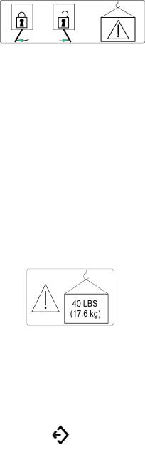
•The symbol below indicates “Consult accompanying documents on latch lock/unlock and rail loading:”
Latch Lock/Unlock and Rail Loading
• The symbol below indicates “Electromagnetic interference:”
Electromagnetic Interference
Interference can occur in the vicinity of the equipment marked with the Electromagnetic Interference symbol.
• The symbol below indicates “Consult accompanying document on the large tray loading:” large Tray Loading
• The symbol below indicates a “Communication port:”
Communication Port
1 - 4

Technical Definitions
•Incubator temperature—Air temperature at a point 4" (10 cm) above and centered over the mattress surface.
•Control temperature—The temperature controller set point selected by the user.
•Average incubator temperature—The average of the maximum and minimum incubator temperatures achieved during temperature equilibrium.
•Incubator temperature equilibrium—The condition reached when the average temperature of the incubator does not vary more than 1°C over a period of 1 hour.
•Temperature uniformity—The amount by which the average temperatures at each of four points 4" (10 cm) above the mattress surface differs from the average incubator temperature at incubator temperature equilibrium.
•Temperature variability—The variability of the incubator temperature that will be observed over a 1- hour period after incubator temperature equilibrium has been reached.
•Temperature rise time—The time required for the incubator temperature to rise 20°F (11°C), when the air control temperature is at least 22°F (12°C) above the ambient temperature.
•Temperature overshoot—The amount by which the incubator temperature exceeds the average incubator temperature at incubator temperature equilibrium as a result of an increase in control temperature.
•Temperature correlation—Temperature indicator versus incubator temperature—The amount the air temperature indicator at incubator temperature equilibrium differs from the incubator temperature.
•Control correlation—Incubator temperature versus control temperature—The amount the average incubator temperature in Air mode at incubator temperature equilibrium differs from the control temperature.
•Control accuracy—Temperature indicator versus control temperature—The amount the air temperature indicator in Air mode at incubator temperature equilibrium differs from the control temperature.
•Measurement points—Measurements are taken at five points in a plane parallel to and 4" (10 cm) above the mattress surface. One point is 4" (10 cm) above the center of the mattress, the remaining four points are the centers of the four areas formed by lines that divide both the width and length in two parts.
1 - 5

Intended Use
This manual provides an overall functional description and the instructions for use of the Isolette® Infant Incubator, Models C2000 and C2000e.
The Isolette® Infant Incubator, Models C2000 and C2000e should be used only by appropriately trained personnel and under the direction of qualified medical personnel.
1 - 6

Disclaimer
Dräger Medical cannot be responsible for the performance of the incubator if the user does not operate the unit in accordance with the instructions, fails to follow the maintenance recommendations, or makes any repairs with unauthorized components. Only qualified service personnel should calibrate and repair it. Technical information is available through local distributors.
All personnel working with the unit should read, thoroughly understand, and have ready access to this manual. Store the manual with the incubator when not in use. Please contact your local representative for clarity or further information.
1 - 7

Notes:
1 - 8

Section 2
Introduction, Features,
and Specifications
Introduction
The Introduction subsection provides a system overview and functional description of the Isolette® Infant Incubator, Models C2000 and C2000e.
System Overview
The Isolette® Infant Incubator, Models C2000 and C2000e is a modular controller-based incubator, which enables simultaneous control of temperature, oxygen, and humidity parameters affecting the infant. The incubator hood and shell assemblies are mounted on a variable height adjustable (VHA) stand or fixed height (FH) stand.
The Isolette® Infant Incubator, Models C2000 and C2000e supports electro luminescent (EL) and liquid crystal display (LCD) display technology.
Humidity System (Optional)
When installed, the built-in humidifier provides humidification of the incubator from 30% to 95% relative humidity (RH) in 1% increments. When the humidity system senses an absence of water an audible and visual Low Humidity alarm occurs. The humidifier is a three-part system consisting of a humidity reservoir, manifold assembly, and evaporator assembly.
Humidity Reservoir
The humidity reservoir has a 1 liter capacity. The reservoir permits visual inspection of the water level. It is located in a drawer in the front of the incubator shell. When the drawer is closed and the latching handle is engaged, the reservoir is connected to a manifold.
Manifold Assembly
The manifold assembly allows the water to flow into the metering valve and the evaporator assembly.
Evaporator Assembly
The metering valve regulates the flow of water to the evaporator chamber to maintain a constant level of water, ensuring optimum responsiveness of the evaporator heater. The evaporator assembly raises the temperature of the water to the boiling point, causing vaporization. Any waterborne bacteria are killed, preventing transfer into the patient compartment. The rate of vaporization is determined by the level of power transmitted to the evaporator heater. The sensor module located within the hood environment houses the humidity sensor, which sends information to the controller module. The controller module regulates the output of the evaporator.
Oxygen Control System (Optional)
When installed, the oxygen (servo) control system adjusts the flow of oxygen within the incubator hood with a valve and an oxygen sensor module. The sensor module houses two independent oxygen fuel cells.
2 - 1
When the sensor module is outside of the hood during Oxygen Control mode, audible and visual alarms are enabled and the flow of oxygen is interrupted.
Weighing System (Accessory)
When installed, the weighing system is located in a platform under the mattress. The scale contains two load beams, which perform the actual weighing function. The controller processes the load beam information and displays the weight in kilograms or pounds in the Trend/Alarm window.
System prompts are displayed in the Trend/Alarm window during the weighing procedure.
Non-EU Scales
The Weight softkey allows for repeated re-weighing of the infant after the weighing routine has been initiated.
EU Scales
Since the weighing routine is continuous, no re-weigh function is required to update the weight measurements.
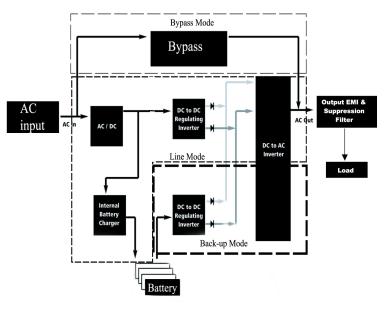
Uninterruptible Power Supply (UPS) (Optional)
When installed, the UPS system provides an on-line uninterruptible back-up power supply to the incubator, which can also be used for intra-facility transport.
With batteries fully charged, the power available from battery backup is sufficient to maintain a C2000e incubator in operation for 30 min in a 20°C ambient at a set point of 39°C in the Air mode, without oxygen or humidity control, or additional loads drawn from the accessory outlets.
Battery back-up usage occurs during power failure or while transporting an unplugged incubator within the facility.
The UPS system consists of two main components: the electronics control module and the battery pack module. The battery pack module consists of three sealed gel cell batteries that are charged by the electronics module. The electronics module is responsible for monitoring, distributing, and controlling the power delivered to the incubator.
The UPS system operates in three modes: line, back-up and bypass. Refer to the table below:
Modes |
Operating Conditions |
|
|
Line |
AC input normal; load range acceptable; inverter (DC to AC) operational |
Back-up |
Loss of AC input; load range acceptable; inverter operational |
Bypass |
Loss of inverter output; acceptable load; power supplied from AC only |
2 - 2

Functional Description
The temperature, humidity, and oxygen concentration is controlled by the forced air circulation system. A controlled amount of room air, approximately 7 lpm, is drawn through the air intake filter by the motor-driven impeller located in the shell.
The impeller internally recirculates air at a much greater flow than that of the fresh gas inflow. The total inflow of fresh and re-circulated air is directed around the heater. The air enters the infant compartment up through the slots at the front and rear of the main deck. It then passes between the front and rear inner walls. The air circulates past the sensor module containing the temperature sensing probe, which encapsulates the air temperature control thermistor and a high air temperature alarm thermistor. After circulating
within the infant compartment, the air is then re-circulated down through a slot in the right end of the main deck, and back to the impeller. When the front and/or rear access panel(s) of the hood is/are open, the air continues to flow upward past the opening, creating a warm air curtain. This curtain minimizes the drop in air temperature within the incubator.
Temperature is regulated by using either incubator air or skin temperature. The front panel keys enable the user to select the desired Air or Skin mode.
In either mode of operation, the heater output is proportional to the amount of heat required to maintain the desired temperature. The Air and Skin modes are described below.
Air Mode
In the Air mode, the air temperature can be maintained from 20.0°C (68.0°F) to 37.0°C (98.6°F) as selected by the Up and Down Arrow keys on the front panel. In Temperature Override mode, the temperature can be maintained from 37.0°C (98.6.0°F) to 39.0°C (102.2°F).
The incubator air temperature is monitored by a probe located in the sensor module and compared with the air set temperature parameter. The information from this probe is supplied to the heater control circuitry, which regulates the heater output to maintain the air temperature setting. The actual air temperature is shown in the Temperature window. A second sensor within the air temperature probe serves as a backup to limit the maximum incubator temperature. If the high temperature limit is reached, the heater shuts off.
The infant temperature is a function of: 1) the air temperature and 2) the ability of the infant to establish and maintain his/her own temperature. A small infant, or one with underdeveloped homeostatic control, may not be able to maintain a stable temperature at the desired level.
2 - 3
Skin Mode
In the Skin mode, the Up and Down Arrow keys on the controller front panel are used to select the infant temperature from 34.0°C (93.2°F) to 37.0°C (98.6°F). In Temperature Override mode, the temperature can be selected from 37.0°C (98.6°F) to 38.0°C (100.4°F).
A temperature sensing probe is attached directly to the skin of the infant. The information from the probe is supplied to the heater control circuitry, which proportions the heater output to maintain the skin set temperature.
The air temperature is still shown in Skin mode, but for information purposes only. If the Air mode is selected while the skin probe remains connected, the skin temperature parameter continues to display the actual skin temperature. However, it does not control the incubator temperature.
The sensor module is equipped to accept two skin probes. To control the incubator temperature in the skin mode, insert a skin probe into the skin probe 1 connector (see “Controls, Indicators, and Connectors” on page 5-1). When a second skin probe is connected to the sensor module while operating in the skin mode, an alarm sounds and the message Remove Skin 2 Probe is displayed. To connect a second skin probe, select the Air mode first. The controller then displays the respective Skin 1 and Skin 2 temperatures monitored by the skin probes.
If Probe 1 is disconnected from its receptacle while in the Skin mode, the skin temperature parameter goes blank on the display, an alarm sounds, and the heater turns off.
2 - 4
Features
The Features subsection provides a list of the standard and optional features and available accessories for the Isolette® Infant Incubator, Models C2000 and C2000e.
Standard Features
Standard features include:
•Oval access doors with a quiet latch
•Trendelenberg mattress tilt mechanism (0° to 12°)
•Pedestal base cover (C2000e, only)
•Rail system (C2000e, only)
Optional Features
Options include:
•Oxygen control system
•Humidity system
•Fixed height stand (without UPS system)
•VHA stand (without UPS system) C2000e only
•Fixed height stand (with UPS system)
•VHA stand (with UPS system)
Accessories
Accessories include:
•Weighing system
•Ventilation support
•Temperature probes
•Port sleeves and cuffs
•5 kg weight
•Gas tank mounts and tanks (E and D sizes) C2000e only
•Deutsche Institute von Normen (DIN) and Integris/Fairfield rail mounted accessories C2000 only
•Non-rail mounted accessories
2 - 5

Specifications
The Specifications subsection provides specifications for the standard and optional features and available accessories of the Isolette® Infant Incubator, Models C2000, and C2000e. It also includes regulation and standards and codes information for the system.
Standard Features
Feature |
Dimension |
|
|
Physical |
|
C2000 |
|
Depth |
67.31 cm (26.5) |
Width |
102.9 cm (40.5'') |
C2000e |
|
Depth |
67.31 cm (26.5") |
Width |
120 cm (47.25'') (including rail width) |
Incubator weight |
≥ 49 kg (108 lb) |
Mattress tray width |
79 cm (31") |
Mattress tray depth |
41 cm (16") |
Mattress Trendelenburg/Reverse |
Continuously variable to 12° ± 1° |
Trendelenburg tilt |
|
Electrical |
|
Convenience outlets |
100V, 50/60 Hz, 300 W maximum |
(Model C2000, 100V, only) |
|
Convenience outlets (120V) |
120V, 50/60 Hz, 300 W maximum |
Convenience outlets (230V) |
230V, 50/60 Hz, 300 W maximum |
Chassis current leakage (100V and 120V) |
≤ 300 µA |
|
|
Chassis current leakage (230V) |
≤ 500 µA |
|
|
Environmental |
|
Air mode control temperature range |
20.0°C (68.0°F) to 37.0°C (98.6°F) |
Air mode control override temperature range |
37.0°C (98.6°F) to 39.0°C (102.2°F) |
Skin mode control temperature range |
34.0°C (93.2°F) to 37.0°C (98.6°F) |
Skin mode control override temperature range |
37.0°C (98.6°F) to 38.0°C (100.4°F) |
Temperature rise time at 22°C (72°F) ambient |
< 35 min |
Temperature variability |
< 0.5°C |
Temperature overshoot |
< 0.5°C maximum |
Temperature uniformity with a level mattress |
< 0.8°C |
Correlation of the indicated air temperature to |
≤ 0.8°C |
the actual incubator temperature (after the |
|
incubator temperature equilibrium is reached) |
|
Environment temperature operating range |
20°C (68°F) to 30°C (86°F) |
Operating temperature—RH sensor |
20°C (68°F) to 41°C (106°F) |
Operating temperature—oxygen sensor |
20°C (68°F) to 41°C (106°F) |
Operating humidity range |
5% to 99% RH non-condensing |
2 - 6

Feature |
Dimension |
|
|
Noise level within the hood environment |
< 47 dBa with 37 dBa or less ambient (less O2 |
|
administration) |
Air velocity over the mattress |
< 4"/second (10 cm/second); average of five points |
|
at 4" (10 cm) above the mattress |
Storage temperature |
-25°C (-13°F) to 60°C (140°F) |
Storage humidity range |
0% to 99% relative humidity non-condensing |
Carbon Dioxide (CO2) level |
<0.5% |
(per EN60601-2-19, Clause 105) |
|
Operational |
|
Set point data retention (non-UPS systems) |
power failures lasting <10 min |
Set point data retention (UPS systems) |
power failures lasting < (battery charge depletion |
|
time + 10 min) |
Options and Accessories
Stands
Feature |
Dimension |
|
|
Physical |
|
Fixed Height Stand |
|
Top of hood to floor (incubator with FH stand) |
142 cm (56") ± 12.7 mm (½") |
Mattress to floor (incubator with FH stand) |
100.97 cm (39¾") ± 12.7 mm (½") |
Weight (without UPS system and accessories) |
49.4 kg (109 lb) |
Variable Height Stand |
|
Top of hood to floor (incubator with VHA |
133.35 cm (52½") ± 12.7 mm (½") to 152 cm (60") |
stand) |
± 12.7 mm (½") |
Mattress to floor (incubator with VHA stand) |
90.17 cm (35½") ± 12.7 mm (½") to 110½" (43½") |
|
± 12.7 mm (½") |
Weight (with UPS system and accessories) |
≤ 97 kg (214 lb) |
|
|
UPS |
|
Battery pack weight |
9.5 kg (20.9 lb) |
Electrical |
|
Fixed Height Stand |
|
Power requirements for 100V/120 FH stand |
100 V/120 V, 50/60 Hz, 9.9 A maximum |
(100V for Model C2000, only) |
|
Power requirements for 230V FH stand |
230 V, 50/60 Hz, 9.9 A maximum |
Variable-Height Stand |
|
Power requirements for 100/120V VHA stand |
Without UPS: 100 V/120 V, 50/60 Hz, |
(100V for Model C2000 only) |
9.9 A maximum |
|
With UPS: 120 V, 50/60 Hz, 11 A maximum |
Power requirements for 230V VHA stand |
With and without UPS: 230V, 50/60 Hz, 9.9 A |
model |
maximum |
UPS
2 - 7
Feature |
Dimension |
|
|
Input current breaker rating |
15 A for 120 V; 7A for 230 V |
Output circuit breaker rating |
10 A for 120 V; 5 A for 230 V |
Input frequency |
50/60 Hz (auto sensed by the microprocessor) |
|
45-65 Hz (inverter phase-lock frequency range) |
Battery type |
gel cell |
Operational |
|
UPS charge time |
Full capacity after 8 hours |
UPS operating time |
With batteries fully charged, the power available |
|
from battery backup is sufficient to maintain a |
|
C2000e incubator in operation for 30 min in a |
|
20°C ambient at a set point of 39°C in the Air |
|
mode, without oxygen or humidity control, or |
|
additional loads drawn from the accessory outlets. |
Humidity System |
|
Feature |
Dimension |
|
|
Humidity System |
|
Humidity control operating time without |
24 hours maximum @ 85% RH and 36°C, in Air |
refilling |
mode |
Humidity control reservoir capacity |
1000 ml |
Humidity control range |
30% to 95% in 1% increments (at high ambient |
|
humidity levels, low level humidity settings may |
|
not be attainable) |
Humidity control accuracy between 10% and |
± 6% RH |
90% @ 68°F (20°C) to 104°F (40°C) |
|
Maximum humidity levels |
>85% (incubator set temp at 39°C, with at least |
|
30% RH at ambient) |
2 - 8
Oxygen System
Feature |
Dimension |
|
|
Oxygen Control System |
|
Oxygen inlet pressure |
40 psi to 150 psi |
Oxygen inlet flow rate |
30 liters/min |
Oxygen control range |
21% to 65% |
Oxygen display resolution |
1% increments |
Oxygen control accuracy at 100% |
± 3% |
calibration |
|
Oxygen control accuracy at 21% |
± 5% |
calibration |
|
Non-EU Weighing System |
|
Feature |
Dimension |
|
|
Weighing System |
|
Weight display range |
0 kg (0 lb) to 7 kg (15 lb) |
Weight display resolution |
1.0 g or 0.04 oz |
Weight display accuracy |
0 - 2 kg; 2 g ± ½ digit |
|
> 2 kg; ±5 g ± ½ digit |
Maximum tare weight |
4.0 kg (8.82 lb) ±0.5 kg |
EU Weighing System |
|
Feature |
Dimension |
|
|
Weighing System |
|
Maximum capacity |
7 kg (15lb) |
Minimum capacity |
200 g (.44 lb) |
Maximum tare weight |
4.0 kg (8.82 lb) ± 0.5 kg |
Verification scale interval |
10 g (.022 lb) |
Scale level sensitivity |
90 min (1 min=1/60 degree) |
Weight display accuracy |
10 g (.022 lb) |
Weight display update rate |
1 s |
Weight display resolution |
10 g (.022 lb) |
2 - 9
Rail Accessory Weight Limitations
Feature |
Dimension |
|
|
Rail system assembly |
Total rail accessory weight not to exceed 36.3 kg |
|
(80 lb); 13.1 kg (40 lb) per side rail or 6.8 kg (15 |
|
lb) per front and rear rail (with remaining weight |
|
distributed along side rails) |
Monitor shelf assembly, high/low, C2000e |
11 kg (25 lb) |
I.V. pole assembly, C2000e |
5 kg (11 lb) |
Basket 18.0 W x 9.5 D x 4.0 H |
4.4 kg (10 lb) |
Basket 6.5 W x 4.0 D x 5.0 H |
2.2 kg (5 lb) |
Basket 11.0 W x 4.0 D x 4.0 H |
2.2 kg (5 lb) |
Basket - pivoting |
2.2 kg (5 lb) |
Chart holder |
|
Hinged mayo tray, 13.5 W x 9.75 D |
2.2 kg (5 lb) |
Hinged mayo tray, 17.0 W x 11.5 D |
2.2 kg (5 lb) |
Cable organizer |
2.2 kg (5 lb) |
Horizontal cord wrap |
2.2 kg (5 lb) |
Standard cam adapter |
2.2 kg (5 lb) |
Ball action adapter |
2.2 kg (5 lb) |
Double cam adapter |
2.2 kg (5 lb) |
Cam adapter, threaded mount |
2.2 kg (5 lb) |
Utility hook assembly |
2.2 kg (5 lb) |
Reading lamp |
1.3 kg (2.9 lb) |
NCL examination lamp |
1.7 kg (3.8 lb) |
Holder for litter bags, including 100 litter bags |
0.680 kg (1.5 lb) |
Basket 150, for disposable gloves |
0.346 kg (0.763 lb) |
Basket 300, for 300 mm catheters |
0.433 kg (0.954 lb) |
Basket 600, for 600 mm catheters |
0.635 kg (1.4 lb) |
Tray 3020 |
1.2 kg (2.6 lb) |
Non-Rail Accessory Weight Limitations |
|
Feature |
Dimension |
|
|
Monitor shelf assembly, high, C2000e |
11 kg (25 lb) |
Monitor shelf assembly, low, C2000e |
11 kg (25 lb) |
I.V. pole assembly, C2000e |
5 kg (11 lb) |
Tray assembly, large |
17.6 kg (40 lb) |
Swivel drawer assembly, large |
Tray - 0.91 kg (2 lb) |
|
Drawer - 4.5 kg (10 lb) |
Swivel drawer assembly, small |
Tray - 0.91 kg (2 lb) |
|
Drawer - 2.2 kg (5 lb) |
Swivel drawer assembly, small, C2000e |
Tray - 0.91 kg (2 lb) |
|
Drawer - 2.2 kg (5 lb) |
Drawer housing assembly, shallow, short |
2.2 kg (5 lb) |
2 - 10
Feature |
Dimension |
|
|
Drawer housing assembly, shallow, long |
2.2 kg (5 lb) |
Swivel drawer assembly, large, C2000e |
Tray - 0.91 kg (2 lb) |
|
Drawer - 4.5 kg (10 lb) |
Drawer housing assembly, deep, short |
4.5 kg (10 lb) |
Drawer housing assembly, deep, long |
4.5 kg (10 lb) |
2 - 11

Regulations, Standards, and Codes
The Isolette® Infant Incubator, Models C2000 and C2000e complies with the following safety standards and performance standards:
•EN 60601-1—1990, Medical Electrical Equipment, Part 1: General Requirements for Safety, including Amendments 1 and 2
•EN 60601-1-2—2002, Collateral Standard: Electromagnetic Compatibility—Requirements and Tests
•EN 60601-2-19—1996, Particular Requirements for the Safety of Baby Incubators, including Amendment 1
Electromagnetic Compatibility (EMC) Guidance and Manufacturer Declarations
Guidance and Manufacturer’s Declaration— Emissions
The C2000 is intended for use in the electromagnetic environment specified below. The customer or user of the unit should ensure that the unit is used in such an environment.
Emissions Test |
Compliance |
Electromagnetic Environment—Guidance |
|
|
|
Radio frequency (RF) |
Group 1 |
The C2000 uses RF energy only for its internal |
emissions—CISPR 11 |
|
function. Therefore, its RF emissions are very |
|
|
low and are not likely to cause interference with |
|
|
nearby electronic equipment. |
RF emissions |
Class A |
The C2000 is suitable for use in all establish- |
CISPR 11 |
|
ments, including domestic, and those directly |
|
|
connected to the public low-voltage power sup- |
Harmonics |
Class A |
|
IEC 61000-3-2 |
|
ply network that supplies buildings used for |
|
|
domestic purposes. |
Flicker |
Class A |
|
IEC 61000-3-3 |
|
|
2 - 12

Guidance and Manufacturer’s Declaration—Immunity
The C2000 is intended for use in the electromagnetic environment specified below. The customer or user of the C2000 should ensure that the unit is used in such an environment.
Immunity Test |
IEC 60601 Test |
Compliance Level |
Electromagnetic Environment— |
|
Level |
Guidance |
|||
|
|
|||
|
|
|
|
|
ESD |
± 6 kV contact |
± 6 kV contact |
The floors should be wood, concrete, or |
|
IEC 61000-4-2 |
± 8 kV air |
± 8 kV air |
ceramic tile. If floors are covered with |
|
|
|
|
synthetic, the relative humidity should be |
|
|
|
|
at least 30%. |
|
EFT |
± 2 kV Mains |
± 2 kV Mains |
Mains power quality should be that of a |
|
IEC 61000-4-4 |
± 1 kV I/Os |
No I/Os |
typical commercial or hospital |
|
|
|
|
environment. |
|
Surge |
± 1 kV Differential |
± 1 kV Differential |
Mains power quality should be that of a |
|
IEC 61000-4-5 |
± 2 kV Common |
± 2 kV Common |
typical commercial or hospital |
|
|
|
|
environment. |
|
Voltage Dips/Drop- |
> 95% dip for 0.5 |
> 95% dip for 0.5 |
Mains power quality should be that of a |
|
out |
cycle |
cycle |
typical commercial or hospital |
|
IEC 61000-4-11 |
|
|
environment. If the user of the C2000 |
|
|
60% dip for 5 cycle |
60% dip for 5 cycle |
requires continued operation during power |
|
|
|
|
mains interruptions, it is recommended |
|
|
30% dip in for 25 |
30% dip in for 25 |
that the C2000 be powered from an |
|
|
cycles |
cycles |
uninterruptible power supply or battery. |
|
|
> 95% dip for 5 sec- |
> 95% dip for 5 sec- |
|
|
|
onds |
onds |
|
|
|
|
|
|
|
Power frequency |
3 A/m |
3 A/m |
Power frequency magnetic fields should |
|
50/60 Hz |
|
|
be that of a typical commercial or hospital |
|
Magnetic field |
|
|
environment. |
|
IEC 61000-4-8 |
|
|
|
2 - 13
Guidance and Manufacturer’s Declaration— Immunity
The C2000 is intended for use in the electromagnetic environment specified below. The customer or user of the C2000 should ensure that the unit is used in such an environment.
Immunity |
IEC 60601 |
Compliance |
|
Electromagnetic Environment—Guidance |
|
Test |
Test Level |
Level |
|
|
Recommended Separation Distance |
|
|
|
|
||
|
|
|
Portable and mobile communications equipment should be separated from |
||
|
|
|
the C2000 by no less than the distances calculated/listed below: |
||
Conducted |
3 Vrms (out- |
V1=3 Vrms |
D = 1.167 P outside ISM |
||
RF |
side ISM) |
V2=10 Vrms |
|||
IEC 61000-4- |
20Vrms (in |
|
D = 1.2 |
P in ISM |
|
6 |
ISM bands) |
|
|||
|
150 KHz to |
|
|
|
|
|
80 MHz |
|
|
|
|
|
|
|
|
|
|
Radiated RF |
10 V/m |
E1=10 V/m |
D = 1.2 |
P |
|
IEC 61000-4- |
|
|
80 MHz to 800 MHz |
||
3 |
|
|
|
|
|
80 MHz to |
|
|
|
|
|
|
|
D = 2.3 |
P |
|
|
|
2.5 GHz |
|
800 MHz to 2.5 GHz |
||
|
|
|
|
|
|
|
|
|
where P is the maximum power in watts and D is the recommended |
||
|
|
|
separation distance in meters. |
||
|
|
|
Field strengths from fixed RF transmitters, as determined by an |
||
|
|
|
electromagnetic site survey, should be less than the compliance levels (V1, |
||
|
|
|
V2, and E). |
|
|
Recommended Separations Distances for the C2000
The C2000 is intended for use in the electromagnetic environment in which radiated RF disturbances are controlled. The customer or user of the C2000 can help prevent electromagnetic interference by maintaining a minimum distance between portable and mobile RF Communications Equipment and the C2000 as recommended, according to the maximum output power of the communications equipment.
|
Separation (m) |
Separation (m) |
|
|
Separation (m) |
|
|
150 kHz to |
150 kHz to |
Separation (m) |
|||
Maximum Output |
800 MHz to |
|||||
80 MHz |
80 MHz |
80 to 800 MHz |
||||
Power |
2.5 GHz |
|||||
Non-ISM |
ISM |
|
|
|||
(Watts) |
D = 1.2 |
P |
|
|||
D = 1.167 P |
D = 1.2 P |
D = 2.3 P |
||||
|
|
|
||||
|
|
|
|
|||
|
|
|
|
|
|
|
0.01 |
0.1167 m |
0.12 m |
0.12 m |
|
0.23 m |
|
0.1 |
0.369 m |
0.38 m |
0.38 m |
|
0.73 m |
|
1 |
1.167 m |
1.2 m |
1.2 m |
|
2.3 m |
|
10 |
3.69 m |
3.8 m |
3.8 m |
|
7.3 m |
|
100 |
11.67 m |
12 m |
12 m |
|
23 m |
|
2 - 14
Loading...