


CATALINA 2500
A&E Systems
A&E CATALINA 2500
USA
Service Office
The Dometic Corp.
509 South Poplar St.
LaGrange, IN 46761
CANADA
Dometic Dist.
866 Langs Dr.
Cambridge, Ontario
CANADA N3H 2N7
INSTALLATION & OPERATING
INSTRUCTIONS
REVISION
Form No. 3103624.023 3/98
(Replaces 3103624.015)
(French 3108310.024)
©1998 The Dometic Corporation
LaGrange, IN 46761
1
Catalina
2500
A&E CATALINA 2500
A&E CATALINA 2500
INSTALLATION/OPERATION
APPLICATION
The A&E Catalina 2500 Case Awning is designed and
intended for direct mounting on straight and most curved
mini-motorhomes, pick-up campers, vans, van conversions
and pop-up tent trailers.
The optional Universal Van Adapter Kit, A&E Part No.
930035 allows permanent or temporary mounting to vans
with rain gutters without drilling holes in the van.
Important: Read the entire installation procedure
before starting installation.
Note: The Dometic Corporation assumes no liability for
damages or injuries resulting from installation or operation
of this product.
The Dometic Corporation reserves the right to modify
appearances and specifications without notice.
INSTALLATION
Tools Required:
o Measuring Tape o Pencil
o Electric Drill o Pop Rivet Gun (Necessary
o Drill Bits #& or 3/6, 1/8 only if Backing Plate is
o Center Punch needed)
o Phillips Screw Driver o Silicone Sealant
Note: Awning must be mounted with case back parallel to
side wall of vehicle.
Shim not supplied
NO YES
Note: Be sure to use a dab of silicone sealant on every
screw where a hole has been drilled in the side of the
vehicle. This will prevent possible water leakage.
YES
For Direct Wall Mounting:
Note: When determining location for awning make sure to
consider door clearance, if required, and location of other
vehicle components like compartment doors, mirrors, etc..
1. A. Install C-Channel of awning case into awning rail by
inserting C-Channel into one end of awning rail and
sliding awning case into position (FIG. 1A), or by
tilting case up and inserting entire C-Channel into
awning rail and rotating case down into position
(FIG. 1B).
B. Using the end caps as templates, drill one 1/8 Dia.
hole into vehicle for each end cap (FIG. 1A). Secure
each end cap using one #10 x 3/4 Phillips pan head
sheet metal screw with a small dab of silicone
sealant on each screw (FIG 1A & 1B).
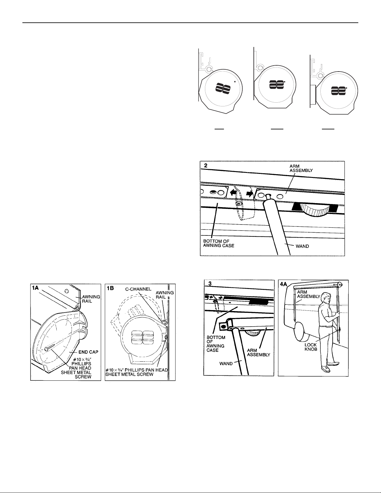
2. Using the wand, open awning case by inserting the pin
on the end of the wand into hole in arm assembly
indicated by arrows on bottom of case (FIG. 2)
3. Lower arm assembly out of awning case (FIG. 3)
4. A. Allow arm to hang freely from case. Tighten lock
knob (FIG. 4A). Repeat for other side.
Note: For curved sided vehicles proceed to Step 4B. For
straight sided vehicles skip to Step 5.
B. Lower arm assembly to ground. With foot still on
ground raise inner arm as high as it will go (FIG. 4B).
2

Note: Make sure lock in top of awning arm assembly clears
top of case lip (FIG. 4C). This is necessary for awning to
open properly.
Tighten lock knob. Repeat steps 4B & 4C for other
side.
C. Using wand, hook pull-strap and pull awning out
about 3 feet (1 meter) (FIG. 4D).
D. While securely holding the pull-strap, tighten the lock
knobs on the rafter arms (FIG. 4E).
A&E CATALINA 2500
Note: Positioning of left and right bottom mounting brackets should be at same level and centered to the awning
arms (FIG. 6).
7. Loosen lock knob and extend arm assembly keeping
arm perpendicular to awning case. Once location is
determined, tighten lock knob (FIG. 7).
Note: The bottom mounting brackets should be mounted to
the floorline of solid structural member whenever possible.
8. Using the foot and bottom mounting bracket as a
template, drill a 1/8 dia. hole for the bottom screw.
Secure bottom mounting bracket with foot attached to
vehicle using a #10 x 1-1/2 long Phillips pan head
sheet metal screw thorough the foot and the bottom
mounting bracket. Use a small dab of silicone sealant
on screw (FIG. 8)
5. Snap awning foot into bottom mounting bracket (FIG.5).
6. Select a location for mounting of bottom mounting
bracket on side of vehicle. The minimum mounting
distance from the bottom of the awning case to the
bottom of the bottom mounting bracket for the 2.5 meter
awning is 48. For the 3.0, 3.5 and 4.0 meter awnings it
is 58 (FIG. 6).
9. A. Release foot from bottom mounting bracket and drill
a 1/8 dia. hole for the top screw. Using a #10 x 1 long
Phillips pan head sheet metal screw with a dab of
silicone sealant on it, secure the top of the bottom
mounting bracket to vehicle (FIG. 9A).
Repeat Steps 5 thorough 9A for other side.
Note: For curved sided vehicles proceed to Step 9B. For
straight sided vehicles skip to Step 10.
B. Loosen lock knob and lower arm assembly to
ground. With foot still on ground raise inner arm as
high as it will go (FIG. 9B).
Note: Make sure lock in top of awning arm assembly clears
top of case lip (FIG. 9C).
3
 Loading...