


B59516
Description
Air Conditioner 457915
Model Use With Air Distribution Box
B57915
459516
B59516
540315
H540315
540316
H540316
640312
640315
640316
RECORD THIS INFORMATION FOR FUTURE
REFERENCE:
Model Number
Serial Number
ADB Model Number
ADB Serial Number
Date Purchased
Roof Top Unit
Model Control
3314851.000 Integral Mechanical
INSTRUCTIONS
INSTALLATION & OPERATING
REVISION E
Form No. 3315079.016 6/18
(French 3315288.013_E)
©2018 Dometic Corporation
LaGrange, IN 46761
Read these instructions carefully. These
instructions MUST stay with this product.
USA & CANADA
SERVICE OFFICE
Dometic Corporation
1120 North Main Street
Elkhart, IN, 46514
SERVICE CENTER &
DEALER LOCATIONS
Please Visit:
www.dometic.com

INTRODUCTION
This air conditioner (hereinafter referred to as “unit” or “product”) is designed and intended for installation on the roof of a
Recreational Vehicle (hereinafter referred to as RV) during or after the time it is manufactured.
This unit can be installed by one person with brief help from additional personnel. Use these instructions to ensure a properly
installed, and properly functioning product.
Dometic Corporation reserves the right to modify appearances and specications without notice.
TABLE OF CONTENTS
INTRODUCTION ..................................................................................................................................................................2
DOCUMENT SYMBOLS.......................................................................................................................................................2
IMPORTANT SAFETY INSTRUCTIONS ............................................................................................................................3
A. Recognize Safety Information ...................................................................................................................................3
B. Understand Signal Words ..........................................................................................................................................3
C. Supplemental Directives ............................................................................................................................................3
D. General Safety Messages .........................................................................................................................................3
SPECIFICATIONS ................................................................................................................................................................4
A. Table - Unit Data ........................................................................................................................................................4
B. Roof Requirements .................................................................................................................................................... 4
INSTALLATION INSTRUCTIONS .......................................................................................................................................4
A. Choosing Proper Location For Unit ...........................................................................................................................4
B. Roof Preparation .......................................................................................................................................................6
C. Wiring Requirements .................................................................................................................................................7
D. Placing Unit On Roof .................................................................................................................................................7
E. Installation Preparation .............................................................................................................................................. 8
F. Duct Divider Installation ............................................................................................................................................. 8
G. Installing Unit ............................................................................................................................................................. 9
H. 120 Vac Power Supply Connection .........................................................................................................................10
I. Installing ADB ..........................................................................................................................................................10
OPERATING INSTRUCTIONS ..........................................................................................................................................12
A. Controls ...................................................................................................................................................................12
B. “OFF” Position ( ) ..................................................................................................................................................12
C. Cooling Operation (Blue Graphic) ........................................................................................................................... 12
D. Heating Operation (With Electric Heater Option Installed). ..................................................................................... 12
E. Fan Operation (Black Graphic) ................................................................................................................................ 12
F. Center Air Discharge ...............................................................................................................................................12
MAINTENANCE ..................................................................................................................................................................13
A. Air Filter ...................................................................................................................................................................13
B. ADB Housing ........................................................................................................................................................... 13
C. Fan Motor ................................................................................................................................................................ 13
GENERAL INFORMATION ................................................................................................................................................13
A. Frost Formation On Cooling Coil ............................................................................................................................. 13
B. Heat Gain ................................................................................................................................................................13
C. Condensation ..........................................................................................................................................................13
D. Air Distribution ......................................................................................................................................................... 13
SERVICE - UNIT DOES NOT OPERATE .........................................................................................................................14
WIRING DIAGRAMS ..........................................................................................................................................................14
A. Unit Wiring Diagrams ............................................................................................................................................... 14
B. ADB Wiring Diagram ...............................................................................................................................................15
DOCUMENT SYMBOLS
Indicates additional information that is NOT related
to physical injury.
Indicates step-by-step instructions.
2

IMPORTANT SAFETY INSTRUCTIONS
This manual has safety information and instructions to help
you eliminate or reduce the risk of accidents and injuries.
A. Recognize Safety Information
This is the safety alert symbol. It is used to
alert you to potential physical injury hazards.
Obey all safety messages that follow this
symbol to avoid possible injury or death.
B. Understand Signal Words
A signal word will identify safety messages and
property damage messages, and will indicate the
degree or level of hazard seriousness.
indicates a hazardous situation that,
if NOT avoided, could result in death or serious injury.
indicates a hazardous situation that,
if NOT avoided, could result in minor or moderate
injury.
is used to address practices NOT
related to physical injury.
C. Supplemental Directives
Read and follow all safety information and
instructions to avoid possible injury or death.
Read and understand these instructions before [installing / using / servicing / performing
maintenance on] this product.
The installation MUST comply with all ap-
plicable local and national codes, including
the latest edition of the following standards:
U.S.A.
● ANSI/NFPA70, National Electrical Code
(NEC)
● ANSI/NFPA 1192, Recreational Vehicles
Code
CANADA
● CSA C22.1, Parts l & ll, Canadian Electri-
cal Code
● CSA Z240 RV Series, Recreational
Vehicles
D. General Safety Messages
Failure to obey the following warnings could result in death or serious injury:
● This product MUST be [installed / serviced] by a
qualied service technician.
● Do NOT modify this product in any way. Modica-
tion can be extremely hazardous.
● Do NOT add any devices or accessories to this
product except those specically authorized in
writing by Dometic Corporation.
Incorrect [installation / operation / servicing /
maintaining] of this product can lead to serious injury. Follow all instructions.
3
SPECIFICATIONS
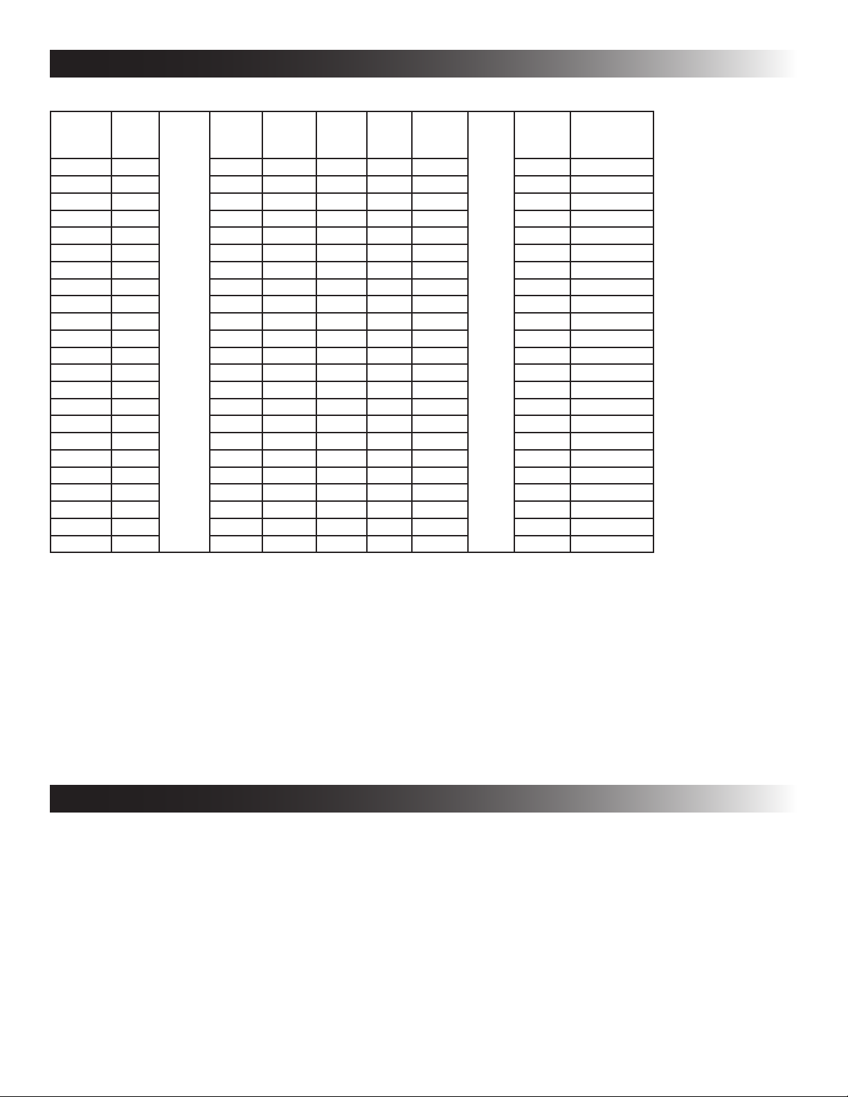
A. Table - Unit Data
Model No. Nominal
457915.70X 13,500 12.4 63.0 2.5 5.8 18.0 20 Amp 3.5 kW / 5.0 kW
457915.71X 13,500 12.4 68.0 2.5 5.8 18.0 20 Amp 3.5 kW / 5.0 kW
B57915.71X 13,500 12.4 68.0 2.5 5.8 18.0 20 Amp 3.5 kW / 5.0 kW
459516.70X 15,000 13.3 66.0 2.0 5.6 27.5 20 Amp 3.5 kW / 5.0 kW
459516.71X 15,000 13.3 70.0 2.0 5.6 27.5 20 Amp 3.5 kW / 5.0 kW
B59516.71X 15,000 13.3 70.0 2.0 5.6 18.3 20 Amp 3.5 kW / 5.0 kW
540315.70X 13,500 12.4 63.0 3.0 8.5 18.5 20 Amp 3.5 kW / 5.0 kW
540315.71X 13,500 12.4 68.0 3.0 8.5 18.5 20 Amp 3.5 kW / 5.0 kW
H540315.72X 13,500 12.7 68.0 2.8 8.0 19.5 20 Amp 3.5 kW / 5.0 kW
540316.70X 15,000 13.3 66.0 2.8 7.6 29.5 20 Amp 3.5 kW / 5.0 kW
540316.71X 15,000 13.3 70.0 2.8 7.6 29.5 20 Amp 3.5 kW / 5.0 kW
H540316.72X 15,000 13.2 70.0 2.8 8.0 20.1 20 Amp 3.5 kW / 5.0 kW
640312.80X 11,000 11.5 53.0 2.6 8.5 20.0 20 Amp 3.5 kW / 5.0 kW
640312.83X 11,000 12.5 63.0 2.6 8.5 18.0 20 Amp 3.5 kW / 5.0 kW
640312C35X 11,000 10.5 53.0 3.5 10.0 19.0 20 Amp 3.5 kW / 5.0 kW
640312C85X 11,000 11.5 53.0 2.6 8.5 20.0 20 Amp 3.5 kW / 5.0 kW
640315.80X 13,500 12.6 63.0 2.6 8.5 18.0 20 Amp 3.5 kW / 5.0 kW
640315.83X 13,500 12.5 63.0 2.6 8.5 19.0 20 Amp 3.5 kW / 5.0 kW
640315.84X 13,500 12.5 63.0 3.5 8.5 19.0 20 Amp 3.5 kW / 5.0 kW
640315C35X 13,500 12.5 61.0 3.5 10.0 17.5 20 Amp 3.5 kW / 5.0 kW
640315C75X 13,500 12.7 52 2.6 8.5 14.5 20 Amp 3.5 kW/ 5.0 kW
640315C85X 13,500 12.6 63.0 2.6 8.5 18.0 20 Amp 3.5 kW / 5.0 kW
640316C75X 15,000 12.9 52 2.6 8.5 21.5 20 Amp 3.5 kW / 5.0 kW
Capacity
(BTU HR)
Cooling
Electrical
Rating
120 Vac
60 Hz 1 ph
Compressor
Rated Load
Amps
Compressor
Locked
Rotor
Amps
Fan Motor
Rated Load
Amps
Fan Motor
Locked
Rotor
Amps
Refrigerant
R-410A
(oz)
Minimum
Wire Size*
12 AWG
Copper
Up to 24'
AC Circuit
Protection
***Installer
Supplied
Minimum
Generator
Size**
1 Unit / 2 Units
* For wire length over 24 ft., consult the National Electrical Code for proper sizing.
** Dometic Corporation gives GENERAL guidelines for generator requirements. These guidelines come from experiences
people have had in actual applications. When sizing the generator, the total power usage of your RV must be considered.
Keep in mind generators lose power at high altitudes and from lack of maintenance.
*** CIRCUIT PROTECTION: Time Delay Fuse or Circuit Breaker Required.
B. Roof Requirements
● A 14-1/4″ x 14-1/4″ (±1/8″) square opening (hereinafter referred to as “roof opening”) is required for installing this
unit. This opening is part of the return air system of the unit and MUST be nished in accordance with NFPA 1192.
● Roof construction with rafters/joists support frames on a minimum of 16 inch centers.
● Minimum of 1.5 inches and maximum of 6 inches distance between roof to ceiling of RV.
INSTALLATION INSTRUCTIONS
A. Choosing Proper Location For Unit
This unit is specically designed for installation on the roof
of an RV. When determining your cooling requirements, the
following should be considered:
● Size of RV;
● Window area (increases heat gain);
● Amount of insulation in walls and roof;
● Geographical location where the RV will be
used;
● Personal comfort level required.
1. Normal locations-The unit is designed to t over
an existing roof vent opening.
4
2. Other locations-When no roof vent is available
or another location is desired, the following is
recommended:
a. For one unit installation: The unit should be
mounted slightly forward of center (front to
back) and centered from side to side.
b. For two unit installations: Install one unit 1/3
and one unit 2/3’s from front of RV and centered from side to side.
It is preferred that the unit be installed on a relatively at
and level roof section measured with the RV parked on a
level surface. See table for maximum acceptable tilt.
INSTALLATION INSTRUCTIONS
Model
Number
457915
B57915
459516
B59516
540315
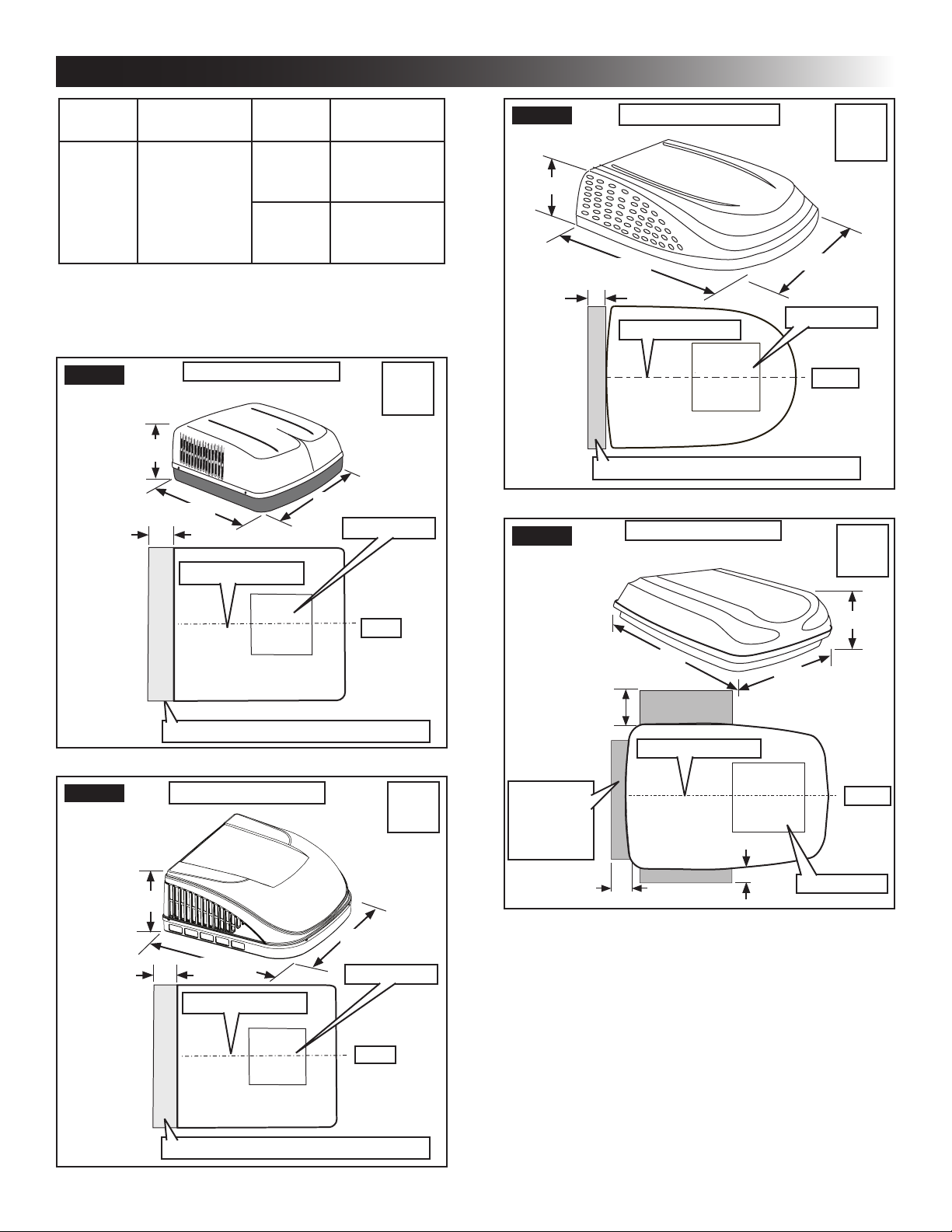
Max Tilt
(All Directions)
15° H540315
Model
Number
540316
H540316
640312
640315
640316
After Location Has Been Selected:
c. Check for obstructions in the area where
unit will be installed. See (FIG. 1), (FIG. 2),
(FIG. 3), (FIG. 4), (FIG. 5) & (FIG. 6).
FIG. 1
13-1/8″
Dimensions Are Nominal
34-7/8″
18″
Center Line Of Unit
Max Tilt
(All Directions)
15°
8°
Model
457915
459516
29-7/8″
Roof Opening
FIG. 3
13″
18″
FIG. 4
Dimensions Are Nominal
39-5/8″
Roof Opening
Center Line Of Unit
Keep This Air Flow Area Free Of Obstructions
Dimensions Are Nominal
Model
540315
540316
29-7/8″
Front
640312
640315
Model
FIG. 2
12-7/8″
Front
Keep This Air Flow Area Free Of Obstructions
Dimensions Are Nominal
27-5/8″
18″
29-5/8″
Center Line Of Unit
Roof Opening
Front
Model
B57915
B59516
Keep These
Air Flow
Areas
Free Of
Obstructions
12″
Center Line Of Unit
4″
40″
4″
9-1/2″
29″
Front
Roof Opening
Keep This Air Flow Area Free Of Obstructions
5
 Loading...