


AWNINGS
POWER AWNING
9200 Model
|
9200 Series Power Awning |
EN |
|
|
Installation Instructions |
|

Power Awning
NORTH AMERICAN ADDRESS INFORMATION
USA & CANADA |
Service Center & Dealer Locations |
Service Office |
Visit: www.dometic.com |
Dometic Corporation |
|
1120 North Main Street |
|
Elkhart, IN 46514 |
|
Form No. 3316600.000_A 7/18 | ©2018 Dometic Corporation
Read these instructions carefully. These instructions MUST stay with this product.
CONTENTS
1 |
Explanation of symbols and safety instructions. . . . . . . . . . . . . . . . . . . . . . . . |
. 3 |
2 |
General information. . . . . . . . . . . . . . . . . . . . . . . . . . . . . . . . . . . |
4 |
3 |
Intended use. . . . . . . . . . . . . . . . . . . . . . . . . . . . . . . . . . . . . . |
5 |
4 |
Specifications. . . . . . . . . . . . . . . . . . . . . . . . . . . . . . . . . . . . . . 5 |
|
5 |
Pre-Installation . . . . . . . . . . . . . . . . . . . . . . . . . . . . . . . . . . . . . 6 |
|
6 |
Installing electric kits. . . . . . . . . . . . . . . . . . . . . . . . . . . . . . . . . . . |
9 |
7 |
Installing the awning. . . . . . . . . . . . . . . . . . . . . . . . . . . . . . . . . . . |
10 |
8 |
Verifying the installation. . . . . . . . . . . . . . . . . . . . . . . . . . . . . . . . . |
16 |
EN |
2 |
|
|

Power Awning
1 EXPLANATION OF SYMBOLS AND SAFETY INSTRUCTIONS
This manual has safety information and instructions to help you eliminate or reduce the risk of accidents and injuries.
1.1 Recognize safety information
This is the safety alert symbol. It is used to alert you to potential physical injury hazards. Obey all safety messages that follow this symbol to avoid possible injury or death.
1.2 Understand signal words
A signal word will identify safety messages and property damage messages, and will indicate the degree or level of hazard seriousness.
indicates a hazardous situation that, if not avoided, could result in death or serious injury. indicates a hazardous situation that, if not avoided, could result in minor or moderate injury.
is used to address practices not related to physical injury.
IIindicates additional information that is not related to physical injury.
1.3 Supplemental directives
Read and follow all safety information and instructions to avoid possible injury or death. Read and understand these instructions before installation of this product.
Incorrect installation of this product can lead to serious injury.
The installation must comply with all applicable local or national codes, including the latest edition of the following standards:
U.S.A. |
Canada |
||
• |
ANSI/NFPA70, National Electrical Code (NEC) |
• |
CSA C22.1, Parts l & ll, Canadian Electrical Code |
• |
ANSI/NFPA 1192, Recreational Vehicles Code |
• |
CSA Z240 RV Series, Recreational Vehicles |
1.4General safety messages
Failure to obey the following warnings could result in death or serious injury:
• This product must be installed and serviced by a qualified service technician.
•IMPACT OR CRUSH HAZARD:
––This awning should be installed in a controlled environment (inside). Do not install the awning during windy conditions, or when wind is expected. Otherwise, the awning could move unpredictably, become unstable, and could detach, bend, or collapse.
––Do not remove LED rail (if equipped) from awning fabric. Otherwise, awning fabric could separate from awning rail (on RV) and cause the awning to extend quickly, resulting in detaching, bending, or collapsing. Failure to obey this warning could result in death or serious injury.
•FIRE OR ELECTRICAL SHOCK HAZARD. Make sure there are no obstacles (wires, pipes, etc.) inside RV walls. Shut OFF gas supply, disconnect 120 VAC power from RV, and disconnect positive (+) 12 VDC terminal from supply battery before drilling or cutting into RV.
•IMPACT OR PINCH HAZARD. Do not remove straps (wrapped around each arm assembly) until roller tube is secured to front channel, awning fabric is attached to awning rail, and arm assembly is mounted to RV. Arm assemblies are under tension from gas strut. Removing these ties could allow arms to extend quickly and unexpectedly. Failure to obey this warning could result in death or serious injury.
3 |
EN |
|
|

Power Awning
LIFTING HAZARD. Use proper lifting technique and control when lifting the awning. Failure to obey this caution could result in injury.
Failure to obey the following notices could damage product or property:
•ALWAYS use sealant on clean parts and surfaces where fasteners enter RV walls. Otherwise, water leakage could occur.
•Install back channels on a flat surface, level, and keep parallel with each other to ensure correct function and appearance.
•This product is for use with 12 VDC only.
2 |
GENERAL INFORMATION |
|
|
|
|
|
|
|
Included Parts |
Quantity |
|
|
|
|
|
|
15 Amp Circuit Breaker |
1 |
|
|
#14-10 x 1-1/2" Hex Head Screw |
8 |
|
|
|
|
|
|
#6-20 x 7/16" Self-drilling Hex Head Washer Screw |
2 |
|
|
|
|
|
|
Slic Pin |
1 |
|
|
Hardware End Covers (# = B for White, # = U for Black): |
4 |
|
|
• |
3316607.002# Front Right |
|
|
• |
3316813.000# Back Right |
|
|
• |
3316608.002# Front Left |
|
|
• |
3316814.000# Back Left |
|
|
|
|
|
Optional Parts* |
Reference Number |
|
|
Door Roller Kit |
830304 |
|
|
Back Channel Spacer Kit |
3312853.025 (#) |
|
|
Door Roller Kits (50 Pack) |
830304.003 |
*Available as accessory (not included).
Required Tools
Drill
3/16” Drill Bit; 7/32” Drill Bit (For Steel Mounting)
3/8” Hex Driver (For Drill)
5/8” Drill Bit
EN |
4 |
|
|
Power Awning
3 INTENDED USE
This 9200 Series Power Awning (hereinafter referred to as ”Awning”) is designed and intended for installation on a Recreational Vehicle (hereinafter referred to as “RV”) during or after the RV manufacture. Use these instructions to ensure correct installation and function of the product.
The Product kit is available for order with various components, so while some graphics may show different components, they still illustrate the correct procedure. All components that were not originally ordered can be purchased as an add-on or upgrade.
The manufacturer accepts no liability for damage in the following cases:
•Faulty assembly or connection.
•Damage to the product resulting from mechanical influences and excess voltage.
•Alterations to the product without express permission from the manufacturer.
•Use for purposes other than those described in the operating manual.
Dometic Corporation reserves the right to modify appearances and specifications without notice.
4 SPECIFICATIONS
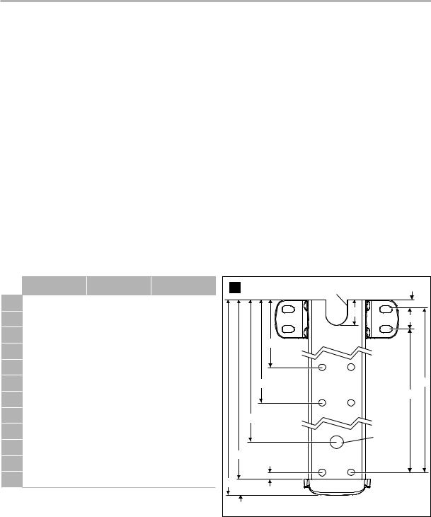
4.1 Hardware dimensions (back channel)
8962XX1.4X0#(L) 8962XX2.4X0#(L) 8962XX3.4X0#(L)
A |
62 |
3/4" |
66 1/4" |
66 1/4" |
B |
|
|
|
|
62 1/8" |
65 5/8 |
65 5/8" |
||
C |
|
|
|
|
60 1/8" |
63 5/8" |
63 5/8" |
||
D |
|
|
|
|
60 |
3/4" |
64 1/4" |
64 1/4" |
|
E |
|
|
|
|
61 |
1/2" |
65" |
65" |
|
F |
|
|
|
|
|
|
33" |
|
|
G |
|
|
|
|
|
|
39" |
|
|
H |
|
|
|
|
|
|
3/8" |
|
|
J |
|
|
|
|
|
|
1/4" |
|
|
K |
|
|
|
|
|
|
5/8" |
|
|
L |
|
|
|
|
|
|
3/4" |
|
|
M |
|
|
|
|
|
|
1 1/2" |
|
|
IIWiring harness location may be at the top or bottom of the back channel, depending on the awning model.
1 |
Top Wiring |
H |
|
Harness Notch |
|||
|
|||
|
|
M |
|
|
|
L |
|
|
F |
|
|
G |
|
E |
|
|
|
D |
|
C |
|
Bottom |
|
|
Wiring |
||
|
|
Harness |
|
|
|
Hole |
|
B |
J |
|
|
|
|
||
A |
|
|
|
K |
|
|
5 |
EN |
|
|

Power Awning
4.2 Door clearance
IIWhen the entry door is toward the center of the awning, add 2” to minimum distances.
Model |
Min. Distance (X) |
2 |
Awning Rail |
8962XX1.4X0#(L) |
12" |
|
|
8962XX2.4X0#(L) |
7" |
|
X |
|
|
||
8962XX3.4X0#(L) |
6" |
|
|
Doors, windows, lights, trim, slideout rooms, |
|
|
|
IIetc. must be considered when determining |
|
Entry Door |
|
the length and position of the awning to |
|
||
|
|
||
ensure that the awning will not obstruct them |
|
|
|
or be affected by them. |
|
|
|
5 PRE-INSTALLATION
5.1Installing the roller and edge guard (optional)
Do not allow the corner of the entry door to contact the awning fabric. Otherwise, premature wear or tearing of the awning fabric could occur. If there’s potential for a squared corner entry door to contact the awning fabric, a door roller kit (not included) must be installed. Failure to obey this notice could result in damage to the product or property.
3 |
|
4 |
Outer Entry Door
Door Edge Guard
1/4" – 3/8" (Above Door)
Inner Screen Door
EN |
6 |
|
|
 Loading...