

D-Link DGS-1250, DGS-1250-28X, DGS-1250-28XMP, DGS-1250-52X, DGS-1250-52XMP Hardware Installation Manual
DGS-1250 Series Gigabit Ethernet Smart Managed Switch Hardware Installation Guide
i

DGS-1250 Series Gigabit Ethernet Smart Managed Switch Hardware Installation Guide
Information in this document is subject to change without notice. Reproduction in any manner whatsoever, without the written
permission of D-Link Corporation, is strictly forbidden.
Trademarks used in this text: D-Link and the D-LINK logo are trademarks of D-Link Corporation; Microsoft and Windows are
registered trademarks of Microsoft Corporation.
Other trademarks and trade names may be used in this document to refer to either the entities claiming the marks and names or
their products. D-Link Corporation disclaims any proprietary interest in trademarks and trade names other than its own.
© 2019 D-Link Corporation. All rights reserved.
May, 2019 P/N 651GS1250015G
FCC Compliance Statement
This device complies with Part 15 of the FCC Rules. Operation is subject to the following two conditions: (1) This device may not
cause harmful interference, and (2) this device must accept any interference received, including interference that may cause
undesired operation.
D-Link Corporate
17595 Mt. Hermann Street
Fountain Valley, CA 92708
(800) 326-1688
CE Mark Warning
This equipment is compliant with Class A of CISPR 32. In a residential environment, this equipment may cause radio interference.
VCCI Warning
この装置は、クラス A 機器です。この装置を住宅環境で使用すると電波妨害を引き起こすことがあります。この場合には使用者が
適切な対策を講ずるよう要求されることがあります。 VCCI-A
BSMI Notice
此為甲類資訊技術設備,於居住環境中使用時,可能會造成射頻擾動,在此種情況下,使用者會被要求採取某些適當的對策。
Safety Compliance
Warning: Class 1 Laser Product: When using a fiber optic media expansion module, never look at the transmit laser while it is
powered on. Also, never look directly at the fiber TX port and fiber cable ends when they are powered on.
Avertissement : Produit Laser de Classe 1 : Ne regardez jamais le laser tant qu’il est sous tension. Ne regardez jamais
directement le port TX (Tramsmission) à fibres optiques et les embouts de câbles à fibres optiques tant qu’ils sont sous tension.
ii

DGS-1250 Series Gigabit Ethernet Smart Managed Switch Hardware Installation Guide
Table of Contents
Intended Readers ........................................................................................................................................................ v
Typographical Conventions ......................................................................................................................................... v
Notes and Cautions ..................................................................................................................................................... v
1. Introduction ............................................................................................................................................................... 6
Switch Description ....................................................................................................................................................... 6
Package Contents ........................................................................................................................................................ 6
Features ....................................................................................................................................................................... 6
Front Panel Components ............................................................................................................................................. 7
Ports ........................................................................................................................................................................ 8
Reset Button ........................................................................................................................................................... 9
LED Indicators ........................................................................................................................................................ 9
Rear Panel Components ............................................................................................................................................ 10
Side Panel Components ............................................................................................................................................ 11
Smart Fans ........................................................................................................................................................... 12
2. Installation ............................................................................................................................................................... 13
Installation Guidelines ................................................................................................................................................ 13
Installing the Switch without a Rack .......................................................................................................................... 13
Installing the Switch in a Standard 19" Rack ............................................................................................................. 14
Installing Transceivers into the Transceiver Ports ..................................................................................................... 15
Power On (AC Power) ............................................................................................................................................... 15
Power Failure (AC Power) .................................................................................................................................... 16
Installing Power Cord Retainer ............................................................................................................................. 16
3. Switch Connections ............................................................................................................................................... 19
Switch to an End Node .............................................................................................................................................. 19
Switch to Another Switch ........................................................................................................................................... 19
Switch to a Server ...................................................................................................................................................... 20
4. Switch Management ............................................................................................................................................... 21
Management Options ................................................................................................................................................. 21
Connecting to the Console Port ................................................................................................................................. 21
Connecting to the Switch for the First Time .......................................................................................................... 22
Creating a User Account ....................................................................................................................................... 23
Configuring the IP Address ................................................................................................................................... 23
Connecting using SNMP ............................................................................................................................................ 24
Traps ..................................................................................................................................................................... 24
Management Information Base (MIB) ................................................................................................................... 25
5. Web-based Switch Configuration ......................................................................................................................... 26
Introduction ................................................................................................................................................................ 26
Logging into the Web UI ............................................................................................................................................ 26
Web User Interface (Web UI) ..................................................................................................................................... 27
Areas of the Web UI ............................................................................................................................................. 28
Web Pages ........................................................................................................................................................... 28
Appendix A - Technical Specifications ....................................................................................................................... 30
General ...................................................................................................................................................................... 30
Physical and Environmental....................................................................................................................................... 30
Performance............................................................................................................................................................... 31
LED Indicators ........................................................................................................................................................... 32
Port Functions ............................................................................................................................................................ 33
Appendix B - Cables and Connectors ......................................................................................................................... 35
Ethernet Cable ........................................................................................................................................................... 35
iii

DGS-1250 Series Gigabit Ethernet Smart Managed Switch Hardware Installation Guide
Console Cable (RJ45 to RS-232) .............................................................................................................................. 36
Safety/Sécurité .............................................................................................................................................................. 37
Safety Instructions ..................................................................................................................................................... 37
Safety Cautions .................................................................................................................................................... 37
Consignes de sécurité ............................................................................................................................................... 38
Précautions de sécurité ........................................................................................................................................ 38
General Precautions for Rack-Mountable Prod uc ts .................................................................................................. 39
Protecting Against Electrostatic Discharge ................................................................................................................ 40
Warranty & Technical Support ....................................................................................................................................... 41
iv
DGS-1250 Series Gigabit Ethernet Smart Managed Switch Hardware Installation Guide
Intended Readers
The DGS-1250 Series Gigabit Ethernet Smart Managed Switch Hardware Installation Guide contains detailed
information about the hardware specifications of the switches in this series. It also contains brief information on how to
configure and manage a switch in this series. This manual is intended for advanced level users that are familiar with
network management concepts and terminology. For all practical reasons, all the switches in this series will simply be
referred to as the Switch throughout this manual.
Typographical Conventions
Convention Description
Boldface Font
Initial capital letter This convention is used to indicate a window name or keyboard key. For
Blue Courier Font
This convention is used to place emphasis on keywords. It also indicates a
button, toolbar icon, menu, menu item, system message, or a prompt
appearing on the screen. For example, click the Apply button.
example, press the Enter key.
This convention is used to represent a Command Line Interface (CLI)
example.
Notes and Cautions
NOTE: A note indicates important information that helps you make better use of your device.
CAUTION: A caution indicates a potential for property damage, personal injury, or death.
v

DGS-1250 Series Gigabit Ethernet Smart Managed Switch Hardware Installation Guide
1. Introduction
Switch Description
Package Contents
Features
Switch Description
The DGS-1250 Series is D-Link’s next generation Smart Managed Switch. The Switch has a combination of
10/100/1000 Mbps RJ45 ports and 1/10 Gbps SFP/SFP+ ports that may be used to connect various networking
devices to the Switch. The SFP/SFP+ ports are used with fiber-optical transceiver cabling in order to uplink various
other networking devices for a 1/10 Gbps link that may span great distances. The DGS-1250 Series also implements
D-Link’s innovative 3rd generation Green Ethernet technology (IEEE 802.3az) by not only saving power over inactive
links, but also turning off LEDs on a customized schedule and allowing ports to automatically enter the hiber nate d
state.
The D-Link DGS-1250 Series includes the following switches:
• DGS-1250-28X supports twenty-four RJ45 ports (10/100/1000 Mbps) and four SFP/SFP+ ports (1/10 Gbps).
• DGS-1250-28XMP supports twenty-four RJ45 PoE ports (10/100/1000 Mbps) and four SFP/SFP+ ports (1/10
Gbps).
• DGS-1250-52X supports forty-eight RJ45 ports (10/100/1000 Mbps) and four SFP/SFP+ ports (1/10 Gbps).
• DGS-1250-52XMP supports forty-eight RJ45 PoE ports (10/100/1000 Mbps) and four SFP/SFP+ ports (1/10
Gbps).
Package Contents
Open the shipping carton of the Switch and carefully unpack its contents. The carton should contain the following
items:
• One DGS-1250 Series switch.
• One Quick Installation Guide.
• One AC power cord.
• One console cable (RJ45 to RS-232).
• One rack mounting kit (two brackets and screws).
• Four rubber feet with adhesive backing.
• One power cord retainer set.
• One CD that includes a digital copy of the CLI Reference Guide, Web UI Reference Guide, and Hardware
Installation Guide.
If any item is missing or damaged, please contact your local D-Link reseller for replacement.
Features
The list of features below highlights the significant features of the Switch.
• Supports a 16K MAC address table (for DGS-1250-28X/28XMP); supports a 32K MAC address table (for DGS-
1250-52X/52XMP).
• Supports Flow Control (802.3x) in full-duplex compliant.
• Supports Jumbo Frames of up to 12288 bytes.
• Supports Spanning Tree with 802.1D 2004 STP/RSTP and 802.1Q 2005 MSTP.
• Supports Loopback Detection (LBD).
• Supports Link Aggregation (802.3ad and 802.3AX) with a maximum of 8 groups per Switch.
6

DGS-1250 Series Gigabit Ethernet Smart Managed Switch Hardware Installation Guide
• Supports Port Mirroring.
• Supports Layer 2 Multicast Filtering.
• Supports IGMP Snooping (v1, v2, v3 awareness) with up to 256 snoo pi ng groups and 128 st atic m ult icast
addresses. MLD Snooping (v1, v2 aware nes s ) with up to 256 snooping groups and 128 static multicast
addresses. IGMP Snooping and MLD Snooping share 128 static groups and 256 snoop ing grou ps .
• Supports Virtual LAN (802.1Q) with up to 4K static VLAN groups and 4K dynamic VLAN groups.
• Supports Port-based VLAN.
• Supports Asymmetric VLAN.
• Supports Auto Voice and Surveillance VLAN.
• Supports IP Interfaces with up to 4 IP interfaces.
• Supports Static Routing.
• Supports Quality of Service (QoS) with Queue Handling and Class of Service (CoS).
• Supports Access Control List (ACL) with Ingress ACL, Time-based ACL, and ACL Statistics.
• Supports Secure Shell (SSHv2) with IPv4/IP v6 acc es s .
• Support Transport Layer Security (TLS) vers io ns 1.0, 1.1, and 1.2.
• Supports Port Security of up to 64 MAC address es per port.
• Supports Broadcast and Multicast Storm Control.
• Supports Traffic Segmentation.
• Supports D-Link SafeGuard Engine.
• Supports ARP Spoofing Prevention.
• Supports IP-MAC-Port Binding (IMPB). This feature includes DHCP Snooping, IP Source Guard, Dynamic ARP
Inspection, DHCPv6 Guard, RA Guard, IPv6 Snooping, IPv6 Source Guard, IPv6 ND Snooping, and IPv6 ND
Inspection.
• Supports DoS Attack Prevention.
• Supports Port-based Network Access Control (PNAC) better known as 802.1X. This feature includes Local and
RADIUS database, and Port-based Access Control.
• Supports Guest VLAN.
• Supports Link Layer Discovery Protocol (LLD P) w ith LL DP-MED.
• Supports Accessibility using multiple interfaces like the Command Line Interface (CLI), Web-based Graphical
User Interface (Web-based GUI), and more.
• Supports Telnet Server and Client from IPv4 and IPv6.
• Supports Trivial File Transfer Protocol (TFTP) Client.
• Supports Simple Network Management Protocol (SNMP) version 1, 2c, and 3. Also supports SNMP Traps.
• Supports DHCP Client.
• Supports Dynamic Host Configuration Protocol (DHCP) Relay.
• Supports Traps and Logs.
• Support Dual Images and Conf igura tio ns .
• Supports Simple Network Time Protocol (SNTP).
• Support Power Saving using the Link Status Mode.
• Support Time-based Power-over-Ethernet (PoE).
• Supports IEEE 802.3az compliance.
• Supports D-Link Discovery Protocol (DDP).
• Supports MIBs like MIBII, Bridge MIB, SNMPv2 MIB, RMON MIB, RMONv2 MIB, Ether-like MIB, 802.3 MAU
MIB, 802.1p MIB, RADIUS Authentication Cl ient MIB, Ping MIB, L2 Sp ec if ic MIB, Pr ivate MIB, Ent it y MIB, an d
ZoneDefense MIB.
Front Panel Components
The front panel of the S witch features a variety of LED indicators, ports, a Reset button and a Mode button (only of
PoE supported switches).
7
DGS-1250 Series Gigabit Ethernet Smart Managed Switch Hardware Installation Guide
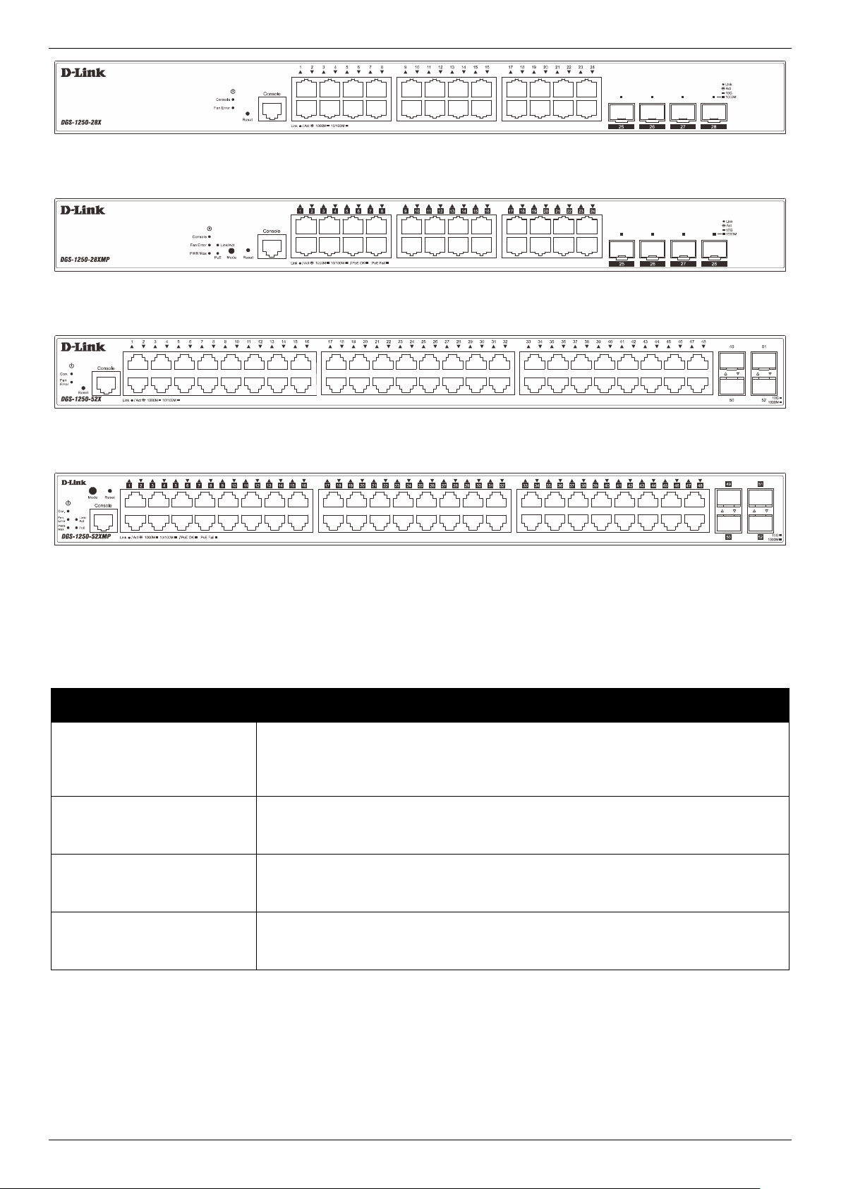
Figure 1-1 Front panel view of the DGS-1250-28X
Figure 1-2 Front panel view of the DGS-1250-28XMP
Figure 1-3 Front panel view of the DGS-1250-52X
Figure 1-4 Front panel view of the DGS-1250-52XMP
Ports
Ports that can be found on the front panel of this switch are listed in the table below.
Port Description
Console
10/100/1000 Mbps RJ45
Ports
The RJ45 console port can be used to connect to the Command Line Interface
(CLI) of the Switch for configuration, management, and monitoring. This port uses
a special console cable (included in this package) with a DB9 interface to connect
the Switch to the serial port (COM) of the PC.
The DGS-1250-28X and DGS-1250-52X Switches are equipped with 24 or 48 RJ45
Ethernet ports. These ports can operate at 10 Mbps, 100 Mbps, and 1 Gbps wirespeeds.
10/100/1000 Mbps RJ45 PoE
Ports
10 Gigabit SFP/SFP+ Ports
For a complete list of SFP/SFP+ transceivers that are compatible with this switch, refer to the SFP+/SFP Ports
section in Appendix A - Technical Specifications.
The DGS-1250-28XMP and DGS-1250-52XMP Switches are equipped with 24 or
48 RJ45 PoE Ethernet ports. These ports can operate at 10 Mbps, 100 Mbps, and
1 Gbps wire-speeds.
The Switch is equipped with 4 SFP/SFP+ ports. These ports can operate at 1
Gbps and 10 Gbps wire-speeds and support a wide collection of SFP/SFP+
transceivers.
8
DGS-1250 Series Gigabit Ethernet Smart Managed Switch Hardware Installation Guide
Reset Button
On the front panel of the Switch is a Reset button. The Switch will reboot or reset to factory default settings depending
on how long this button is pressed.
• Press and hold the Reset button for less than 5 seconds (release before 5 seconds) to reboot the Switch. All
unsaved configurations will be lost.
• Press and hold the Reset button for more than 5 seconds (release between 6 and 10 seconds) to reset the
software configuration of the Switch to the factory default settings. All the port LEDs will light up (solid amber)
for 2 seconds to indicate the start of the factory reset procedure.
LED Indicators
Located on the front panel of this switch are LED indicators: Power, Console, Fan Error, and Link/Act indicators for all
the ports. The DGS-1250-28XMP and DGS-1250-52XMP switches are equipped with Power Max., PoE indicators for
all the ports, and Link/Act and PoE indicators for mode selection.
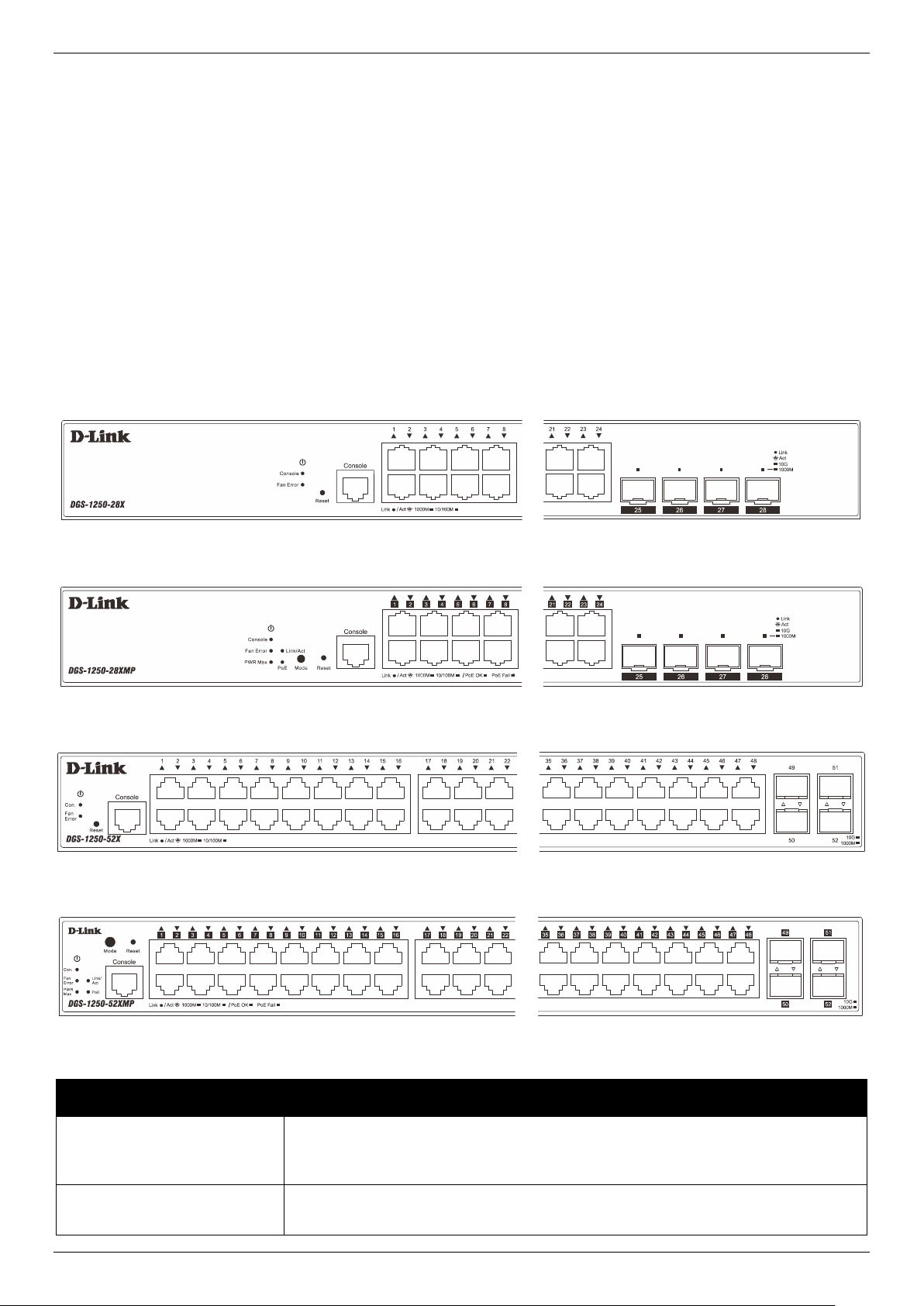
Figure 1-5 LED indicators for the DGS-1250-28X
Figure 1-6 LED indicators for the DGS-1250-28XMP
Figure 1-7 LED indicators for the DGS-1250-52X
Figure 1-8 LED indicators for the DGS-1250-52XMP
LED Description
Power
Console
This LED will light solid green after the Switch has been powered on successfully.
This LED will be off when the Switch is no longer receiving power (i.e. powered
off).
This LED will light solid green when the console port is active.
This LED will be off when the console port is not ac ti v e.
9
DGS-1250 Series Gigabit Ethernet Smart Managed Switch Hardware Installation Guide
LED Description
Fan Error
PWR Max.
(DGS-1250-28XMP and DGS-
1250-52XMP Only)
Link/Act LEDs
PoE
(DGS-1250-28XMP and DGS-
1250-52XMP Only)
This LED will light solid red when the fan fails.
This LED will be off when the fan is operating normally.
This LED will light solid red when the power supplied to attached PDs exceeds the
maximum PoE budget.
This LED will blink red when the power supplied to attached PDs approaches the
maximum PoE budget (within 7 Watts) and enters the Guardband mode.
This LED will be off when no power is supplied to attached PDs or when no PDs
are attached.
The Switch has LED indicators for Link and Activity.
RJ45 Ports: This LED will light solid green when there is a connection (or link) to
a 1000 Mbps Ethernet device or solid amber when there is a connection (or link)
to a 10/100 Mbps Ethernet device on any of the RJ45 ports. The LED will blink
green when a 1000 Mbps port is active or blink amber when a 10/100 Mbps port is
active. The LED will be off when there is no link or activity.
SFP/SFP+ Ports: This LED will li g ht solid green when there is a connection (or
link) to a 10 Gbps Ethernet device or solid amber when there is a connection (or
link) to a 1 Gbps Ethernet device at any at any of the SFP/SFP+ ports. The LED
will blink green when a 10 Gbps port is active or blink amber when a 1 Gbps port
is active. The LED will be off when there is no link or activity.
This LED will light solid green when the corresponding ports are feeding power to
the PoE devices plugged in.
This LED will light solid amber when the port is in an error condition state.
This LED will be off when the ports are not supplying power to the devices
plugged into the ports.
Please refer to the “LED Indicators” section in the Appendix A - Technical Specifications for more LED information.
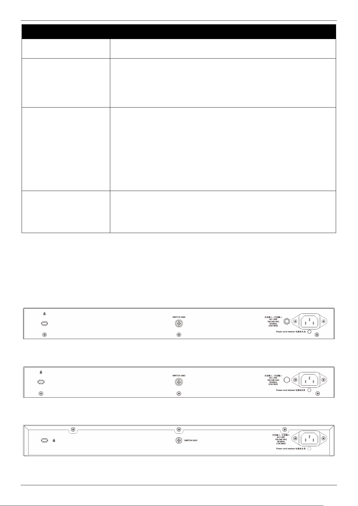
Rear Panel Components
The rear panel of this switch features a security lock, a GND, an AC po wer connector, and a power cord retainer hole.
Figure 1-9 Rear panel view of the DGS-1250-28X
Figure 1-10 Rear panel view of the DGS-1250-28XMP
Figure 1-11 Rear panel view of the DGS-1250-52X
10
DGS-1250 Series Gigabit Ethernet Smart Managed Switch Hardware Installation Guide
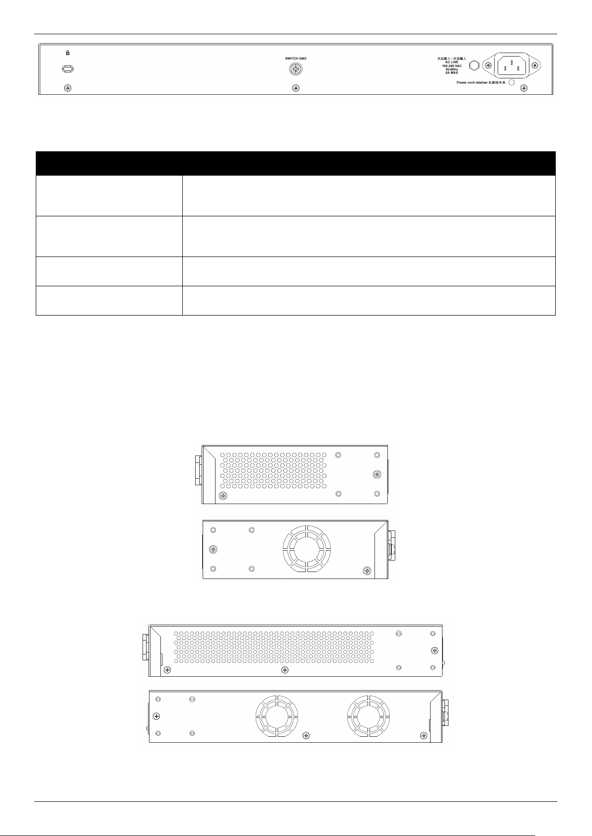
Figure 1-12 Rear panel view of the DGS-1250-52XMP
Components that can be found on the rear panel of this switch are listed in the table below.
Component Description
Security Lock
Switch GND
AC Power Connector
Power Cord Retainer Hole
Provide a Kensington-compatible security lock to be able to connect to a secure
immovable device. Insert the lock into the notch and turn the key to secure the
lock. The lock-and-cable apparatus should be purchased separately.
Use an electrical grounding wire and connect one end of the wire to the Switch
GND and the other end of the wire to an electrical grounding point most commonly
found on the Switch mounting rack itself.
The AC power cord with a three-pronged AC power connector can be plugged into
this receptacle to supply the Switch with 100-240 VAC power at 50-60 Hz.
The power cord retainer hole is used to insert the power cord retainer to secure
the AC power cord.
Side Panel Components
The side panels of this switch contain heat vents, fans, and rack-mounting screw holes. The heat vents are used to
dissipate internal heat and facilitate internal air circulation. Do not block these openings. Leave at least 4 inches of
space at the sides of the Switch for proper ventilation. Without proper heat dissipation and air circulation, system
components might overheat which could lead to system failure or even severely damaged components.
Figure 1-13 Side panels of the DGS-1250-28X
Figure 1-14 Side panels of the DGS-1250-28XMP
11
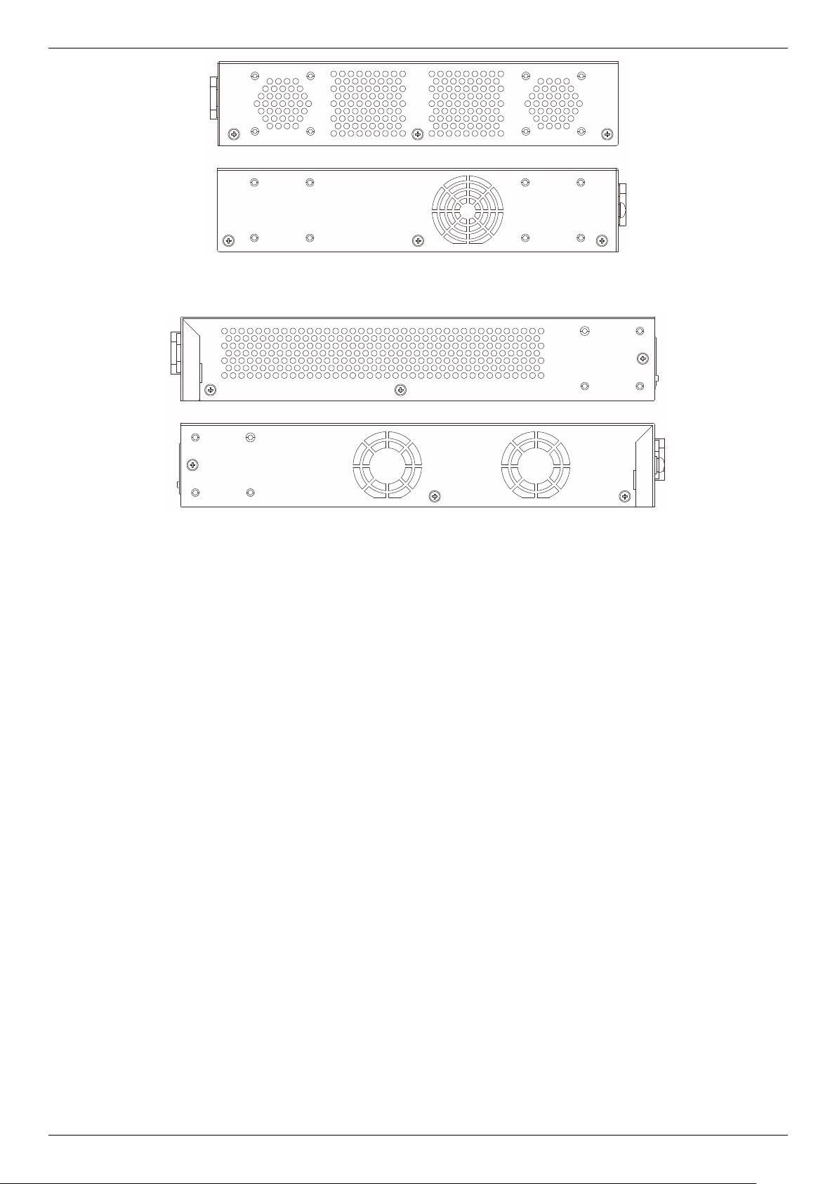
DGS-1250 Series Gigabit Ethernet Smart Managed Switch Hardware Installation Guide
Figure 1-15 Side panels of the DGS-1250-52X
Figure 1-16 Side panels of the DGS-1250-52XMP
Smart Fans
The DGS-1250 Series Switches includes smart fans that will automatically change their speed depending on the
internal temperature detected by the sensors built-in the Switch’s hardware.
The following will explain at what temperature the speed of the fan(s) will change:
• DGS-1250-28X: The fan speed will change from:
o Low Speed to High Speed at 69°C.
o High Speed to Low Speed at 57°C.
• DGS-1250-28XMP: The fan speed will change from:
o Low Speed to High Speed at 46°C.
o High Speed to Low Speed at 36°C.
• DGS-1250-52X: The fan speed will change from:
o Low Speed to High Speed at 65°C.
o High Speed to Low Speed at 60°C.
• DGS-1250-52XMP: The fan speed will change from:
o Low Speed to High Speed at 51°C.
o High Speed to Low Speed at 46°C.
12
DGS-1250 Series Gigabit Ethernet Smart Managed Switch Hardware Installation Guide
2. Installation
Installation Guidelines
Installing the Switch without a Rack
Installing the Switch in a Standard 19" Rack
Installing Transceivers into the Transceiver Ports
Power On (AC Pow e r)
Installation Guidelines
This section will discuss the hardware installation guidelines that the user must follow in order to properly and safely
install this switch into the appropriate environment.
• Visually inspect the power cord and see that it is fully secured to both the power connector, on t he S witc h, and
the electrical outlet that supplies power.
• Install the Switch in a fairly cool and dry place within the acceptable operating temperature and humidity
ranges. For more information about the acceptable operating temperature and humidity ranges, refer to the
Physical and Environmental section.
• Install the Switch in a site free from strong electromagnetic field generators such as motors, vibration, dust,
and direct exposure to sunlight.
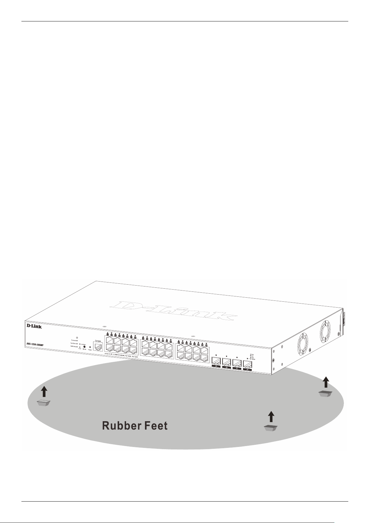
Installing the Switch without a Rack
This section is used to guide the user through installing the Switch in an area other than a switch rack. Attach the
included rubber feet to the bottom of the Switch. Take note that there should be marked blocks on the bottom of the
Switch to indicate where to attach the rubber feet. These markings are usually found in each corner on the bottom of
the device. The rubber feet cushion the Switc h, protecting the casing from scratches and preventing it from scratching
other surfaces.
Figure 2-1 Attaching rubber feet to the Switch
Install the Switch on a sturdy, level surface that can support the weight of the Switch (see the Weight section in
Appendix A - Technical Specifications.). Do not place any heavy objects on the Switch. The power outlet should be
13
DGS-1250 Series Gigabit Ethernet Smart Managed Switch Hardware Installation Guide
within 1.82 meters (6 feet) of the Switch. Make sure that there is proper heat dissipation from and adequate ventilation
around the Switch. Leave at least 10 cm (4 inches) of space at the front, sides, and rear of the Switch for ventilation.
Installing the Switch in a Standard 19" Rack
This section is used to guide the user through installing the Switch into a switch rack. The Switch can be mounted in a
standard 19"(1U) rack using the provided mounting brackets.
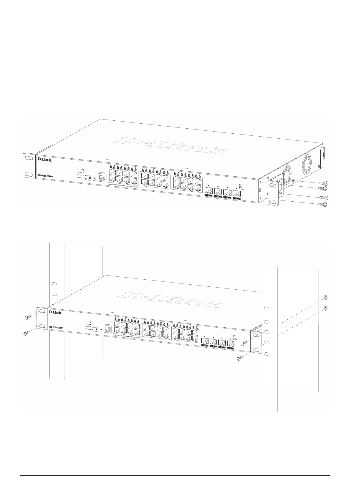
1. Fasten the mounting brackets to the sides of the Sw itch using the screws provided.
Figure 2-2 Attaching rack-mount brackets to the Switch
2. Fasten the mounting brackets in any available open space in the rack using the screws provided.
Figure 2-3 Installing the Switch in a Rack
Make sure that there is adequate space around the Switch to allow for proper air flow, ventilation, and cooling.
14
DGS-1250 Series Gigabit Ethernet Smart Managed Switch Hardware Installation Guide
Installing Transceivers into the Transceiver Ports
The Switch is equipped with Small Form-factor Pluggable (SFP) and Enhanced Small Form-factor Pluggable (SFP+)
ports that can be used to connect various other networking devices to this switch that do not support the standard
RJ45 wiring connection. These ports are generally used to connect this switch to optical fiber connections and can be
used to connect devices to the Switch over great distances. The maximum distance that the RJ45 wiring connection
can reach is 100 meters. Fiber optic connections can span several kilometers.
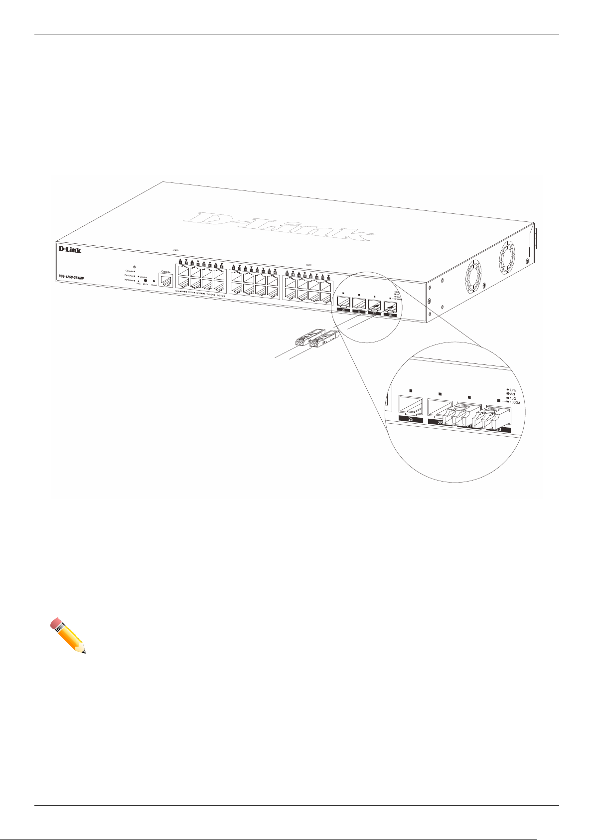
The figure below illustrates how to properly insert SFP/SFP+ transceivers into th e S witch’s SFP/SFP+ ports.
Figure 2-4 Inserting transceivers into the transceiver ports
The SFP/SFP+ ports also support other transceiver form factors like SFP and SFP+ transceivers. A complete list of
SFP/SFP+ transceivers, compatible with this switch, can be found in the SFP+/SFP Ports section in Appendix A -
Technical Specifications at the end of this document.
NOTE: Only use pluggab le optica l m odules and D irec t-Attach Cables (DAC) that meet the following
regulatory requirements:
• Class 1 Laser Product
• UL and/or CSA registered component for North America
• FCC 21 CFR Chapter 1, Sub-chapter J in accordance with FDA & CDRH requirements
• IEC/EN 60825-1/-2: 2007 2nd edition or later, European Standard
Power On (AC Power)
Plug one end of the AC power cord into the power socket of the Switch and the other end into the local power source
outlet. After the system is powered on, the LED will blink green to indicate that the system is booting up.
15
DGS-1250 Series Gigabit Ethernet Smart Managed Switch Hardware Installation Guide
Power Failure (AC Power)
In the event of a power failure, just as a precaution, unplug the power cord from the Switch. Afterthe power returns,
plug the power cord back into the power socket of the Switch.
Installing Power Cord Retainer
To prevent accidental removal of the AC power cord, it is recommended to install the power cord retainer together with
the power cord.
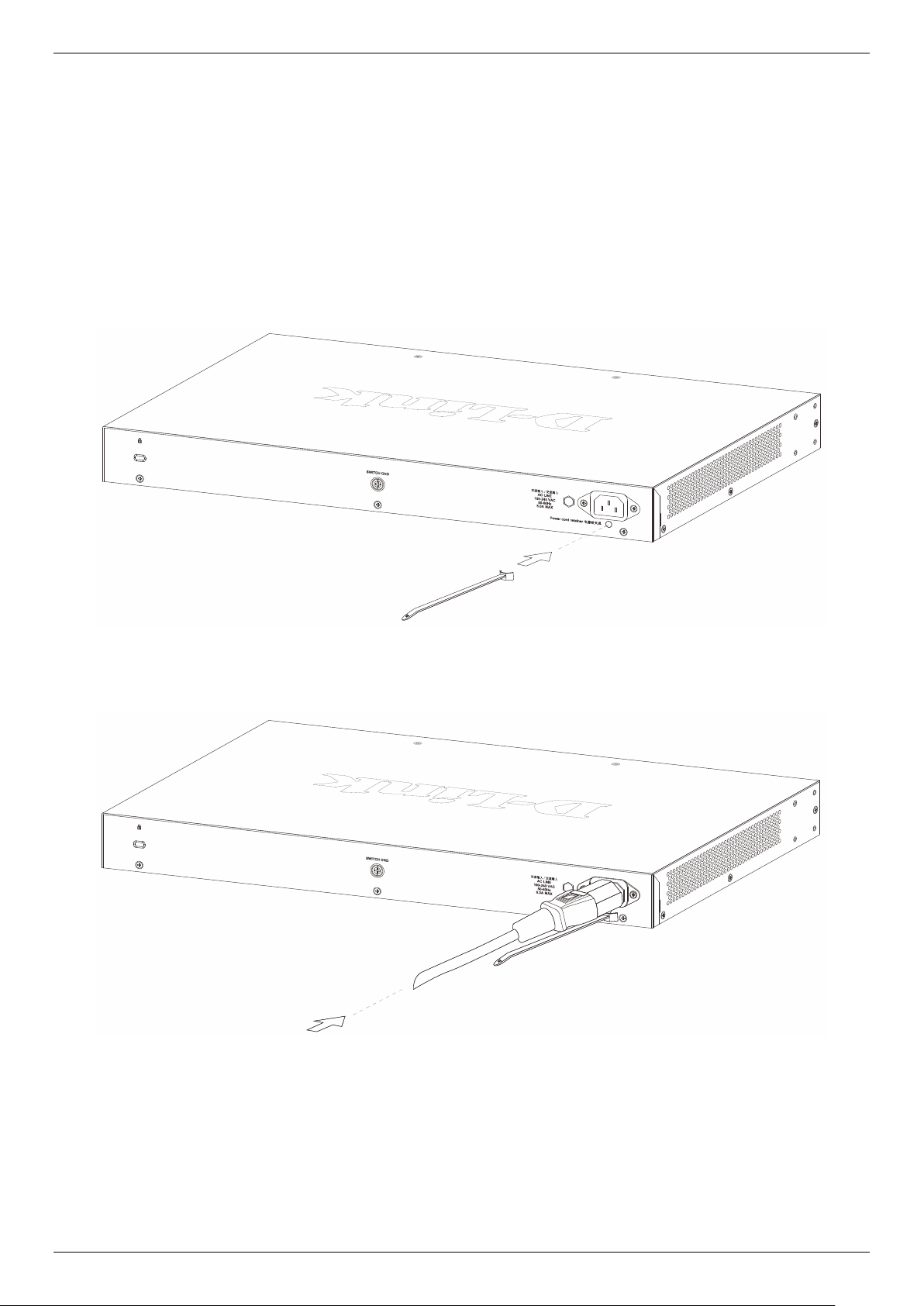
1. With the rough side facing down, insert the tie wrap into the hole below the power socket.
Figure 2-5 Insert Tie Wrap into the Switch
2. Plug the AC power cord into the power socket of the Switch.
Figure 2-6 Connect the power cord to the Switch
16
DGS-1250 Series Gigabit Ethernet Smart Managed Switch Hardware Installation Guide
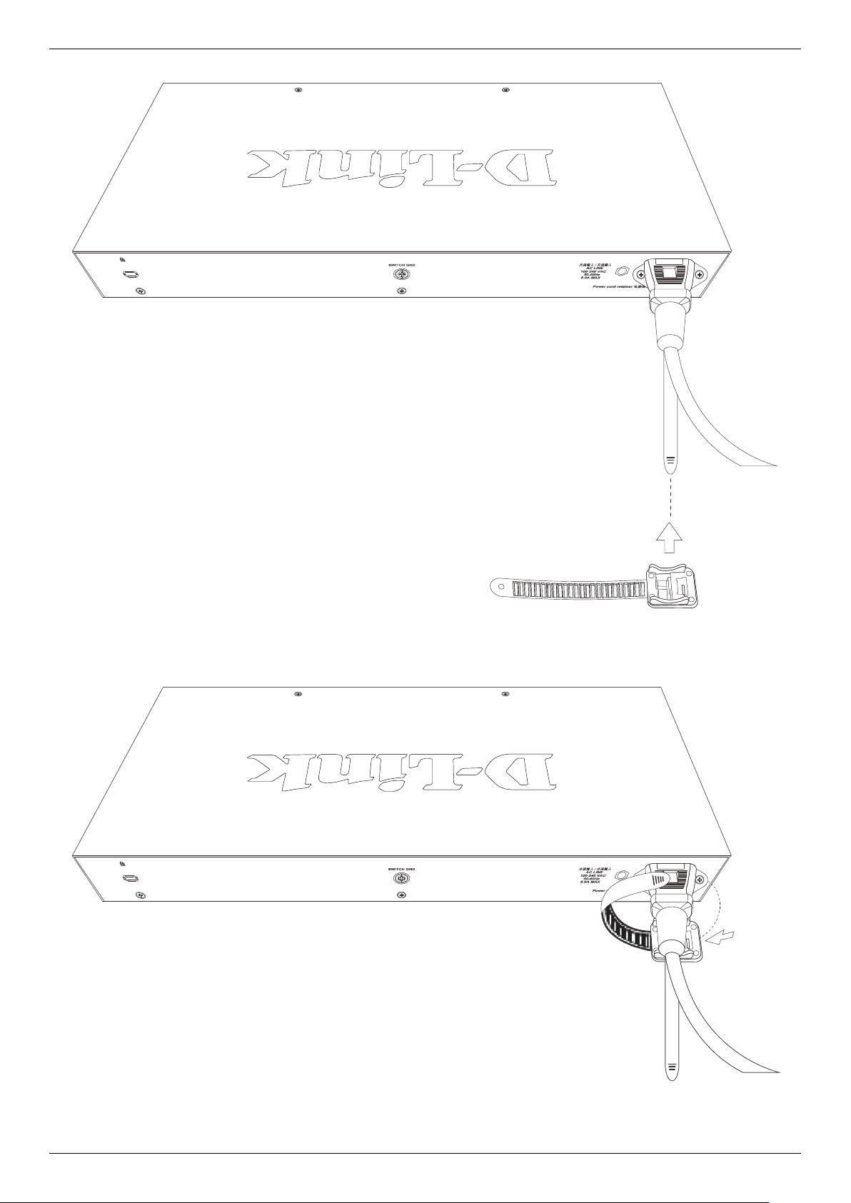
3. Slide the retainer through the tie wrap until the end of the cord.
Figure 2-7 Slide the Retainer through the Tie Wrap
4. Circle the tie of the retainer around the power cord and into the locker of the retainer.
Figure 2-8 Circle around the power cord
17
 Loading...