

Page 1
User Manual
DGS-1210/ME
Metro Ethernet Switch Series
Ver.1.01
Page 2

Page 3

Table of Contents DGS-1210 series Metro Ethernet Managed Switch User Manual
Table of Contents
Table of Contents ............................................................................................................................................. i
About This Guide ............................................................................................................................................. 1
Terms/Usage .................................................................................................................................................. 1
Copyright and Trademarks ............................................................................................................................ 1
1 Product Introduction ................................................................................................................................... 2
Switch Description .......................................................................................................................................... 2
Front Panel Description.................................................................................................................................. 2
LED Indicators ................................................................................................................................................ 6
Rear Panel Description .................................................................................................................................. 7
Side Panel Description ................................................................................................................................... 9
Gigabit Fiber Ports ......................................................................................................................................... 9
Connecting the DPS-200A/500A to the RPS Port (for DGS-1210-10/12TS/28X/28XS/ME only) ............... 10
Installing the RPS into a Rack-mount Chassis (for DGS-1210-10/12TS/2 8X/28X S / ME only) .................... 11
DPS-800 Rack-mount Chassis ................................................................................................................. 11
2 Hardware Installation ................................................................................................................................ 12
Step 1: Unpacking ........................................................................................................................................ 12
Step 2: Switch Installation ............................................................................................................................ 12
Desktop or Shelf Installation ..................................................................................................................... 12
Rack Installation ....................................................................................................................................... 12
Step 3 – Plugging in the AC Power Cord ..................................................................................................... 13
Power Failure ........................................................................................................................................... 14
3 Getting Started ........................................................................................................................................... 15
Management Options ................................................................................................................................... 15
Using Web-based Management .................................................................................................................. 15
Supported Web Browsers ........................................................................................................................ 15
Connecting to the Switch .......................................................................................................................... 15
Login Web-based Management ............................................................................................................... 16
Web-based Management ............................................................................................................................. 16
4 Configuration ............................................................................................................................................. 17
Web-based Management ............................................................................................................................. 17
Tool Bar > Save Menu ................................................................................................................................. 18
Save Configuration ................................................................................................................................... 18
Save Log .................................................................................................................................................. 18
Tool Bar > Tool Menu .................................................................................................................................. 18
Reset System ........................................................................................................................................... 18
Reboot Device .......................................................................................................................................... 19
Configuration Backup & Restore .............................................................................................................. 19
Firmware Backup & Upgrade ................................................................................................................... 19
Flash Information ...................................................................................................................................... 20
Tool Bar > Online Help ................................................................................................................................. 20
Function Tree ............................................................................................................................................... 21
Device Information.................................................................................................................................... 21
System > System Settings ....................................................................................................................... 22
System > Firmware Information ............................................................................................................... 23
System > Serial Port Settings................................................................................................................... 23
System > IP Interface ............................................................................................................................... 24
System > IPv6 System Settings ............................................................................................................... 24
ii
Page 4

Table of Contents DGS-1210 series Metro Ethernet Managed Switc h User Manual
System > IPv6 Route Settings.................................................................................................................. 25
System > IPv6 Neighbor Settings ............................................................................................................ 26
System > DHCP Auto Configuration ........................................................................................................ 26
System > DHCP Auto Image .................................................................................................................... 26
System > Port Configuration > Port Settings ........................................................................................... 27
System > Port Configuration > Port Description ...................................................................................... 27
System > Port Configuration > Port Error Disabled ................................................................................. 28
System > Port Configuration > Port Media Type ...................................................................................... 28
System > SNMP Settings > SNMP Global State ..................................................................................... 28
System > SNMP Settings > SNMP User Table ........................................................................................ 29
System > SNMP Settings > SNMP Group Table ..................................................................................... 29
System > SNMP Settings > SNMP View Table ....................................................................................... 30
System > SNMP Settings > SNMP Community Table ............................................................................. 30
System > SNMP Settings > SNMP Host Table ........................................................................................ 31
System > SNMP Settings > SNMP Engine ID ......................................................................................... 31
System > SNMP Settings > SNMP Trap Settings .................................................................................... 31
System > User Accounts .......................................................................................................................... 32
System > MAC Address Aging Time ........................................................................................................ 32
System > ARP Aging Time Settings ......................................................................................................... 33
System > PPPoE Circuit ID Insertion Settings ......................................................................................... 33
System > Web Settings ............................................................................................................................ 34
System > Telnet Settings ......................................................................................................................... 34
System > Password Encryption................................................................................................................ 34
System > Ping Test .................................................................................................................................. 34
System > MAC Notification Settings ........................................................................................................ 35
System > System Log Configuration > System Log Settings .................................................................. 35
System > System Log Configuration > System Log Server ..................................................................... 36
System > Time Profile .............................................................................................................................. 36
System > Power Saving ........................................................................................................................... 37
System > IEEE802.3az EEE Settings ...................................................................................................... 37
System > SMTP Service > SMTP Server Settings .................................................................................. 38
System > SMTP Service > SMTP Service ............................................................................................... 38
System > D-Link Discover Protocol Settings ............................................................................................ 39
Configuration > Jumbo Frame .................................................................................................................. 40
Configuration > 802.1Q VLAN .................................................................................................................. 40
Configuration > VLAN Status ................................................................................................................... 42
Configuration > MAC-Based VLAN Settings ............................................................................................ 42
Configuration > GVRP Settings ................................................................................................................ 43
Configuration > GVRP Timer Settings ..................................................................................................... 43
Configuration > QinQ > QinQ Settings ..................................................................................................... 44
Configuration > QinQ > VLAN Translati on CVID Entry Settings .............................................................. 45
Configuration > 802.1v Protoc ol VL AN > 802.1 v Protocol Group Settings .............................................. 45
Configuration > 802.1v Protoc ol VL AN > 802.1 v Protocol VLAN Settings............................................... 46
Configuration > VLAN Trunk Settings ...................................................................................................... 46
Configuration > Link Aggregation > Port Trunkings ................................................................................. 47
Configuration > Link Aggregation > LACP Port Settings.......................................................................... 47
Configuration > BPDU Protection Settings ............................................................................................... 48
Configuration > IGMP Snooping > IGMP Snooping ................................................................................. 49
Configuration > IGMP Snooping > IGMP Access Control Settings .......................................................... 51
iiii
Page 5

Table of Contents DGS-1210 series Metro Ethernet Managed Switch User Manual
Configuration > IGMP Snooping > ISM VLAN Settings ........................................................................... 52
Configuration > IGMP Snooping > Host Table ......................................................................................... 53
Configuration > IGMP Snooping > IP Multicast Profile Settings .............................................................. 53
Configuration > IGMP Snooping > Limited Multicast Range Settings ...................................................... 53
Configuration > IGMP Snooping > Max Multicast Group Settings ........................................................... 54
Configuration > MLD Snooping > MLD Snooping Settings ...................................................................... 54
Configuration > MLD Snooping > MLD Host Table .................................................................................. 55
Configuration > Port Mirroring .................................................................................................................. 55
Configuration > Loopback Detection ........................................................................................................ 56
Configuration > SNTP Settings > Time Settings ...................................................................................... 57
Configuration > SNTP Settings > TimeZone Settings .............................................................................. 57
Configuration > DHCP/BOOTP Relay > DHCP/BOOTP Relay Global Settings ...................................... 58
Configuration > DHCP/BOOTP Relay > DHCP/BOOTP Relay Interface Settings .................................. 60
Configuration > DHCP Local Relay Settings ............................................................................................ 60
Configuration > DHCPv6 Relay Settings .................................................................................................. 61
Configuration > Spanning Tree > STP Bridge Global Settings ................................................................ 62
Configuration > Spanning Tree > STP Port Settings ............................................................................... 63
Configuration > Spanning Tree > MST Configuration Identification ......................................................... 64
Configuration > Spanning Tree > STP Instance Settings ........................................................................ 65
Configuration > Spanning Tree > MSTP Port Information ....................................................................... 66
Configuration > Ethernet OAM > Ether net O AM Port S etti ngs ................................................................ 66
Configuration > Ethernet OAM > Ether net O AM Event C onf igura tio n ..................................................... 67
Configuration > DDM > DDM Settings ..................................................................................................... 67
Configuration > DDM > DDM Temperature Threshold Settings .............................................................. 68
Configuration > DDM > DDM Voltage Settings Threshold Settin gs ......................................................... 69
Configuration > DDM > DDM Bias Current Threshold Settings ............................................................... 69
Configuration > DDM > DDM TX Power Threshold Settings ................................................................... 70
Configuration > DDM > DDM RX Power Threshold Settings ................................................................... 70
Configuration > DDM > DDM Status Table .............................................................................................. 71
Configuration > DULD > DULD Global Settings ....................................................................................... 71
Configuration > DULD > DULD Port Settings .......................................................................................... 72
Configuration > Multicast Forwarding & Filtering > Multicast Forwarding ................................................ 72
Configuration > Multicast Forwarding & Filtering > Multicast Filtering ..................................................... 73
QoS > Traffic Control ................................................................................................................................ 73
QoS > Bandwidth Control ......................................................................................................................... 74
QoS > CoS Scheduling Mechanism ......................................................................................................... 75
QoS > CoS Output Scheduling ................................................................................................................ 75
QoS > 802.1p Default Priority................................................................................................................... 76
QoS > 802.1p User Priority ...................................................................................................................... 76
QoS > DSCP Priority Settings .................................................................................................................. 76
QoS > Priority Settings ............................................................................................................................. 77
RMON > RMON Basic Settings................................................................................................................ 77
RMON > RMON Ethernet Statistics Configuration ................................................................................... 78
RMON > RMON History Control Configuration ........................................................................................ 78
RMON > RMON Alarm Configuration ...................................................................................................... 78
RMON > RMON Event Configuration ....................................................................................................... 79
Security > Trusted Host ............................................................................................................................ 80
Security > Safeguard Engine.................................................................................................................... 80
Security > CPU Protect ............................................................................................................................ 80
iii
Page 6

Table of Contents DGS-1210 series Metro Ethernet Managed Switc h User Manual
Security > ARP Spoofing Prevention ....................................................................................................... 81
Security > Gratuitous ARP ....................................................................................................................... 81
Security > Port Security ............................................................................................................................ 82
Security > SSL Settings ............................................................................................................................ 83
Security > Smart Binding > Smart Binding Settings ................................................................................. 84
Security > Smart Binding > Smart Binding ............................................................................................... 84
Security > Smart Binding > White List ...................................................................................................... 85
Security > Smart Binding > Black List ...................................................................................................... 85
Security > Smart Binding > DHCP Snooping List .................................................................................... 86
Security > 802.1X > 802.1X Settings ....................................................................................................... 86
Security > 802.1X > 802.1X User ............................................................................................................. 88
Security > 802.1X > 802.1X Authentication RADIUS ............................................................................... 88
Security > 802.1X > 802.1X Guest VLAN ................................................................................................ 89
Security > MAC Address Table > Static MAC .......................................................................................... 89
Security > MAC Address Table > Dynamic Forwarding Table ................................................................. 90
Security > MAC Address Table > Auto Learning Vlan Settings ............................................................... 90
Security > Access Authentic ation Contr ol > Authentication Policy Settings ............................................ 91
Security > Access Authentication Control > Application Authentication Settings .................................... 91
Security > Access Authentication Control > Authentication Server Group .............................................. 92
Security > Access Authentic ation Contr ol > Authentication Server ......................................................... 93
Security > Access Authentic ation Contr ol > Login Met hod Lists .............................................................. 93
Security > Access Authentic ation Contr ol > Enabl e Me thod Lis ts ........................................................... 94
Security > Access Authentic ation Contr ol > Local Ena ble Password Settings ........................................ 95
Security > Traffic Segmentation ............................................................................................................... 95
Security > DoS Prevention Settings ......................................................................................................... 95
Security > DHCP Server Screening > DHCP Server Screening Port Settings ........................................ 96
Security > DHCP Server Screeni ng > DHCP Server Screening Vlan Settings........................................ 97
Security > DHCP Server Screening > Filter DH CP Serv er ...................................................................... 97
Security > SSH Settings > SSH Settings ................................................................................................. 97
Security > SSH Settings > SSH Authmode and Algorithm Settings ........................................................ 98
Security > SSH Settings > SSH User Authentication Lists ...................................................................... 99
Security > MAC-based Access Control (MAC) > MAC-based Access Control Settings ........................ 100
Security > MAC-based Access Control (MAC) > MAC-based Access Control Local Settings .............. 101
Security > MAC-based Access Control (MAC) > MAC-based Access Control Authentication State .... 101
Security > Web-based Access Control (WAC) > WAC Global Settings ................................................. 102
Security > Web-based Access Control (WAC) > WAC User Settings ................................................... 103
Security > Web-based Access Control (WAC) > WAC Port Settings .................................................... 103
Security > Web-based Access Control (WAC) > WAC Authentication State ......................................... 103
Monitoring > Statistics ............................................................................................................................ 104
Monitoring > Session Table .................................................................................................................... 105
Monitoring > CPU Utilization .................................................................................................................. 105
Monitoring > Memory Utilizatio n ............................................................................................................. 105
Monitoring > Port Utilization ................................................................................................................... 106
Monitoring > Packet Size ........................................................................................................................ 107
Monitoring > Packets > Transmitted (TX) .............................................................................................. 108
Monitoring > Packets > Received (RX) .................................................................................................. 109
Monitoring > Packets > UMB Cast (RX) ................................................................................................. 111
Monitoring > Errors > Received (RX) ..................................................................................................... 112
Monitoring > Errors > Transmitted (TX).................................................................................................. 113
iivv
Page 7

Table of Contents DGS-1210 series Metro Ethernet Managed Switch User Manual
Monitoring > Cable Diagnostics ............................................................................................................. 115
Monitoring > System Log ........................................................................................................................ 116
Monitoring > Browse ARP Table ............................................................................................................ 116
Monitoring > Ethernet OAM > Browse Ether net O AM E vent Lo g .......................................................... 116
Monitoring > Ethernet OAM > Browse Ether net O AM S tatist ic s ............................................................ 117
Monitoring > IGMP Snooping > IGMP Snooping Group ........................................................................ 117
Monitoring > IGMP Snooping > IGMP Snooping Host ........................................................................... 118
Monitoring > Port Access Control > RADIU S Authentication ................................................................. 118
Monitoring > Port Access Control > RADIU S Acc oun t Cli ent ................................................................ 119
ACL > ACL Configuration W izard ........................................................................................................... 120
ACL > Access Profile Lis t ....................................................................................................................... 121
ACL > ACL Finder .................................................................................................................................. 122
ACL > CPU Filter Configuration Wizard ................................................................................................. 123
ACL > CPU Filter Access Profile List ..................................................................................................... 124
ACL > CPU Filter Finder ......................................................................................................................... 125
ACL > ACL Flow Meter ........................................................................................................................... 125
PoE > PoE Port Settings (DGS-1210-10P/28P/52P/52MP/ME onl y) ..................................................... 126
PoE > PoE System Settings (DGS-1210-10P/28P/52P/52M P/M E only) ............................................... 128
Time-Based PoE > Time Range Settings .............................................................................................. 128
LLDP > LLDP Global Settings ................................................................................................................ 129
LLDP > Basic LLDP Port S etti ngs .......................................................................................................... 129
LLDP > 802.1 Extension LLDP Port Settings ......................................................................................... 130
LLDP > 802.3 Extension LLDP Port Settings ......................................................................................... 131
LLDP > LLDP Management Address Settings ....................................................................................... 131
LLDP > LLDP Statistics Table ................................................................................................................ 132
LLDP > LLDP Management Address Table ........................................................................................... 133
LLDP > LLDP Local Port Table .............................................................................................................. 133
LLDP > LLDP Remote Port Table .......................................................................................................... 134
LLDP > LLDP-MED Settings .................................................................................................................. 136
Appendix A - Ethernet Technology ............................................................................................................ 137
Gigabit Ethernet Technology ..................................................................................................................... 137
Fast Ethernet Technology .......................................................................................................................... 137
Switching Technology ................................................................................................................................ 137
Appendix B - Ethernet Technology ............................................................................................................ 138
Features ..................................................................................................................................................... 138
L2 Features ............................................................................................................................................ 138
VLAN ...................................................................................................................................................... 138
L3 Features ............................................................................................................................................ 138
QoS (Quality of Service) ......................................................................................................................... 138
Security ................................................................................................................................................... 138
OAM ....................................................................................................................................................... 139
Management ........................................................................................................................................... 139
v
Page 8

Page 9
About This Guide DGS-1210 series Metro Ethernet Managed Switch User Manual
he model you have purchased may
detailed information about your switch, its
information that
About This Guide
This guide provides instructions to inst all the D-Link DGS-1210/ME Metro Ethernet Switch and to configure
with HTTP step-by-step.
Note: T
appear slightly different from the illustrations
shown in the document. Refer to the Product
Instruction and Technical Specification sections
for
components, network connections, and technica l
specifications.
This guide is mainly divided into three parts:
1. Hardware Installation: Ste p -by-step hardware installation procedures.
2. Getting Started: A startup guide for basic switch installation and settings.
3. Configuration: Information about the function descriptions and configuration settings.
Terms/Usage
In this guide, the term “Switch” (first letter capitalized) refers to DGS-1210/ME Metro Ether net Switch, and
“switch” (first letter lo wer case) ref ers to other Ethern et switches. Some technologi es refer to term s “switch”,
“bridge” and “switching hubs” interchangeably, and both are commonly accepted for Ethernet switches.
A NOTE indicates important
helps a better use of the device.
A CAUTION indicates pote ntial prop erty dam age
or personal injury.
Copyright and Trademarks
Information in this document is subjected to change without notice.
© 2014 D-Link Corporation. All rights reserved.
Reproduction in any manner whatsoever without the written permission of D-Link Corporation is strictly
forbidden.
Trademarks used in th is text: D-Link and the D-LIN K logo are trademarks of D-Link Corporation; Micros oft
and Windows are registered trademarks of Microsoft Corporation.
Other trademarks and trade names ma y be used in this document to refer to either the entities cla iming the
marks and names or their products. D-Link Corporation discl aims an y proprietary interest i n trademark s and
trade names other than its own.
1
Page 10
1 Product Introduction DGS-1210 series Metro Ethernet Managed Switch User Manual
1 Product Introduction
Switch Description
Front Panel Description
LED Indicators
Rear Panel Description
Side Panel Description
Connecting the DPS-200A/500A to the RPS Port (for DGS-1210-10/ME only)
Installing the RPS into the Rack-mount Chassis (for DGS-1210-10/12TS/28X/28XS/ME only)
Switch Description
The DGS-1210/ME Metro Ethernet Switch is equipped with Copper ports (10/100/1000Mbps) and SFP
ports (1000Mbps) that can be used to attach various networking devices to the network like Com puters,
Notebooks, Print Servers, Network Attached Storage devices, IP Cam eras, VoIP PBX devices, and other
Switches. The Sm all Form Factor Por ta ble ( SFP) port s c an be us ed t oget her with f iber -opt ica l trans c ei vers in
order to connect various other n etworking devices , using a fiber-op tic connection , to the network at Gigabit
Ethernet speeds over great distances.
This DGS-1210/ME Metro Ethernet Switch provides unsurpassed performance, fault tolerance, scalability,
robust security, standar d-based interoperab ility and impressive techn ology to future-proof depar tmental and
enterprise network deployments.
It allows IGMP Snooping a nd Authentication, QoS, B andwidth Control, ACL and many security functions. It
can be managed by Web UI, or commands via Telnet.
The DGS-1210/ME Metro Ether net Switches have different port configuration (10/100/1000Base-T or SFP
ports) that ma y be used in to uplink var ious network devices to the Switch, inc luding PCs, hubs and other
switches to provide a gigabit Ethernet uplink in full-duplex mode. The SFP (Small Form Factor Portable)
ports are used with fiber-o ptical transceiver c abling in order to up link various other net working devices for a
gigabit link that may span great distances.
Front Panel Description
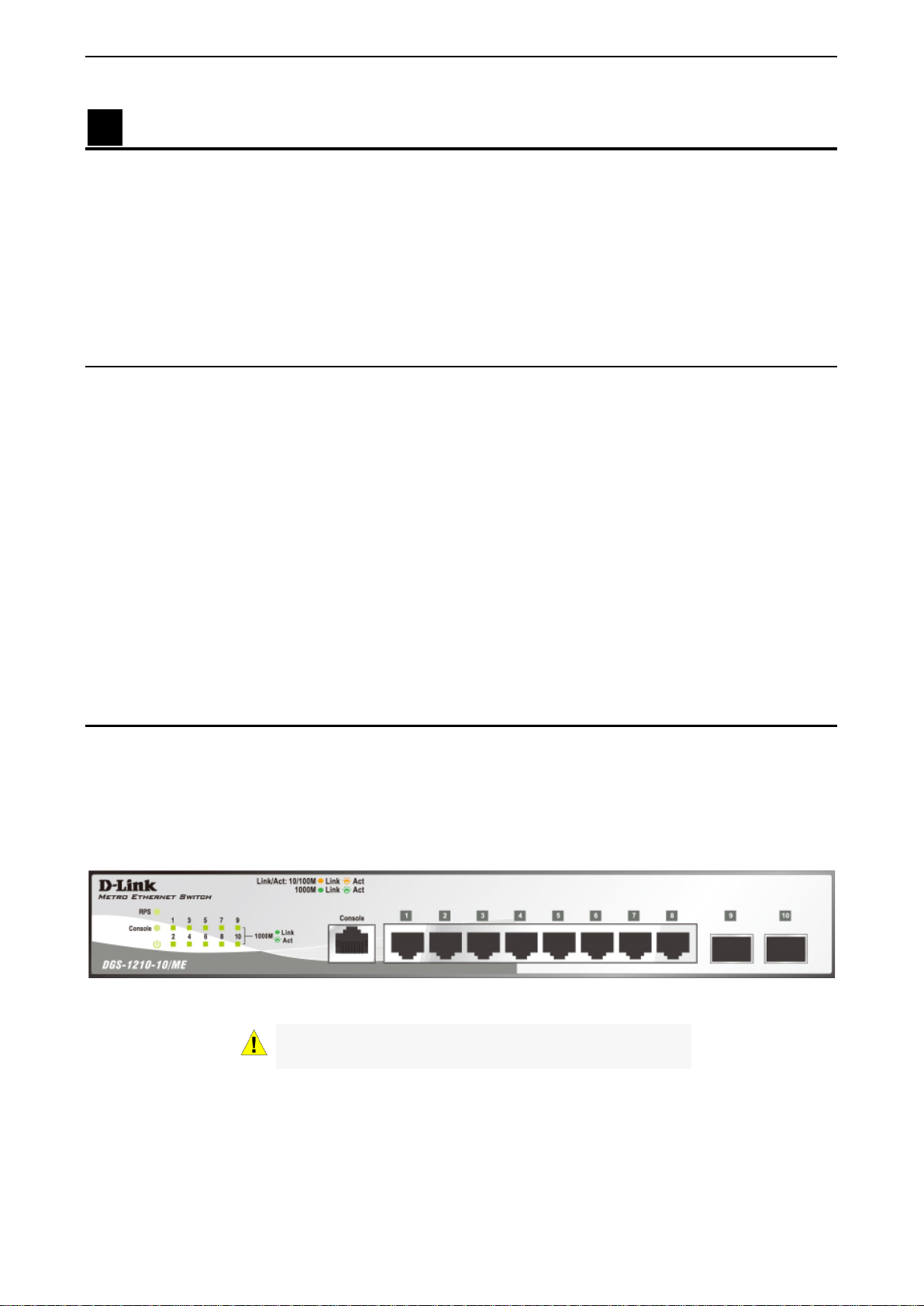
The front panel of the DGS-1210-10/ME switch consists out of the following:
• 8 10/100/1000Mbps Copper Ports
• 2 1000Mbps SFP ports
• One RJ-45 Console Port
• LEDs for Power, Console, RPS, Link/Act for port 1 ~ 10.
Figure 1.1 – DGS-1210-10/ME Fron t Panel
CAUTION: The MiniGBIC ports should use UL listed
Optical Transceiver product, Rated Laser Class I. 3.3Vdc.
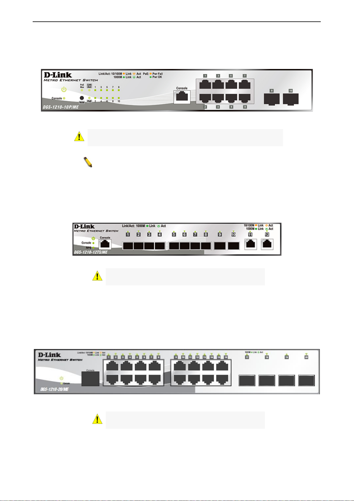
The front panel of the DGS-1210-10P/ME switch consists out of the following:
• 8 10/100/1000Mbps Copper Ports
• 2 1000Mbps SFP ports
• One RJ-45 Console Port
2
Page 11
1 Product Introduction DGS-1210 series Metro Ethernet Managed Switch User Manual
listed Optical
NOTE: The power budget is 78 Watts for DGS-1210-10P/ME.
• LEDs for Power, PoE Max, Console, RPS, Link/Act for port 1 ~ 10.
• Mode: By pressing the Mode button, the Port LED will switch between Link/Act and PoE modes.
Figure 1.2 – DGS-1210-10P/ME Front Panel
CAUTION: The MiniGBIC ports should use UL
Transceiver product, Rated Laser Class I. 3.3Vdc.
The front panel of the DGS-1210-12TS/ME switch consists out of the following:
• 10 1000Mbps SFP port
• 2 10/100/1000Mbps Copper Ports
• One RJ-45 Console Port
• LEDs for Power, Console, RPS, Link/Act for port 1 to 12
Figure 1.3 – DGS-1210-12TS/ME Front Panel
CAUTION: The MiniGBIC ports should use UL listed
Optical Transceiver product, Rated Laser Class I. 3.3Vdc.
The front panel of the DGS-1210-20/ME switch consists out of the following:
• 16 10/100/1000Mbps Copper Ports
• 4 1000Mbps SFP ports
• One RJ-45 Console Port
• LEDs for Power, Console, Link/Act for port 1 ~ 20.
Figure 1.3 – DGS-1210-20/ME Front Panel
CAUTION: The MiniGBIC ports should use UL listed
Optical Transceiver product, Rated Laser Class I. 3.3Vdc.
The front panel of the DGS-1210-28/ME switch consists out of the following:
• 24 10/100/1000Mbps Copper Ports
• 4 1000Mbps SFP ports
33
Page 12
1 Product Introduction DGS-1210 series Metro Ethernet Managed Switch User Manual
NOTE: The power budget is 193 Watts for DGS-1210-28P/ME.
• One RJ-45 Console Port
• LEDs for Power, Console, Link/Act for port 1 ~ 28
Figure 1.4 – DGS-1210-28/ME Front Panel
CAUTION: The MiniGBIC ports should use UL listed
Optical Transceiver product, Rated Laser Class I. 3.3Vdc.
The front panel of the DGS-1210-28P/ME switch consists out of the following:
• 24 10/100/1000Mbps Copper Ports
• 4 1000Mbps SFP ports
• One RJ-45 Console Port
• LEDs for Power, Console, Fan Error, Pwr Max, Link/Act for port 1 to 28
• Mode: By pressing the Mode button, the Port LED will switch between Link/Act and PoE modes.
Figure 1.5 – DGS-1210-28P/ME Front Panel
CAUTION: The MiniGBIC ports should use UL listed
Optical Transceiver product, Rated Laser Class I. 3.3Vdc.
The front panel of the DGS-1210-28X/ME switch consists out of the following:
• 24 10/100/1000Mbps Copper Ports
• 4 1000Mbps/10G SFP+ port
• One RJ-45 Console Port
• LEDs for RPS, Power, Console, Fan Error, Link/Act for port 1 to 28
Figure 1.6 – DGS-1210-28X/ME Front Panel
CAUTION: The MiniGBIC ports should use UL listed
Optical Transceiver product, Rated Laser Class I. 3.3Vdc.
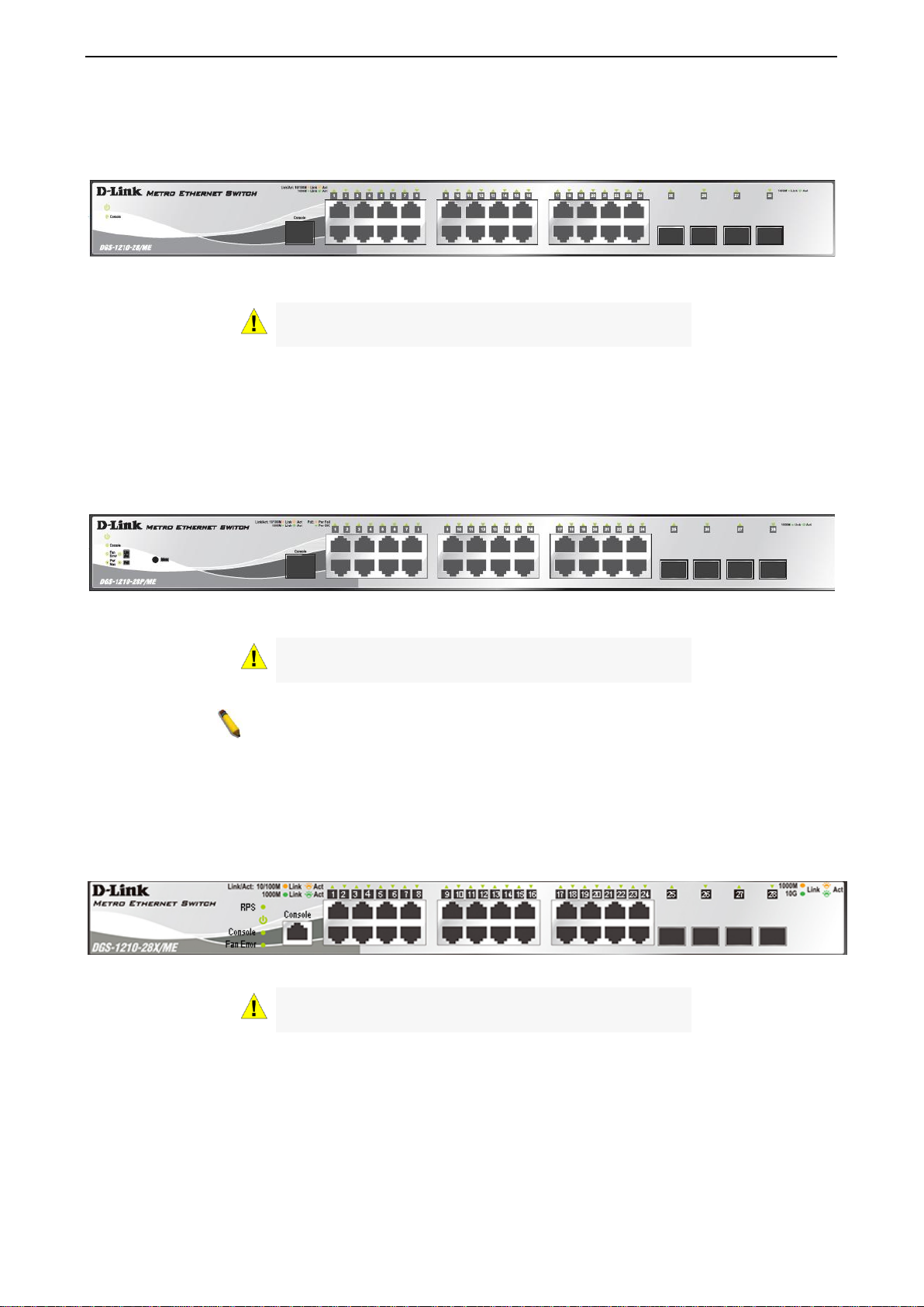
The front panel of the DGS-1210-28XS/ME switch consists out of the following:
• 24 100/1000Mbps SFP port
• 4 1000Mbps/10G SFP+ ports
• One RJ-45 Console Port
• LEDs for Power, Console, Fan Error,RPS, Link/Act for port 1 to 28
4
Page 13
1 Product Introduction DGS-1210 series Metro Ethernet Managed Switch User Manual
listed Optical
NOTE: The power budget is 193 Watts for DGS-1210-52P/ME.
Figure 1.7 – DGS-1210-28XS/ME Front Panel
CAUTION: The MiniGBIC ports should use UL listed
Optical Transceiver product, Rated Laser Class I. 3.3Vdc.
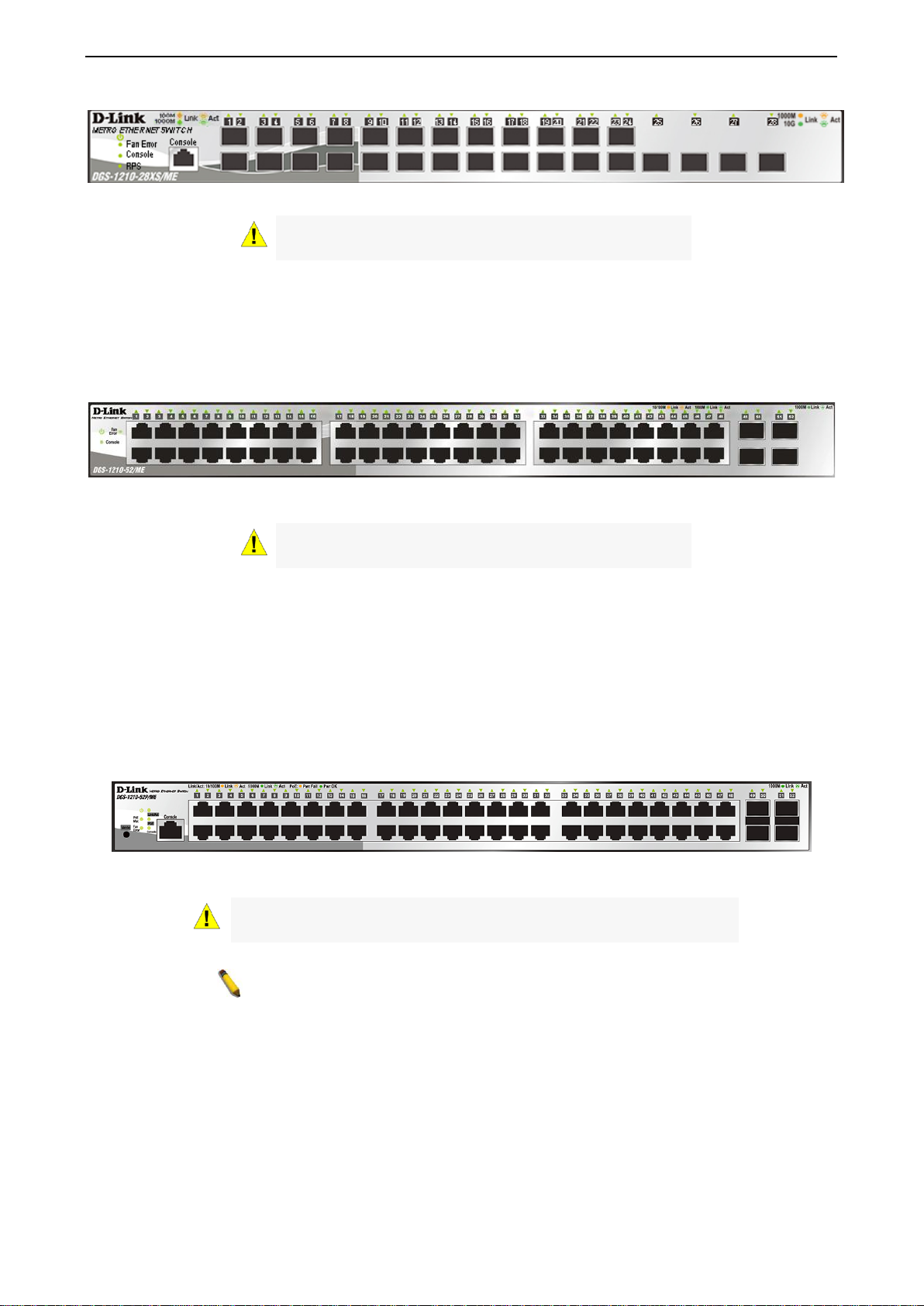
The front panel of the DGS-1210-52/ME switch consists out of the following:
• 48 10/100/1000Mbps Copper Ports
• 4 1000Mbps SFP ports
• LEDs for Power, Console, Fan Error , Link/Act for port 1 to 52
Figure 1.8 – DGS-1210-52/ME SERIES Front Panel
CAUTION: The MiniGBIC ports should use UL listed
Optical Transceiver product, Rated Laser Class I. 3.3Vdc.
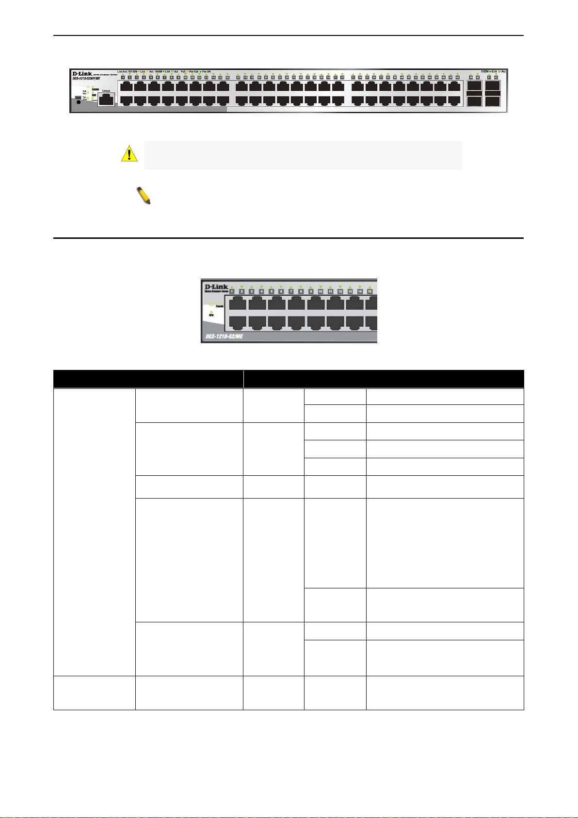
The front panel of the DGS-1210-52P/ME switch consists out of the following:
• 48 10/100/1000Mbps Copper Ports
• 24 10/100/1000Mbps PoE ports
• 4 1000Mbps SFP ports
• One RJ-45 Console Port
• LEDs for Power, Console, Fan Error, PoE Max, Link/Act for port 1 to 52
• Mode: By pressing the Mode button, the Port LED will switch between Link/Act and PoE modes
Figure 1.9 – DGS-1210-52P/ME SERIES Front Panel
CAUTION: The MiniGBIC ports should use UL
Transceiver product, Rated Laser Class I. 3.3Vdc.
The front panel of the DGS-1210-52MP/ME switch consists out of the following:
• 48 10/100/1000Mbps Copper and PoE Ports
• 4 1000Mbps SFP ports
• One RJ-45 Console Port
• LEDs for Power, Console, Fan Error, PoE Max, Link/Act for port 1 to 52
• Mode: By pressing the Mode button, the Port LED will switch between Link/Act and PoE modes
55
Page 14
1 Product Introduction DGS-1210 series Metro Ethernet Managed Switch User Manual
listed Optical
NOTE: The power budget is 370 Watts for DGS-1210-52MP/ME.
The fan has runtime failure and is
brought offline.
The Pwr/PoE Max LED lights up
Switch
device can be supported.
When the system power usage
range.
Mbps
Solid Green
When there is a secure 1000Mbps
of the ports.
Figure 1.10 – DGS-1210-52MP/ME SERIES Front Panel
CAUTION: The MiniGBIC ports should use UL
Transceiver product, Rated Laser Class I. 3.3Vdc.
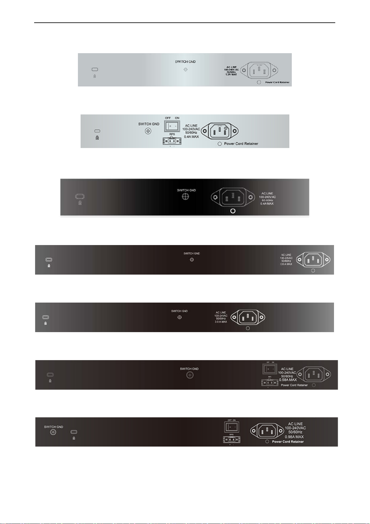
LED Indicators
The Switch supports LED indicators for Power, Console, Fan, and Link/Act for each port. The following
shows the LED indicat ors for the DGS-1210/ME Metr o Ethernet Switch along with an explanation of each
indicator.
Figure 1.11 –LED Indicators on DGS-1 210/ME SERIES
Location LED Indicative Color Status Description
Solid Light Power on.
Power
Green
Light off Power off.
Solid Light Console on.
Console
Green
Blinking POST is in progress.
Light off Console off.
Fan Error
Red Solid light
when the total PoE output of
Per Device
Pwr/PoE Max.
(DGS-1210-
10P/28P/52P/52MP/ME
only)
Solid light
Red
Light off
reached or exceeded 71 Watts for
DGS-1210-10P/ME, 186 Watts for
DGS-1210-28P/52P/ME, and 363
Watts for DGS-1210-52MP/ME. In
the meantime, no additional PoE
does not reach the guard band
RPS
(DGS-1210-
10/12TS/28X/28XS/ME
Green
only)
LED Per
10/100/1000
Link/Act
Green/Amber
Solid Light RPS power on.
Light off RPS power off.
Ethernet connection (or link) at any
6
Page 15

1 Product Introduction DGS-1210 series Metro Ethernet Managed Switch User Manual
Copper Port
Blinking
When there is reception or
Ethernet connected port.
Solid Amber
When there is a secure
(or link) at any of the ports.
Blinking
When there is reception or
Ethernet connected port.
Light off
No link.
Green
Solid Light
Power feeding
Amber
Solid Light
Error Condition
Off
Solid Off
No Power feeding
When there is a secure 1000Mbps
of the ports.
When there is reception or
Ethernet connected port.
When there is a secure 100Mbps
1210-28TX/ME only)
Blinking
Amber
When there is reception or
transmission occurring at the port.
Off
Solid off
No link.
When there is a secure 10Gbps
connection at the port.
Blinking
Green
When there is reception or
transmission occurring at the port.
When there is a secure 1000Mbps
connection at the port.
Blinking
Amber
When there is reception or
transmission occurring at the port.
Off
Solid off
No link.
LED Per
1000Mbps SFP
Port
PoE Mode
Link/Act
Green
Amber
Green
Amber
Solid Green
Blinking
Green
Solid Light
transmission (i.e. Activity—Act) of
data occurring at a 1000Mbps
10/100Mbps Ethernet connection
transmission (i.e. Activity—Act) of
data occurring at a 10/100Mbps
Ethernet connection (or link) at any
transmission (i.e. Activity—Act) of
data occurring at a 1000Mbps
connection at the port. (For DGS-
Solid Light
Green
LED Per SFP +
Port
Link/Act
Solid Light
Amber
Rear Panel Description
The rear panel of the Sw itch conta ins an AC p ower co nnector . The AC po wer co nnec tor is a stan dard thr eepronged connector th at supports the power c ord. Plug-in the fem ale connector of the prov ided power cord
into this socket, and the male s ide of t he c ord into a power outl et. The Switch autom aticall y adjus ts its po wer
setting to any suppl y voltage in the range from 100 to 240 VAC at 50 to 60 Hz. Connect the Kensingtoncompatible securit y lock, at the rear of the switch, to a secur e immovable device. Insert the lock into the
notch and turn the key to secure the lock.
The rear panel also includes an outlet for an optiona l external power supply a nd one RJ-45 console port.
When a power failure occurs, the optional external RPS will immediately and automatically assume the
power supply for the Switch.
DGS-1210-10/ME
Figure 1.12- DGS-1210-10/ME Rear Panel
77
Page 16
1 Product Introduction DGS-1210 series Metro Ethernet Managed Switch User Manual
DGS-1210-10P/ME
Figure 1.13- DGS-1210-10P/ME Rear Panel
DGS-1210-12TS/ME
Figure 1.14- DGS-1210-12TS/ME Rear Panel
DGS-1210-20/ME
DGS-1210-28/ME
DGS-1210-28P/ME
DGS-1210-28X/ME
DGS-1210-28XS/ME
Figure 1.15- DGS-1210-20/ME Rear Panel
Figure 1.16-DGS-1210-28/ME Rear Panel
Figure 1.17 - DGS-1210-28P/ME Rear Panel
Figure 1.18- DGS-1210-28X/ME Rear Panel
Figure 1.19- DGS-1210-28XS/ME Rear Panel
8
Page 17

1 Product Introduction DGS-1210 series Metro Ethernet Managed Switch User Manual
DGS-1210-52/ME
Figure 1.20 - DGS-1210-52/ME Rear Panel
DGS-1210-52P/ME
Figure 1.21 - DGS-1210-52P/ME Rear Panel
DGS-1210-52MP/ME
Figure 1.22 - DGS-1210-52MP/ME R ear Panel
Side Panel Description
The left- and right-hand panels of the Switch have he at v ents t o d is sipat e h eat. Do no t b loc k t hese op eni ng s ,
and leave at least 6 inches of spac e at the rear and sides of the Switch f or proper ventila tion. Be rem inded
that without proper heat diss ipation and a ir cir culatio n, s ystem com ponents m ight overh eat, whic h could lead
to system failure.
Figure 1.23 - Side panels of the DGS-1210/ME SERIES
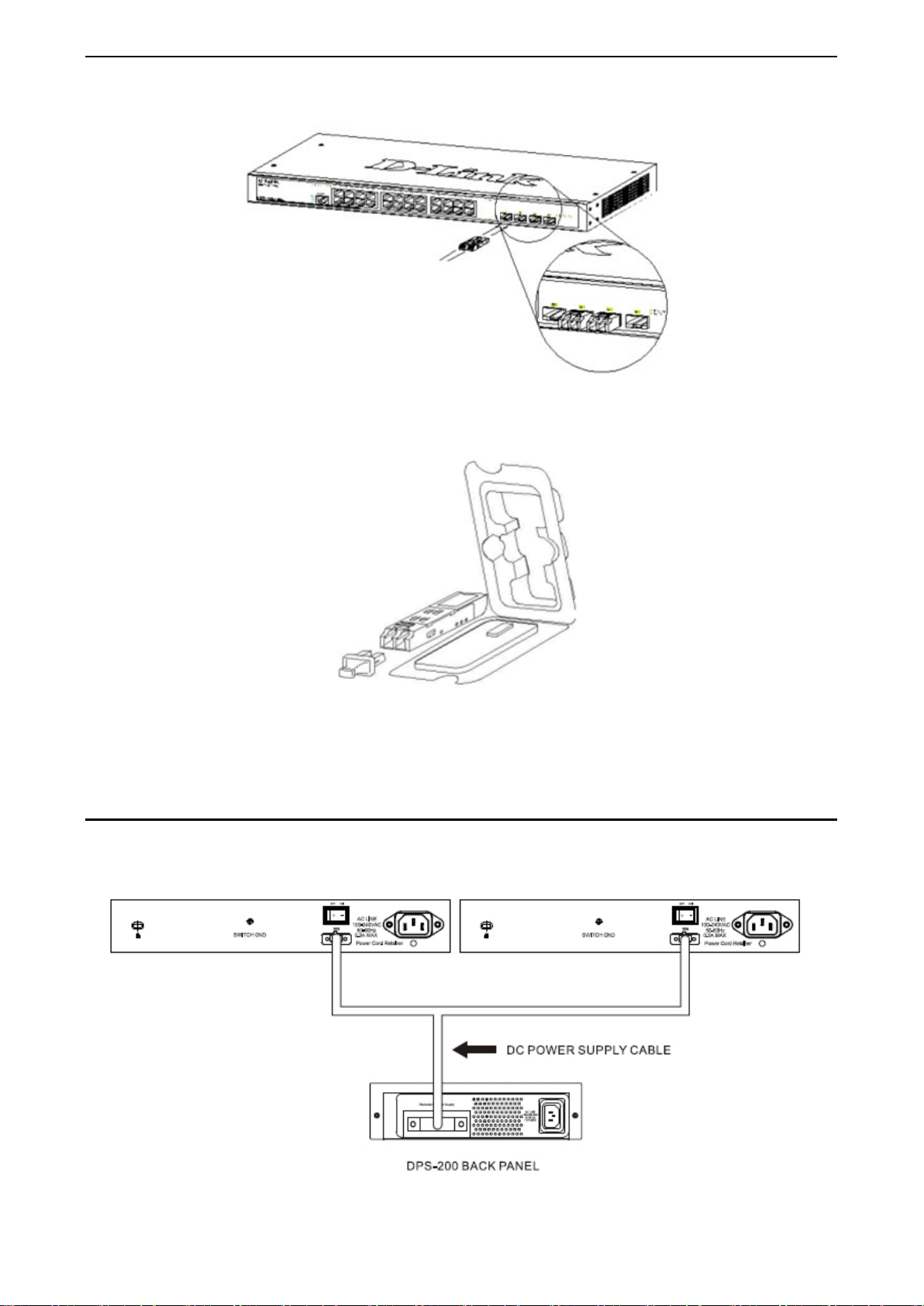
Gigabit Fiber Ports
The DGS-1210/ME Series f eatures support four Small For m Factor Portable (SF P) ports (opt ional). See the
diagram below to view the four SFP port modules being plugged into the Switch.
99
Page 18
1 Product Introduction DGS-1210 series Metro Ethernet Managed Switch User Manual
Figure 1.24 - Inserting the SFP modules into the Switch
Figure 1.25 - Installing the SFP Module
The Switch is equipped with SF P ports , whic h are to b e used with fib er-optical transceiver c abling in order to
uplink various other networking devices for a gigabit link that may span great distances.
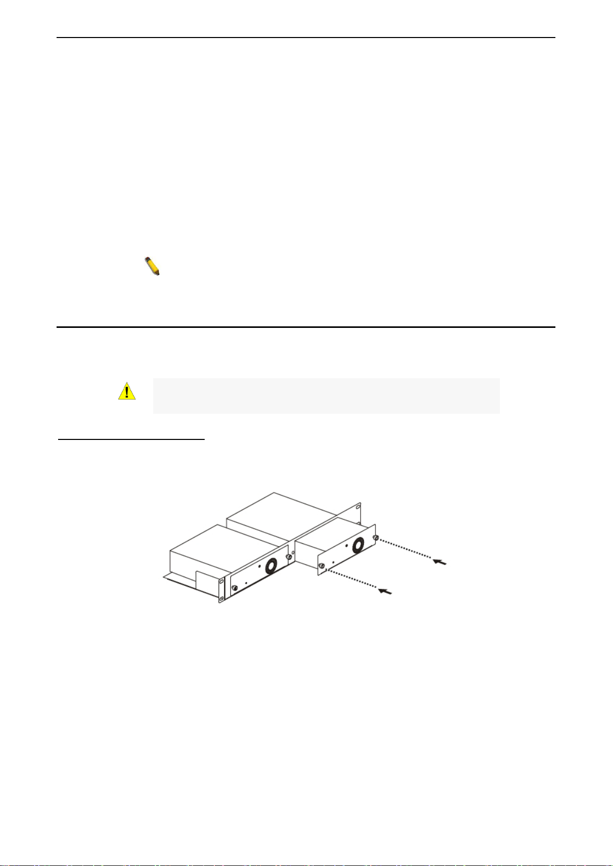
Connecting the DPS-200A/500A to t he RPS Port (for DGS-1210-10/12TS/28X/28XS/ME only)
The DPS-200A/500A redun dant power s uppl y can be connec ted to the RP S port of the Switch usin g the DC
power supply cord, c alled t he D PS-CB150-2PS. It is im portant to n otice that t he DPS-200A/500A can supply
power to one or two DGS-1210-10/ME at the same time.
Figure 1.26 – Connecting two Switches to the DPS-200A/500A
10
Page 19
1 Product Introduction DGS-1210 series Metro Ethernet Managed Switch User Manual
NOTE: See the DPS-200A/500A Quick Installation Guide for more
information.
CAUTION: DO NOT connect the RPS to the AC power before the DC
power is connected might damage the internal power supply.
The following section explains how to connect the DPS-200A/500A to the Switch.
• Disconnect the Switch from the main AC power source.
• Insert the 14-pin end of the DPS-CB150-2PS into the DPS-200A/500A and the 2-pin end into the
receptacle of the RPS port on the Switch.
• Using a standard AC power cord, connect the DPS-200A/500A to the main AC power source. A
green LED on the front panel of the DPS-200A/500A will illuminate to indicate a successful
connection.
• Make sure that the ON/OFF toggle switch on the rear panel of the Switch is turned on.
• Re-connect the Switch to the AC power source and power on the DPS-200A/500A.
No configuration is needed in the Switch software for this installation.
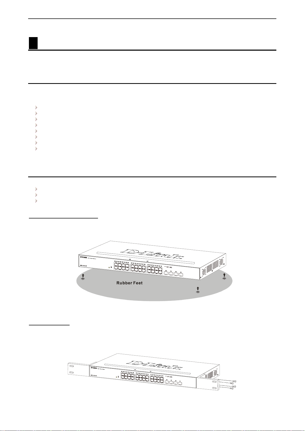
Installing the RPS into a Rack-mount Chassis (for DGS-1210-10/12TS/28X/28XS/ME only)
The DPS-200A/500A are the redundant power supply unit designed to conform to the voltage requirements
of the RPS port of the Switch being supported. The DPS-200A/500A can be installed into a DPS-800 rackmount chassis unit.
power cable is connected. Connecting the AC power before the DC
DPS-800 Rack-mount Chassis
The DPS-800 is a standard-size rack-mount (1 standard unit in height) designed to hold up to two DPS200A/500A redundant power supplies.
Figure 1.27 –Installing the DPS-200A/500A in the DPS-800
The DPS-800 rack -mount chassis can be m ounted into a standard 19" rac k. Use the following d iagram to
guide you.
1111
Page 20
2 Hardware Installation DGS-1210 series Metro Ethernet Managed Switch User Manual
2 Hardware Installation
This chapter provides unpacking and installation information for the D-Link DGS-1210/ME Metro Ethernet
Switch.
Step 1: Unpacking
Open the shipping carton and carefully unpack its contents. Please c onsult the packing list located in the
User Manual to mak e sure all i tems are present and u ndamaged. If an y item is missing or dam aged, pleas e
contact your local D-Link reseller for replacement.
One D-Link Metro Ethernet Switch
One multi-language Getting Started Guide
One CD
One RJ-45 console cable
Power cord clip
Power cord
Rack mount kit
Rubber feet
If any item is found missing or damaged, please contact the local reseller for replacement.
Step 2: Switch Installation
For safe switch installation and operation, it is recommended that you:
Visually inspect the power cord to see that it is secured fully to the AC power connector.
Make sure that there is proper heat dissipation and adequate ventilation around the switch.
Do not place heavy objects on the switch.
Desktop or Shelf Installation
When installing the switc h on a desktop or shelf, the r ubber feet included w ith the device must be attac hed
on the bottom at each cor ner of the device’s base. All ow enough ventilatio n space between the dev ice and
the objects around it.
Figure 2.1 – Attach the adhesive rubber pads to the bottom
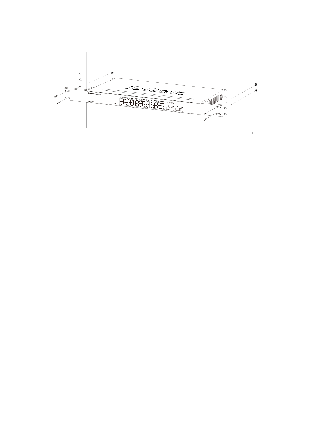
Rack Installation
The switch can be mounted in an EIA standard size 19-inch r ack, which can be plac ed i n a wirin g closet with
other equipment. T o install, attac h the m ounting br ackets to th e switc h’s side p anels (one on each s ide) and
secure them with the screws provided (please note that these brackets are not designed for palm size
switches).
12
Page 21
2 Hardware Installation DGS-1210 series Metro Ethernet Managed Switch User Manual
Figure 2.2 – Attach the mounti ng brackets to the Switch
Then, use the screws provided with the equipment rack to mount the switch in the rack.
Figure 2.3 – Mount the Switch in the rack or chassis
Please be aware of following safety Instructions when installing:
A) Elevated Operat ing Ambient - If instal led in a closed or multi-u nit rack assembly, the op erating ambient
temperature of the rac k environm ent ma y be greater than room ambient. T herefor e, considera tion should b e
given to installing the equ ip ment in an environment compatible with the maximum ambient temperature (Tma)
specified by the manufacturer.
B) Reduced Air Flow - Installation of the equipment in a rack should be such that the amount of air flow
required for safe operation of the equipment is not compromised.
C) Mechanical Loading - Mounting of the equipm ent in the r ack s hould be such th at a hazar dous c onditio n is
not achieved due to uneven mechanical loading.
D) Circuit Overloading - Consideration should be given to the connection of the equipment to the supply
circuit, and the ef fect that o verloadin g of the circu its m ight have on over current pr otection a nd suppl y wiring.
Appropriate consideration of equipment nameplate ratings should be used when addressing this concern.
E) Reliable Earthing - Reliable earthing of rack-mounted equipment should be maintained. Particular
attention should be give n to supply connecti ons other than direct c onnections to the branch c ircuit (e.g. use
of power strips)."
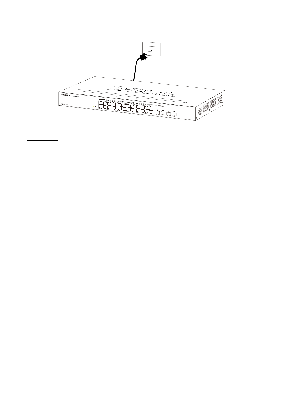
Step 3 – Plugging in the AC Power Cord
Users may now connect th e AC power cord into the r ear of the switch an d to an electrical outlet (pr eferably
one that is grounded and surge protected).
1133
Page 22
2 Hardware Installation DGS-1210 series Metro Ethernet Managed Switch User Manual
Figure 2.4 – Plugging the switch into an outlet
Power Failure
As a precaution, th e switch s hould be u nplugged in cas e of power f ailure. W hen po wer is resum ed, plug t he
switch back in.
14
Page 23

3 Getting Started DGS-1210 series Metro Ethernet Managed Switch User Manual
3 Getting Started
This chapter introduces the management interface of D-Link DGS-1210/ME Metro Ethernet Switch.
Management Options
Using Web-based Managemen t
Connecting to the Console Port
Management Options
The D-Link DGS-1210/ME Metro Ethernet Switch can be m anaged through an y port on the device by using
the Web-based Management, out-of band through the console port on the front/back panel and in-band
using Telnet
Each switch must be assigned its own IP Address , which is used for comm unication with the Web-Based
Management or a SNMP net work manager. The PC should have an IP addr ess in the same range as the
switch. Each switch can allow up to four users to access the Web-Based Management concurrently.
Please refer to the following installation instructions for the Web-based Management.
Using Web-based Management
After a successf ul ph ysica l ins ta lla tio n, you can configure the Switch, monitor the network status , an d d is play
statistics using a web browser.
Supported Web Browsers
The embedded Web-based Management currently supports the following web browsers:
Internet Explorer 6/7 or later version
Netscape 8 or later version
Mozilla
Firefox 1.5/2.0 or later version
Chrome 5.0 or later version
Safari 4.0 or later version
Connecting to the Switch
You will need the following equipment to begin the web configuration of your device:
1. A PC with a RJ-45 Ethernet connection
2. A standard Ethernet cable
Connect the Ethernet cable to any of the ports on the front panel of the switch and to the Ethernet port on the
PC.
Figure 3.1 – Connected Ethernet cable
15
Page 24
3 Getting Started D-Link DGS-1210-52/ME-28/ME Use r
Manual
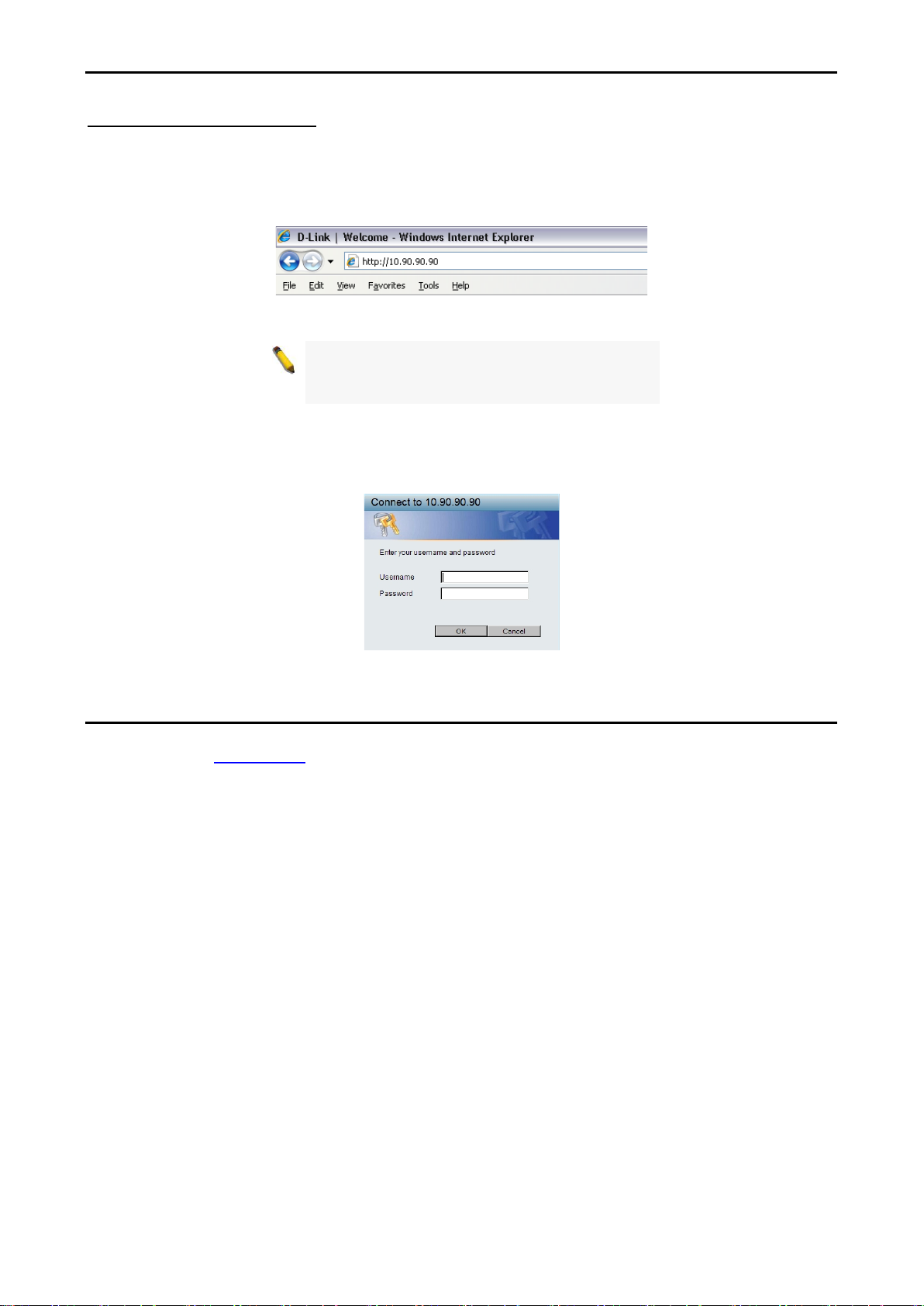
Login Web-based Management
In order to login and config ure the s witch vi a an Ether net conn ectio n, the PC must have an IP addres s in t he
same subnet as the s witc h. For example, if the switch has an IP address of 10.90.90.90, the PC should have
an IP address of 10.x.y.z (where x/y is a num ber betw een 0 ~ 254 and z is a number betwee n 1 ~ 254), and
a subnet mask of 255.0.0.0. Enter 10.90.90.90 (the factory default IP address) in the address bar of your
web browser and press <Enter>.
Figure 3.2 –Enter the IP address 10.90.90.90 in the web browser
NOTE: T he switch's f actor y default IP addres s is
10.90.90.90 with a subne t m ask of 255.0.0 .0 and
a default gateway of 0.0.0.0.
When the following logon dialog box appears, enter the password and choose the language of the W ebbased Management interface then click OK.
By default, the Username and Password are empty.
Figure 3.3 – Logon Dia log Box
Web-based Management
By clicking th e OK button in Logon Dialog Box , you wi ll enter the Web-based Managem ent interface. Please
refer to Chapter 4 Configuration
for detailed instructions.
16
Page 25
4 Configuration DGS-1210 series Metro Ethernet Managed Switch User Manual
If you close the web browser without
4 Configuration
The features and functions of the D-Link DGS-1210/ME Metro Ethernet Switch can be configured for
optimum use through the Web-based user interface.
Web-based Management
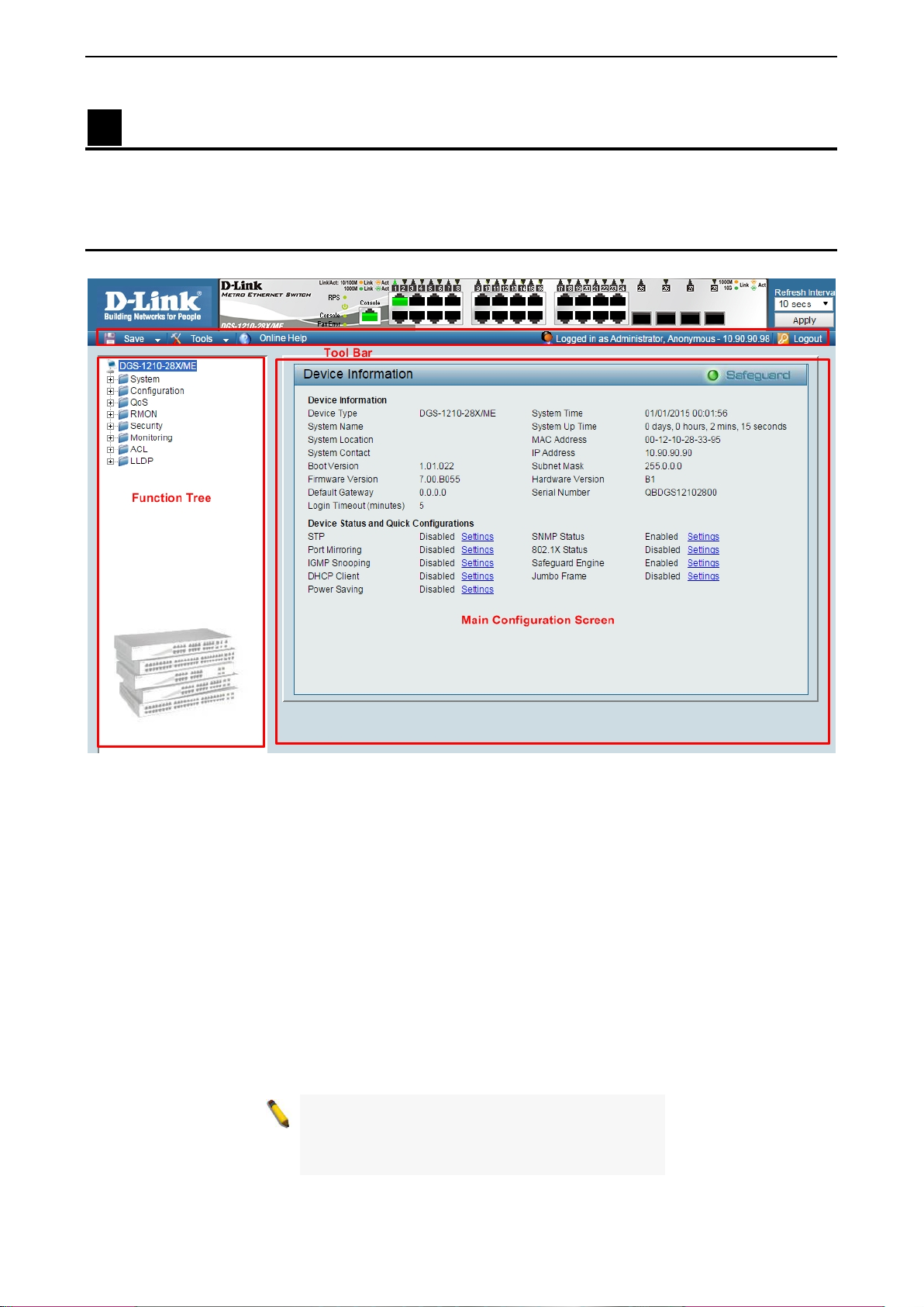
After press the OK butt on i n Logon Dialog Box, you will see the screen below:
Figure 4.1 – Web-based Management
The above image is the Web-based Management screen. The three main areas a r e the Tool Bar on top, the
Function Tree, and the Main Configuration Screen.
The Tool Bar provides a quick and convenient way for essential utility functions like firmware and
configuration management.
By choosing different functions in the Function Tree, you can change all the settings in the Main
Configuration Screen. The main configuration s cr ee n wil l show the current stat us of your Switch by click ing
the model name on top of the function tree.
At the upper right corner of the screen the username and current IP address will be displayed.
Under the username is the Logout button. Click this to end this session.
NOTE:
clicking th e Logout button first, then it will be s e en
as an abnormal ex it and the log in session will s till
be occupied.
17
Page 26
4 Configuration DGS-1210 series Metro Ethernet Managed Switch User Manual
Finally, b y clic k ing on the D-Link logo at the upper-left corner of the screen you will be redirected to th e local
D-Link website.
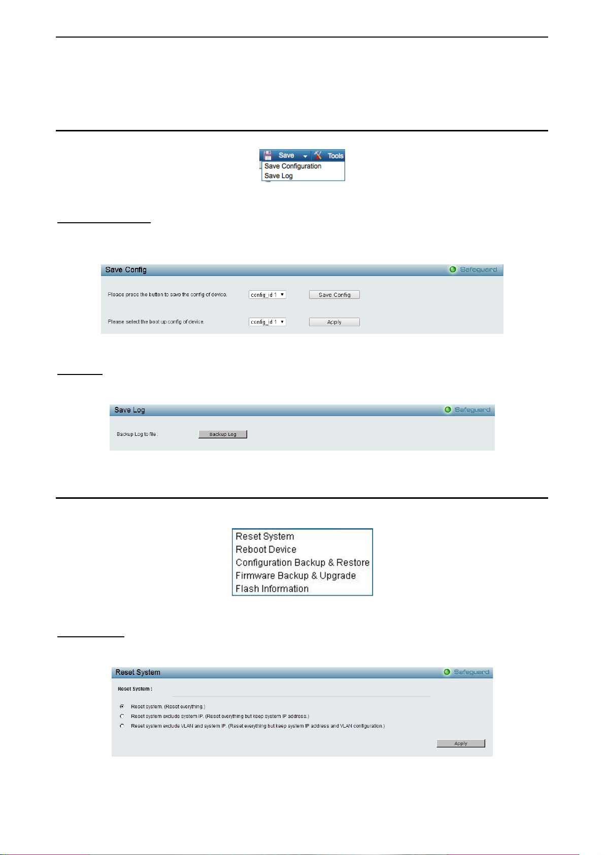
Tool Bar > Save Menu
The Save Menu provides Save Configuration and Save Log functions.
Figure 4.2 – Save Menu
Save Configuration
Select to save the e ntire configuration cha nges you have made of t he device to switch’s non-volatile RAM
then click Save Config but ton to take effec t. Or select to boo t up the device f rom which configur ation of the
device then click the Apply button to take effect.
Figure 4.3 – Save Configuration
Save Log
Save the log entries to your local drive and a pop-up mess age will prom pt you for the file pa th. You c an vie w
or edit the log file by using text editor (e.g. Notepad).
Figure 4.4 – Save L og
Tool Bar > Tool Menu
The Tool Menu off ers global functi on controls suc h as Res et System, Reboot De vice, Conf iguration Back up
and Restore, Firmware Backup and Upgrade and Flash Information.
Figure 4.5 – Tool Menu
Reset System
Provide another safe res et option for the Switch. A ll configuration settings in non-volatile RAM will reset to
factory default and the Switch will reboot.
Figure 4.6 – Tool Menu > Reset System
18
Page 27
4 Configuration DGS-1210 series Metro Ethernet Managed Switch User Manual
Select the different reset method then click Apply to reset the system.
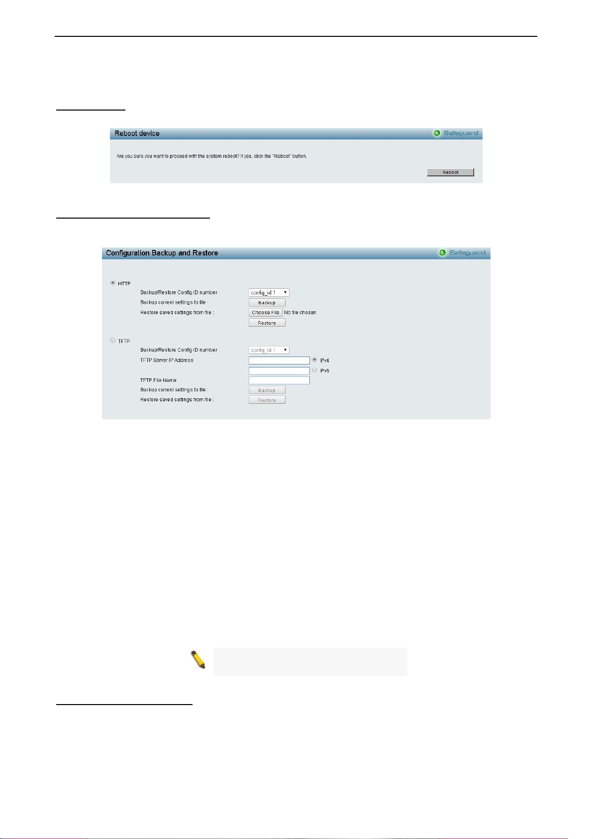
Reboot Device Provide a safe way to reboot the system. Click Reboot to restart the switch.
Figure 4.7 – Tool Menu > Reboot Device
Configuration Backup & Restore
Allow the current configuration settings to be saved t o a file (not including the password), and if necessary,
you can restore configuration settings from this file. Two methods can be selected: HTTP or TFTP.
Figure 4.8 – Tool Menu > Configuration Backup and Restore
HTTP: Backup or restore the configuration file to or from your local drive.
Backup/Restore Config ID number: Specify the configuration ID number to be backup or restored.
Click Backup to save the current settings to your disk.
Click Browse to browse your inventories for a saved backup settings file.
Click Restore after selecting the backup settings file you want to restore.
TFTP: TFTP (Trivial File Transfer Protocol) is a file transfer protocol that allows you to transfer files to a
remote TFTP server. The maximum Telnet Server connection is 4.
Backup/Restore Config ID number: Specify the configuration ID number to be backup or restored.
TFTP Server IP Address: Specif y the IPv4 or IPv6 addr ess .
TFTP File Name: Enter the file name which you want to save/restore from for the configuration.
Click Backup to save the current settings to the TFTP server.
Click Restore after selecting the backup settings file you want to restore.
Note: Switch will reboot after restore, and
all current configurations wi ll be lost.
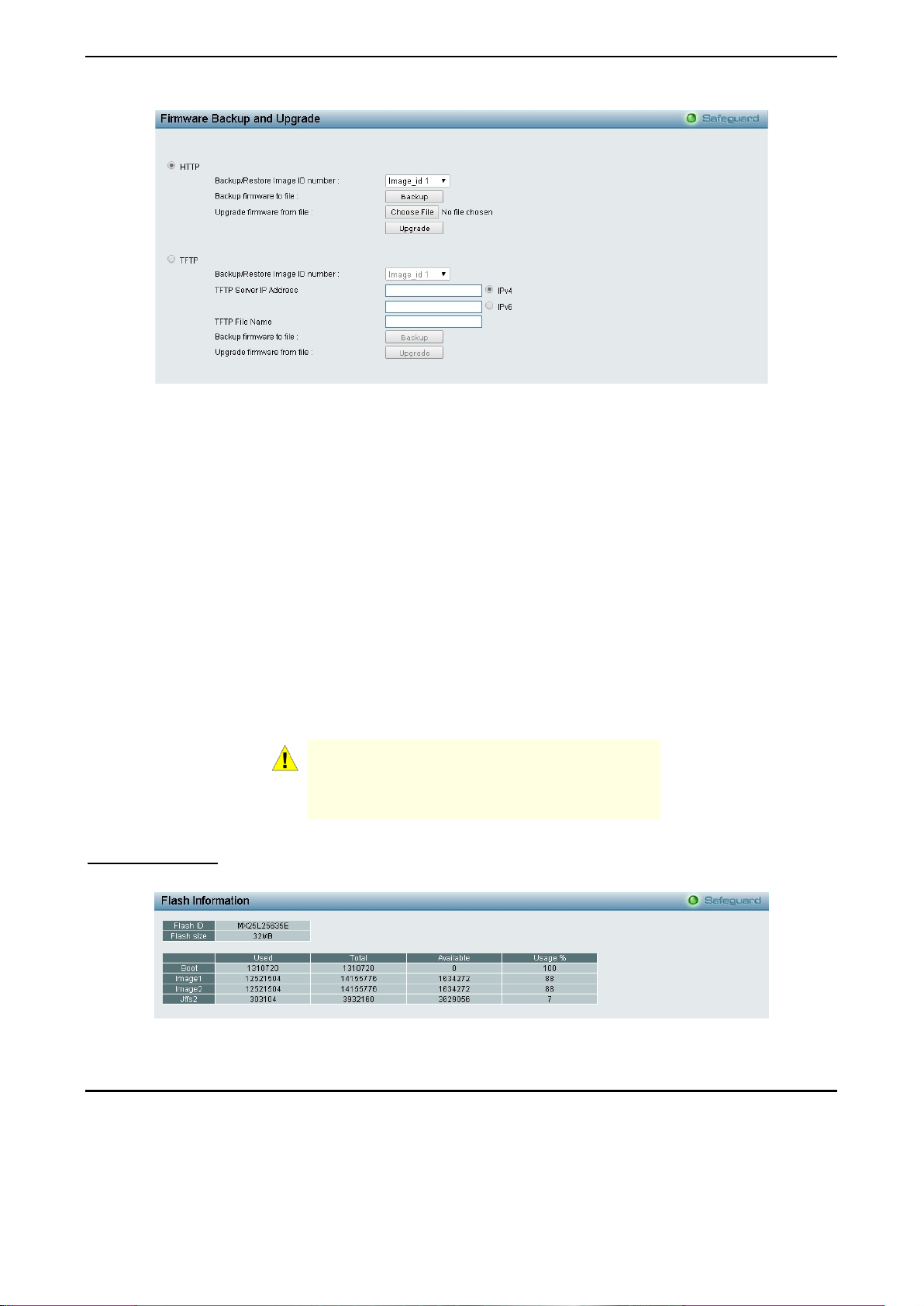
Firmware Backup & Upgrade
Allow for the firmware to be saved, or for an existing firmware file to be uploaded to the Switch. Two methods
can be selected: HTTP or TFTP.
1199
Page 28
4 Configuration DGS-1210 series Metro Ethernet Managed Switch User Manual
Figure 4.9 – Tool Menu > Firmware Backup and Upgrade
HTTP: Backup or upgrade the firmware to or from your local PC drive.
Backup/Restore Image ID number: Specify the firmware image ID number to be backup or restored.
Click Backup to save the firmware to your disk.
Click Browse to browse your inventories for a saved firmware file.
Click Upgrade after selecting the firmware file you want to restore.
TFTP: Backup or upgrade the firmware to or from a remote TFTP server. The maximum Telnet Server
connection is 4.
Backup/Restore Image ID number: Specify the firmware image ID number to be backup or restored.
TFTP Server IP Address: Specif y the IPv4 or IPv6 addr ess .
TFTP File Name: Enter the file name which you want to save/restore from for the firmware.
Click Backup to save the firmware to the TFTP server.
Click Upgrade after selecting the firmware file you want to restore.
CAUTION: Do n ot disconnect the PC or remove
the power cord from device until the upgrade
completes. The Switch may crash if the
Firmware upgrade is incomplete.
Flash Information
The Flash Information page displays the detail information of flash on the Switch.
Figure 4.10 – Tool Menu > Flash Information
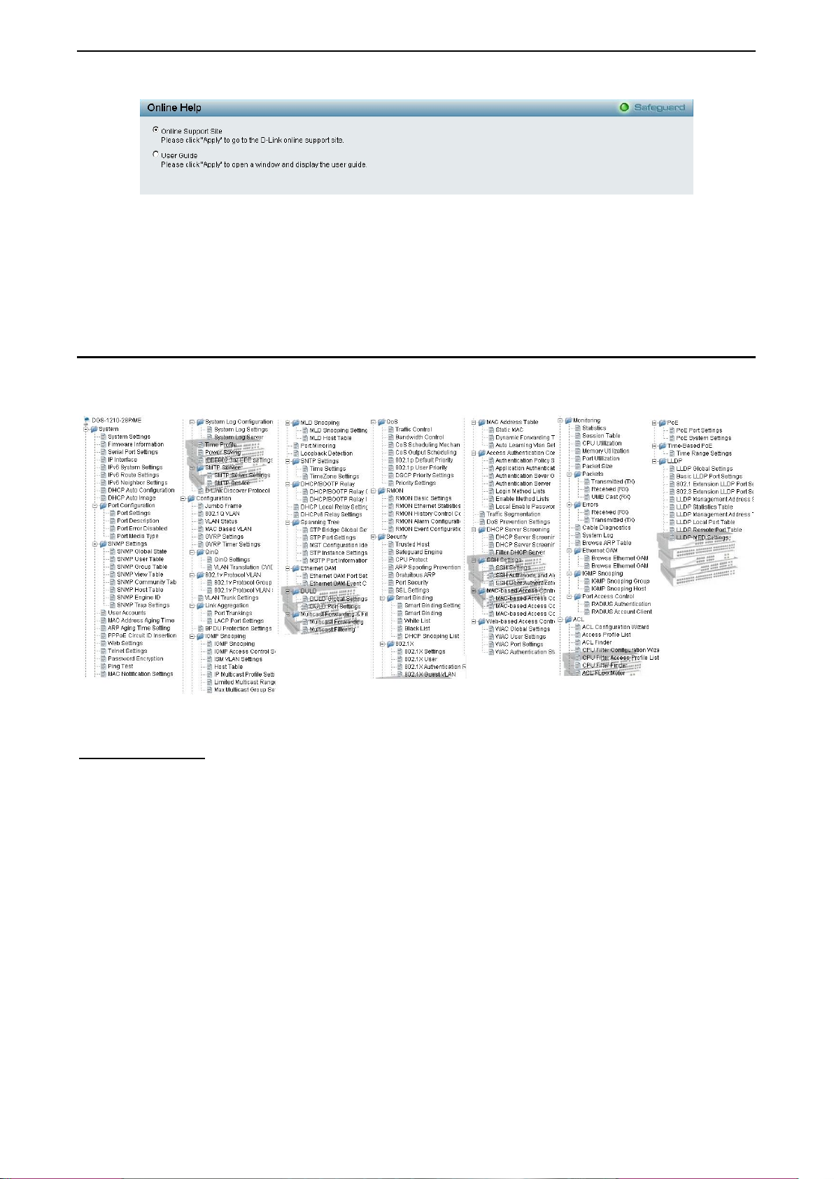
Tool Bar > Online Help
The Online Help provides two ways of online support:
20
Page 29
4 Configuration DGS-1210 series Metro Ethernet Managed Switch User Manual
Figure 4.11 – Online Help
D-Link Support Site: This will lead you to the D-Lin k website where you can find on line reso urces suc h as
updated firmware images.
User Guide: This can offer an immediate reference for the feature definition or configuration guide.
Click Apply to make configuration effected.
Function Tree
All configuration opt ions on the switch are ac cessed throug h the Setup menu on the left side of the screen.
Click on the setup item that you want to configure. The following s ections provid e more detailed description
of each feature and function.
Figure 4.12 –Function Tree
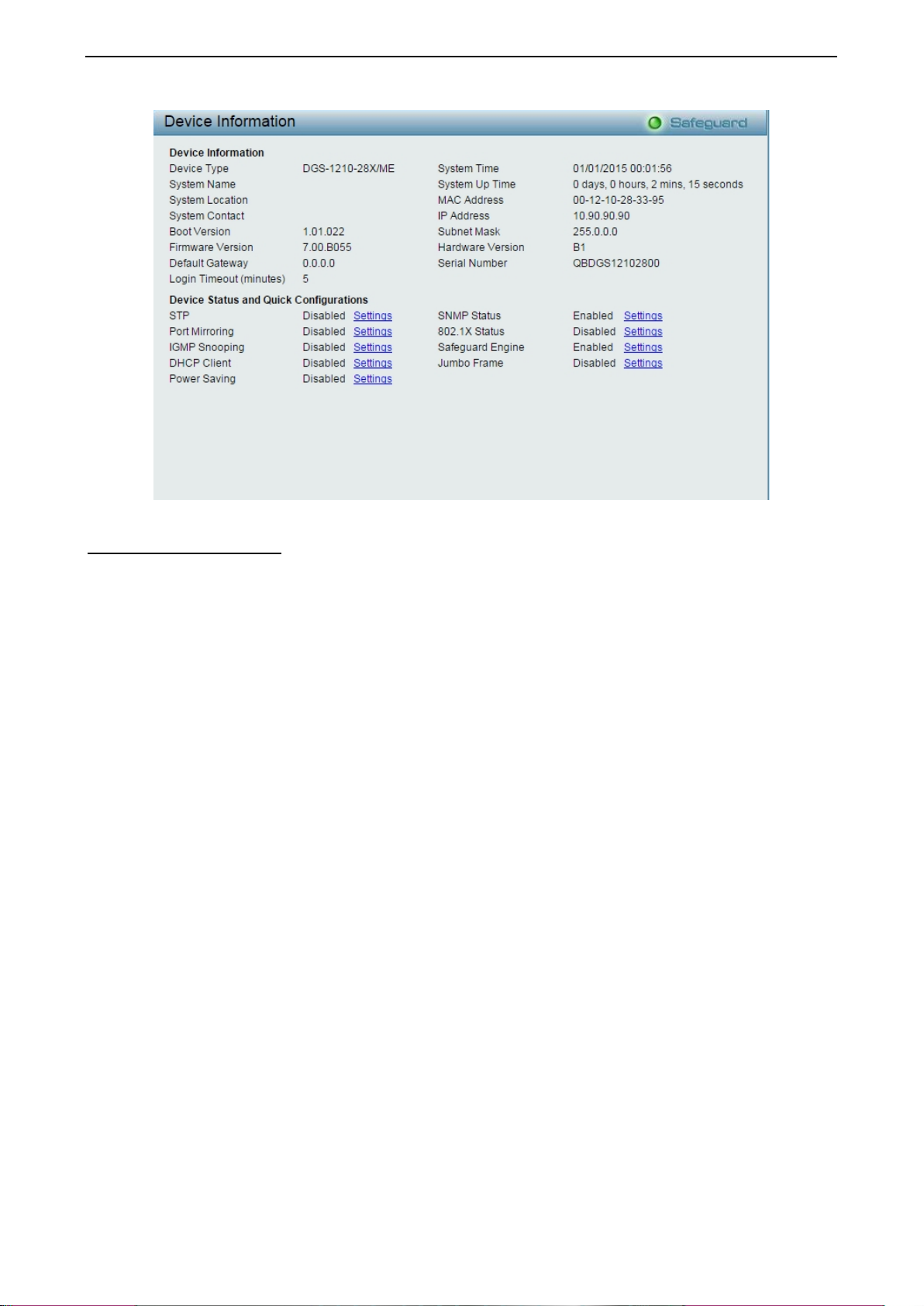
Device Information
The Device Inform ation pro vides an overvie w of the s witch, including essentia l inf ormation suc h as f irmware
& hardware information, and IP address.
It also offers an overall status of common software features:
STP: Click Settings to link to Configuration > Spanning Tree > STP Bridge Global Settings. Default is
disabled.
Port Mirroring: Click Settings to link to Configuration > Port Mirroring. Def ault is dis ab led .
IGMP Snooping: Click Settings to link to Configuration > IGMP Snooping > IGMP Snooping. Default is
disabled.
DHCP Client: Click Settings to link to System > System Settings. Default is disabled.
Power Saving: Click Settings to link to System > Power Saving. Default is disabled.
SNMP Status: Click Settings to link to System > SNMP Settings > SNMP Global State. Default is enabled.
802.1X Status: Click Settings to link to Security > 802.1X > 802.1X Settings. Default is disabled.
Safeguard Engine: Click Settings to link to Security > Safeguard Engine. Default is enabled.
Jumbo Frame: Click Settings to link to Configuration > Jumbo Frame. Default is disabled.
2211
Page 30
4 Configuration DGS-1210 series Metro Ethernet Managed Switch User Manual
Figure 4.13 – Device Information
System > System Settings
The System Setting allows the user to configure the IP address and the basic system information of the
Switch.
IP Information: There are two wa ys for the s witch to obtain an IP address: Static and DHCP (Dynamic Host
Configuration Protocol).
When using static m ode, the IP Address, Subnet Mask, Gateway and DHCP Option 12 State can be
manually configured. W hen using DHCP m ode, the Switch will first lo ok for a DHCP ser ver to provide it with
an IP address (includin g network mask and default gatewa y) b efore using the d efault or previousl y entered
settings. By def ault the IP setting is static mode with IP address is 10.90.90.90 and subnet mask is 255.0.0.0.
System Information: By entering a System Name and System Location, the device can m ore easily be
recognized.
Login Timeout: The Login Timeout controls the idle time-out period for security purposes, and when there is
no action f or a specific time span in th e Web-bas ed Management. If the current ses sion times out (ex pires),
the user is required a re-login before using the Web-based Management ag ain. Selective range is f rom 3 to
30 minutes, and the default setting is 5 minutes.
22
Page 31

4 Configuration DGS-1210 series Metro Ethernet Managed Switch User Manual
Figure 4.14 – System > System Settings
System > Firmware Information
The Firm ware Inform ation page disp lays the i nform ation of firm ware. The user can specif y configurat ion and
image file to boot up when power on the Switch next time.
.
Figure 4.15 – System > Firmware Information
System > Serial Port Settings
The Serial Port Settings allows the user to adjust the Baud Rate and the Auto Logout values.
2233
Page 32

4 Configuration DGS-1210 series Metro Ethernet Managed Switch User Manual
.
Figure 4.16 – System > Firmware Information
Baud Rate: Specify the b aud rate for the serial port on the Switch. There are four possible baud rates to
choose from, 9600, 1 9200, 38400 and 115200. F or a connection to the S witch using the console por t, the
baud rate must be set to 9600, which is the default setting.
Auto Logout: Select the logout time used for the console interface. This automatically logs the user out after
an idle period of time, as defined. Choose f rom the following options: 2, 5, 10, 15 minutes or Never. The
default setting is 10 minutes.
Date Bits: Display the date bits used for the serial port connection.
Parity Bits: Display the parity bits used for the serial port connection.
Stop Bits: Display the stop bits used for the serial port connection.
System > IP Interface
The IP Interface page allow user to configure the IPv6 system settings.
.
Figure 4.17 – System > IP Interface
Interface Name: Specifies the name of IP interface.
VLAN Name: Specifies the VLAN name of IP interface.
IPv4 Address: Specifies the IPv4 address for the interface.
Netmask: Select the netmask of IP address.
Interface Admin State: Enables or disables the interface administration state.
Click Add for the settings to take effect.
System > IPv6 System Settings
The IPv6 System Settings page allow user to configure the IPv6 system information.
24
Page 33

4 Configuration DGS-1210 series Metro Ethernet Managed Switch User Manual
.
Figure 4.18 – System > IPv6 System Settings
IPv6 System Settings:
Interface Name: Displays the interface name of IPv6.
IPv6 State: Specifies the IPv6 to be enabled or disabled.
DHCPv6 Client: Specifies the DHCPv6 client to be enabled or disabled.
IPv6 Network Address: Specifies the IPv6 Network Address.
NS Retransmit Time Settings:
NS Retransmit Time ( 1-3600): Enter the N eighbor solicitation’s retrans mit timer in second here. Specifies
the NS retransmit time for IPv6. The field range is 1-3600, and default is 1 second.
Automatic Link Local State Settings:
Automatic Link Local Address: Specifies the automatic link is enabled or disabled.
Click Apply for the settings to take effect.
System > IPv6 Route Settings
The IPv6 Route Settings page allows user to configure the IPv6 route settings.
Figure 4.19 – System > IPv6 Route Settings
IP Interface: Specify the IP interface which to be created.
Default Gateway: The corresponding IPv6 address for the next hop Gateway address in IPv6 format..
Metric: Represents th e metric value of the IP interface entered into the table. T his field m ay read a num ber
between 1 and 65535.
Click Create to accept the changes made, and click the Delete button to remove the entry.
2255
Page 34

4 Configuration DGS-1210 series Metro Ethernet Managed Switch User Manual
System > IPv6 Neighbor Settings
The user can configur e the Switc h’s IPv6 nei ghbor settings . The Switc h’s current IPv6 neighbor settings will
be displayed in the table at the bottom of this window.
Figure 4.20 – System > IPv6 Neighbor Settings
Interface Name: Enter the interface name of the IPv6 neighbor.
Neighbor IPv6 Address: Specifies the neighbor IPv6 address.
Link Layer MAC Address: Specifies the link layer MAC address.
Click Apply for the settings to take effect.
Interface Name: Specifies the in terface name of the IPv 6 neighbor. To searc h for all the current interf aces
on the Switch, go to t he se cond In terfac e Nam e f ield in the m iddle part of the windo w, tick the All chec k box.
Tick the Hardware option to display all the neighbor cache entries which were written into the hardware table.
State: Use the drop-down menu to select All, Address, Static or Dynam ic. When the user selects address
from the drop-down menu, the user will be able to enter an IP address in the space provided next to the state
option.
Click Find to locate a specific entry based on the information entered.
Click Clear to clear all the information entered in the fields.
System > DHCP Auto Configuration
This page allows you to enable the DHCP Auto Configuration feature on the Switch. When enabled, the
Switch becomes a DHCP cl ient and gets the configuration file f rom a TFTP server automatically on next boot
up. To accomplish this, the DHCP server m ust deliver the TFTP server IP address and configuration file
name information in the DHCP reply packet. The TFTP server must be up and running and store the
necessary configuration file in its base directory when the request is received from the Switch.
Figure 4.21 – System > DHCP Auto Configuratio n
System > DHCP Auto Image
The DHCP Auto Image page allows user to automatically download FW Image and u pgrade the different
firmware version image into the Switch.
Figure 4.22 – System > DHCP Auto Image
26
Page 35

4 Configuration DGS-1210 series Metro Ethernet Managed Switch User Manual
Be sure to adjust port speed settings
System > Port Configuration > Port Settings
In the Port Setting page, the status of all ports c an be m onitored an d adjusted f or optim um conf iguration. B y
selecting a range of por ts (From Po rt and To Po rt), the Speed can be set f or all selected por ts by clicking
Apply. Press the Refresh button to view the latest information.
Figure 4.23 – System > Port Configuration > Port Settings
Media: Depending on the selected port type, two options for user. Copper and Fiber_1G.
State: Enable or disable the state of specified ports.
Speed: Gigabit Fiber conn ections can operate in 1000M F ull Force Mode, Auto Mode or Dis abled. Copper
connections can oper ate in Forced Mode s ettings (1000M F ull, 100M Full, 100M Half, 10M Full, 10M Half),
Auto, or Disabled. The default setting for all ports is Auto.
NOTE:
appropriately after changing the connected cable
media types.
MDI/MDIX:
A medium dependent interface (MDI) port is an Ethernet port connection typicall y us ed on the Network
Interface Card (NIC) or In tegrated NIC port on a PC. S witches and hubs usually use Medium dependent
interface crossover (MDIX) interface. When connecting the Switch to end stations, user have to use
straight through Ethernet cables to make sure the Tx/Rx pairs match up properly. When connecting the
Switch to other networking devices, a crossover cable must be used.
This switch provides a configurabl e MDI/MDIX function for users. The switches can be se t as an MDI port in
order to connect to other hubs or switches without an Ethernet crossover cable.
Auto is designed on the switch to detect if the c onnection is bac kwards, and au tomatically cho oses MDI or
MDIX to properly match the connection. The default setting is “Auto” MDI/MDIX.
Flow Control: You can enable this func tion to m itigat e the traff ic c ongestion. P orts configur ed for f ull-duplex
use 802.3x flow control, half-duplex ports use backpressure flow control. The default setting is Disabled.
System > Port Configuration > Port Description
In the Port Description page, the user may name various ports on the Switch.
Figure 4.24 – System > Port Configuration > Port Description
2277
Page 36

4 Configuration DGS-1210 series Metro Ethernet Managed Switch User Manual
From Port / To Port: Specify the range of ports to describe.
Medium Type: Depending on the selected port type, two options for user. Copper and Fiber_1G.
Description: Specify the description of ports.
Click Apply to set the description in the table.
System > Port Configuration > Port Error Disabled
The Port Error Disabled page displays the information about ports that have had their connection status
disabled, for reasons such as STP loopback detection or link down status.
Figure 4.25 – System > Port Configuration > Port Error Disabled
Port: Displays the port that has been error disabled.
Port State: Describes the current running state of the port, whether Enabled or Disabled.
Connection Status: This field will read the uplink s tatus of the ind ivid ual por ts, whether Enabled or Disabl ed .
Reason: Describes the reason why the port has been error-disabled, such as a STP loopback occurrence.
System > Port Configuration > Port Media Type
The Port Media Type page displays the information about the port media type.
Figure 4.26 – System > Port Configuration > Port Media Type
Port: Displays the port number.
Type: Displays the port media type. The media types are 1000MBASE-T, 1000MBASE-X, 100MBASE-T,
100MBASE-X, 10MBASE-T and 10MBASE-X.
System > SNMP Settings > SNMP Global State
Simple Network Management Protocol (SNMP) is an OSI Layer 7 (Application Layer) protocol designed
specifically for managing and monitoring networ k devices. SNMP enables ne twork management stations t o
read and modify the settings of gateways, routers, switches, and other network devices. Use SNMP to
configure system features for proper operation, monitor performance and detect potential problems in the
Switch or LAN.
Managed devices t hat support SNMP includ e software (referred t o as an agent), which ru ns locally on the
device. A defined set of variab les (m anaged object s) is m aintained by th e SNM P agen t and used t o m anage
the device. These objec ts are defined in a Managem ent Inform ation Base (MIB), which pro vides a standar d
presentation of the infor mation controlled by the on-bo ard SNM P ag ent. SNM P de f ines both t h e f ormat of the
MIB specifications and the protocol used to access this information over the network.
28
Page 37

4 Configuration DGS-1210 series Metro Ethernet Managed Switch User Manual
The default SNMP global state is disabled. Select Enable and click Apply to enable the SNMP function.
Figure 4.27 – System > SNMP Settings > SNMP Global State
System > SNMP Settings > SNMP User Table
This page is used to maintain the SNMP user tab le f or the use of SNMPv3. SNMPv3 allows or rest ric ts us er s
using the MIB OID, and also encrypts the SNMP messages sent out between users and Switch.
Figure 4.28 – System > SNMP Settings > SNMP User Table
User Name: Enter a SNMP user name of up to 32 characters.
Group Name: Specify the SNMP group of the SNMP user.
SNMP Version: Specify the SNMP version of the user. Only SNMPv3 encrypts the messages.
Encrypt: Specifies the Encrypt is enabled or disabled when the SNMP Version is V3.
Auth-Protocol/Password: Specify either HMAC-MD5-96 or HMAC-SHA to be the authentication protocol.
Enter a password for SNMPv3 encryption in the right colum n.
Priv-Protocol/Password: Specify either no authorization or DES 56-bit encryption and then enter a
password for SNMPv3 encryption in the right column.
Click Apply to create a new SNMP user account, and click Delete to remove any existing data.
System > SNMP Settings > SNMP Group Table
This page is used to maintain the SNMP Group Table associating to the users in SNMP User Table.
SNMPv3 can control MIB access policy, security policy for a user group directly.
Group Name: Specify the SNMP user group of up to 32 characters.
Read View Name: Specify a SNMP group name for users that are allowed SNMP read privileges to the
Switch's SNMP agent.
Write View Name: Specify a SNMP gro up name for users that are allowed SN MP write privileges to the
Switch's SNMP agent.
Security Model: Select the SNMP security model.
SNMPv1 - SNMPv1 does not support the security features.
SNMPv2 - SNMPv2 supports both centralized and distributed network management strategies. It
includes improvem ents in the Structure of Management Information (SMI) an d adds some security
features.
SNMPv3 - SNMPv3 provid es secure ac cess to devices throug h a com bination of aut hentication and
encrypting packets over the network.
Security Level: This func tion is only available when you select SNMPv3 security level.
NoAuthNoPriv - No author i zation a nd no enc ryption for packets sent between the Switch and SNMP
manager.
2299
Page 38

4 Configuration DGS-1210 series Metro Ethernet Managed Switch User Manual
AuthNoPriv - Authorization is requ ired, but no encryption for pac kets sent between the Switch a nd
SNMP manager.
AuthPriv – Both authorization and encryption are required for packets sent between t he Switch and
SNMP manger.
Notify View Name: Specify a SNMP group name for users that can receive SNMP trap messages generated
by the Switch's SNMP agent.
Figure 4.29– System > SNMP Settings > SNMP Group Table
System > SNMP Settings > SNMP View Table
This page allows you to maintain SNMP views to community strings that define the MIB objects which can be
accessed by a remote SNMP manager.
Figure 4.30 – System > SNMP Settings > SNMP View Table
View Name: Name of the view, up to 32 characters.
Subtree OID: The O bject Identifier (O ID) Subtree for the view. The OID identif ies an object tree (MIB tree)
that will be included or excluded from access by an SNMP manager.
OID Mask: The mask of the Subtree OID. 1 means this object number is concerned, 0 means do not
concerned. For example 1.3.6.1.2.1.1 with mask 1.1.1.1.1.1.0 means 1.3.6.1.2.1.X.
View Type: Specify the configured OID is Included or Excluded that a SNMP manager can access.
Click Apply to create a new view, Delete to remove an existing view.
System > SNMP Settings > SNMP Community Table
This page is used to maintain the SNMP community string of the. SNMP managers using the same
community string are permitted to gain access to the Switch's SNMP agent.
Community Name: Name of the community string
User Name (View Policy): Specify the read/write or read-only level permission for the MIB objects
accessible to the SNMP community.
30
Page 39

4 Configuration DGS-1210 series Metro Ethernet Managed Switch User Manual
Figure 4.31 – System > SNMP Settings > SNMP Community Table
Click Apply to create a new SNMP community, Delete to remove an existing community.
System > SNMP Settings > SNMP Host Table
This page is to configure the SNMP trap recipients.
Host IP Address: Select IPv4 or IPv6 and specify the IP address of SNMP management host.
SNMP Version: Specify the SNMP version to be used to the management host.
Community String/SNMPv3 User Name: Specify the community string or SNMPv3 user name for the
management host.
Figure 4.32– System > SNMP Settings > SNMP Host Table
Click Apply to create a new SNMP host, Delete to remove an existing host.
System > SNMP Settings > SNMP Engine ID
The Engine ID is a unique identifier used to identify the SNMPv3 engine on the Switch.
Input the Engine ID then click Apply to apply the changes and click Default resets to default value.
Figure 4.33 – System > SNMP Settings > SNMP Engine ID
System > SNMP Settings > SNMP Trap Settings
The SNMP Trap Settings page provide user to Specify whether the device can send SNMP notifications.
3311
Page 40

4 Configuration DGS-1210 series Metro Ethernet Managed Switch User Manual
Figure 4.34 – System > SNMP Settings > SNMP Trap Settings
SNMP Authentication Traps: Specifies the device to send authentication failure notifications.
System Device Bootup: System boot-up information.
Fiber Port Link Up / Link Down: Fiber port connection information.
Twisted Pair Port Link Up / Link Down: Twisted pair port connection information.
RSTP Port State Change: Events of a RSTP port state changes.
Firmware Upgrade State: Information of firmware upgrade - success or failure.
Port Security Violation: Information of Port Security Violation.
IMPB Violation: IMPB Violation information.
Loopback Detection occurring / recovery: Specify the device to send SNMP Trap when Loopback
Detection occurring and recovery.
DHCP Server Screen in g : Information of DHCP Server Screening.
Duplicate IP Detected: Information of Duplicate IP Detected.
Click Apply for the changes to take effect.
System > User Accounts The User Accounts page provides user to contr ol user privileges. T o add a new user b y typing in a User
Name, Password and retype the same password in the Confirm Password and choose the level of
privilege(Admin, Operator, PowerUser or User) from the Access Right drop-down menu, then click the
Apply button.
User can modify existing us er account in the User Acc ount Table. T o change the pas sword, t ype in the Old
Password, New Password and ret ype it in the Confirm New Password entry field and se lect the Encrypt,
then click the Edit button. To delete the user account, click on the Delete button.
Figure 4.35– System > User Accounts
System > MAC Address Aging Time
The MAC Address Aging T ime page specifies the length of time a learned MAC Address will remain in the
forwarding table wit hout be i ng ac c ess ed ( t hat is , h o w l ong a l earned MAC address is allo wed t o r emain idle).
To change this, type in a different value representing the MAC address age-out time in seconds.
32
Page 41

4 Configuration DGS-1210 series Metro Ethernet Managed Switch User Manual
Figure 4.36 – System > MAC Address Aging Time
MAC Address Aging Time (10-1000000): Specifies the aging time of MAC address on the Switch. The
range is from 10 to 1000000, and the default is 300 seconds.
System > ARP Aging Time Settings
The ARP Aging Time Settings page provides user to globally set the maxim um amount of time, in m inutes,
and Address Reso lution Protocol (ARP) entry can remain in the S witch’s AR P t ab le, wit hout being accessed,
before it is dropped from the table.
Figure 4.37 – System > ARP Aging Time Settings
ARP Aging Time (0-65535): Specifies the ARP a gin g time on the Switch. T he r an ge is from 0 to 65535 with
a default setting of 5 minutes.
System > PPPoE Circuit ID Insertion Settings
The PPPoE Circuit ID Insertion Settings page specifies the configuration of settings. When enabled, the
system will insert the c ircuit tag to th e received PP PoE discover re quest and the request pack et if the tag is
absent. It will remove the circuit ID tag from the received PPPoE offer and session confirmation packet.
Figure 4.38 – System > PPPoE Circuit ID Insertion Setti ngs
PPPoE Circuit Insertion State: Enable or disabl e the PPPoE circ uit insertion st ate, and click Appl y to take
effect.
From Port/ To Port: Specifies the ports to be configured.
State: Enable or disable the state of specified ports.
Circuit ID: Specifies the Circuit ID is Switch IP, Switch MAC, UDF String, Vendor2 and Vendor3.
Switch IP – The Switch’s IP address will be used to encode the circuit ID option. This is the default.
Switch MAC – The MAC address of the Switch will be used to encode the circuit ID option.
3333
Page 42

4 Configuration DGS-1210 series Metro Ethernet Managed Switch User Manual
UDF String – A us er specified string to be used to encode the circ uit ID option. Enter a s tring with
the maximum length of 32.
Remote ID: Specifies the Remote ID is Deafult, Vendor2 or Vendor3.
Click the Apply button to take effects.
System > Web Settings
The WEB State is Enabled by default. If user chooses to disab le th is b y select ing D isab led, us er will lose the
ability to configure the system through the web interface as soon as these settings are applied.
Figure 4.39– System > Web Settings
Port (1-65535): Spec if ies the Port number. The range is bet ween 1 and 6 5535 with the well-known default is
80.
System > Telnet Settings
Telnet configuration is Enabled by default. If user does not want to allo w the Telnet configuration, they only
need to disable the Telnet State.
Figure 4.40 – System > Telnet Settings
Port (1-65535): The TCP port number. TCP ports are numbered between 1 and 65535. The well-known TCP
port for the Telnet protocol is 23.
System > Password Encryption
The Password Encr yption page is used to enable or disable the p assword enc ryption sta te. Select Enabled
and click Apply to make effect.
Figure 4.41 – System > Password Enc ryp tion
System > Ping Test
The Ping Test is a small program that sends ICMP Echo packets to the IP address you specify. The
destination node then responds to or “echoes” the packets sent the Switch. This is very useful to verify
connectivity between the Switch and other nodes on the network.
Figure 4.42 – System > Ping Test
34
Page 43

4 Configuration DGS-1210 series Metro Ethernet Managed Switch User Manual
The user may use Infin ite ti mes radio button, in the Repeat Pinging for field, whi ch w ill te ll the pi ng pr ogr am
to keep sending ICM P Ech o pack ets to the s pecif ied IP addr ess unti l the pr ogram is s topped. T he user m ay
opt to choose a specific number of times to ping the Target IPv4 or IPv 6 Address by clicking its radio button
and entering a number between 1 and 255. Cl ic k Start to initiate the Ping Program
Timeout: Specify the timeout time of Ping test. The range is between 1 and 99 seconds.
System > MAC Notification Settings
MAC Notification page is u sed to m onitor MAC ad dres ses learned and e ntere d into the f orwar ding databas e.
To globally set MAC notification on the Switch, user should enabled or disabled state, input the Time Interval
between notification and History Size then click the Apply button.
Figure 4.43 – System > MAC Notification Settings
State: Enabled or Disabled MAC notification globally on the Switch.
Interval (1-2147483647 sec): The time in seconds between notifications.
History Size (1-500): The max imum number of entries listed in the h istory log used for notificatio n. Up to
500 entries can be specified.
Click Apply for the changes to take effect.
To change MAC notification settings for a port or group of ports on the Switch, configure the following
parameters. , then click the Apply button.
From Port / To Port: Select a port or group of ports to enable for MAC notification using the pull-down
menus.
State: Enable MAC Notification for the ports sel ected us ing the pu ll-down menu.
System > System Log Configuration > System Log Settings
System Logs record and manage events, as well as report errors and informational messages. Message
severity determines a set of event message will be sent. Click Enable so you can start to configure the
related settings of remote system log server, then press Apply for the changes to take effect.
Figure 4.44 – System > System Log Configuration > System Log Settings
Save Mode: Use t his drop-down m enu to choose the m ethod that will trigger a log entry. You can choose
between On Demand, Time Interaval and Log Trigger.
Minutes: Enter a time intervel, in minutes, for which user would like a log entry to be made.
3355
Page 44

4 Configuration DGS-1210 series Metro Ethernet Managed Switch User Manual
System > System Log Configuration > System Log S erver
The user can send Syslog messages to up to four designated servers using the System Log Server. It
supports maximum 500 system log entries. To set the System Log Server configuration, click Apply.
Figure 4.45 - System > System Log Configuration > System Log Server
Server ID: Specifies the Server ID. The field range is 1-4.
Severity: Specifies the minimum severity from which warning messages are sent to the server. There are
three levels . W hen a severity le vel is selected, all s everity level choices above the selection are selected
automatically. The possible levels are:
Warning - The lowest level of a device warning. The device is functioning, but an operational
problem has occurred.
Informational - Provides device information.
All - Displays all levels of system logs.
Server IPv4 Address: Specifies the IPv4 address of the system log server.
Server IPv6 Address: Specifies the IPv6 address of the system log server.
Facility: Specifies an app lication f rom which s ystem logs are sent to t he rem ote s erver. Onl y one fac ility can
be assigned to a single ser ver. If a second f acility level is as signed, the firs t facility is over written. There ar e
up to eight facilities can be assigned (Local 0 ~ Local 7).
UDP Port: Specif ies the UDP port to which t he server logs are s ent. The possible ra nge is 6000 – 65535,
and the default value is 514.
Status: Specifies the status is enable or disable.
System > Time Profile
The Time Profile page allows users to configure the time profile settings of the device.
Figure 4.46 – Syste m > Time Profile Settings
Range Name: Specifies the profile name.
Date: Select Date and specifies the From Day and To Day of the time profile.
Time(HH MM): Specifies the Start Time and End Time.
Weekdays: Specifies the work day.
Click Add to create a new time profile or click Delete to delete a time profile from the table.
36
Page 45

4 Configuration DGS-1210 series Metro Ethernet Managed Switch User Manual
NOTE: The time must be set after current time,
otherwise it will take effect on the next cycle time.
System > Power Saving
The Power Saving mode feature reduces power consumption automatically when the R J-45 port is link do wn
or the connected dev ices are turned off. Les s power will be consumed also wh en the short cable is used
(less than 20 meters).
By reducing power consumption, less heat is produced, resulting in extended product life and lower
operating costs. By def ault, the Cabl e Length Detect ion and Link Status Detectio n are enabled. Click Apply
to make the change effective.
Figure 4.47 – Syste m > Power Saving
Advanced Power Saving Settings:
Type: Specifies the Power Saving type to be LED Shut-off, Port Shut-off, Port Standby or System
Hibernation.
LED Shut-off - The LED Shut-off gets high priority. If the user select LED Shut-off, the profile
function will not take effect. It means the LED cann ot be turned on aft er Tim e Profile tim e’s up when
the state is disabled. On the contrary, if the LED is enabled, the Time Profile function will work.
Port Shut-off - The Port Shut-off state has high priority (the priority rule is the same as LED.)
Therefore, if the Port Shut-off sate is already disabled the Time Profile function will not take effect.
System Hibernation - In this mode, switches get most po wer-saving figures since main chips ets
(both MAC and PHY) are disabled for all ports, and energy required to power the CPU is minimal.
State: Specifies the power saving state to be Enabled or Disabled.
Time Profile 1: Specifies the time profile or None.
Time Profile 2: Specifies the time profile or None.
Port: Specifies the ports to be configure of the Power Saving.
Click Sele ct Al l configure all ports, or click Clear to uncheck all port. Then click Apply to implement changes
made.
System > IEEE802.3az EEE Settings
The IEEE 802.3 EEE standard defines mechanisms and protocols intended to reduce the energy
consumption of network links during periods of low utilization, by transitioning interfaces into a low-power
state without interrupting the network connection. The transmitted and received sides should be
IEEE802.3az EEE com pliance. By def ault, the switch enab led the 802.3a z EEE function. User s can disable
this feature by individual port via the IEEE802.3az EEE setting page.
3377
Page 46

4 Configuration DGS-1210 series Metro Ethernet Managed Switch User Manual
Figure 4.48 – Syste m > IEEE802.3az EEE Settings
From Port / To Port: A consecutive group of ports may be configured starting with the selected port.
State: Enabled or Disabled the IEEE802.3az EEE for the specified ports. By default, all ports are enabled.
Click Apply to implement changes made.
If the connection sp eed dr ops do wn f rom 1000M t o 10 0M, or the f irst l ink up t ak es lon ger tim e, ple ase f ollow
below steps and check again:
1. Upgrade drivers of your Ethernet adapter or LAN controller for the host PC.
2. Disable EEE function on the switch port
System > SMTP Service > SMTP Server Settings
The SMTP Service S ettings page is used to conf igure the fields to set up the SMTP server for the switc h,
along with setting e-mail addresses to which switch log file can be sent when a problem arises on the Switch.
User can Enabled or Disabled the S MT P State, the n input the SMT P Server Add ress, SM TP Server Port ,
Self Mail Address and Mail Receiver Address then click Apply button to configure.
Figure 4.49 - System > SMTP Service > SMTP Server Settings
SMTP State: Enabled or Disabled the SMTP service on this device.
SMTP Server Address: Select IPv4 or IPv6 and enter the IP address of the SMTP server on a remote
device. This will be the device that sends out the mail for user.
SMTP Server Po rt: Enter the virtua l port num ber that the S witch wil l connect with on the SMT P server . The
common port number for SMTP is 25, yet a value between 1 and 65535 can be chosen.
Self Mail Address: Enter the e-mail address from which mail messages will be sent. This address will be the
“from” address on the e-mail mes sage sent to a rec ipient. Only one s elf mail addr ess can be config ured for
this Switch. This string can be no more that 64 alphanumeric characters.
Mail Receiver Address: Enter a list of e-mail addresses so recipients can receive e-mail messages
regarding Switch functio ns. Up to 8 e-mail address es can be added per Switch. Do del ete these addresses
from the Switch, click Delete button from the Mail Receiver Address Table.
System > SMTP Service > SMTP Service
The SMTP Service is used to s end tes t messages to all mail recipients c onf igured on the S witch , thus tes ti ng
the configurations set and the reliability of the SMTP server.
38
Page 47

4 Configuration DGS-1210 series Metro Ethernet Managed Switch User Manual
Figure 4.50 - System > SMTP Service > SMTP Service
Subject: Enter the subject of the test e-mail.
Content: Enter the content of the test e-mail.
Once the message is ready, click Send to send this mail to all recipients configured on the Switch for SMTP.
System > D-Link Discover Protocol Settings
For the D-Link Discover y Protocol (DD P) supported d evice, this pa ge is an optio n for you to dis able DDP or
configure the DDP packet report timer.
D-Link Discover Protocol State: The default s etting i s Enabled. Selec t Disabled then click Apply to turn off
D-Link Discover Protocol State.
Figure 4.51 – Syste m > D-Link Discover Protocol Settings
3399
Page 48

4 Configuration DGS-1210 series Metro Ethernet Managed Switch User Manual
D-Link Discover Protocol Report Timer (Seconds): Configure the report timer of D-Link Discover Protocol
in seconds. The values are 30, 60, 90, 120 or Never. The default is 30 seconds.
Click Apply to implement changes made.
Configuration > Jumbo Frame
Jumbo Frame suppor t is designed to enhance Ethern et networking throughput a nd significantly reduce the
CPU utilization of larg e file transfers lik e large multimedia f iles or large data fil es by enabling mor e efficient
larger payloads per pac ket. The Jum bo Frame page allows network m anagers to enable Jum bo Frames on
the device.
The Jumbo Frame default is disabled, Select Enabled then click Apply to turn on the jumbo frame support.
Figure 4.52 – Configuration > Jumbo Frame Settings
Configuration > 802.1Q VLAN
A VLAN is a group of ports that can be anywher e in the network, but communicate as thoug h they were in
the same area.
VLANs can be eas ily or gan ized to ref lect department groups (such as R&D, M arketin g), us age gr oups ( such
as e-mail), or multicast groups (multimedia applicatio ns such as video conferencing), an d therefore help to
simplify network management by allo wing users to move devices to a n ew VLAN without having to chang e
any physical connections.
The IEEE 802.1Q VLAN Configuration page provides powerful VID management functions. The original
settings have the VID as 1, no default name, and all ports as “Untagged”
Rename: Click to rename the VLAN group.
Delete VID: Click to delete the VLAN group.
Figure 4.53 – Configuration > 802.1Q VLAN
40
Page 49

4 Configuration DGS-1210 series Metro Ethernet Managed Switch User Manual
Click Add VID to create a new VID group, as signing ports f rom 01 to 10 as Untag, Tag, Forbidden or Not
Member. Enable or disabl e the VL AN Advertisement. A port can be untagge d in onl y one VID. T o s ave the
VID group, click Apply.
Figure 4.54 – Configuration > 802.1Q VLAN > Add VLAN
After click Apply, the 802.1Q VLAN Configuration Table will displa yed with upda te s .
Figure 4.55 - Configuration > 802.1Q VLAN > Example VIDs
Click the VID number, the configuration of VLAN group which selected by user will displayed.
Change the port as signment then click Apply to implement changes made. U ser c an a lso c l ick the Previous
Page to the go back to the previous page.
Figure 4.56 - Configuration > 802.1Q VLAN > VID Assignments
4411
Page 50

4 Configuration DGS-1210 series Metro Ethernet Managed Switch User Manual
Select Enabled of Asymmetric VLAN and click Apply to change to Asymmetric VLAN mode:
Figure 4.57 - Configuration > 802.1Q VLAN > VID Assignments
Configuration > VLAN Sta tus
The VLAN Status page is for user to search the VLAN which has already existed on the Switch.
Figure 4.58 - Configuration > VLAN Status
Enter the VLAN ID or VLAN Name then click Find to show the existed VLAN.
Configuration > MAC-Based VLAN Settings
The table is used to create MAC -based VLAN entr ies on the switc h. A MAC addres s can be mapped to an y
existing static VLAN and multiple MAC addr esses can be mapped to the same VLAN. W hen a static MACbased VLAN entry is created f or a user, the traffic from this user is able to be serviced under the specified
VLAN regardless of the authentication function operated on the port. Therefore each entry specifies a
relationship of a source MAC address with a VLAN.
Figure 4.59 - Configuration > MAC-based VLAN
42
Page 51

4 Configuration DGS-1210 series Metro Ethernet Managed Switch User Manual
MAC Address: Specify the MAC address to be reauthenticated by entering it into the MAC Address field.
VID (1-4094) / VLAN Name: Enter the VID or VLAN name of a previously configured VLAN.
Configuration > GVRP Settings
The GVRP Settings page allows user to determine whether the Switch will share its VLAN configuration
information with other GARP VLAN Registration Protocol (GVRP) enab led switches. In addition, In gress
Checking can be used t o limit traffic b y filtering incoming pack ets whose PVID does not m atch the PVID of
the port. Results can be seen in the table under the configuration settings, as seen below.
Figure 4.60 - Configuration > GVRP Settings
From Port/To Port: These two fields allow user to spe c ify the range of ports that will be inclu ded in th e P or tbased VLAN that user is creating using the 802.1Q Port Settings page.
PVID (1-4094): The read-onl y field in the 802.1Q Port Table shows the curr ent PVID assignment for each
port, which may be m anually assi gned to a VL AN when c reated in the S ettings ta ble. The Switc h's defau lt is
to assign all ports to the default VLAN with a VID of 1. The PVID is used by the port to tag outgoing,
untagged packets , and to make filtering d ecisions about incom ing packets. If the port is specified t o accept
only tagged fram es - as tagging, and an untag ged packet is f orwarded to the po rt for transm ission, the port
will add an 802.1Q tag usi ng the PVID t o write the VI D in the tag. W hen the pac ket arrives at its dest ination,
the receiving device will us e the P VID to m ak e VLAN forwardi ng dec isions. If the port recei ves a pack et, and
Ingress filtering is enable d, the port will compare the VID of the inc oming packet to its PVID. If the t wo are
unequal, the port will drop the packet. If the two are equal, the port will receive the packet.
GVRP: The Group V LAN Registration Protocol (GVRP) e nables the port to dynamically becom e a member
of a VLAN. GVRP is Disabled by default.
Ingress Checking: This field can be toggled using the space bar bet ween Enabled and Disabled. Enabled
enables the port to c ompare the VID tag of an incoming packet with the PV ID n u mber assigned to the port . I f
the two are different, t he port filters (drops) the p acket. Disabled d isables ingres s filtering. In gress Check ing
is Disabled by default.
Acceptable Frame T ype: This field denotes the t ype of frame that will be accepted by the port. The user
may choose between Tagged Only, which means onl y VL AN ta gge d f r am es will be ac c epte d, an d Admit_All,
which mean both tagged and untagged frames will be accepted. Admit_All is enabled by default.
Click Apply to implement changes made.
Configuration > GVRP Timer Settings
The GVRP Timer Settin gs page allows user to co nfigure the GARP tim er values for application jo in, leave,
and leave_all GARP timer values.
Figure 4.61 - Configuration > GVRP Timer Settings
4433
Page 52

4 Configuration DGS-1210 series Metro Ethernet Managed Switch User Manual
Join Time (100-100000): Indicates the tim e in milliseconds that PDUs are tra nsmitted. The def ault value is
200ms.
Leave Time (100-100000): Indicates th e amount of time in milliseconds th at the device waits before le aving
its GARP state. The leave t ime is ac tivated b y a leave all time m essage sent/ recei ved, and canc elled b y the
Join message. The default value is 600ms.
Leave_All Time (10 0-100000): Used to confirm the port within the V LAN. The t im e in millisec onds bet ween
messages sent. The default value is 10000ms.
Click Apply to implement changes made.
Configuration > QinQ > QinQ Settings
The QinQ Settings page al lows user to ena ble or disable the Q-in-Q function. Q-in-Q is d esigned f or service
providers to carry traffic from multiple users across a network.
Q-in-Q is used to maintain custom er spec if ic VLA N and Layer 2 protoco l co nf igurations even when t he s am e
VLAN ID is being used by different customers. This is achieved by inserting SPVLAN tags into the
customer’s frames when they enter the service provider’s network, and then removing the tags when the
frames leave the network.
Customers of a s ervice provider may have different or specific requirements regardi ng their internal VLAN
IDs and the number of VLANs that can be supported. Therefore customers in the same service provider
network ma y have VLAN ra nges t hat ov erlap, which m ight ca use traf f ic to bec om e mix ed up. So assign ing a
unique range of VLAN IDs to each customer might cause restrictions on some of their configurations
requiring intense proc essing of VLAN mapping tables which m ay exceed the VLAN mapping limit. Q -in-Q
uses a single serv ice provider VLAN (SP VLAN) for cu stomers wh o have m ultiple VLANs. Customer’s VLAN
IDs are segregated within the service provider’s networ k even when they use the same cus tomer specific
VLAN ID. Q-in-Q expa nds t he VL AN s pac e av ailab le whil e pres er vin g the c us tomer’s original tagged pac k ets
and adding SPVLAN tags to each new fram e. Select Enabled or Disabled then click Apply to enable or
disable the Q-in-Q Global Settings.
Figure 4.62 - Configuration > QinQ > QinQ Sett ings
From Port / To Port: A consecutive group of ports that are part of the VLAN configuration starting w ith the
selected port.
Role: The user can choose between UNI or NNI role.
UNI – To select a user-net work interface which s pecifies that comm unication between t he specified
user and a specified network will occur.
NNI – To select a network -to-network interf ace specifies that com munication bet ween two specified
networks will occur.
Outer TPID (hex: 0x1-0xffff): The Outer TPID is use d for learning and switchin g packets. T he Outer TPID
constructs and inserts the outer tag into the packet based on the VLAN ID and Inner Priority.
44
Page 53

4 Configuration DGS-1210 series Metro Ethernet Managed Switch User Manual
Miss Drop: Specifies to enable or disable t he Miss Drop. If Miss Drop is ena bl ed, the pac k et does not match
any assignment rule in t he VL AN tr ansl ati on a nd Q -in-Q profile will be dropped. If disab led , the packet will be
forwarded and will be assigned to the PVID of the received port.
Add Inner Tag:.Deselect the Disable c heck box and ent er an entry that a n Inner Tag will be added to the
entry.
Click Apply to implement changes made.
Configuration > QinQ > VLAN Translation CVID Entry Settings
The VLAN Translation tra nslates the VLAN ID carrie d in the data packets it rec eives from private networks
into those used in the Service Providers network.
Figure 4.63 - Configuration > QinQ > VLAN Translation CVID Entry Settings
From Port / To Port: A consecutive group of ports that are part of the VLAN configuration starting w ith the
selected port.
Action: Specify for SPVID packets to be added or replaced.
CVID List (1-4094): The customer VLAN ID List to which the tagged packets will be added.
SVID (1-4094): This configures the VLAN to join the Service Providers VLAN as a tagged member.
Priority: Specifies the CVID entry priority.
Click Apply to implement changes made. Click Delete All to remove all the CVID entries.
Q-in-Q and VLAN Translation Rules:
For Ingress untagged packets at UNI ports:
1. The Switch does not reference the VLAN translation table.
2. Check the Switch VLAN tables. The Sequence is MAC-based VLAN -> s ubnet-based VLAN ->
protocol-based VLAN -> por t-based VLAN. If matched, the matc hed VLAN will bec ome this packet’s
SPVLAN.
For Ingress tagged packets at UNI ports:
1. The Switch looks up the VLAN translation table. If matched, the VLAN tag will be translated
(replace CEVLAN with SPVLAN, or add SPVLAN).
2. Or, check the Switch VLAN tables. The sequence is the same as above. The matched VLAN
becomes this packet’s SPVLAN.
Configuration > 802.1v Protocol VLAN > 802.1v Protocol Group Settings
The 802.1v Protocol Group Settings page allows user to configure the untagged ports of different protocols
on the same physical port.
4455
Page 54

4 Configuration DGS-1210 series Metro Ethernet Managed Switch User Manual
Figure 4.64 - Configuration > 802.1v Protocol VLAN > 802.1v Protocol Group Settings
Group ID (1-16): Select an ID number for the group. The value is between 1 and 16.
Group Name: Specifies the group name for the 802.1v protocol group.
Click the Add button to add a new entry based on the information entered.
Click the Delete All button to remove all the entries based on the information entered.
Protocol: Sp ecifies the packets to protoco l-defined VLANs by examining the type octet within the packet
header to discover the t ype of protocol associated with it. The types are Ether net II, IEEE802.3 SNAP, and
IEEE802.3 LLC.
Protocol Value: Enter a value for the group. The pro tocol value is used to id entify a protocol of the f rame
type specified. The form of the input is 0x0 to 0xffff.
Configuration > 802.1v Protocol VLAN > 802.1v Protocol VLAN Settings
The 802.1v Protocol VLAN Sett ings page allows user to configure the Protocol VLAN settings.
Figure 4.65 - Configuration > 802.1v Protocol VLAN > 802.1v Protocol VLAN Settings
Group ID: Select a previously configured Group ID from the drop-down menu.
VID (1-4094): Specifies the VID to be created.
Group Name: Select a previously configured Group Name from the drop-down menu.
VLAN Name: Specifies the VLAN name to be created.
Port List: Enter the specified ports to be configured or tick the All Ports check box.
Click the Add button to add a new entry based on the information entered.
Search Port List: Specifies the port to be searched.
Click the Find button to view the information with specified ports.
To display all previously configured port lists on the button half of the screen click the Show All button.
To clear all previously configured lists click the Delete All button.
Configuration > VLAN Trunk Settings
The VLAN Trunk Settings is used to combine a number of VLAN ports together to create VLAN trunks. To
46
Page 55

4 Configuration DGS-1210 series Metro Ethernet Managed Switch User Manual
Each combined trunk port must be
create Vlan Trunk Port settings on the Switch, enter the ports to be configured, change the state to Enabled
and click Apply, the new settings will appear in the VLAN Trunk Port Settings Table below.
Figure 4.66 - Configuration > VLAN Trunk Settings
Click Select All to check all ports or click Clear to remove ports then click Apply.
Click Apply to implement changes made.
Configuration > Link Aggregation > Port Trunkings
The Port Trunk ings f unction e nables the com bining of t wo or m ore ports t ogether to inc rease bandwidth. Up
to eight Trunk groups may be created, a nd each group c onsists up to eight por ts. Select Enabled and click
Apply to active the Link Aggregation State.
Figure 4.67 – Configuration > L in k Aggregation > Port Trunkings
Link Aggregation Algorithm: Specify the algorithm to be MAC Source, MAC Destination, MAC Source
Destination, IP Source, IP Destination or IP Source Destination, an d then click Appl y to implement changes
made.
Edit Trunking Information:
Specify the ID, Type and Master Port then select th e ports to be grouped to gether, and then click Apply to
activate the selected Trunking groups. Two types of link aggregation can be selected:
Static - Static link aggregation.
LACP - LACP (Link Aggregation Control Protocol) is ena bled on the device. LACP allows for the
automatic detection of links in a Port Trunking Group.
Disable - Remove all members in this trunk group.
NOTE:
connected to devices within the same VLAN
group.
Configuration > Link Aggregation > LACP Port Settings
The L ACP Port Settings is used to create port t runking grou ps on the Switch . The user m ay s e t which ports
will be active and passive in processing and sending LACP control frames.
4477
Page 56

4 Configuration DGS-1210 series Metro Ethernet Managed Switch User Manual
Figure 4.68 – Configuration > Link Aggregation > LACP Port Settings
From Port: The beginning of a consecutive group of ports may be configured starting with the selected port.
To Port: The ending of a consecutive group of ports may be configured starting with the selected port.
Port Priority (0-65535): Displays the LACP priorit y value for the port. D ef ault is 128.
Activity: There are two different roles of LACP ports:
Active - Ac ti ve L ACP p or ts are capable of proces sing and s end in g L AC P c o ntr o l f rames. This allows
LACP compliant devices to negotia te the aggregate d link so the gr oup ma y be changed dynamically
as needs require. In order to util ize the abilit y to change an aggregated por t group, that is, to add or
subtract ports from the group, at least one of the p artic ipating d evices m us t designate LACP ports as
active. Both devices must support LACP.
Passive - LACP ports that ar e designated as passive cannot initially send LAC P control frames. In
order to allow the linked por t group to negotiate adjustments and make change s dynamically, one
end of the connection must have "active" LACP ports.
Timeout: Specify the administrative LACP tim eout. The possible field values are:
Short (3 Sec) - Defines the LACP timeout as 3 seconds.
Long (90 Sec) - Defines the LACP timeout as 90 seconds. This is the default value.
Click Apply to implement the changes made.
Configuration > BPDU Protection Settings
The BPDU Protecti on Settings page allows user to c onfigure the BPDU protec tion function for the ports on
the Switch. In genera lly, there are two states i n BPDU protect ion functio n. One is norm al state, an d another
is under attack state. The under attack state have three modes: drop, block, and shutdown. A BPDU
protection enabled port will enter and under attack state when it recei ves one STP B PDU pack et. And it will
take action based on the configuration. Thus, BPDU protection can only be enabled on the STP-disabled
port. Select Enabled or Disabled and click Apply to enabled or disable the BPDU attack protection state.
48
Page 57

4 Configuration DGS-1210 series Metro Ethernet Managed Switch User Manual
Figure 4.69 – Configuration > BPDU Protection Settings
Trap Status: Specify to send trap packet when Attack Detected, Attack Cleared, None or Both.
Log Status: Specify the Log Status when Attack Detected, Attack Cleared, None or Both.
Recover Time (60-1000000): Specify the BPDU protection Auto-Recovery timer, the range is from 60 to
1000000 and default is 60 seconds. Or select infinite.
Click Apply for changes to take effect.
From Port / To Port: Specify the port ranges to be configured.
State: To enabled or disable the protection mode for a specific port.
Mode: Specify the BPDU protection mode. The default mode is shutdown.
Drop – Drop all received BPDU packets when the port enters under attack stats.
Block – Drop all p ackets (includes BPDU and normal packets) when the p ort enters under attac k
state.
Shutdown – Shut down the port when the port enters under attack state.
Click Apply for changes to take effect.
Configuration > IGMP Snooping > IGMP Snooping
With Internet Group Mana gement Protocol (IG MP) snooping, the DGS-1210/ME Metro Ethernet Switch can
make intelligent multicast forwarding decisions by examining the contents of each frame’s Layer 2 MAC
header.
IGMP snooping can help reduce cluttered traffic on the LAN. With IGMP snooping enabled globally, the
DGS-1210/ME Metro Ethernet Switch will forward multicast traffic only to connections that have group
members attached.
The settings of IGMP snooping is set by each VLAN individuall y.
4499
Page 58

4 Configuration DGS-1210 series Metro Ethernet Managed Switch User Manual
Figure 4.70 – Configuration > IGMP Snooping > IGMP Snooping
By default, IGMP is disabled. If enabled, the IGMP Global Settings will need to be entered:
Host Timeout (130-153025 sec): This is the interval after which a learned host port entry will be purged. For
each host port learned, a 'Por t Purge Timer' runs for 'Host Port Purge Interval'. This timer will be res tarted
whenever a report m ess age f r om hos t is r ec eived ove r that port. If no report messages are rec ei ve d f or ' Hos t
Port Purge Interval' tim e, the learned h ost entr y will be purged f rom the multicast gr oup. The default value is
260 seconds.
Robustness Variable (2-255 sec): The Robustness Variable allows adjustment for the expected packet loss
on a s ubnet. If a subne t is expected to be lossy, the Robustness Variable m ay need to be incr eased. The
Robustness Variable cannot be set to zero, and it SHOULD NOT be. Default is 2 seconds.
Query Interval (60-600 se c): The Query Interval is the inter val bet ween Ge neral Queri es sen t. B y adjusting
the Query Interval, the number of IGMP m essages can be increased or decreased; larger v alues will caus e
IGMP Queries to be sent less often. Default value is 125 seconds.
Max Learned Entry Value (1-1024): T he Max L ear ne d Entry Value allows adjustment for the value. Default
value is 256.
Router Timeout (60-600 sec): This is the inter val after which a learned ro uter port entry will be purg ed. For
each router port learn ed, a 'Rout er Port Purge Tim er' runs for 'Router Port Purge Inter val'. This timer will be
restarted whenever a Query control message is received over that port. If there were no Query control
messages received f or 'Router Port Purge Interval' tim e, the learned ro uter port entry wi ll be purge d. Defa ult
is 260 seconds.
Last Member Query Interval (1-25 sec): The Last Member Query Interval is the Max Response Time
inserted into Group-Spec ific Queries sent in response to Leave Group m essages, and is also the amount of
time between Group-Spec ific Query mes sages. This value m ay be adjusted to modif y the "leave latenc y" of
the network. A reduced value results in reduced time to detect the loss of the last member of a group. Default
is 1 second.
Max Response Time (10-25 sec): T he Max Response Time specifies the maxim um allowed time bef ore
sending a responding report m ess age. Adjusting this setting ef fects the "leave latenc y", or the time b etween
the moment the last host leav es a group and when the multicast server is notif ied that there are no more
members. It also a llows adjustments for controlling the frequency of IGMP traffic on a subn et. Default is 10
seconds.
Select the State, Que rier Stat e, Fast Leave and Dat a Driven L earning to be enabled or disabled then click
Apply for changes to take effect.
Click IGSEdit button to enter the IGMP Parameters Settings page.
50
Page 59

4 Configuration DGS-1210 series Metro Ethernet Managed Switch User Manual
Figure 4.71 – Configuration > IGMP Snooping > IGMP Snooping-Parameters Settings
Click Edit button to enter the Router Port Settings page, and the ports to be assigned as router ports for
IGMP snooping for the VLAN.
A router port configured manually is a Static Router Port, a Forbidden Router Port and a Dynamic Router
Port is d ynamically configured by the S witch when a query control m essage is received. Press Apply for
changes to take effect.
Figure 4.72 – Configuration > IGMP Snooping > IGMP Snooping-Router Port Settings
To view the Multicast Entry Table for a given VLAN, press the View button.
Figure 4.70– Configuration > IGMP Snooping > IG MP Snooping-Multicast Entr y Table
Configuration > IGMP Snooping > IGMP Access Control Settings
The IGMP Access Co ntrol Settings page is used to enable or disable the IGMP access control of s elected
ports.
5511
Page 60

4 Configuration DGS-1210 series Metro Ethernet Managed Switch User Manual
Figure 4.73 – Configuration > IGMP Snooping > IGMP Access Control Settings
From Port/To Port: Select the port ranges to be configured.
Status: Enable or disable the IGMP Access Control of specified ports.
Click Apply to take effect.
Configuration > IGMP Snooping > ISM VLAN Settings
In a switching environment, multiple VLANs may exist. Every time a multicast query passes through the
Switch, the switch m ust forward separ ate diff erent copies of the data to eac h VLAN on the s ystem, whic h, in
turn, increases data traffic and m ay clog up t he traff ic path. To lighten the traff ic load, multicas t VLANs m ay
be incorporated. Thes e multicast VLANs will allow the S witch to f orward this m ulticast traf fic as one c opy to
recipients of the multicast VLAN, instead of multiple copies.
Regardless of other normal VLANs that are incorporated on the Switch, users may add any ports to the
multicast VLAN where t hey wish multicast traffic to be sent. User s are to set up a source port, where the
multicast traffic is entering t he s witc h, an d the n s et the por ts where t he incoming multicast traffic is to be s ent.
The source port cannot be a recipient port and if configured to do so, will cause error messages to be
produced by the switch. On c e proper ly configured, the stream of multicas t data wil l be rel a yed to th e r ecei ver
ports in a much more timely and reliable fashion.
The ISM VLAN Settings page allows the user to configure the ISM VLAN.
Figure 4.74 - Configuration > IGMP Snooping > ISM VLAN Settings
ISM VLAN Global State: Enable or disable the IGMP Snooping Multicast (ISM) VLAN Global State.
Click Apply button to confirm the ISM VLAN Global State.
VID: Add the corresponding VLAN ID of the Multicast VLAN. Users may enter a value between 2 and 4094.
State: Use the drop-down menu to enable or disable the selected Multicast VLAN.
Member Ports: Enter a port or list of ports to be added to the Multicast VLA N. Member ports shall be the
untagged members of the multicast VLAN.
Tagged Member Ports: Enter a port or list of ports that will become tagged members of the Multicast VLAN.
UnTagged Source Ports: Enter a port or list of ports that will become untagged members of the Multicast
VLAN.
52
Page 61

4 Configuration DGS-1210 series Metro Ethernet Managed Switch User Manual
VLAN Name: Enter the name of the new Multicast VLAN to be created. This name can be up to 32
characters in length.
IPv4 Replace Source: This f ield is use d t o repl ac e th e s ourc e IP v4 address of inc om ing packets sent by the
host before being forwarded to the source port.
IPv6 Replace Source IP: This field is us ed to replace the source IP v6 address of incom ing packets sent by
the host before being forwarded to the source port.
Source Ports: Enter a port or list of ports to be added to th e Multicast VLAN. Source ports s hall be the
tagged members of the multicast VLAN.
Click Add to add the ISM VLAN which will appear in the table, or click Clear All to clear all fields.
Click Edit button to modify the param eters and update the IS M VLAN Setting or click Delete to delete the
ISM VLAN.
Click View to display the detail information of ISM VLAN.
Figure 4.75 - Configuration > IGMP Snooping > ISM VLAN Settings
Configuration > IGMP Snooping > Host Table
The Host Table page displays the information of Host T able. Including VLAN ID, Group, Port Num ber and
Host IP.
Figure 4.76 - Configuration > IGMP Snooping > Host Table
Configuration > IGMP Snooping > IP Multicast Profile Settings
The IP Multicast Profile Settings page allows user to configure the IP Multicast Profile.
Figure 4.77 - Configuration > IGMP Snooping > IP Multicast Profile Settings
Profile ID: Specify the Profile ID.
Profile Name: Specif y the Prof ile Nam e.
Click Add to create a new IP Multicast Profile or click Delete All to clear all the entries.
Configuration > IGMP Snooping > Limited Multicast Range Settings
The Limited Multic ast Range Settings page allows user to configure the Limited Mu lticast. Specify the port
range, select Access IP Type is IPv4 or IPv6 and select the Access is Deny or Permit then click Apply to
implement changes made.
5533
Page 62

4 Configuration DGS-1210 series Metro Ethernet Managed Switch User Manual
Figure 4.78- Configuration > IGMP Snooping > Limited Multicast Range Settings
From Port / To Port: Specify the port ranges to be configured.
Profile Type: Specify the profile type is IPv4 or IPv6.
Profile ID: Specify the Profile ID.
Click Add to create the Profile ID with specified ports or click Delete to remove the ports.
Configuration > IGMP Snooping > Max Multicast Group Settings
The Max Multicast Group Settings page all o ws us er to c onf igur e th e max multicast group for IGM P S noo pin g.
Figure 4.79- Configuration > IGMP Snooping > Max Multicast Group Settings
From Port / To Port: Specify the port ranges to be configured.
IP Type: Specify the IP type is IPv4 or IPv6.
Max Group (1-256): Specify the Max Group to be configured.
Click Apply to implement changes made.
Configuration > MLD Snooping > MLD Snooping Settings
The MLD Snooping Settings page allows user to configure the max multicast group for IGMP Snooping.
54
Page 63

4 Configuration DGS-1210 series Metro Ethernet Managed Switch User Manual
Figure 4.80- Configuration > MLD Snooping > MLD Snooping Settings
MLD Snooping: Enable or disable the MLD Snooping.
MLD Global Settings:
Host Timeout (130-153025 sec): Specif ies th e time interval in seconds after whi c h a port is removed from a
Multicast Group. Ports ar e removed if a Multicast group MLD r eport was not received from a Multicast port
within the defined Host Timeout period. The possible field range is 130 - 153025 seconds. The default
timeout is 260 seconds.
Router Timeout (60-600): Specifies the time interval in seconds the Multicast router waits to receive a
message before it times out. The possible field range is 60 - 600 seconds. The default timeout is 125
seconds.
Max Learned Entry Value (1-1024): Specifies the max learned entry value for ML D Snooping. The field
range is 1-1024. The default is 256.
Click Apply to implement changes made. Press the Edit button under Router Port Setting, and select the
ports to be assigned for MLD snooping for the VLAN, and press Apply for changes to take effect.
Configuration > MLD Snooping > MLD Host Table
The MLD Host Table page displays the MLD Snooping information.
Figure 4.81- Configuration > MLD Snooping > MLD Host Table
Configuration > Port Mirroring
Port Mirroring is a method of monitoring network traffic that forwards a copy of each incoming and/or
outgoing packet f rom one port of the Switc h to anoth er port, wher e the pac ket can be s tudied. T his enables
network managers to better monitor network performances.
5555
Page 64

4 Configuration DGS-1210 series Metro Ethernet Managed Switch User Manual
Figure 4.82 – Configuration > Port Mirroring
Port Mirroring: Enables or Disables the port mirroring feature.
Target Port: Specifies the target port.
Selection options for the Source Ports are as follows:
TX (transmit) mode: Duplicates the data tr ans mitted from the sourc e por t a nd f orwards it to the Target Port.
Click “all” to include all ports into port mirroring.
RX (receive) mode: Duplicates the dat a that is received from the sour ce port and forwards it to the Target
Port. Click “all” to include all ports into port mirroring.
Both (TX and RX) mode: Duplicate both th e data transmitted from and data sent to the source port, and
forwards all the data to the assigned Target Port. Click “all” to include all ports into port mirroring.
None: Turns off the mirroring of the port. Click “all” to remove all ports from mirroring.
Click Apply to implement changes made.
Configuration > Loopback Detec tion
The Loopback Detec tion function is used to detec t the loop created by a spec ific port while Spanning Tr ee
Protocol (STP) is not enabled in the network, especially when the down links are hubs or unmanaged
switches. The Switch will automatically shut down the port and sends a log to the administrator. The
Loopback Detection port will be unlocked when the Loopback Detection Recover Time times out. The
Loopback Detection func tion can be implem ented on a range of ports at t he same time. You m ay enable or
disable this function using the pull-down menu.
Figure 4.83 – Configuration > Lo opback Detection
Loopback Detection State: Use the drop-do wn menu to enable or disable loopback detection. The def ault
is Disabled.
Mode: Specify the Loopback Detection to be Port-based or VLAN-based.
Interval (1-32767): Set a Loop detection Interval between 1 and 32767 seconds. The default is 2 seconds.
56
Page 65

4 Configuration DGS-1210 series Metro Ethernet Managed Switch User Manual
Recover Time (0 or 60-1000000): Time allowed (in seconds) for recovery when a Loopback is detected.
The Loop Detection Recover Time can be set at 0 seconds, or 60 to 1000000 seconds. Entering 0 will
disable the Loop Detection Recover Time. The default is 60 seconds.
From Port: The beginning of a consecutive group of ports may be configured starting with the selected port.
To Port: The ending of a consecutive group of ports may be configured starting with the selected port.
State: Use the drop-down menu to toggle between Enabled and Disabled. Default is Disabled.
Click Apply to implement changes made.
Configuration > SNTP Settings > Time Settings
SNTP or Simple Net work T ime Pr otoco l is us ed b y the Switch to s ynchro nize t he clock of the com puter. The
SNTP settings folder s contain two windows: T ime Settings and TimeZ one Settings. Users can configure the
time settings for the switch, and the following parameters can be set or are displayed in the Time Setti ngs
page.
Figure 4.84 – Configuration > SNTP Settings > Time Settings
Clock Source: Specify the clock source by which the system time is set. The possible options are:
Local - Indicates that the system time is set locally by the device.
SNTP - Indicates that the system time is retrieved from a SNTP server.
Current Time: Displays the current date and time for the switch.
If choosing SNTP for the clock source, then the following parameters will be available:
SNTP First Server: Select IPv4 or IPv6 an d specif y the IP addres s of the prim ary SNT P server fr om which
the system time is retrieved.
SNTP Second S erver: Select IPv4 or I Pv6 and specify the IP addres s of the secondar y SNTP server f rom
which the system time is retrieved.
SNTP Poll Interval in Seconds (30-99999): Defines the interval (in seconds) at which the SNTP server is
polled for Unicast information. The Poll Interval default is 30 seconds.
Click Apply to implement changes made.
When selecting Local for the clock source, users can select from one of two options:
Manually set current time: Users input the system time manually.
Set time from PC: The system time will be synchronized from the local computer.
Configuration > SNTP Settings > TimeZone Se ttings
The TimeZone Setting Page is used to configure time zones and Daylight Savings time settings for SNTP.
5577
Page 66

4 Configuration DGS-1210 series Metro Ethernet Managed Switch User Manual
Figure 4.85 – Configuration > SNTP > TimeZone Settings
Daylight Saving Time State: Enable or disable the DST Settings.
Daylight Saving Time Offset: Us e this drop-down menu to s pecify the amount of tim e that will constitute
your local DST offset - 30, 60, 90, or 120 minutes.
Time Zone Offset GMT +/- HH:MM: Use thes e drop-down menus to specify your local t ime zone's offset
from Greenwich Mean Time (GMT.)
DST Repeating Settings:
From: Which Week of the Month: Enter the Week of Month will start on, each year.
From: Day of the Week: Enter the Day DST will start on, each year.
From: Month: Enter the month DST will start on, each year.
From: Time In HH:MM: Enter the time of day that DST will start on, each year.
To: Which Week of the Month: Enter the Week of Month will end on, each year.
To: Day of the Week: Enter the day of week that DST will end on, each year.
To: Month: Enter the month DST and date DST will end on, each year.
To: Time In HH:MM: Enter the time of day that DST will end on, each year.
DST Annual Settings:
From: Month / Day: Enter the month DST and date DST will start on, each year.
From: Time In HH:MM: Enter the time of day that DST will start on, each year.
To: Month / Day: Enter the month DST and date DST will end on, each year.
To: Time HH:MM: Enter the time of day that DST will end on, each year.
Click Apply to implement changes made.
Configuration > DHCP/BOOTP Relay > DHCP/BOOTP Relay Global Settings
User can enable and configure DHCP/BOOTP Relay Global Settings on the Switch.
58
Page 67

4 Configuration DGS-1210 series Metro Ethernet Managed Switch User Manual
BOOTP Relay State: This field can be to ggled bet ween Enab led and Dis abled u sing the pull-down menu. It
is used to enable or disable the DHCP/BOOTP Relay service on the Switch. The default is Disabled.
BOOTP Relay Hops Count Limit (1-16): This field allows an entry between 1 and 16 to define the
maximum number of router ho ps DHCP/ BOOTP m essages ca n be for warded across. T he defau lt hop c ount
is 4.
BOOTP Relay Time Threshold (0-65535): Allows an entr y betwee n 0 and 65535 seconds, and defines the
maximum time lim it for routing a DHC P/BOOT P pack et. If a value of 0 is entered, the Sw itch w ill not pr ocess
the value in the seconds field of the BOOT P or DH CP p ack et. If a non-zero value is entered, th e Switc h will
use that value, along with the hop count to determine whether to forward a given BOOTP or DHCP packet.
BOOTP Relay Port List: Specify the ports for BOOTP relay.
DHCP Relay Agent Information Option 82 State: This field can be toggled betw een Enabled and Disabled
using the pull-down menu. It is used to enable or disable the DHCP Agent Information Option 82 on the
Switch. The default is Disabled.
Enabled – W hen this field is toggle d to Enabled the relay agent w ill insert and rem ove DHCP rela y
information (optio n 82 field) in mess ages between DH CP servers a nd clients. When the relay agent
receives the DHCP reques t, it adds the opt ion 82 inform ation, and the IP address of the relay agent
(if the relay agent is configured), to the packet. Once the option 82 inform ation has been adde d to
the packet it is sent on to the DHCP server. When the DHCP server receives the packet, if the server
is capable of option 82, i t can im plem ent policies lik e restricting the num ber of IP address es that c an
be assigned to a s ingle rem ote ID or circuit ID. Then the DHCP serv er echoes t he option 82 field in
the DHCP reply. The D HCP server unicasts reply to the back to the rel ay agent if the request was
relayed to the server b y the relay agent. The switch verifies that it origina lly inserted the option 82
data. Finally, the rela y agent removes the optio n 82 field and forwar ds the packet to the s witch port
that connects to the DHCP client that sent the DHCP request.
Disabled - If the field is toggled to Disabled the relay agent will not ins ert and remove DHCP re lay
information (option 82 field) in messages between DHCP servers and clients, and the check and
policy settings will have no effec t.
DHCP Relay Agent Information Option 82 Check: This field can be toggled between Enabled and
Disabled using the p ul l-do wn menu. It is used to enable or disab le t he S witch es a bility to check the validity of
the packet’s option 82.
Figure 4.86 - Configuration > DHCP/BOOTP Relay > DHCP/BOOTP Relay Global Settings
Enabled – When the field is toggled to Enabled, the relay agent will check the validity of the packet’s
option 82 fields. If the switch recei ves a pac ket tha t contains the opt ion-82 f ield f rom a DHCP client,
the switch drops t he packet beca use it is invalid. In pack ets received from DHCP servers, th e relay
agent will drop invalid messages.
Disabled - When the f ield is toggled to Disabled, the r elay agent will not check the validity of the
packet’s option 82 fields.
DHCP Relay Agent Information Option 82 Policy: This field can be toggled bet ween Replace, Drop, and
Keep by using the pull-down menu. It is used to set the Switches policy for handling packets when the DHCP
Agent Information Option 82 Check is set to Disabled. The default is Replace.
Replace - The option 82 field will be replaced if the option 82 field already exists in the packet
received from the DHCP client.
5599
Page 68

4 Configuration DGS-1210 series Metro Ethernet Managed Switch User Manual
If the Switch receives a packet that
Drop - The packet will be dropped if the option 82 field already exists in the packet received from the
DHCP client.
Keep -The option 82 field wil l be retained if the optio n 82 field already exists in the packet received
from the DHCP client.
DHCP Relay Agent Information Option 82 Remote ID: This field can be toggled between Default and User
Define.
NOTE:
contains the option-82 field from a DHCP client
and the information-checking feature is enabled,
the switch drops the packet bec ause it is invalid.
However, in some inst ances, you might configure
a client with the option-82 field. In this situation,
you should disable the information-check feature
so that the switch d oes not remove the opti on-82
field from the packet. You can configure t he ac ti on
that the switch takes when it receives a packet
with existing option-82 information by configuring
the DHCP Agent Information Option 82 Policy.
Configuration > DHCP/BOOTP Relay > DHCP/BOOTP Relay Interface Settings
This page allows the user to set up a server, by IP address, for relaying DHCP/BOOTP information the
switch. The user m ay enter a previo usly conf igured IP interf ace on t he Switch that will be conn ected d irectl y
to the DHCP/BOOT P serve r using the f ollo wing window. Properl y configur ed sett ings will be d ispla yed in the
BOOTP Relay Table at the bottom of the following windo w, once the user clicks the Add b utton under the
Apply heading. The user may add up to four server IPs per IP interface on the Switch. Entries may be
deleted by clicking Delete button.
Figure 4.87 - Configuration > DHCP/BOOTP Relay > DHCP/BOOTP Relay Interface Settings
Interface: The IP interface on the Switch that will be connected directly to the Server.
Server IP: E nter the IP add ress of the DHC P/BOO TP s erver. Up to four serv er I Ps c an be conf igured per IP
Interface.
Click Apply to implement changes made.
Configuration > DHCP Local Relay Settings
The DHCP Local Relay Settings page allows the user to configure DHCP Local Relay. DHCP broadcasts are
trapped by the switch CPU, and replacement broadcasts are forwarded with Option 82. Replies from the
DHCP servers are trapped by the switch CPU, the Option 82 is removed and the reply is sent to the DHCP
Client.
Figure 4.88 - Configuration > DHCP Local Relay Settings
DHCP/BOOTP Local Relay Status: Specifies whether DHCP Local Relay is enabled on the device.
Enabled – Enables DHCP Local Relay on the device.
60
Page 69

4 Configuration DGS-1210 series Metro Ethernet Managed Switch User Manual
Disabled – Disables DHCP Local Relay on the device. This is the default value.
Config VLAN by: Configure the VLAN by VID or VLAN Name of drop-down menu.
State: Specifies whether DHCP Local Relay is enabled on the VLAN.
Enabled – Enables DHCP Local Relay on the VLAN.
Disabled – Disables DHCP Local Relay on the VLAN.
DHCP Local Relay VID List: Displays the list of VLANs on which DHCP Local Relay has been defined.
Click Apply to implement changes made.
Configuration > DHCPv6 Relay Settings
The DHCPv6 Relay Setting s page allows user to configure the DHCPv6 settings.
Figure 4.89 - Configuration > DHCPv6 Relay Settings
DHCPv6 Relay Status: Specifies whether DHCPv6 Relay is enabled on the device.
Enabled – Enables DHCPv6 Relay on the device.
Disabled – Disables DHCPv6 Relay on the device. This is the default value.
DHCPv6 Relay Hops Count Limit (1-32): The field allows and entry between 1 and 32 to define the
maximum number of router hops DHCPv6 messages can be forwarded. The default hop count is 4.
DHCPv6 Relay Option18 State: Specifies the DHCPv6 Relay Option18 State to be enabled or disabled.
DHCPv6 Relay Option18 Check: Specifies the DHCPv6 Relay Option18 Check to be enabled or disabled.
DHCPv6 Relay Optio n18 Remote ID Type: Specifies the DHCPv6 Relay Optio n18 Remote ID t ype is CID
with User Defined, User Defined or VENDOR1.
DHCPv6 Relay Option37 State: Specifies the DHCPv6 Relay Option37 State to be enabled or disabled.
DHCPv6 Relay Option37 Check: Specifies the DHCPv6 Relay Option37 Check to be enabled or disabled.
DHCPv6 Relay Optio n37 Remote ID Type: Sp ecifies the DH CPv6 Rela y Option37 R emote ID t ype is CID
with User Defined, User Defined or Default.
Interface: Enter a name of the interface.
Server IP: Enter the server IP address.
Click Apply to implement changes made.
6611
Page 70

4 Configuration DGS-1210 series Metro Ethernet Managed Switch User Manual
Configuration > Spanning Tree > STP Bridge Global Settings
The Switch implements three versions of the Spanning Tree Protocol, the Rapid Spanning Tree Protocol
(RSTP) as defined b y the IEEE 802.1w specificatio n and a version compatible w ith the IEEE 802.1D STP
and Multiple Spanning T ree Protocol (MSTP) as defined by the IEEE802.1 sp ecification. RSTP can opera te
with legacy equipment implementing IEEE 802.1D, however the advantages of using RSTP will be lost.
The IEEE 802.1w Rapid Sp anning T ree Protoc ol ( RSTP) evo lved f rom the 802. 1D STP s tandard. R STP was
developed in order to ov ercome some lim itations of STP that impede th e function of som e recent switching
innovations. The basic function and much of the terminology is the same as STP. Most of the settings
configured for STP are als o used for RSTP. T his section introd uces som e new Spannin g Tree c oncepts and
illustrates the main differences between the two protocols.
The IEEE 802.1 Multiple Spanning Tree (MSTP) provides various load balancing scenarios by allowing
multiple VLANs to be mapped to a single spann ing tree instance, providing m ultiple pathways across the
network. For example, while port A is blocked in one STP instance, the same port can be placed in the
Forwarding state in another STP instance.
By default, Rapid Spanning Tree is disabled. If enabled, the Switch will listen for BPDU packets and its
accompanying Hello pac ket. BPDU packets are sent even if a BPDU pac ket was not received. Therefore,
each link between bridges is sensitive to the status of the link. Ultimately this difference results in faster
detection of failed links, and thus faster topology adjustment.
By default Multiple Span ning Tree is enabled. It will tag BPDU pack ets to receiving devices an d distinguish
spanning tree instances, spanning tree regions and the VLANs associated with them.
After enabling STP, setting the STP Global Setting includes the following options:
Figure 4.90 - Configuration > Spanning Tree > STP Bridge Global Settings
STP State: Specify the Spanning Tree Protocol to be Enabled or Disabled.
STP Version: You can choose MSTP, RSTP or STP Compatible. The default setting is MSTP.
Bridge Priorit y: This valu e betwee n 0 a nd 61410 specif ies the pri ority for forwardin g pack ets: the lo wer the
value, the higher the priority. The default is 32768.
TX Hold Count (1-10): Used to set the maximum number of Hello packets transmitted per interval. The
count can be specified from 1 to 10. The default is 6.
62
Page 71

4 Configuration DGS-1210 series Metro Ethernet Managed Switch User Manual
Maximum Age (6-40 sec): This value may be set to ensure th at old information does not endlessly circulate
through redundant paths in the network, pr eventing the eff ective propagation of the ne w information. Set b y
the Root Bridge, this value will aid in determining that the Switch has spanning tree configuration values
consistent with other devices on the bridged LAN. If the value ages out and a BPDU has still not been
received from the Root Bridge, the Switch will start sending its own BPDU to all other switches for permission
to become the Root Bridge. If it tur ns out that the Switch has the lowest Bridge Ident ifier, it will bec ome the
Root Bridge. A time interva l may be chosen between 6 and 40 seconds. The default va lue is 20. (Max Age
has to have a value bigger than Hello Time)
Hello Time (1-10 se c): The user may set the time interval between transmissions of configuration messages
by the root device, thus stating that the Switch is still functioning. The default is 2 seconds.
Forward Delay (4-30 sec): This sets the maximum amount of time that the root device will wait before
changing states. The default is 15 seconds.
Forwarding BPDU: Bridges use Bridge Protoc ol Data Units (BPDU) to pro vide spanning tree inform ation.
STP BPDUs filtering is useful when a bridge interconnects two regions; each region needing a separate
spanning tree. BPDU filtering functions only when STP is disabled either globally or on a single interface.
Enabled - BPDU filtering is enabled on the port.
Disabled - BPDU forwarding is enabled on the port (if STP is disabled).
Root Bridge: Displays the MAC address of the Root Bridge.
Root Cost: Defines a metric that indicates the rel ative cost of forwardi ng packets to the s pecified port list.
Port cost can be set automatically or as a metric value. The default value is 0 (auto).
Root Maximum Age: Displays the Maximum Age of the Root Bridge. The default is 20.
Root Forward Delay: Displays the Forward Delay of the Root Bridge. The default is 15.
Root port: Displays the root port.
Click Apply for the settings to take effect. Click Refresh to renew the page.
Configuration > Spanning Tree > STP Port Settings
STP can be set u p on a por t per port bas is. In addition t o setting Spann ing Tree param eters for us e on the
switch level, the Switch al lows f or the conf igurat ion of the grou ps of ports , each port -group of which will have
its own spanning tree, and will require some of its own configuration settings.
An STP Group spanning tree works in the sam e way as the switch-level s panning tree, but the r oot bridge
concept is replace d with a root por t concept. A root port is a por t of the group that is elected based on port
priority and port cost, t o be the c onnecti on to th e ne twork for the group . Redun dant l inks will be b lock ed, just
as redundant links are blocked on the switch level.
The STP on the switch l evel blocks redundant links between switc hes (and similar network devices). T he
port level STP will block redundant links within an STP Group.
It is advisable to define an STP Group to correspond to a VLAN group of ports.
Figure 4.91 – Configuration > Spanning Tree > STP Port Settings
From Port/To Port: A consecutive group of ports may be configured starting with the selected port.
6633
Page 72

4 Configuration DGS-1210 series Metro Ethernet Managed Switch User Manual
State: Use the drop-d own menu to enable or disable STP by per-port based. It wil l be selectable after the
global STP is enabled.
External Cost: T his defines a metric that indicates the relat ive cost of forwarding packets to the specified
port list. Port cost can be set automatically or as a metric value. Thedefault value is 0 (auto).
0 (auto) - Setting 0 f or th e ex ternal c os t will aut omatically set the speed for forwarding packets to the
specified port(s) in the list for optimal efficiency. Default por t cost: 100Mbps port = 200000. G igabit
port = 20000.
Value 1-200000000 - Define a value bet ween 1 and 200000000 to determine th e external cost. The
lower the number, the greater the probability the port will be chosen to forward packets.
Migrate: Setting this parameter as Yes will set the ports to send out BPDU packets to other bridges,
requesting inform ation on their STP setting. If the Switch is conf igured for RSTP, the port will be capable to
migrate from 802.1d STP to 802.1w RST P. Migration should b e set as yes on ports connected to network
stations or segments that are capable of being upgraded to 802.1w RSTP on all or some portion of the
segment.
Edge: Selecting the True par ameter designates the port as an edge port. Edge ports cann ot create loops,
however an edge port c an lose edge por t status if a topolog y change cr eates a p otential f or a loop. An ed ge
port normally should no t receive BPDU packets. If a BPDU pack et is received, it automatically loses edge
port status. Selecting th e False parameter indicates that the port does not ha ve edge port status. Se lecting
the Auto parameter indicates that the port have edge port status or not have edge port status automatically.
Priority: Specif y the priority of each port. Selectable range is from 0 to 240, and the default setting is 128.
The lower the number, the greater the probability the port will be chosen as a root port.
P2P: Choosing the True parameter indicates a point-to-point (P2P) shared link. P2P ports are similar to edge
ports, however they are restricted in that a P2P port must operate in full-duplex.
Like edge ports, P2P ports transition to a f orwarding s tate rapidl y thus benef iting from RSTP. A p2p valu e of
false indicates that the port cannot have p2p status. Auto allows the port to have p2p status whenever
possible and operate as if the p2p status were true. If t he port c a nno t maintain this status, ( f or ex ample if the
port is forced to half-duplex operation) the p2p status changes to operate as if the p2p value were False. The
default setting for this parameter is Auto.
Restricted Role: Toggle between True and False to s et th e restr icted role s tate o f the pac k et. If s et to True,
the port will never be selected to be the Root port. The default value is False.
Restricted TCN: Toggle between True and False to set the restricte d TCN of the p acket. T opolog y Change
Notification (TCN) is a BPDU that a bridge sends out to its r oot port to signal a topology cha nge. If set to
True, it stops the port from propagating received TCN and to other ports. The default value is False.
Forwarding BPDU: Bridges use Bridge Protocol Data Units (BPDU) to provide spanning tree information.
STP BPDUs filtering is useful when a bridge interconnects two regions; each region needing a separate
spanning tree. BPDU filtering functions only when STP is disabled either globally or on a single interface.
The possible field values are:
Disabled – BPDU filtering is enabled on the port.
Enabled – BPDU forwarding is enabled on the port (if STP is disabled).
Hello Time: The interval betwee n two tr ansm iss ions of BPDU p ack ets sent by the Ro ot Br idge to indicate to
all other switches that it is indeed the Root Bridge. The default value is 2.
Click Apply for the settings to take effect. Click Refresh to renew the page.
Configuration > Spanning Tree > MST Configuration Id entification
The MST Configuration Id entification page allows user to conf igure a MSTI instance on the switch. These
settings will uniquely identify a multiple spanning tree instance set on the switch. The Switch initially
possesses one CIST or Common Internal Spanning T ree of which the user m ay modify the parameters for
but cannot change the MSTI ID for, and cannot be deleted.
64
Page 73

4 Configuration DGS-1210 series Metro Ethernet Managed Switch User Manual
Figure 4.92 - Configuration > Spanning Tree > MST Configuration Identification
MST Configuration Identification Settings:
Configuration Name: A previously configured name set on the Switch to uniquely identify the MSTI (Multiple
Spanning Tree Instance). If a configuration name is not set, this field will show the MAC address to the
device running MSTP. This field can be set in the STP Bridge Global Set-tings window.
Revision Level: This value, along with the Configura tion Name will identif y the MSTP region conf igured on
the Switch. The user may choose a value between 0 and 65535 with a default setting of
MSTI ID (1-15): Enter a number between 1 and 15 to set a new MSTI on the Switch.
Type: This field allows the user to choose a desired method for altering the MSTI settings.
Add VID - Select this parameter to add VIDs to the MSTI ID, in conjunction with the VID List
parameter.
Remote VID – Selec t this parameter to remove VIDs from the MSTI ID, i n con-ju nction with the VID
List parameter.
VID List (1-4094): This field displays the VLAN IDs associated with the specific MSTI.
Click Apply to implement changes made.
Configuration > Spanning Tree > STP Instance Settings
The STP Instance Setti ngs page display MST Is currently set on the S witch and allows users to chan ge the
Priority of the MSTPs.
0
.
Figure 4.93 - Configuration > Spanning Tree > STP Instance Settings
To modif y an entry on the t able, c lick the Edit button. T o view m ore inf orm ation about and en tr y on the t able
at the top of the window, click the view button.
The window above contains the following information:
MSTI ID: Enter the MSTI ID in this field. An entry of 0 denotes the CIST (default MSTI).
Priority: Enter the new priority in the Priority field. The user may set a priority value between 0-61440.
Click Apply to implement the new priority setting.
6655
Page 74

4 Configuration DGS-1210 series Metro Ethernet Managed Switch User Manual
Configuration > Spanning Tree > MSTP Port Information
The MSTP Port Information page can be used to update the port configuration for an MSTI ID. If a loop
occurs, the MSTP f unction will us e the port pr iorit y to select a n interf ace to put i nto the f orwardin g state. S et
a higher priorit y valu e f or i n terfaces to be selected f or f orw ardi ng f ir st. In instances where th e pr iori t y val ue is
identical, the MSTP function will implement the lowest MAC address into the forwarding state and other
interfaces will be blocked.
To View the MSTI s ettings for a particul ar port, se lect the Por t num ber and click Find butt on. To m odify the
settings for a particular MSTI Instance, click Edit button, then modify the MSTP Port Setting and click Apply.
Figure 4.94 - Configuration > Spanning Tree > MST Port Information
Instance ID: Displa ys the MSTI ID of the ins tance being configured. An entry of 0 in this f ield denotes the
CIST (default MSTI).
Internal Path Cost (0=Auto): This parameter is set to repr esent the relative cost of forwarding pac kets to
specified ports when an interface is selected within a STP instance. The default setting is 0 (auto).
0 (Auto) - Selecting this parameter for the internal Cost will set quick est route automatically and
optimally for an interface. The default value is derived from the media speed of the interface.
Value 0-2000000 - Selecting t his parameter with a value in the range of 0 to 2000000 will set the
quickest route then a loop occurs. A lower Internal cost represents a quicker transmission.
Priority: Enter a value between 0 and 240 to set the priority for the port interface. A higher priority will
designate the interface to forward packets first. A lower number denotes a higher priority.
Configuration > Ethernet OAM > Ethernet OAM Port Settings
The Ethernet OAM Port Settings page allows user to configure the Ethernet OAM settings.
Figure 4.95 - Configuration > Ethernet OAM > Ethernet OAM Port Settings
66
Page 75

4 Configuration DGS-1210 series Metro Ethernet Managed Switch User Manual
From Port/To Port: Select a range of ports to be configured.
Mode: Use the drop-down menu to select to operate in either Active or Passive. The default mode is Active.
State: Use the drop-down menu to enable or disable the OAM function.
Remote Loopback: Specifies the Ethernet OAM remote loopback is None or Start.
None – Select to disable the remote loopback.
Start – Select to request the peer to change to the remote loopback mode.
Received Remote Loopback: To configure the client to process or to ignore the received Ethernet OAM
remote loopback command.
Process – Select to process the received Ethernet OAM remote loopback command.
Ignore – Select to ignore the received Ethernet OAM remote loopback command.
Click Apply to take effect.
Configuration > Ethernet OAM > Ethernet OAM Event Configuration
The Ethernet OAM Event Configuration page allows user to configure the Ethernet OAM configuration
settings.
Figure 4.96 - Configuration > Ethernet OAM > Ethernet OAM Event Configuration
From Port / To Port: Select a range of ports to be configured.
Link Event: Select the link event, Link Monitor or Critical Link Event.
Link Monitor: Select the link monitor. Avaliable options are Error Symbol, Error Frame, Error Frame
Period, and Error Frame Seconds.
Threshold (0-4294967295): Enter the num ber of error f rame or symbol in the period is require d to b e equal
to or greater than in order for the event to be generated.
Window (1000-60000): Enter the period of error frame or symbol in milliseconds summary event.
Notify: Select the notification to be enabled or disabled.
Click the Apply button to accept the changes made.
Configuration > DDM > DDM Settings
The Digital Diagnos tic Monitoring (DDM) functions al low the user to view the digital d iagnostic monitoring
status of SFP modules inserting to the Switch and to configure related settings.
The DDM Settings page allows user to configure the action that will occur for specific ports when an
exceeding alarm threshold or warning threshold event is encountered.
6677
Page 76

4 Configuration DGS-1210 series Metro Ethernet Managed Switch User Manual
Figure 4.97 - Configuration > DDM > DDM Settings
Power Unit: Specifies the power unit for DDM. The options are mW (milliwatts) and dBm (decibel-milliwatts).
From Port / To Port: Specifies a port or range of ports to be configured.
State: Specifies to enable or disable the DDM settings state.
Shutdown: Specifies whet her or not to shutdown the port, when the op erating pa ram eter exceeds the Alarm
or Warning threshold.
Click the Apply button to accept the changes made.
Configuration > DDM > DDM Temperature Threshold Settings
The DDM Temperatur e Threshol d Setti ngs pag e allow s us er to conf igure the D DM temperature threshold for
specific ports on the Switch.
Figure 4.98 - Configuration > DDM > DDM Temperature Threshold Settings
Port: Specifies the port to be configured.
Type: S pecifies the t ype for the op erating param eter, the options are High Alar m, Low A larm , High W arning
and Low Warning.
High Alarm: Specifies the high threshold for t he alar m . When the operating temperature rises abo ve
the configured value, the action associated with the alarm is taken.
Low Alarm: Specif ies the low threshold f or the alarm. When the operat ing temperature falls belo w
the configured value, the action associated with the alarm is taken.
High Warning: Specifies the high threshold for the warning. When the oper ating temperature ris es
above the configured value, the action associated with the warning is taken.
Low Warning: Specifies the low threshold for the warning. When the operating temperature falls
below the configured value, the action ass ociat ed w ith the warni ng is tak en.
Vaule (-128 – 127.996): Specifies the value for the specified type of port.
Click the Apply button to accept the changes made.
68
Page 77

4 Configuration DGS-1210 series Metro Ethernet Managed Switch User Manual
Configuration > DDM > DDM Voltage Settings Threshold Settings
The DDM Voltage Settings Threshold Settings page is used to configure the DDM voltage threshold for
specific ports on the Switch.
Figure 4.99 - Configuration > DDM > DDM Voltage Settings Threshold Settings
Port: Specifies the port to be configured.
Type: S pecifies the t ype for the op erating param eter, the options ar e High Alarm , Low Alarm , High Warning
and Low Warning.
High Alarm: Specif ies the high t hres hold for the alar m . W hen the op erating Volt age r ises a bove the
configured value, the action associated with the alarm is taken.
Low Alarm: Specifies the low thres hold for the alarm. W hen the operating Voltage f alls below the
configured value, the action associated with the alarm is taken.
High Warning: Specifies the high threshold for the warning. When the operating Voltage rises
above the configured value, the action associated with the warning is taken.
Low Warning: Specifies the low threshold f or the warning. W hen the operating Voltage f alls below
the configured value, the action associated with the warning is taken.
Vaule (0 – 6.55): Specifies the value for the specified type of port.
Click the Apply button to accept the changes made.
Configuration > DDM > DDM Bias Current Threshold Settings
The DDM Bias Current Threshold Settings page is used to configure the DD M Bias current threshold for
specific ports on the Switch.
Figure 4.100 - Configuration > DDM > DDM Bias Current Threshold Settings
Port: Specifies the port to be configured.
Type: S pecifies the t ype for the op erating param eter, the options ar e High Alarm , Low Alarm , High W arning
and Low Warning.
High Alarm: Specifies the hig h thr es h ol d f or the alarm. When the Bias cur r ent threshold rises above
the configured value, the action associated with the alarm is taken.
6699
Page 78

4 Configuration DGS-1210 series Metro Ethernet Managed Switch User Manual
Low Alarm: Spec ifies the low threshold f or the alarm. When the Bias current threshold f alls below
the configured value, the action associated with the alarm is taken.
High Warning: Specifies the high thresho ld for the warning. W hen the Bias current thr eshold rises
above the configured value, the action associated with the warning is taken.
Low Warning: Specifies the low threshold for the warning. When the Bias current threshold falls
below the configured value, the action ass ociat ed w ith the warni ng is tak en.
Vaule (0 – 131): Specifies the value for the specified type of port.
Click the Apply button to accept the changes made.
Configuration > DDM > DDM TX Power Threshold Settings
The DDM TX Power Threshold Settings page is used to configure the threshold of TX power for specific
ports on the Switch.
Figure 4.101 - Configuration > DDM > DDM TX Power Threshold Settings
Port: Specifies the port to be configured.
Type: S pecifies the t ype for the op erating param eter, the options ar e High Alarm , Low Alarm , High W arning
and Low Warning.
High Alarm: Specifies the hig h threshold for the alarm . When the TX power thr eshold rises above
the configured value, the action associated with the alarm is taken.
Low Alarm: Specifies the low thres hold for the al arm. W hen the T X power t hreshol d falls b elow the
configured value, the action associated with the alarm is taken.
High Warning: Specifies the high t hreshold for the warning. When the TX power threshold rises
above the configured value, the action associated with the warning is taken.
Low Warning: Specifies the low thres ho ld f or the warning. When the T X power t hr eshol d f alls below
the configured value, the action associated with the warning is taken.
Vaule (0 – 6.5535): Specifies the value for the specified type of port.
Click the Apply button to accept the changes made.
Configuration > DDM > DDM RX Power Threshold Settings
The DDM RX Po wer Threshold Settings page is used to conf igure the threshold of RX power for specific
ports on the Switch.
70
Page 79

4 Configuration DGS-1210 series Metro Ethernet Managed Switch User Manual
Figure 4.102 - Configuration > DDM > DDM RX Power Threshold Settings
Port: Specifies the port to be configured.
Type: S pecifies the t ype for the operating param eter, the options ar e High Alarm , Low Alarm , High W arning
and Low Warning.
High Alarm: Specifies the high threshold for th e alarm. W hen the RX power thr eshold rises above
the configured value, the action associated with the alarm is taken.
Low Alarm: Specifies the lo w threshold for the alarm . When the RX power thr eshold falls be low the
configured value, the action associated with the alarm is taken.
High Warning: Specifies the high threshold for the warning. When the RX power threshold rises
above the configured value, the action associated with the warning is taken.
Low Warning: Specifies the low threshold for the warning. When the RX power threshold falls below
the configured value, the action associated with the warning is taken.
Vaule (0 – 6.5535): Specifies the value for the specified type of port.
Click the Apply button to accept the changes made.
Configuration > DDM > DDM Status Table
The DDM Status Table page displays the current operating digital diagnostic monitoring parameters and their
values on the SFP module for specified ports.
Figure 4.103 - Configuration > DDM > DDM Status Table
Configuration > DULD > DULD Global Settings
The DULD Global Settings page allows user to configure the DULD recover time.
Figure 4.104 - Configuration > DULD > DULD Global Settings
DULD Recover Time (60-1000000): Specifies the DULD recover time.
Click the Apply button to accept the changes made.
7711
Page 80

4 Configuration DGS-1210 series Metro Ethernet Managed Switch User Manual
Configuration > DULD > DULD Port Settings
The DULD Port Settings page allows user to configure the unidirectional link detection on ports.
Unidirectional link detection provides discover y mechanism based on 802.3a h to discovery its neighbor. If
the OAM discovery can complete in configured discovery time, it concludes the link is bidirectional.
Otherwise, it starts detecting task to detect the link status.
Figure 4.105 - Configuration > DULD > DULD Port Settings
From Port / To Port: Specifies a range of ports to be configured.
Admin State: Enable or disable the port unidirectional link detection status. The default is disabled.
Mode: Specifies the mode of DULD.
Normal – Only log and event when a unidirectional link is detected.
Shutdown – If any unidirectional link is detected, disable the port and log an event.
Discovery Time (5-65535): Specifies these por ts neighbor discovery tim e. If the discovery is tim eout, the
unidirectional link detection will start. The default discovery time is 5 seconds.
Click the Apply button to take effect.
Configuration > Multicast Forwarding & Filtering > Multicast Forwarding
The Multicast Forwardin g page displays all of the entries m ade into the Switch’s static multicas t forwarding
table.
Figure 4.106 - Configuration > Multicast Forwarding & Filtering > Multicast Forwarding
VID: The VLAN ID of the VLAN to which the corresponding MAC address belongs.
Multicast MAC Address: The MAC address of the static source of multicast packets. This must be a
multicast MAC address.
Port Settings: Allows the selection of ports that will be m embers of the static multicast gr oup and ports
either that are forbidden from joining dynamically, or that can join the multicast group dynamically, using
GMRP.
Egress - The port is a static member of the multicast group.
None - No restrictions on the por t dynamically joining the m ulticast group. When None is chosen,
the port will not be a member of the Static Multicast Group.
72
Page 81

4 Configuration DGS-1210 series Metro Ethernet Managed Switch User Manual
Click Apply or Clear All to implement changes made.
Configuration > Multicast Forwarding & Filtering > Multicast Filtering
The Multicast Filtering Mode page allows user to set up the filtering mode.
Figure 4.107 - Configuration > Multicast Forwarding & Filtering > Multicast Filtering
From Port / To Port: Specify the ports of the VLAN on which the corresponding MAC address belongs to.
Multicast Filtering Mode: This drop-down m enu allo ws you to select the act ion the Switch wil l take w hen it
receives a multicast packet that is to be forwarded to one of the ports in the range specified above.
Forward Unregistered Groups - This wil l instruct th e Switch to forward a multicast packet whose
destination is an unregistered multicast group residing within the range of ports specified above.
Filter Unregistered Groups - This will instruct the Switch to filter any multicast packets whose
destination is an unregistered multicast group residing within the range of ports specified above.
QoS > Traffic Control
The Traffic Control feature provides the ability to control the receive rate of broadcast, multicast, and
unknown unicast pack ets. Once a pack et storm has been detecte d, the Switch will drop pac kets c oming into
the Switch until the storm has subsided.
Figure 4.108 – QoS > Traffic Control
From Port/To Port: A consecutive group of ports may be configured starting with the selected port.
Drop Threshold (64Kbps * N): If storm control is enabled (def ault is dis abled), t he thres hold is f rom of 64 ~
1,024,000 Kbit per second, with steps (N) of 64Kbps. N can be from 1 to 16000.
Action: Select the method of traffic control from the pull down menu. The choices are:
Drop – Utilizes the hardware Traffic Control mechanism, which means the Switch’s hardware will
determine the Pack et Stor m based on th e T hreshol d va lue state d and dr op p acket s until the iss ue is
resolved.
Shutdown – Utilizes the Switch’s sof tware Tr affic Control m echanism to determine the Pac ket Storm
occurring. Once detected, the port will deny all incoming traffic to the port except STP BPDU packets,
7733
Page 82

4 Configuration DGS-1210 series Metro Ethernet Managed Switch User Manual
recovery mode or the user
which are essential in k eeping the Spanning T ree operational on th e Switch. If the countd own timer
has expired and yet the Packet Storm c ontin ues, t he p or t will b e p lac e d in res t mode and if no action
is taken will enter aut o-recovery m ode after a five m inute period. Choos ing this option obligates the
user to configure the interval setting as well, which will provide packet count samplings from the
Switch’s chip to determine if a Packet Storm is occurring.
Count Down (0 or 5-30): The countdown tim er is set to determ ine the amount o f time, in minutes, t hat the
Switch will wait before shutting down the port that is experiencing a traffic storm. This parameter is only
useful for ports configured as Shutdown in their Action field and therefore will not operate for Hardware
based Traffic Control implementations. The possible time settings for this field are 0, 5-30 minutes. 0 denotes
that the port will never shutdown.
Time Interval (5-30): The interval will s et the t ime between Multicast and Broadc as t pac ket counts sent from
the Switch’s chip to the T raffic Control function. T hese packet counts are the determining f actor in deciding
when incoming packets exceed the Threshold value. The interval may be set between 5 and 30 seconds with
the default setting of 5 seconds.
Shutdown Threshold (0-255000): Specify the shutdown threshold for traffic threshold.
Storm Control Type: User can select the different Storm type from Broadcast, Multicast, Broadcast +
Multicast, Unknown U nicast, Bro adcast + Unk nown Unicast , Multicast + Unknown Un icast, and Broa dcast +
Multicast + Unknown Unicast.
Click Apply for the settings to take effect.
Auto Recover Time(0-65535): Specify the auto recover time. The value is from 0 to 65535.
Click Apply for the settings to take effect.
Traffic Trap Settings: Specify the traffic trap is None, Storm Occurred, Storm Cleared or Both.
Click Apply for the settings to take effect.
NOTE: Traffic Control can not be implemented on
ports that are set for Link Aggregation.
NOTE: Ports that are in the rest mode will be
seen as Discarding in Spanning Tree windows
and implementations though these ports will still
be forwarding BPDUs to the Switch’s CPU.
NOTE: Ports t hat are i n r est mode will be seen as
link down in all windows and screens until it
enters the autorecovers these ports by configuring the port state.
QoS > Bandwidth Control
The Bandwidth Contr ol pag e allo ws net work manager s to d efine the ba ndwidt h se ttings for a s pecif ied p ort’s
transmitting and receiving data rates.
74
Page 83

4 Configuration DGS-1210 series Metro Ethernet Managed Switch User Manual
Figure 4.109 – QoS > Bandwidth Control
From Port / To Port: A consecutive group of ports may be configured starting with the selected port.
Type: This drop-down menu allows you to select between RX (receive), TX (transmit), and Both. This
setting will determine whether the bandwidth ceiling is applied to receiving, transmitting, or both
receiving and transmitting packets.
No Limit: This drop-down menu allows you to specify that the selected port will have no bandwidth limit.
Enabled disables the limit.
Rate (63-1024000): This f ield allows you to enter the data rate, in Kbits per second, wil l be the limit for the
selected port. The value is between 63 and 1024000.
Click Apply to set the bandwidth control for the selected ports.
NOTE: The TX rate for Gigabit ports can onl y be
configured in m ultiples of 1850kbps. If any other
value is used, the system automatically rounds it
down to the lower multiple of 1850.
QoS > CoS Scheduling Mechanism
The CoS Scheduling Mech anism page allows user to select between a WRR and a Strict mechanism for
emptying the priority classes.
Figure 4.110 - QoS > CoS Scheduling Mechanism
Strict Priority: Denoting a Strict schedul ing will set the highest queue to be emptied first while the other
queues will follow the weighted round-robin scheduling scheme
WRR: Use the weighted round-ro bin (WRR) algorithm to handle packets in an even d istribution in priority
classes of service.
Click Apply to let your changes take effect.
QoS > CoS Output Scheduling
CoS can be custom ized by changing the output schedul ing used for the h ardware classes of s ervice in the
Switch. As with an y changes to CoS implem entation, careful cons ideration should be gi ven to how network
traffic in lower priority classes of service is affected. Changes in scheduling may result in unacceptable levels
of packet loss or significant transmission delay. If you choose to customize this setting, it is important to
monitor network performance, especiall y durin g peak demand, as bottlenec ks can quickly develop if th e C o S
settings are not suitable.
Figure 4.111 - QoS > CoS Output Scheduling
Class ID: Specify the priority queue for the switch. The value is from 0 to 7.
Weight (1-55): Specify the weight for a CoS. The value is from 1 to 55.
7755
Page 84

4 Configuration DGS-1210 series Metro Ethernet Managed Switch User Manual
Click Apply to let your changes take effect.
QoS > 802.1p Default Priority
QoS is an implementation of the IEEE 802.1p standard that allows network administrators to reserve
bandwidth for impor tant f unc tions th at r equ ire a larger bandwidth or that might ha ve a hi gher pr iority, such as
VoIP (voice-over Internet Protocol), web browsing applications, file server applications or video conferencing.
Thus with larger bandwidth, less critical traffic is limited, and therefore excessive bandwidth can be saved.
Figure 4.112 - QoS > 802.1p Default Priority
From Port / To Port: A consecutive group of ports may be configured starting with the selected port.
Priority: Defines the priority assigned to the port. The priority are 0~7.
Click Apply to implement changes made.
QoS > 802.1p User Priority
When using 802.1p priority mechanism, the packet is examined for the presence of a valid 802.1p priority tag.
If the tag is present, the packet is assigned to a programmable egress queue based on the value of the
tagged priority. The tagged priority can be designated to any of the available queues.
The Switch allows the assignment of a class of service to each of the 802.1p priorities.
Figure 4.113 - QoS > 802.1p User Priority
Once the user had assigned a priorit y to the port groups on the Switch, you can then assign this Class t o
each of the four levels of 802.1p priorities. Click Apply to set your changes.
QoS > DSCP Priority Settings
When using the DSCP prio rit y m ec hanism, the packet is classified based on the D SCP f ie ld in t he IP hea der.
If the tag is present, the packet is assigned to a programmable egress queue based on the value of the
tagged priority. The tagged priority can be designated to any of the available queues. When a packet is
received containing t his DSCP tag, it wil l be mapped to the CoS queue configur ed here. These s ettings will
only take effect if at least one of the priority settings per port is configured for DSCP .When DSCP is set to
enable, TOS cannot be used, and when TOS is set to enable, DSCP cannot be used.
76
Page 85

4 Configuration DGS-1210 series Metro Ethernet Managed Switch User Manual
Figure 4.114 - QoS > DSCP Priority Settings
Select QoS Mode: Specify the mode to be DASP or TOS.
From DSCP value / To DSCP value: Specify the range of DSCP values.
Priority: Specify the priority queue for the switch. The value is from 0 to 7.
Click Apply to implement changes made.
QoS > Priority Settin gs
The Priority Setting page allow users to conf igure the CoS priority settings on a port or ports. When CoS
tagged packets ar rive on t he s witch, the y are m apped to t he setti ngs conf igured h ere. For example, if a por t
has been assigned a MAC priority, the p acket that has the C oS priority assig ned to a MAC address will be
sent to the CoS queue c onfigured f or that MAC ad dres s. Once th e conf iguration has been com pleted, user s
may see the results in the Priorit y Settings Table se en here. After c onfiguring the port pr iorities, users m ay
adjust the individual CoS settings on the other windows located in the CoS folder of the Switch.
Figure 4.115 - QoS > Priority Settings
From Port/To Port: Users may select a port or group of ports to assign the priority settings.
Port Priority: Specify the Port Priority is Off or On on the port.
Ethernet Priority: Specify the Ethernet Priority is Off or 802.1p on the port.
IP Priority: Specify the IP Priority is Off or DSCP on the port.
Click Apply to implement changes made.
RMON > RMON Basic Settings
Users can enable a nd disable remote monitor ing (RMON) status for the SNMP function on the Switch. In
addition, RMON Rising and Falling Alarm Traps can be enabled and disabled. Click Apply to make effects.
7777
Page 86

4 Configuration DGS-1210 series Metro Ethernet Managed Switch User Manual
Figure 4.116 - RMON > RMON Basic Settings
RMON > RMON Ethernet Statistics Configuration
The RMON Statistics Configuration page displays the information of RMON Ethernet Stat istics and allows
the user to configure the settings.
Figure 4.117 - RMON > RMON Ethernet Statistics Configuration
The RMON Ethernet Statistics Configuration contains the following fields:
Index (1 - 65535): Indicates the RMON Ethernet Statistics entry number.
Port: Specifies the port from which the RMON information was taken.
Owner: Displays the RMON station or user that requested the RMON information.
Click Apply to make the configurations take effects.
RMON > RMON History Control Configuration
The RMON Histor y Contro l Conf igur ation page conta ins inf orm ation about s am ples of data t ak en fr om por ts.
For example, the samples may include interface definitions or polling periods.
Figure 4.118 - RMON > RMON History Control Configuration
The History Control Configuration contains the following fields:
Index (1 - 65535): Indicates the history control entry number.
Port: Specifies the port from which the RMON information was taken.
Buckets Requested (1 ~ 50): Specifies the number of buckets that the device saves.
Interval (1 ~ 3600): Indica tes in seconds t he time period that samplings are tak en from the ports . The field
range is 1-3600. The default is 1800 seconds (equal to 30 minutes).
Owner: Displays the RMON station or user that requested the RMON information.
Click Apply to make the configurations take effects.
RMON > RMON Alarm Configuration
The RMON Alarm Conf iguratio n pa ge a llo ws t he us er to configure the network alarm s . Net work alarms occur
when a network problem, or event, is detected.
78
Page 87

4 Configuration DGS-1210 series Metro Ethernet Managed Switch User Manual
The configuration contains the following fields:
Index (1 - 65535): Indicates a specific alarm.
Variable: Specify the selected MIB variable value.
Rising Threshold (0 ~ 2^31-1):
Rising Event Index (1 ~ 65535):
user defined RMON events.
Owner:
Interval (1 ~ 2^31-1):
Displays the device or user that defined the alar m.
Defines the alarm interval time in seconds.
Sample type: Defines the sampling method for the selected variable and comparing the value against the
thresholds. The possible field values are:
Delta value – Subtracts the last sampled value from the current value. The difference in the values
is compared to the threshold.
Absolute value – Compares the values directly with the thresholds at the end of the sampling
interval.
Falling Threshold (0 ~ 2^31-1):
Falling Event Index (1 ~ 65535):
user defined RMON events.
Click Apply to make the configurations take effects.
RMON > RMON Event Configuration
The RMON Event page contains fields for defining, modifying and viewing RMON events statistics.
Figure 4.119 - RMON > RMON Alarm Settings
Displays the rising counter value that triggers the rising threshold alarm.
Displays the event that triggers the specific alarm. The possible field values are
Displays the falling counter value that triggers the falling threshold alarm.
Displays the event that triggers the specific alarm. The possible field values are
Figure 4.120 - RMON > RMON Event Configuration
The RMON Events Page contains the following fields:
Index (1~ 65535): Displays the event.
Description: Specifies the user-defined event description.
Type: Specifies the event type. The possible values are:
None – Indicates that no event occurred.
Log – Indicates that the event is a log entry.
SNMP Trap – Indicates that the event is a trap.
Log and Trap – Indicates that the event is both a log entry and a trap.
Community: Specifies the community to which the event belongs.
Owner: Specifies the time that the event occurred.
7799
Page 88

4 Configuration DGS-1210 series Metro Ethernet Managed Switch User Manual
Click Apply to add a new RMON event.
Security > Trusted Host
Use Trusted Host f unction to manage the s witch from a rem ote station. You can enter up to ten desi gnated
management stations networks by defining the IP address/Subnet Mask as seen in the figure below.
Figure 4.121 - Security > Trusted Host
To define a management s tatio n IP s ett ing , c lick the Add Host button and type in the IP addres s and S ubn et
mask. Click the Apply button to save your settings. You m ay permit onl y single or a r ange of IP ad dresses
by different IP mask settings, the format can either be 192.168. 1.1/255.255.2 55.0 or 192.168. 0.1/24. Pleas e
see the example below for permitting the IP range
IP Address Subnet Mask Permitted IP
192.168.0.1 255.255.255.0 192.168.0.1~192.168.0.255
172.17.5.215 255.0.0.0 172.0.0.1~172.255.255.255
To delete the IP address, simply click the Delete button. Check the unwanted address, and then click Apply.
Security > Safeguard Engine
D-Link’s Safeguard Engine is a robust and innovati ve technology that autom atically throttles the im pact of
packet flooding into the switch's CPU. This function helps protect the Switch from being interrupted by
malicious viruses or worm attacks. This option is enab led b y defau lt.
Figure 4.122 – Security > Safeguard Engine
Security > CPU Protect
The CPU Protect setting page allows user to view and configure the CPU protection type settings.
Figure 4.123 – Security > CPU Protect
80
Page 89

4 Configuration DGS-1210 series Metro Ethernet Managed Switch User Manual
CPU Protect State: Specifies the CPU protect state to be enabled or disabled.
Click the Apply button to accept the changes made.
The CPU Protect T ypes are ARP, BPDU, ICMP, IGMP and SNMP. Select the C PU Protect T ype and enter
the Rate limit which the value is between 0 and 65535 pps. The default value is no limit.
Click the Apply button to save your settings.
Security > ARP Spoofing Prevention
ARP spoofing, also known as ARP poisoning, is a method to attack an Ethernet network by allowing an
attacker to sniff data frames on a LAN, modif ying the traffic, or stopping t he traffic (known as a Denial of
Service – DoS attack) . The main idea of ARP spoofing is to send fake or spoofed ARP messages to an
Ethernet network. It assoc iates the attacker's or random MAC address with the IP address of another no de
such as the default gateway. Any traff ic meant for that IP address would be m istakenly re-directed to the
node specified by the attacker.
A common DoS att ack today can be done b y associating a n onexistent or s pecified MAC address to th e IP
address of the network’s default gateway. The malicious attacker only needs to broadcast one gratuitous
ARP to the network c laiming to be the gateway, so that the whole net work operation is turned down as a ll
packets to the Internet will be directed to the wrong node.
The ARP Spoofing Prevent ion func tion can discard the ARP Spoof ing Attac k in t he networ k b y checking th e
gratuitous ARP packets and filtering those with illegal IP or MAC addresses.
Figure 4.124 – Security > ARP Spoofing Prevention Setting
Enter the IP Address, MAC Address, Ports and then click Add to create a checking/filtering rule. Click
Delete to remove an existing rule and Delete All to clear all the entries.
Security > Gratuitous ARP
The Gratuitous ARP page shows the settings on the Switch. An ARP announcement (also known as
Gratuitous ARP) is a packet (usually an ARP Request) containing a valid SHA (Sender Hardware Address)
and SPA (Sender Protocol Address) for the host which sent it, with TPA (Target Protocol Address) equal to
SPA. Such a request is not intended to solicit a reply, but merely update the ARP caches of other hos ts
which receive the packet and determine if there are any IP conflicts.
8811
Page 90

4 Configuration DGS-1210 series Metro Ethernet Managed Switch User Manual
Figure 4.125 – Security > Gratuitous ARP
Send when IP Interface is up: This is used to enable/disable the sending of gratuitous ARP request
packets while an IP interface comes up. This is used to automatically announce the interface’s IP address to
other nodes. By default, the state is Disabled, and only one ARP packet will be broadcast.
Send when duplicated IP is detected: This is used to enable/disable the sending of gratuitous ARP
request packets while a duplicate IP is detected. By default, the state is Disabled. Duplicate IP detected
means that the system received an ARP request packet that is sent by an IP address that matches the
system’s own IP address.
Learn received Gratuitous ARP: This is used to enable/disable updating ARP cache based on the received
gratuitous ARP packet. If a switch receives a gratuitous ARP packet and the sender’s IP address in its ARP
table, it should update the ARP entry. This is Disabled b y d efault.
Gratuitous ARP Send Interval: Specify the interval value.
Interface Name: Specify the Interface Name.
Time Interval (0-65535): Specify the time interval, the range is from 0 to 65535, and the default is 0 seconds.
Click Apply to make configurations make effects.
Security > Port Security
Port Security is a security feature that prevents unauthorized computers (with source MAC addresses)
unknown to the Switch prior to stopping auto-learning processing from gaining access to the network.
A given ports’ (or a ra nge of ports') dynamic MAC addr ess learning can be stopped such that the current
source MAC address es entered into the MAC address f orwarding table cannot be changed once t he port is
enabled.
Figure 4.126 - Security > Port Security
The Port Security page contains the following fields:
From Port/To Port: A consecutive group of ports may be configured starting with the selected port.
Admin State: This pull-do wn menu allows users to enab le or disable Port Securit y (locked MAC address
table for the selected ports).
Max. Learning Address (0-64): The number of MAC addresses t hat will be in t he MAC ad dress -forwarding
table for the selected switch and group of ports.
82
Page 91

4 Configuration DGS-1210 series Metro Ethernet Managed Switch User Manual
Lock Address Mode: This pull-do wn menu allo ws you to se lect how the MAC address tab le locking will be
implemented on the Switch, for the selected group of ports. The options are:
Delete On Reset – The locked addresses will not age out until the Switch has been reset.
Delete On Timeout – The locked addresses will age out after the aging timer expires.
Permanent – The lock ed addres s es will not age out after the aging timer expires.
Click Apply to make configurations make effects.
Security > SSL Settings
Secure Sockets Layer (SSL) is a security feature that provides a secure communication path between a Web
Management host and the Switch Web UI b y using authentication, d igital signatures and encryption. These
security functions are implemented by Ciphersuite, a security string that determines the cryptographic
parameters, encryption algorithms and key sizes.
This page allows you to configure the SSL global state and the Ciphersuite settings. Select Enable or
Disable and then click Apply to cha nge the SSL state or the Ciphersuite set tings of the S witch. By default,
SSL is Disabled and all Ciphersuites are Enabled.
Figure 4.127 - Security > SSL Settings
The SSL Settings page all ows users to downloa d a certificate file for the S SL function on the S witch from a
TFTP server. The c ertificate file is a data record us ed for authent icating devices on the network. It c ontains
information on the owner, keys for authenticati on and digital sign atures. Both the ser ver and the client m ust
have consistent certif icate files for optimal use of the SSL function. T he Switch onl y supports cer tificate files
with .der file extensions . The Switch is shipped with a certif icate pre-loaded though the user m ay need to
download more, depending on user circumstances.
Server IP Address: Select IPv4 or IPv6 and enter the IP addres s of the TFTP ser ver where the certificate
files are located.
Certificate File Nam e: Enter the path and the filename of the certif ic at e f ile to d o wnlo ad. This file must have
a .der extension. (Ex. c:/cert.der)
Click Download to download the certificate file.
NOTE: Enabling the SSL command will disable
the web-based switch management. To log on to
the Switch again, the header of the URL must
begin with https://. Enter ing anything else into the
address field of the web browser will result in an
error and no authentication will be granted.
8833
Page 92

4 Configuration DGS-1210 series Metro Ethernet Managed Switch User Manual
Security > Smart Binding > Smart Binding Settings
The primary purpose of Smart Binding is to restr ict client access to a switch by enabling administrators t o
configure pairs of client MAC and IP addresses that are allowed to access networks through a switch.
The Sm art Binding function is port-base d, meaning that a user can enable or disable th e function on any
individual port. Onc e Sm art B indin g is enabled on a s witch por t, the s witch will rest rict or al low client acces s
by checking the pair of IP-MAC addresses with the pr e-conf igured da tab ase, als o k nown as th e “IM PB w hite
list”.
Users can enable or disable the Packet Inspection and DHCP Snooping on the Switch.
Figure 4.128 – Security > Smart Binding > Smart Binding Settings
The Smart Binding Settings page contains the following fields:
From Port/ To Port: Select a range of ports to set for IP-MAC-port binding.
Admin State: Use the dr op -down menu to enable or disable these ports for Smart Binding.
Enabled –Enable Smart Binding with related configurations to the ports
Disabled –Disable Smart Binding.
ARP Inspection: If ARP ins pection is enabled, the Switch will inspect incoming ARP packets and compar e
them with the Switc h’s Smart Bin ding white list entries. If the IP-MAC pair of an ARP pack et is not foun d in
the white list, th e Switch will bl ock the M AC addr ess. A m ajor benefit of Loose st ate is t hat it us es less C PU
resources. However, it ca n not block m alicious user s who send o nl y unicast IP pack ets. An exam ple of this is
that a malicious user can perform DoS attack s by statically configuring the AR P table on their PC. In this
case, the Switch cannot block such attacks because the PC will not send out ARP packets.
IP Inspection: When IP Inspection is enabled, and ARP Inspection is disabled, all non-IP packets are
forwarded by default. If ARP Inspection and IP Inspection mode are enabled, the Switch will inspect all
incoming ARP and IP packets and com pare them to the IMPB white list. If the IP -MAC pair find a m atch in
the white list, the pack ets from that MAC address are unblocked. If not, the MAC addres s will stay bloc ked.
While the mode examines every ingress ARP and IP packet, it enforces better security.
Allow Zero IP: Enable or disable to allow zero IP to configure the state which allows ARP packets with
0.0.0.0 source IP to bypass.
Forward DHCP Packet: Enable or disable to forward DHCP packet.
DHCP Snooping: By enable DHCP Snooping, the switch will snoop the packets sent from DHCP Server and
clients, and update information to the White List.
Max Entry: Specifies the max entries of Smart Binding. The range is between 1 and 10, or No Limit.
Max Entry (IPv6): Specif ies the IPv6 m ax entries of Smart Bindin g. The range i s between 1 an d 10, or No
Limit.
Click Apply to make configurations make effects.
Security > Smart Binding > Smart Binding
The Smart Binding Settings page allows the user to create Static IP-MAC-Port Binding entries on the Switch.
84
Page 93

4 Configuration DGS-1210 series Metro Ethernet Managed Switch User Manual
Figure 4.129 – Security > Smart Binding > Smart Binding
The Manual Binding Settings contains the following fields:
IP Address: Specifies the IP address to bind to the MAC address set below.
MAC Address: Specifies the MAC address to bind to the IP address set above.
Port: Specify the switch ports for which to configure this IP-MAC binding entry (IP Address + MAC Address).
Click Add to add a new entry.
Auto Scan: Specifies to scan connected devices in a range of IP address.
IP Address From/To: Specifies the range of IP Address to scan all devices in the network.
Click Scan and the search results will be listed in below table.
Binding: check the box to select desired binding devices.
Apply: click Apply to set IP-MAC-Port Bi nd ing entr ie s .”
Select All: to check the boxes of Binding for all found devices.
Clear All: to cancel the box of Binding.
Security > Smart Binding > White List
When IP+ARP Inspect ion Mode were selected, the W hite List page displays finished IP-MAC-Port Binding
entries from page Smart Binding. Only IP packets or ARP packets carrying matched IP-MAC-Port
information can access to the switch. You can cancel a device’s authorization by deleting it from the table.
Figure 4.130 – Security > Smart Binding > White List
Select the check box of entry then click Delete to remove it.
Click Select All to select all entr ies of the table or click Clean to select none entries. Please keep at least
one management host in the White List.
Security > Smart Binding > Black List
The Black List page shows unauthorized accesses. When ARP Inspection is selected and a device sends
out an ARP packet containing unmatched IP-MAC-Port information, the device will be forbidden and listed
here.
8855
Page 94

4 Configuration DGS-1210 series Metro Ethernet Managed Switch User Manual
Figure 4.131 – Security > Smart Binding > Black List
By giving conditio ns, desired d evices inf ormation can be screen ed out belo w then click Find to s earch for a
list of the entry:
VID: Enter the VLAN ID number of the device.
IP Address: Enter the IP Address of the device.
MAC Address: Enter the MAC Address of the device.
Port: Enter the port number which the device connects.
Check a box of Delete colum n to release an entr y from the f orbidden list t hen cl ick Apply to delete an entry
from the list.
Click Select All to select all entries, or click Clean to select none of the entries.
Security > Smart Binding > DHCP Snooping List
The DHCP Snooping List page sho ws the DHCP Snooping list.
Figure 4.132 – Security > Smart Binding > DHCP Snooping List
Security > 802.1X > 802.1X Settings
Network switches provi de eas y and open access to re sources b y simply attachi ng a client PC. Unf ortunate ly
this automatic conf iguration also allows u nauthor ized p ers onnel to easil y intrud e and p ossibl y gain ac ces s to
sensitive data.
IEEE-802.1X provid es a se curity standard f or networ k access c ontrol, especial ly in W i-Fi wireless network s.
802.1X holds a network port disconnected until authentication is completed. The switch uses Extensible
Authentication Protoco l over LANs (EAPOL) to exchange authent ication protocol cli ent identity (such as a
user name) with t he client, and for ward it to another remote RADIUS authentication serv er to verify acc ess
rights. The EAP pack et from the RADIUS ser ver also contains the authent ication method to be used. The
client can reject the authentic ation m ethod and req uest ano ther, dep ending o n the conf iguration of the cli ent
software and the RADIUS server. Depending on th e authenticated results, the p ort is either made availab le
to the user, or the user is denied access to the network.
The RADIUS servers m ak e the network a lot easier to m anage f or the adm inistrator by gather ing and s toring
the user lists.
86
Page 95

4 Configuration DGS-1210 series Metro Ethernet Managed Switch User Manual
Figure 4.133 - Security > 802.1X > 802.1X Settings
By default, 802.1X is disabled. To use EAP for sec urity, select enabled and s et the Authentication Mode
and Authentication Protocol then click Apply.
Authentication Mode: Indicates the 802.1X mode enabled on the device. The possible field values are:
Port Based – Enables 802.1X on ports. This is the default value.
MAC Based – Enables 802.1X on MAC addresses.
Authentication Protocol: Indicates the 802.1X Protocol on the device. The possible fie ld values are Local
and RADIUS EAP.
From Port/To Port: Enter the port or ports to be set.
QuietPeriod (0 – 65535 sec): Sets the number of seconds that the switch remains in the quiet state
following a failed authentication exchange with the client. Default is 60 seconds.
ServerTimeout (1 – 65535 sec): Sets the amount of time the s witch waits for a response f rom the client
before resending the response to the authentication server. Default is 30 seconds.
TxPeriod (1 – 65535 sec): This sets t he TxPeriod of time for the authenticator PAE s tate machine. This
value determines the period of an EAP Request/Identity packet transmitted to the client. Default is 30
seconds.
ReAuthentication: Determines whether regular reauthentication will take place on this port. The default
setting is Disabled.
Capability: Indicates the capability of the 802.1X. The possible field values are:
Authenticator – Specify the Authenticator settings to be applied on a per-port basis.
None – Disable 802.1X functions on the port.
SuppTimeout (1 – 65535 sec): This value determines timeout conditions in th e exchanges between the
Authenticator and the client. Default is 30 seconds.
MaxReq (1 – 10): This parameter spec ifies the maximum number of times that the switch retr ansmits an
EAP request (md-5challnege) to the client before it times out the authentication session. Default is 2 times.
ReAuthPeriod (1 – 65535 sec): A constant that defines a nonzero number of seconds between p eriodic
reauthentication of the client. The default setting is 3600 seconds.
Port Control: This allows user to control the port authorization state.
Select ForceAuthorized to disable 80 2.1X and cause the port to transition to the authorized state
without any authent ication exchange required. This m eans the port transmits and rec eives normal
traffic without 802.1X-based authentication of the client.
If ForceUnauthorized is selected, the port will remain in the unauthorized state, ignoring all
attempts by the client to a ut henticate. The Switch cannot pr o vid e aut he ntication services to the client
through the interface.
If Auto is selected, it will enable 802.1X and cause the port to begin in the unauthorized state,
allowing only EAPOL f rames to be sent and recei ved through the port. The au thentication process
begins when the link state of the port transitions f rom down to up, or when a n EAPOL-star t frame is
received. The Switch then requests the identity of the client and begins relaying authentication
messages between the client and the authentication server.
8877
Page 96

4 Configuration DGS-1210 series Metro Ethernet Managed Switch User Manual
The default setting is Auto.
Direction: Sets the administrative-controlled direction on the port. The possible field values are:
Both – Specify the control is ex erted over both incom ing and outgoing traff ic through the controlle d
port selected in the first field.
In – Disables the support in the present firmware release.
Click Apply to implement configuration changes.
Security > 802.1X > 802.1X User The 802.1X User page allows user to s et different local users on the S witch. Enter a 802.1X User name,
Password and Confirm Password. Properly configured local users will be displayed in the table.
Figure 4.134 - Security > 802.1X > 802.1X User
Click Add to add a new 802.1X user.
Security > 802.1X > 802.1X Authentication RADIUS
The 802.1X Authenticat ion RUAIU S of the Switch allows you to facilitate centralized user administration as
well as providing protection against a sniffing, active hacker.
Figure 4.135 - Security > 802.1X > 802.1X Authentication RUDIUS
Index: Choose the desired RADIUS server to configure: 1, 2 or 3.
IP Address: Select IPv4 or IPv6 and enter the IP address.
Authentication Port (1 - 65535): Set the RADIUS authentic server(s) UDP port. The default port is 1812.
Accounting Port (1 - 65535): Set the RADIUS account server(s) UDP port. The default port is 1813.
Timeout (1 – 255 sec): This field will set the time the Switc h will wait f or a respons e of authent ication from
the user. The user may set a time between 1 and 255 seconds. The default setting is 5 seconds.
Retransmit (1 – 255 times): T his command will configure the m aximum number of times the Switch will
accept authentication attempts. Users failing to be authenticated after the set amount of attempts will be
denied access to the Switch and will be locked out of further authentication attempts. Command line
interface users will h ave to wait 60 seconds b efore another authent icat io n a ttempt. Telnet and web us ers will
be disconnected from the Switch. The user may set the number of attempts from 1 to 255. The default
setting is 2.
Key: Set the key the same as that of the RADIUS server.
88
Page 97

4 Configuration DGS-1210 series Metro Ethernet Managed Switch User Manual
Confirm Key: Confirm the shared key is the same as that of the RADIUS server.
Click Apply to implement configuration changes.
Security > 802.1X > 802.1X Guest VLAN
The 802.1X Guest VLAN page al lows user to set a G uest VLAN, and the user must f irst configure a norm al
VLAN which can be enabled here for Guest VLAN status.
Enter the pre-configured VLAN name to create as a Guest 802.1X VLAN and s elect the port or ports. Click
Apply to implement the settings.
Figure 4.136 - Security > 802.1X > 802.1X Guest VLAN
Security > MAC Address Table > Static MAC
This feature prov ides t wo d istinct func tions. T he Disable Auto Learning table allo ws turn ing of f the func tion
of learning MAC address a utomatically, if a port isn' t specified as an upl ink port (for exam ple, connects to a
DHCP Server or Gateway). By default, this feature is Off (disabled).
Figure 4.137 - Security > MAC Address Table > Static Mac Address
To initiate the rem oval of auto-learning f or any of the uplink ports, click On to enable th is feature, and then
select the port(s) for auto learning to be disabled.
The Static M AC Address List table d ispl a ys t h e st at i c MAC addresses connected, as well as the VID. C lic k
Add M a c to add a new MAC addres s , you a lso ne ed t o s elect the as sign ed Port number, enter both the Mac
Address and VID and Click Apply. Click Delete to remove one entr y or click Delet e all to clear the list. You
can also copy a learne d MAC address fr om Dynamic Forwarding Table (pleas e refer to Securit y > MAC
Address Table > Dynamic Forwarding Table for details).
By disabling Auto Learn ing capability and specif y the static MAC addresses, the net work is protected from
potential threats like hackers because traffic from illegal MAC addresses will not be forwarded by the Switch.
Click Ad d MAC button, select the Port, VID and enter the MAC address then click Apply to add a new MAC
address.
8899
Page 98

4 Configuration DGS-1210 series Metro Ethernet Managed Switch User Manual
Figure 4.138 - Security > MAC Address Table > Static Mac Address-add MAC
Security > MAC Address Table > Dynamic Forwarding Table
This allows the Switch’s dynamic MAC address forwarding table to be viewed. W hen the Switch learns an
association between a MAC address and a por t number, it makes an entry into its forwarding t able. These
entries are then used to forward packets through the Switch.
Figure 4.139 - Security > MAC Address Table > Dynamic Forw ar d ing Table
VLAN Name: Enter a VLAN Name by which to browse the forwarding table.
MAC Address: Enter a MAC address by which to browse the forwarding table.
Port: Select the port or all ports by using the corresponding pull-down menu.
Find: Allows the user t o move to a sector of the database corresponding t o a user defined port, VLAN or
MAC address.
VID: The VLAN ID of the VLAN of which the port is a member.
MAC Address: The MAC address enter ed into the address table.
Port: The port to which the MAC address above corresponds.
Type: Describes the method which the Switch discovered the MAC address. The possible entries are
Dynamic, Self, and Static.
View All Entry: Clicking this button will allow the user to view all entries of the address table.
Security > MAC Address Table > Auto Learning Vlan Settings
The Auto Learning Vlan Settings page allows you to enable or disable the auto learning VLAN feature.
90
Page 99

4 Configuration DGS-1210 series Metro Ethernet Managed Switch User Manual
)
Figure 4.140 - Security > MAC Address Table > Auto Learning Vlan Settings
VLAN List (1-4094): Enter the VID.
State: Specifies to enable or disable the auto learning VLAN state.
Click Apply to implement configuration changes.
Security > Access Authentication Control > Authentication Policy Settings
This feature will enable an administr ator-defined authenticat ion policy for user s trying to access the Switch.
When enabled, the d evice will check the L ogin Method List an d choose a techni que for user authent ication
upon login.
Figure 4.141 – Security > Access Authentication control > Authentication Policy Settings
Authentication Policy: Use the pull-down menu to enable or disable the Authentication Policy on the Switch.
Response Timeout (0 - 255): This field will set the t im e the Switch will wait f or a res ponse of authent icatio n
from the user. The user may set a time between 0 and 255 seconds. The default setting is 30 seconds.
User attempts (1 - 255): This command will co nfigure the max imum number of tim es the Switch w ill accept
authentication attempts. Users failing to be authenticated after the set amount of attempts will be denied
access to the Switch and w ill be lock ed out of fur ther authenticatio n attempts . Comm and line interf ace users
will have to wait 60 seconds before another authentication attempt. Telnet and web users will be
disconnected from the Switch. The user may set the n umber of attempts fr om 1 to 255. The d ef ault set t ing is
3.
Click Apply to implement configuration changes.
Security > Access Authentication Control > Application Authentication Settings
The Application Authentication Settings page allows user to configure switch configuration applications
(Console, Telnet, SSH, HTTP) for login at the user level and at the administration level (Enable Admin
utilizing a previously configured method list.
Figure 4.142 – Security > Access Authentication control > Application Authentication Settings
Application: Lists the configuratio n applications on the Switch. T he user may configure the Login Method
List and Enable Method List for authentication for Console, Telnet applicat ion, SSH and the WEB (HTTP)
application.
9911
Page 100

4 Configuration DGS-1210 series Metro Ethernet Managed Switch User Manual
Server Hosts using the Authentication Server
before adding hosts to the list.
are separate entit ies and are not compatible with
Login Method List: Using the pull-down m enu, configure an applic ation for norm al login on the user level,
utilizing a previous ly configured m ethod list. The us er may use the default Metho d List or other Method List
configured by the user.
Enable Method List: Using the pull-do wn m enu, configure an appl ication for norm al login on th e user le vel,
utilizing a previous ly configured m ethod list. The us er may use the default Metho d List or other Method List
configured by the user.
Click Apply to implement configuration changes.
Security > Access Authentication Control > Authentication Server Group
A server group is a technique used to group TACACS+ and RADIUS server hosts into user-defined
categories for auth ent icatio n us ing m ethod lists. The u ser m ay define t he type of server group b y protoc ol or
by previously defined ser ver group. The Switch has three bu ilt-in Authentication Server Groups that cannot
be removed but can be modified.
To add a user-defined group to the list, click the Add button in the Authentication Server Group page.
Figure 4.143 – Security > Access Authentication control > Authentication Server Group
Simply enter a group nam e of no more than 15 alphanumeric char acters to define the user group to add.
After clicking Apply, the new user-defined group wil l be dis p layed in the Server Grou p table. Here, it can b e
configured as the user desires.
The Switch has two built-in Authe ntication Server Gro ups that cannot be rem oved but can be m odified. To
modify a particular group, click Edit button, which wi ll then disp lay the following window.
Figure 4.144 – Security > Access Authentication control > Authentication Server Group-Edit
Select Group Name, Protocol and IP address then click Add to implement the changes.
NOTE: The user must configure Authentication
Hosts page
Authentication Server Hosts must be configured
for their specific protocol on a remote centra lized
server before this function can work properly.
NOTE: The two built in server groups can only
have server hosts running the same TACACS
daemon. The TACACS+ and RADIUS protocols
92
 Loading...