


 Loading...
For U.S.A., Canada & Europe model
Hi-Fi Full Automatic
Turntable system
MODEL DP-29F
FULL AUTOMATIC TURNTABLE SYSTEM
(with MM Cartridge)
SPEED
30
SIZE
17
45 33
SAFETY PRECAUTIONS
The following check should be performed for the continued protection of the customer and service technician.
LEAKAGE CURRENT CHECK
Before returning the unit to the customer, make sure you make either (1) a leakage current check or (2) a line to chassis resistance check. If the leakage current exceeds 0.5 milliamps, or if the resistance from chassis to either side of the power cord is less than 460 kohms, the unit is defective.
 Some illustrations using
 in this service manual are slightly different from the actual set.
X0135 NC 0203
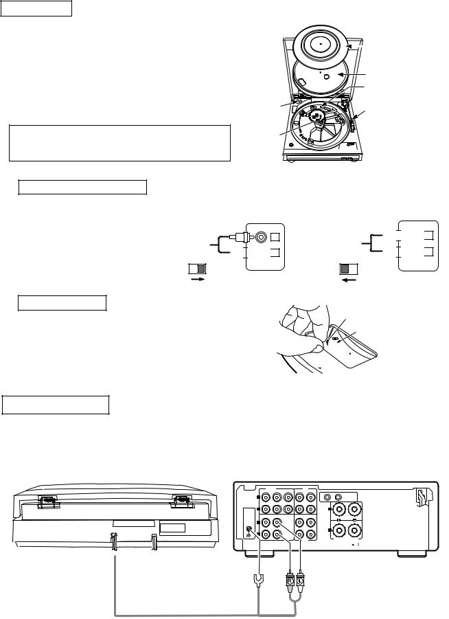
ASSEMBLY
1.Remove the main unit with the packing from the box and take off the packing.
2.Set the 45-rpm adaptor on the main unit as shown in the diagram.
3.Insert the turntable onto the center spindle.
4.Set the belt on the driving pulley. (The belt is wound on the turntable.)
5.Set the turntable sheet on the turntable.
6.Remove the tie securing the tonearm.
NOTE:
The turntable will not function if this tie is not removed.
|
Turntable sheet |
|
Turntable |
|
Equalizer Amplifier switch |
45-rpm adaptor |
Tonearm fixing tie |
|
|
Center spindle |
|
7.
8. Equalizer Amplifier switch
9. This unit has built-in RIAA
10. equalizer amplifier,so it can
11. be connected to an amplifier
12. without PHONO(turntable)
13. input jack. According to the
14. amplifier, set the EQUALIZER
15. AMPLIFIER SWITCH.
16.
Setting the belt
When the unit is connected to the PHONO(MM) jacks:
L


 R
R
PHONO
ON OFF
Grasp both sides of the tape and set the belt on the motor pulley. Once the belt is set properly, remove the tape.
Set the belt on the motor pulley properly as shown in the diagram.
When the unit is connected to the AUX jacks, etc:


 L
L


 R
R
AUX
ON OFF
Tape
Driving roller


 Belt
Belt
 Turntable
CONNECTIONS
1.Connect the left (white) and right (red) output cords respectively to your amplifier’s PHONO jacks etc .
2.Connect the ground wire to the amplifier’s signal ground terminal.
3.Plug the power cord into a wall outlet. (Or if the amplifier has power outlets, plug it in there, but before doing so, read the amplifier’s manual and check that the capacity is sufficient.)
|
INPUTS |
TAPE |
PB |
|
|
|
|
|
CD |
DVD/AUX AUX-2 |
MD |
2 |
|
|
|
|
L |
|
|
1 |
SYSTEM |
|
|
|
|
|
|
|
CONNECTOR |
||
SIGNAL |
R |
|
|
|
L |
|
|
GND |
TUNER |
PHONO |
TAPE |
MD |
|
|
|
|
|
|
|
||||
|
L |
|
|
|
|
|
|
|
|
|
|
|
R |
|
|
|
R |
|
|
|
|
|
|
|
|
|
|
REC |
|
SPEAKER SYSTEM |
|
|
|
|
|
SPEAKER IMPEDANCE |
|||
|
|
|
|
|
|
4 |
16 |
Ground wire |
Red |
White |
Output cord |
|
|
2
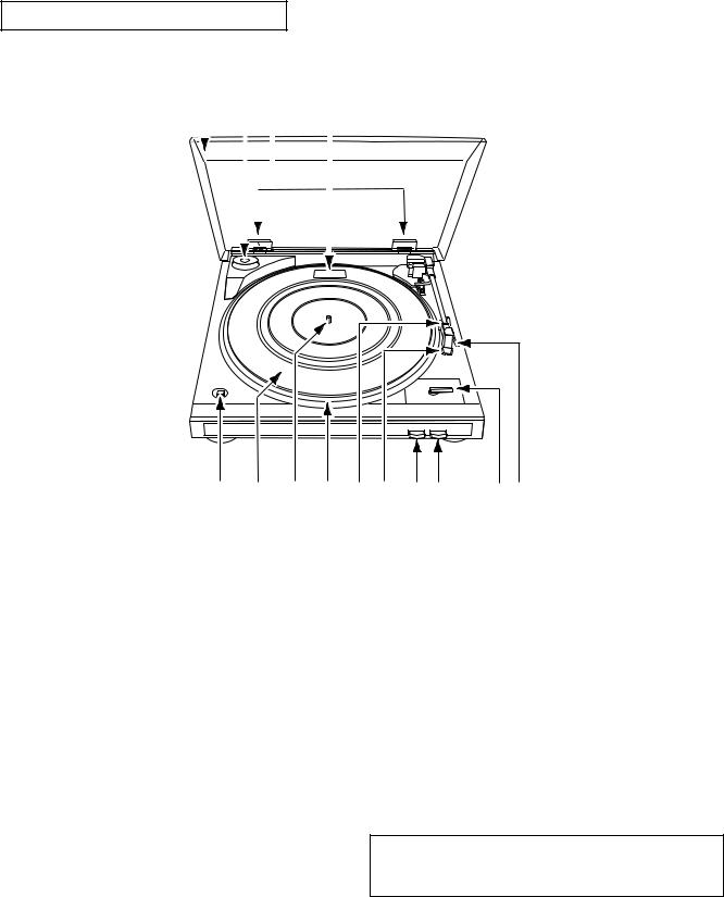
PART NAMES AND FUNCTIONS
1 |
2 |
3 |
4 |
|
|
|
|
||||
|
|
|
|
|
|
|
|
|
|
|
|
|
|
|
|
|
|
|
|
|
|
|
|
|
|
|
|
|
|
|
|
|
|
|
|
|
|
|
|
|
|
|
|
|
|
|
|
|
|
|
|
|
|
|
|
|
|
|
|
|
|
|
|
|
|
|
|
|
|
|
|
|
|
|
|
|
|
|
|
|
|
|
|
14 |
13 |
12 |
11 |
10 |
9 |
8 |
7 |
6 5 |
1Dust cover
245 rpm adaptor and holder
3Dust cover hinge
4Equalizer amplifier switch
5Finger lever
6Size Select Lever
Set according to the size of the record.
7STOP Button
Press to stop playback.
8START Button
Press to start playback.
9Cartridge
10Tone arm rest
Holds the tone arm.
11Platter
12Spindle
13Rubber mat
Place on the turntable.
14SPEED Select Button
Set according to the record speed. For 33 1/3 rpm: £
For 45 rpms: ¢
NOTE:
As this set is light, it may move when buttons or knobs are operated, so do not press too strongly.
3
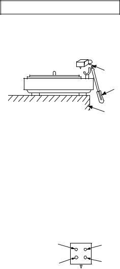
CARTRIDGE REPLACEMENT
(The cartridge forms a single body with the head shell. Use the following procedure to replace it.)
1.Remove the screw on the bottom of the head shell sa shown in the diagram.
Screw (philips) small
Screwdriver (philips) small
Desk, table, etc
2.Rotate the entire head shell gently in both directions.
The neck of the head shell is attached to the pipe arm.
Turn it gently until the shell comes loose.
3.Carefully remove the head shell.
(Be careful not to break the lead wire.)
4.Remove the tip of the lead wire from the carridge terminal.
5.Install the new cartridge (with head shell). The polarities are as shown on the diagram.
LH (white) |
Top |
RH (Red) |
|
LE ground wire (white side) |
RE ground wire (red side) |
Tip side (as seen from the rear of the cartridge)
6.Assemble by following the removal procedure in reverse order.
Use one drop of Cemedyne #3000 to atttach the neck of the head shell and the pipe arm.
4
Loading...