

Denon DN-D6000 Service Manual
For U.S.A., Canada, Europe,
U.K., Asia, China, Taiwan R.O.C.
& Korea model
SERVICE MANUAL
MODEL DN-D6000
DOUBLE CD PLAYER
Ver. 1
●
For purposes of improvement, specifications and
design are subject to change without notice.
●
Please use this service manual with referring to the
operating instructions without fail.
●
Some illustrations using in this service manual are
slightly different from the actual set.
注 意
サービスをおこなう前に、このサービスマニュアルを
必ずお読みください。本機は、火災、感電、けがなど
に対する安全性を確保するために、さまざまな配慮を
おこなっており、また法的には「電気用品安全法」に
もとづき、所定の許可を得て製造されております。
従ってサービスをおこなう際は、これらの安全性が維
持されるよう、このサービスマニュアルに記載されて
いる注意事項を必ずお守りください。
●
本機の仕様は性能改良のため、予告なく変更すること
があります。
●
補修用性能部品の保有期間は、製造打切後8年です。
●
修理の際は、必ず取扱説明書を参照の上、作業を行っ
てください。
●
本文中に使用しているイラストは、説明の都合上現物
と多少異なる場合があります。
TOKYO, JAPAN
X0216V.01 DE/CDM 0410

DN-D6000
SAFETY PRECAUTIONS
The following check should be performed for the continued protection of the customer and service technician.
LEAKAGE CURRENT CHECK
Before returning the unit to the customer, make sure you make either (1) a leakage current check or (2) a line to chassis
resistance check. If the leakage current exceeds 0.5 milliamps, or if the resistance from chassis to either side of the
power cord is less than 460 kohms, the unit is defective.
LASER RADIATION
Do not stare into beam or view directly with optical instruments, class 3A laser product.
500V
(1)
(2)
1M
(1)
(2)
2
DISASSEMBLY
(Follow the procedure below in reverse order when reassembling.)
Main Unit
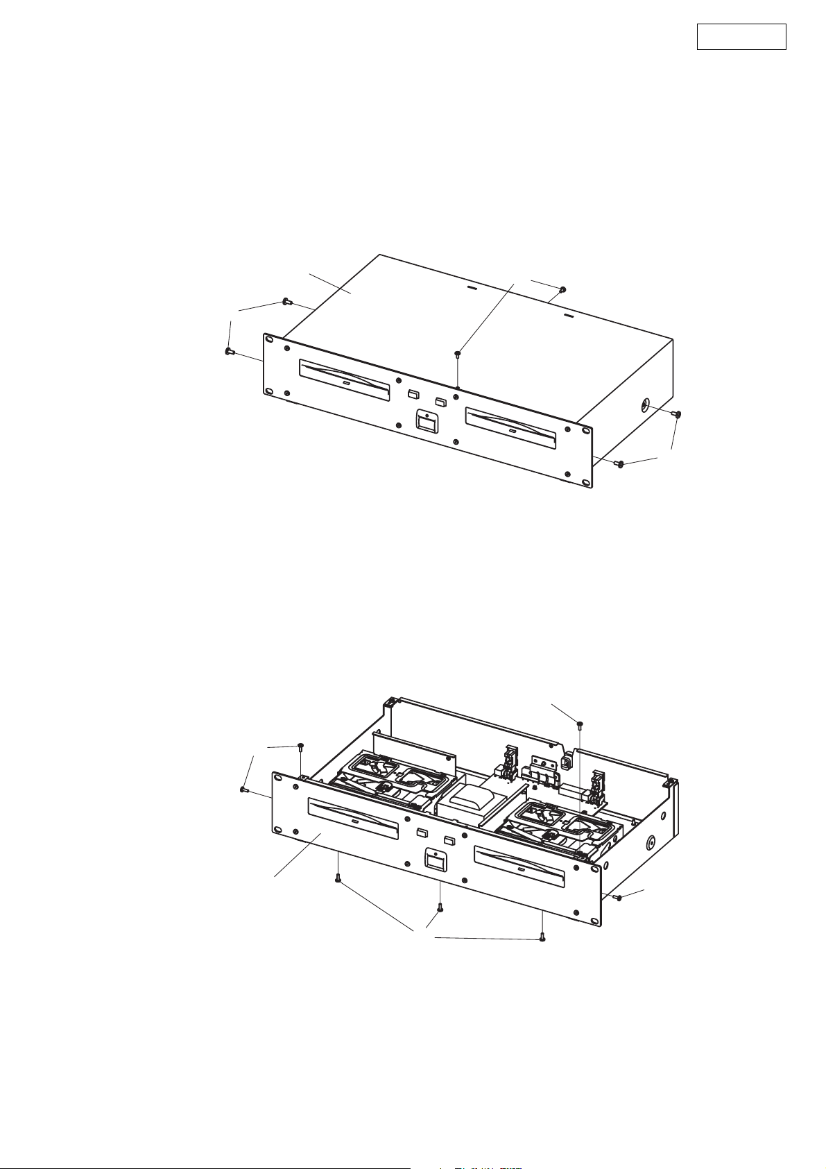
1. Top cover
(1) Remove 4 screws 56 and 2 screws 59.
(2) Detach Top Cover.
DN-D6000
Top cover
56
2. Front panel unit
(1) Remove 7 screws 59 and pull out Front panel unit.
59
56
59
Front panel unit
59
59
59
3

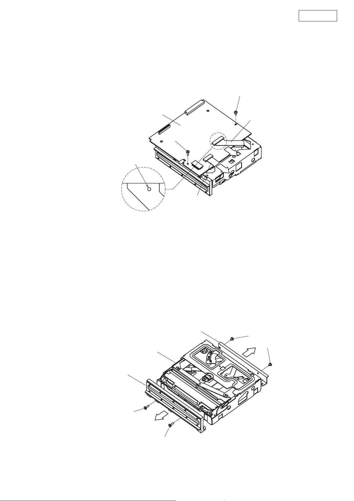
3. Mecha unit
(1) Remove 8 screws 59.
(2) Disconnect FFC cable.
(3) Remove 2 screws 51 and 2 screws 53.
(4) Detach Mecha unit.
Mecha unit
DN-D6000
Mecha unit
59
FFC cable
Mecha unit
59
CX302
59
59
CX301
FFC cable
51
Note:
z Do not pull out aslant to prevent Flat cable damage.
z Do not fail to pull AC cord from wall outlet before disconnect the Flat Cable.
If AC cord is remained plugged into wall outlet, power is kept supplied in the unit, which may cause danger.
53
4
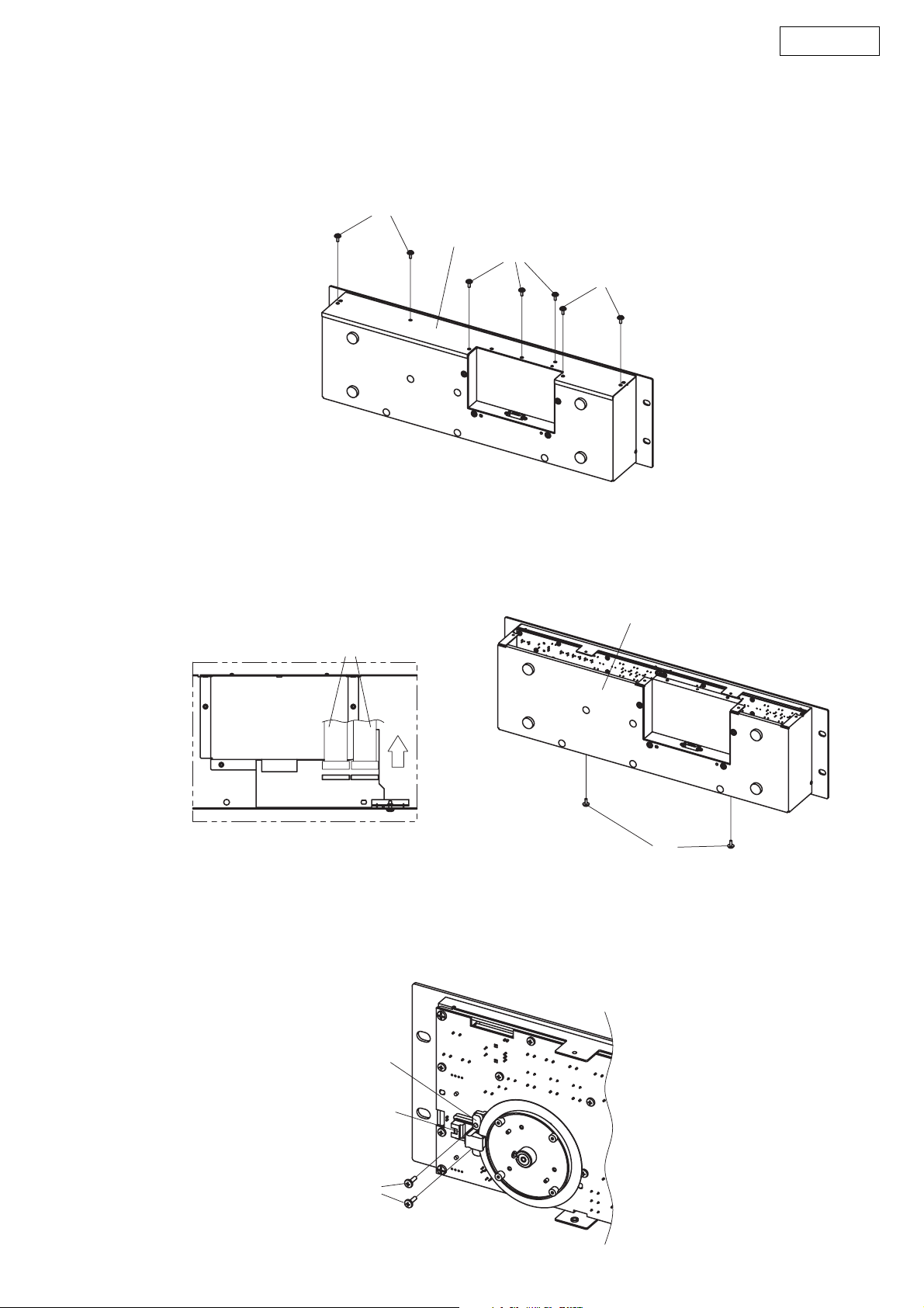
4. Main P.W.B.
(1) Short-circuit the short land above.
(2) Remove a screw 52 and a screw 54.
(3) Disconnect FFC cable and FPC cable.
(4) Detach Main P.W.B.
DN-D6000
52
Main Pwb
Short land for laser diode
Note:
z Do not pull out aslant to prevent FFC cable damage.
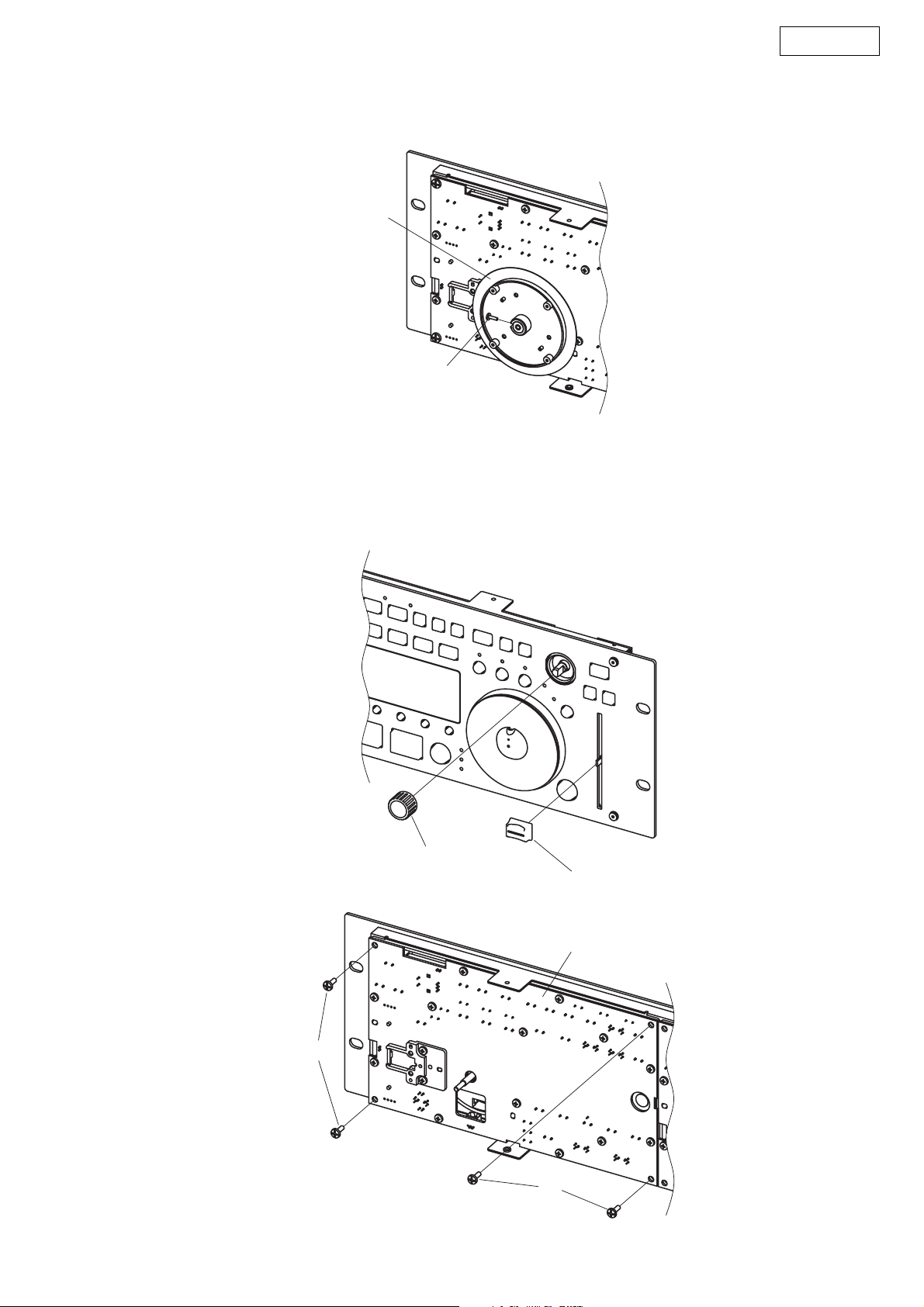
5. CD Mecha
(1) Remove 2 screws 51 and pull out Main Pwb Bracket.
(2) Remove 2 screws 53 and pull out Disc Guide.
FPC Cable
54
FFC Cable
Disc Guide
53
CD Mecha
53
Main Pwb Bracket
51
51
5
Remote Control Unit
1. Top cover
(1) Remove 7 screws 58.
(2) Detach Top cover.
DN-D6000
58
Top cover
58
58
2. Cover
(1) Disconnect Connector.
(2) Remove 2 screws 58 and pull out Cover.
Connector
CX122
3. Sensor unit
(1) Remove 2 screws 53 and pull out Sensor cover.
(2) Detach Sensor unit.
Cover
CX121
58
Sensor cover
Sensor unit
53
6
4. Wheel unit
(1) Remove a screw 51 and pull out Wheel unit.
Wheel unit
5. Inner Panel unit
(1) Pull out Knob (MARU) and Fader knob.
(2) Remove 4 screws 57 and pull out Inner panel unit.
DN-D6000
51
57
Knob (MARU)
Fader knob
Inner panel unit
57
7
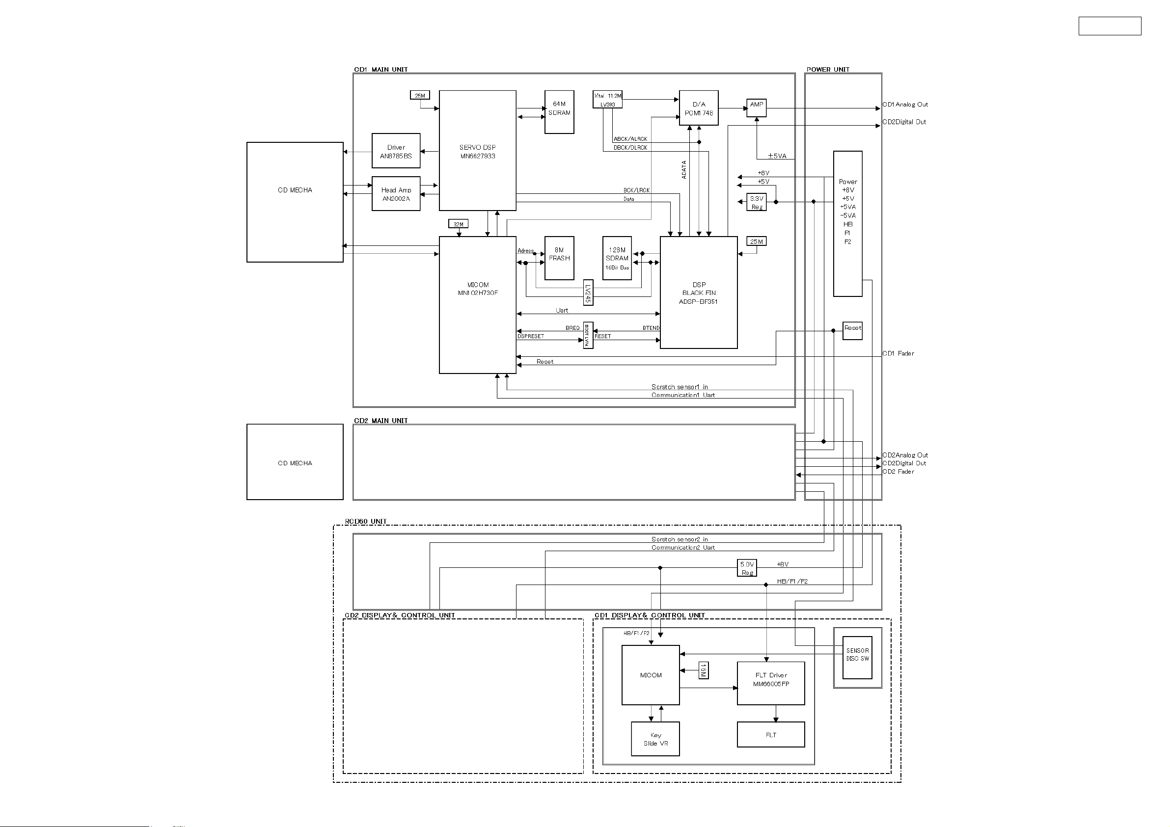
BLOCK DIAGRAM
DN-D6000
8
DN-D6000
CONFIRMING THE SERVO
What is Service Program
Service program is a special program intended for confirming servo functions etc.
This manual use both as DN-S1000 and DN-D6000
Required Measuring Implement
Reference disc (TCD784 or CO-74176)
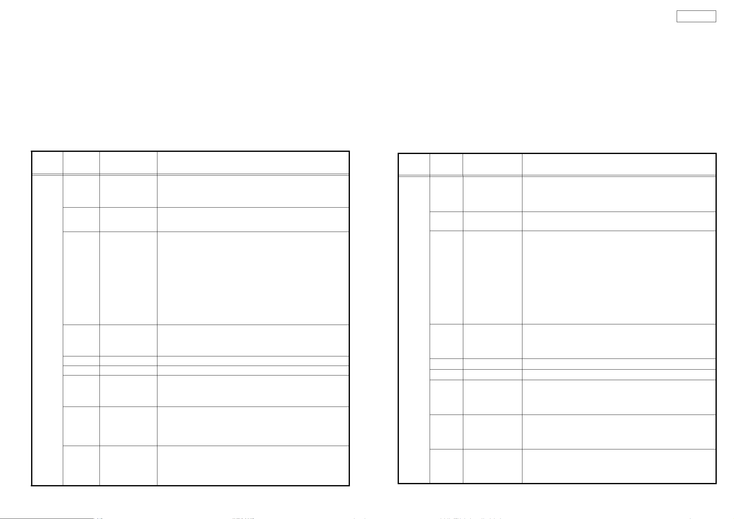
1. Contents of Service Program
Turn on the power while pressing both B button and the PARAMETER knob to set the service mode of DN-S1000. Turn on the power
while pressing both PARAMETER knob of CD1 and "LOOP B" button of CD2 to set the service mode of DN-D6000. The various
check items can be selected with the PARAMETER knob, the various test items can be selected with the A, B, SAMP and BEND
buttons. Press either the PARAMETER knob or PLAY/PAUSE button to start the check or test and display the result.
To eject the disc, press the DISC EJECT button.
To cancel the service mode, turn the power off.
PAR A M ET ER
knob
Process No.
(TRACK
Indication)
01
02
03
04 "Fo_Gain"
05 "Tr_Gain" Select the tracking gain. Default : 2. The operation is the same as for the Fo Gain.
06 "Block_Error" The block error rate is displayed.
07 "PU._Clean"
08
09
Function
(Character-display)
µcom Version check
(Version No.)
"TR_Signal"
"HF_Signal"
Automatic Servo
Adjustment call
(Servo Data)
Error Code Check
(Error Data)
Total Running Time
(Total Time)
Contents
A PARAMETER knob is pushed and a version is checked.
1. System µcom version No. : "Sys_XXXX"
2. DSP soft version No. : "Dsp_XXXX"
3. RC µcom version No. : "Rc_XXXX" (DN-D6000 only)
Press the PARAMETER knob to turn the tracking servo off.
When the tracking servo is off, press the PARAMETER knob to turn the tracking
servo on.
Press the PARAMETER knob to start automatic servo adjustment. When the
adjustment is completed, the adjustment data is displayed. The data can be
selected by turning the scratch disc.
1. Disc check, CD/CD-RW
2. Focus gain data
3. Focus balance data
4. Focus offset data
5. Tracking gain data
6. Tracking balance data
7. Tracking offset data
8. S curve maximum
9. S curve minimum
Select the focus gain. Default : 7. Select the data with the scratch disc, then press
the PARAMETER knob to enter it. The higher the value, the higher the gain, while
the lower the value, the lower the gain.
* Do not change this without instruction from engineering.
When the PARAMETER knob is pressed, the pickup moves towards the outer
edge of the disc. The pickup lens becomes visible through the slit in the CD mechanism plate. The lens can be cleaned using a cotton swab, etc.
(Perform this operation with the top panel/cover removed and the disc ejected.)
During normal operation, the error code for the error that occurred is displayed.
Turn the disc to select up to 10 sets of error data stored in the memory. (See the
error code table for a description of the error codes.)
Press the PARAMETER knob to set the error data clear mode. ("Err Clear?" is
・
displayed.) Press the PARAMETER knob again to clear all the error data.
The total operating time of the spindle motor is displayed. A total of 65,535 hours
can be counted, in units of hours.
NOTE: If the power is turned off after 59 minutes or less, that hour is not counted.
Press the PARAMETER knob to set the total time clear mode. ("Time Clear?" is
・
displayed.) Press the PARAMETER knob again to clear the total time.
サービスモード
サービスモードについて
サービスモードは、サーボ状態などを確認するための特別なプログラムです。
このマニュアルは DN-S1000、DN-D6000 兼用です。
確認に必要な測定器具
リファレンスディスク:TCD784、CO-74176
1. サービスプログラムの内容
DN-S1000 は B ボタンとパラメータノブを両方押しながら、電源を投入するとサービスモードになります。DN-D6000 は CD1 のパラメータノブと
CD2 の LOOP の B ボタンを押しながら電源を投入します。パラメータノブで各チェック項目が、A ボタン、B ボタン、SAMP ボタン、または
BEND ボタンで各テスト項目が選択できます。パラメータノブを押すか、PLAY/PAUSE ボタンを押すと各項目のチェック、テストを開始し、その結果
を表示します。
ディスクをイジェクトするには、DISCEJECT ボタンを押します。
サービスモードをキャンセルするには、電源を切ってください。
パラメータノブ
チェック項No.
( トラック番号)
01
02
マイコンバージョンチェツク
VersionNo
"TRSignal"
"HFSignal"
サーボ自動調整値
03
読み出し
(ServoData)
04 "FoGain"
05 "TrGain" トラッキングゲインを選択します。デフォルト -2.操作方法は FoGain と同じ。
06 "BlockError" ブロックエラーレートが表示されます。
07 "PU.Clean"
08
09
エラーコードチェック
(ErrorData)
トータルランニングタイム
(TotalTime)
機能
キャラクター表示
内容
パラメータノブを押して、バージョンをチェックします。
1.システムマイコンバージョン No.:"SysXXXX"
2.DSP ソフトバージョン No.:"DspXXXX"
3.RC マイコンバージョン No.:"RcXXXX"(DN-D6000 のみ )
パラメータノブを押すとトラッキングサーボを off します。
トラッキングサーボ off のとき、パラメータノブを押すとトラッキングサーボを on します。
パラメータノブを押すとサーボ自動調整を開始します。調整が終了すると、調整データ表示
します。データはスクラッチディスクを回すことで選択できます。
1.ディスクチェック、CD/CD-RW
2.フォーカスゲインデータ
3.フォーカスバランスデータ
4.フォーカスオフセットデータ
5.トラッキングゲインデータ
6.トラッキングバランスデータ
7.トラッキングオフセットデータ
8.S カーブ最大値
9.S カーブ最小値
フォーカスゲインを選択します。デフォルト -7。スクラッチディスクでデータを選択し、パラメータノブを押
すと確定されます。数値が大きくなるとゲインが高くなり、数値が小さくなるとゲイン
が低くなります。
*設計からの指示がない限り変更しないで下さい。
パラメータノブを押すとピックアップがディスク外周方向へ移動します。CD メカ板金の隙間から
ピックアップのレンズが見えるようになります。綿棒等でレンズをクリーニングすることができ
ます。
( トップパネル / カバーを外し、ディスクをイジェクトした状態で実施下さい)
通常動作時、発生したエラーのエラーコードが表示されます。ディスクを回すと、最大 10 個
まで、記憶されたエラーデータが選択できます。( エラーコードはエラーコード表を参照下さい。)
・パラメータノブを押すと、エラーデータ消去モードになります。(ErrClear?が表示されます )
再度、パラメータノブを押すと、全てのエラーデータが消去されます。
スピンドルモータのトータル動作時間を表示します。1 時間単位で 65535 時間まで計測でき
ます。注意 )59 分以下で電源を切るとカウントされません。
・パラメータノブを押すと、トータル時間消去モードになります。(TimeClear?が表示されま
す ) 再度、パラメータノブを押すと、トータル時間が消去されます。
9
DN-D6000
CUE button FLT all light check performed while button pressed.
BEND+ button FLT all off check performed while button pressed.
BEND- button Disc eject status set while button pressed.
The disc loading/eject roller turns. The dirt can be cleaned off the roller by gently pressing a cotton swab with
propyl alcohol"
, against the roller.
(Perform this operation with the top panel/cover removed and the disc ejected.)
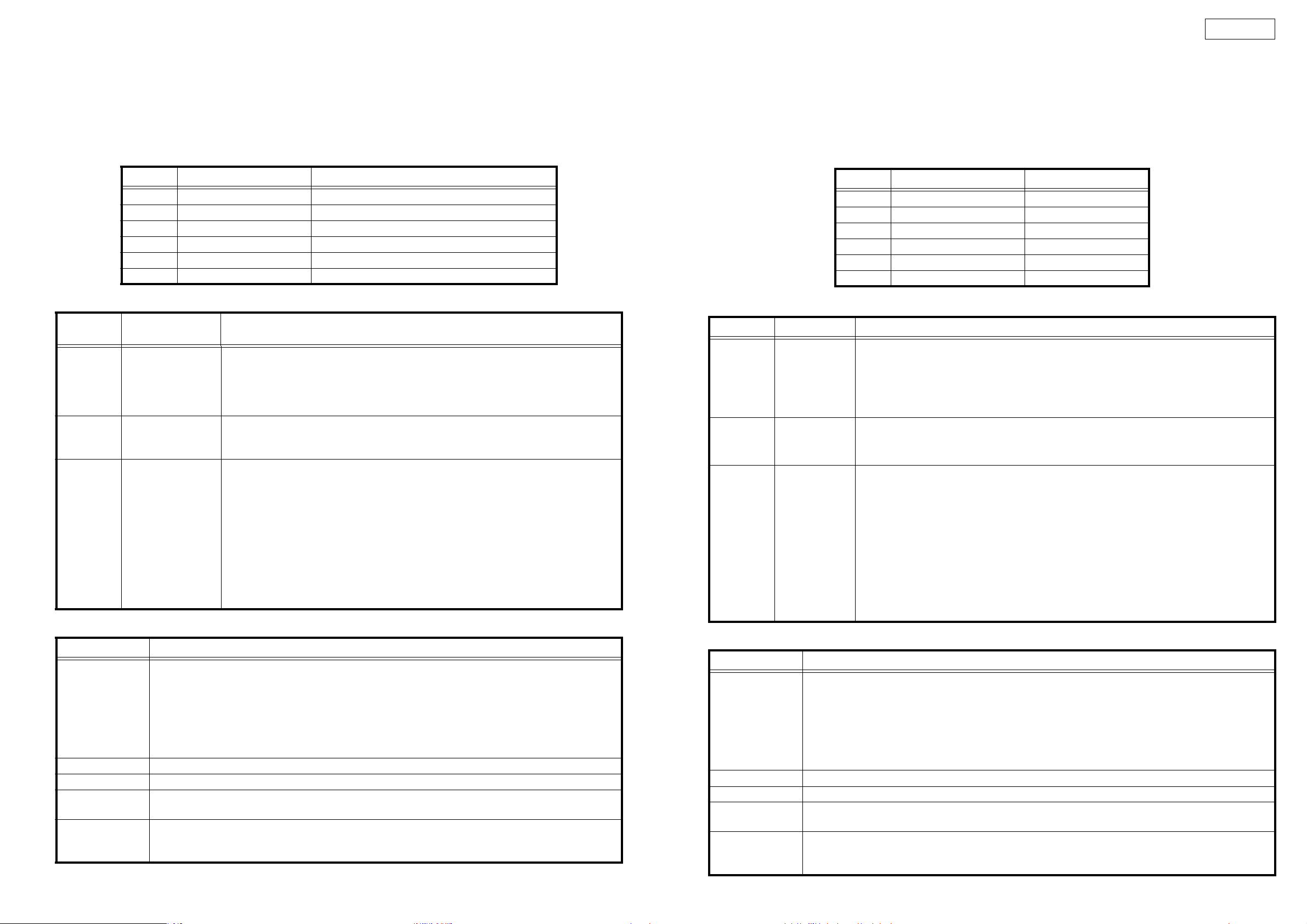
Servo automatic adjustment read-out value
Adjustment Item Adjustment Value indication at character portions.
1 Focus Gain 0408 ~ 3248
2 Focus Balance -50 ~ +50
3 Focus Offset -005 ~ +005
4 Tracking Gain 0392 ~ 1569
5 Tracking Balance -025 ~ +025
6 Tracking Offset -005 ~ +005
2. TEST MODE
A button
A2 button
SAMP button
Function
(Character-display)
Heat Run Test
H/R1 Normal
Chucking Test
H/R2 Tray
System check
Sys. Check
Press button A1, then press the PLAY/PAUSE button to start the test.
The disc is ejected, loaded and played repeatedly.
For discs containing 20 tracks or less, all the tracks are played.
For discs containing 21 tracks or more, only the first and last tracks on the disc are played.
If an error occurs, the error code is displayed and the stop mode is set.
Press button A2, then press the PLAY/PAUSE button to start the test.
The disc load/eject, servo input and TOC reading operations are performed repeatedly.
If an error occurs, the error code is displayed and the stop mode is set.
Press button EXIT/RELOOP, then press the PLAY/PAUSE button to start the system check.
Once the check is completed, the results are displayed.
1. The system µcom and DSP communications are checked.
2. Reading and writing SDRAM of DSP are checked.
3. Reading and writing SDRAM of servo DSP are checked.
4. Communications between the system µcom and servo DSP are checked.
5. The CD drive operation is checked. (Inner edge switch detection is performed.)
6. The CD drive operation is checked. (Disc detection is performed.)
Once all the checks are completed, the results are displayed on the character display. The
numbers of the checks in items 1 to 6 above that were OK are displayed. If one of the checks
was not OK, the number of that item is not displayed.
Contents
3. Error Code Table (Appears only at Heat Run and Chucking Test function)
Error Code Contents
Automatic Adjustment Error
E1 00
E1 01
E1 03
E1 04
E1 05
E1 06
E2 02 Servo down during automatic Adjustment
E3 00 Unable to read TOC
E4 00
E4 01
E5 00
E5 01
E5 02
Unable to detect disk
Unable to adjust tracking offset
Unable to adjust focus fine gain
Unable to actuate focus
Unable to actuate tracking
Unable to adjust tracking fine gain
Unable to close the disc holder in the regular time
Unable to open the disc holder in the regular time
The inner SW dose not turn on
Slider error
The inner SW dose not turn off
"Iso-
CUEボタン ボタンを押している間、FLT の全点灯チェックを行います。
BEND+ ボタン ボタンを押している間、FLT の全消灯チェックを行います。
BEND- ボタン ボタンを押している間、ディスクをイジェクト状態にします。
ディスクローディング / イジェクト用のローラーが回転しますので、イソプロピルアルコールを付けた綿棒をローラーに軽く押し当てることに
より、ローラーの汚れを落とすことができます。
( トップパネル / カバーを外し、ディスクをイジェクトした状態で実施下さい )
サーボ自動調整読み出し値
サーボ調整項目 調整 OK 範囲
1 フォーカスゲイン 0408 〜 3248
2 フォーカスバランス -50 〜 +50
3 フォーカスオフセット -005 〜 +005
4 トラッキングゲイン 0392 〜 1569
5 トラッキングバランス -025 〜 +025
6 トラッキングオフセット -005 〜 +005
2. テストモード
機能キャラクター表示 内容
A1 ボタンを押し、PLAY/PAUSE ボタンを押すとテストを開始します。
ディスクの出し入れと、再生を繰り返します。
20 トラック以下のディスクのときは、全てのトラックを再生します。
21 トラック以上のディスクのときは、ディスク先頭トラックと最終トラックのみ再生します。エラーが発生すると、エラーコード
Aボタン
ヒートランテスト
H/R1Normal
を表示して停止します。
A2 ボタンを押し、PLAY/PAUSE ボタンを押すとテストを開始します。
ディスクの出し入れと、サーボ投入、TOC の読み込みを繰り返します。
エラーが発生すると、エラーコードを表示して停止します。
A2 ボタン
チャッキングテスト
H/R2Load
EXIT/RELOOP ボタンを押し、PLAY/PAUSE ボタンを押すとシステムチェックを開始し、チェック終了後、その結果を表
示します。
1.システムマイコンと DSP の通信チェツクを行います。
2.DSP の SDRAM のリード / ライトチェツクを行います。
SAMP ボタン
システムチェック
Sys.Check
3.サーボ DSP の SDRAM のリード / ライトチェツクを行います。
4.システムマイコンとサーボ DSP の通信チェツクを行います。
5.CD ドライブの動作チェックを行います。( 内周 SW の検出をおこないます。)
6.CD ドライブの動作チェックを行います。( ディスク検出をおこないます。)
全てのチェックが終了すると、キャラクター表示に結果を表示します。1 〜 6 項目のチェックが OK の時は、OK になっ
た項目の番号が表示されます。NG の項目が合った場合、NG になった項目の番号が表示されません。
3. エラーコードテーブル ( ヒートランテスト、及び、チャッキングテストのとき表示されます )
エラーコード 内容
サーボ自動調整エラー
E100
E101
E103
E104
E105
E106
E202 サーボ自動調整中サーボが外れた。
E300 TOC が規定時間内に読めない。
E400
E401
E500
E501
E502
ディスクが検出できない。
トラッキングオフセットが調整できない。
フォーカスゲインが調整できない。
フォーカスサーボが入らない。
トラッキングサーボが入らない。
トラッキングゲインが調整できない。
ディスクが規定時間内にローディングできない。
ディスクが規定時間内にイジェクトできない。
内周 SWON しない
スライドエラー
内周 SWOFF しない
10
DN-D6000
Error Indication
TR MIN SEC FRAM CHARACTER
displays the track No. in
which error occurred.
Displays the time at which error occurred.
H
****
E
****
Operation count
Error code
4. µcom update
With the DN-S1000 and DN-D6000, the system µcom and DSP can be updated from a disc.
(1) Creating the update disc
Use the procedure described below to create the disc for updating the system microprocessor and DSP.
① Store the update file on a CD-R or CD-RW disc in ISO9660 Mode 1 format, then finalize the disc.
・Write the distributed update files using the "DISC AT ONCE" CD writing software and finalize.
・Do not record any other software or data on the disc containing the update software.
・Do not change the file names - use the file names as distributed.
(2) Updating the system µcom and DSP
① Turn on the power and load the disc created in (1) above.
When the update disc is detected, "Version Up" is displayed. And "xxxx → yyyyy" and "Push Play!" are displayed by turns.
xxxx : Old Version No., yyyy : New Version No.
② Press the PLAY/PAUSE button. "NowLoading" is displayed and the updating procedure starts.
As updating proceeds, the playback position indicator lights in order from left to right.
NOTE: In some extremely rare cases, the updating procedure is not completed. If the updating procedure has not finished after
three minutes, there could be a problem. Turn off the power and repeat the operation from step (2) ① .
Depending on the problem that occurred, it may happen that no other operations can be performed. If this happens, GU-
3607 IC102 must be replaced. Software must be pre-recorded on the IC102. (When ordering the IC102, order the more
recent system microprocessor version number (GEN number).)
③ When updating is completed, "Complete!" is displayed and the disc is ejected.
* For DN-D6000, this operation must be performed for both CD1 and CD2.
エラー表示
トラック 分 秒 フレーム キャラクター
エラーが発生したトラック番号 エラーが発生した時間 (A タイム ) H ****動作回数
E ****エラーコード
4. マイコンアップデート
DN-S1000、DN-D6000 は、ディスクから、システムマイコン、DSP のアップデートを行うことができます。
(1) アップデートディスクの作成
システムマイコン、DSP のアップデート用ディスクディスクを下記に従い作成する。
① アップデート用のファイルを、CD-R、又は CD-RW ディスクに ISO9660,MODE1 のフォーマットで記録し、ファイナライズする。
・配布されたアップデートファイルを、CD ライティングソフトで DISCATONCE で書き込みしファイナライズする。
・アップデート用ソフト以外のソフトやデータを同一ディスク内に記録しないこと。
・ファイル名は、配布されたときのファイル名をそのまま使用すること。
(2) システムマイコン、DSP のアップデート
① 電源を投入し、(1) で作成したディスクをローディングします
アップデート用ディスクが検出されると、"VersionUp" と表示し、"xxxx → yyyy"、"PushPlay!" の交互表示になります。
xxxx:旧バージョン No.、yyyy:新バージョン No.
② PLAY/PAUSE ボタンを押すと、"NowLoading" を表示しアップデートを開始します。
アップデートの進行に合わせ、再生位置表示が左から右へ順に点灯します。
注意 ) 大変希ではありますが、アップデート中に、アップデート未終了の異常状態が発生することがあります。アップデートを開始し3分
を経過しても終了しない場合も、異常が発生したと考えられますので、電源を切って、再度、(2) ①から同一の操作を
行って下さい。
発生した異常状況により、以後の全ての動作が出来なくなることがあります。その場合、GU-3607IC102 の交換が必要
になります。IC102 は、予め、ソフトウエアを書き込みする必要があります。(IC102 を発注の際は、最新のシステム
マイコンバージョン No(GENNo) で発注願います。)
③ アップデートが終了すると、"Complete!" を表示しディスクがイジェクトされます。
* DN-D6000 は、CD1、CD2 個々に実施する必要があります。
11
SEMICONDUCTORS
Only major semiconductors are shown, general semiconductors etc. are omitted to list.
主な半導体を記載しています。汎用の半導体は記載を省略しています。
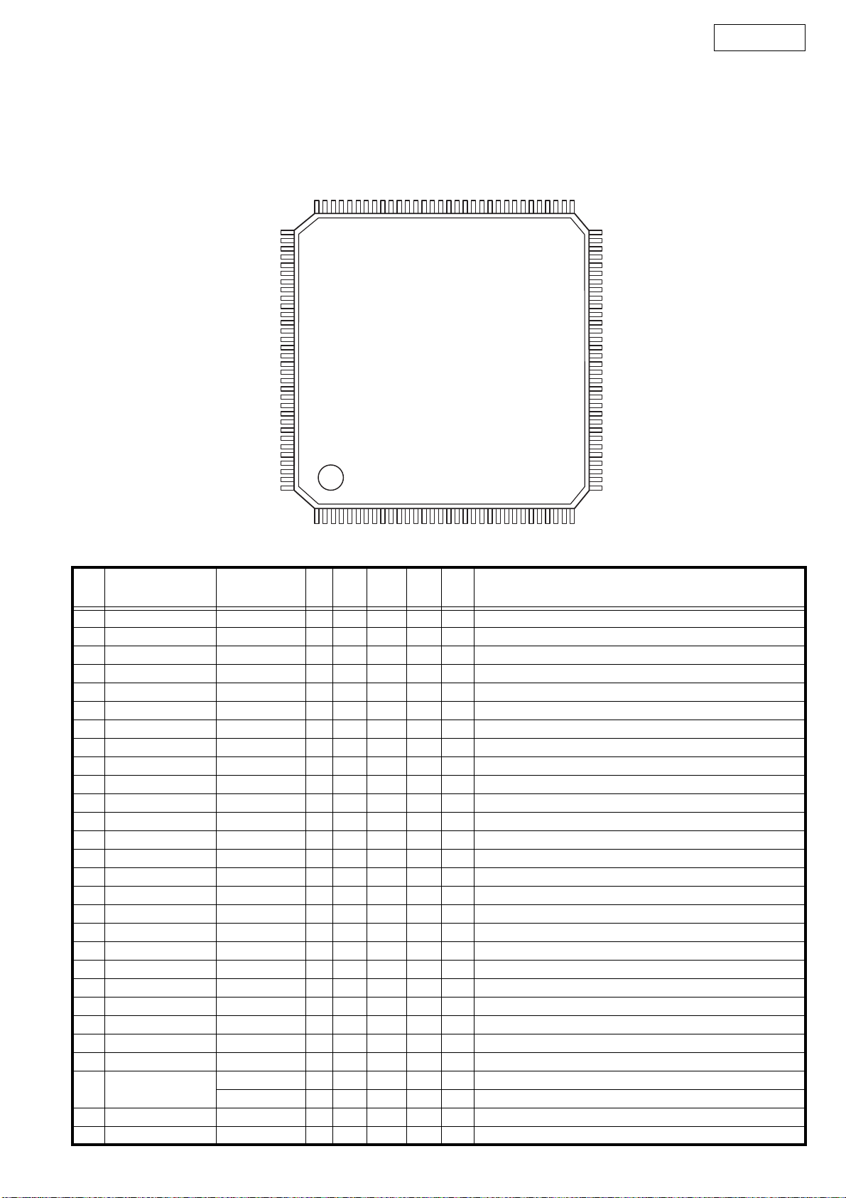
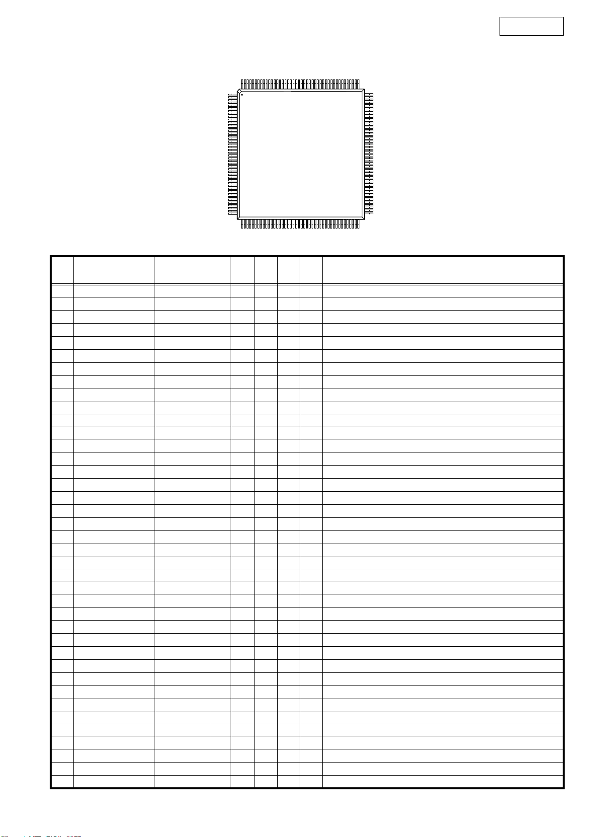
1. IC’s
MN102H730F (IC101)
96 65
97 64
TOP VIEW
DN-D6000
128 33
1
32
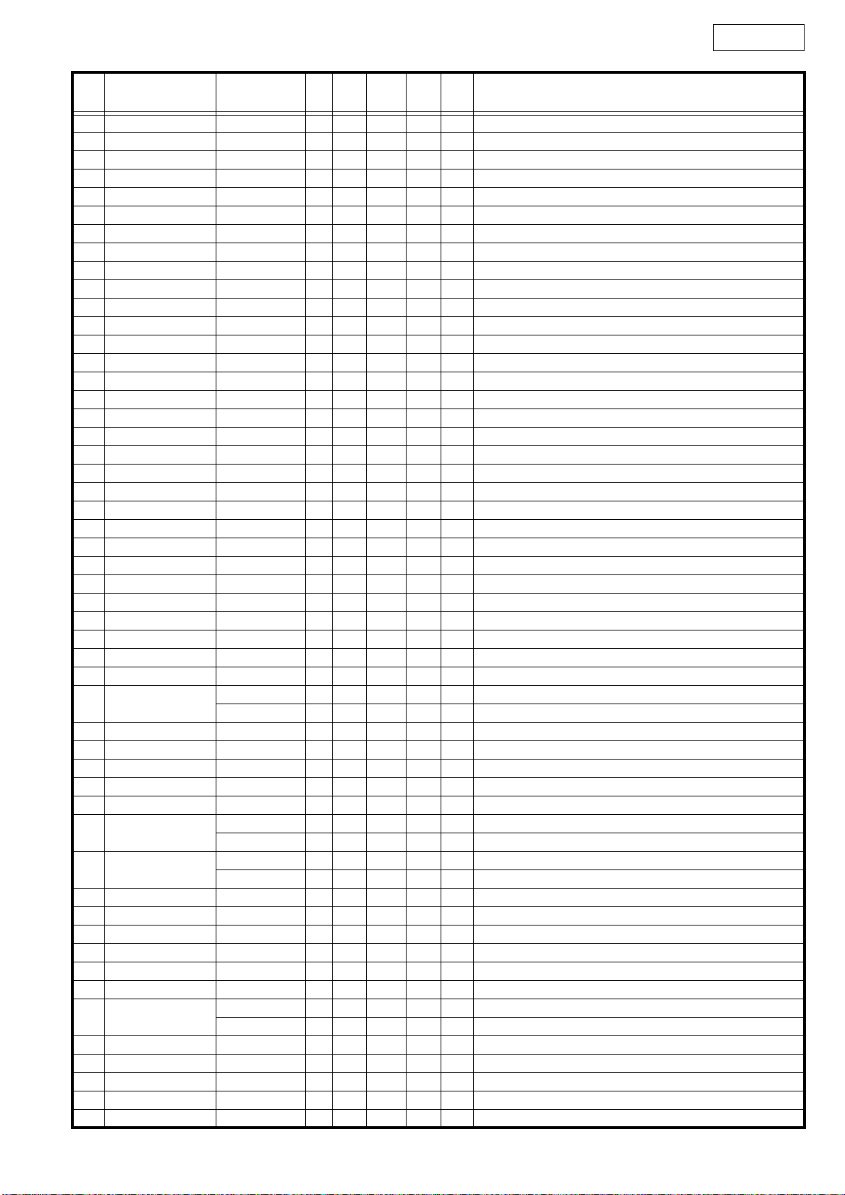
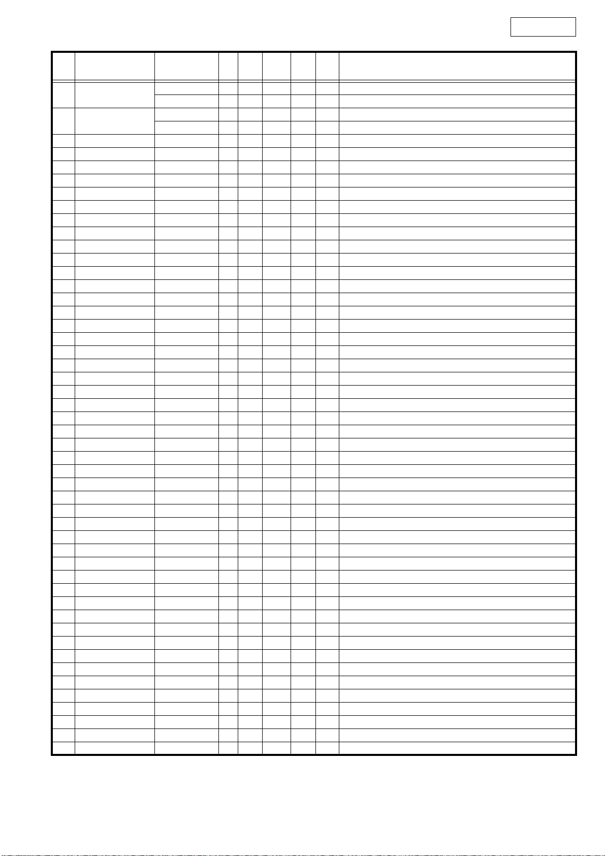
MN102H730F Terminal Function
Pin
No.
1 CS0_ CS0_ O - Pu - - Ext. memory chip select 0 (Frash ROM CS)
2 CS1_ CS1_ O - - - - Not used
3 D00 DQ0 I/O - - - - Ext. memory data I/O 0, DSP interface 0
4 D01 DQ1 I/O - - - - Ext. memory data I/O 1, DSP interface 1
5 D02 DQ2 I/O - - - - Ext. memory data I/O 2, DSP interface 2
6 D03 DQ3 I/O - - - - Ext. memory data I/O 3, DSP interface 3
7 VDD VDD - - - - - Power (+3.3V)
8 VSS VSS - - - - - GND
9 D04 DQ4 I/O - - - - Ext. memory data I/O 4, DSP interface 4
10 D05 DQ5 I/O - - - - Ext. memory data I/O 5, DSP interface 5
11 D06 DQ6 I/O - - - - Ext. memory data I/O 6, DSP interface 6
12 D07 DQ7 I/O - - - - Ext. memory data I/O 7, DSP interface 7
13 D08 DQ8 I/O - - - - Ext. memory data I/O 8, DSP interface 8
14 D09 DQ9 I/O - - - - Ext. memory data I/O 9, DSP interface 9
15 D10 DQ10 I/O - - - - Ext. memory data I/O 10, DSP interface 10
16 PD0,DMAACK1_ DLED O - Pu H - Disc LED
17 PD1,DMAREQ1_ DSPF3 O - - L - Flag 3 for DSP (RESERVE)
18 D11 DQ11 I/O - - - - Ext. memory data I/O 11, DSP interface 11
19 D12 DQ12 I/O - - - - Ext. memory data I/O 12, DSP interface 12
20 D13 DQ13 I/O - - - - Ext. memory data I/O 13, DSP interface 13
21 D14 DQ14 I/O - - - - Ext. memory data I/O 14, DSP interface 14
22 D15 DQ15 I/O - - - - Ext. memory data I/O 15, DSP interface 15
23 WORD WORD I - - Data bus width select (H: 16bit), GND fixed
24 VDD VDD - - - - - Power (+3.3V)
25 MODE MODE I - - L L Processor mode, GND fixed
26 PC3
27 XI XI I - - - - Oscillation input
28 XO XO O - - - - Oscillation output
Pin Name Simbol I/O DET Ext Ini Res Function
MODEL I - Pu L - RESERVE
MODEL I - Pd L - RESERVE
12
DN-D6000
Pin
No.
29 VDD VDD - - - - - Power (+3.3V)
30 OSCI OSCI I - - - - Oscillation input, 32.0MHz
31 OSCO OSCO O - - - - Oscillation output
32 VSS VSS - - - - - GND
33 P57,BOSC RESERVE O - - L - TP
34 PC5,NMI_ NMI I - - - - Connect to Power
35 RST_ RST_ I - - - - µcom reset
36 PC0 _MUTE O - Pd L L Mute signal (L: Mute)
37 P76 RESERVE O - - L - TP
38 P60,IRQ0 DTIME I - Pu H H X2: Clock for playback interrupt input / X1: LRCK
39 P61,IRQ1 BLKCK I - iPu - - Sub cord clock interrupt
40 P62,IRQ2,TM10IOA LOAD O - - Hi-Z - Disc roading, eject signal (PWM output)
41 P63,IRQ3,TM10IOB DQSY I - iPu - - CD-TEXT DQSY interrupt
42 P64,IRQ4 DTIMES I - Pu H H X2: Sampler clock for playback interrupt input / X1:
43 P65,IRQ5,TM12IOA DISCA I - - - - Disc for scratch pulse A count input
44 P66,IRQ6 DISCDIR I - (Pu) H H Scratch disc detect round direction interrupt input
45 P67,IRQ7 DISCINT I - (Pu) H H Disc round start interrupt input
46 P70,TM13IOB DISCPA I - (Pu) H H Pulse width for scratch disc gauge input
47 P71 ML O - iPu Hi-Z - D/A interface scratch
48 PD2,DMAACK0_ CHGOFT O - Pu L H Off-track signal (Transistor drive)
49 PD3,TM3IO DISCPA_ I - - - - Disc for scratch pulse A reverse phase count input
50 VDD VDD - - - - - Power (+3.3V)
51 P77 RESERVE O - - L - TP
52 P72,TM14IOB DISCPB I - - - - Disc for scratch pulse B count input
53 P73 _NRES O - Pd L L IC reset signal
54 P74 MLD O - - H - Servo DSP interface latch
55 P75,TM12IOB DCLK I - - - - Clock input for pulse width gauge for disc (5.6MHz)
56 PA0,SBI0 STAT I - iPu - - Servo DSP interface receive (clock sync)
57 PA1,SBO0 MDAT O - - H - Servo DSP interface send (clock sync)
58 PA2,SBT0 MCLK O - - H - Servo DSP interface clock (clock sync)
59 PA3,SBI1 RXDCD I - Pu - - Mecha. between interface receive (UART)
60 PA4,SBO1
61 PA5,SBT1 _DSTBY O - Pd L L Driver standby signal L: standby
62 PB0,SBI2 DSPTXD(RXD) I - Pu - - DSP interface receive (UART)
63 PB1,SBO2 DSPRXD(TXD) O - Pu H H DSP interface send (UART)
64 PB2,SBT2 _FLCS O - Pu H H DNS1000: FLT driver enable signal
65 PB3,SBI3 RXDRC I - - - - DND6000: RCD 60 interface receive (UART)
66 PB4,SBO3
67 PB5,SBT3
68 VDD VDD - - - - - Power (+3.3V)
69 VSS VSS - - - - - GND
70 AVSS AVSS - - - - - Analog ref. GND for A/D conversion, GND
71 Vref- Vref- - - - - - Analog ref. V for A/D conversion, GND
72 P80 _FLRES O - Pd L L DNS1000: FLT driver (M66005A) reset signal
73 P81 CSKSEL O - Pd H L L: Servo DSP D/A clock select
74 P82
75 P83 SEL_A O - - L - DNS1000: Key scan output select signal A
76 P84 SEL_B O - - L - DNS1000: Key scan output select signal B
77 P85 SEL_C O - - L - DNS1000: Key scan output select signal C
78 P86,AD06 PITCH I - - - - DNS1000: Slid VR for pitch data input
79 P87,AD07 PITCHC I - - - - DNS1000: Slid VR for pitch center value data input
Pin Name Simbol I/O DET Ext Ini Res Function
LEDCLK1 O - Pu H H DNS1000: LED driver (BU2090) clock 1 for data send
TXDCD O - Pu H - DND6000: Mecha. between interface receive (UART)
PDATA O - Pu H -
TXDRC O - Pu H - DND6000: RCD interface send (UART)
FLCLK O - - H -
RESERVE O - - H - DND6000: RESERVE
LEDCLK2 O - Pu H H DNS1000: LED driver (BU2090) clock 2 for data send
RESERVE I - Pu - - DND6000: RESERVE (connect to RXDCD)
DNS1000: FLT driver (M66005A) data, LED driver data (clock sync)
DNS1000: FLT driver (M66005A) clock for data send (clock sync)
13
DN-D6000
Pin
No.
80 PD4
81 PD5
82 P90 KIN2 I - Pu - H DNS1000: Key scan input signal 2
83 P91 KIN3 I - Pu - H DNS1000: Key scan input signal 3
84 P92 _LSSW I - iPu - - Disc input detect SW L: Disc in
85 P93 _PISW I - iPu - - Inner switch L: Switch ON
86 Vref+ Vref+ - - - - - Analog ref. V for A/D conversion, +3.3V
87 AVDD AVDD - - - - - Power (+3.3V)
88 P94 DSENS I - iPu - - Disc sensor 12/8 cm disc detect L: 12cm disc
89 P95 _CSW I - iPu - - Loading switch L: Switch ON
90 P96,DAC2 DSPF0 O - - L - Flag 0 for DSP (RESERVE)
91 P97,DAC3 _DSPRES O - Pd L L DSP reset signal L: RESET
92 PC6,BREQ_ _BREQ I - Pu - H Bus request signal
93 PC7,BRACK_ _BRACK O - Pu H H Bus request accept signal
94 WEL_ WE_ O - Pu - H Ext. memory write enable (Lower 8 bit)
95 P51 _BOOT O - Pu H H DSP boot start signal L: START
96 RE_ RE_ O - Pu - H Ext. memory read enable
97 CS2_ CS2_ O - - - - Ext. memory chip select 2 (Not used)
98 VDD VDD - - - - - Power (+3.3V)
99 VSS VSS - - - - - GND
100 P54,BSTRE FPLAY I - Pu H H Fader start PLAY input
101 P55,WR_ FCUE I - Pu H H Fader start CUE input
102 CS3_ CS3_ O - - - - Not used
103 A00 A00 O - - - - Ext. memory address 0 (16 bit bus select : not used)
104 A01 A01 O - - - - Ext. memory address 1 (16 bit bus select : not used)
105 A02 A02 O - - - - Ext. memory address 2 (16 bit bus select : not used)
106 A03 A03 O - - - - Ext. memory address 3 (16 bit bus select : not used)
107 A04 A04 O - - - - Ext. memory address 4 (16 bit bus select : not used)
108 A05 A05 O - - - - Ext. memory address 5 (16 bit bus select : not used)
109 A06 A06 O - - - - Ext. memory address 6 (16 bit bus select : not used)
110 A07 A07 O - - - - Ext. memory address 7 (16 bit bus select : not used)
111 A08 A08 O - - - - Ext. memory address 8 (16 bit bus select : not used)
112 PD6 DSPF1 O - - L - Flag 1 for DSP (RESERVE)
113 PD7,TM7IO DISCPB_ I - iPu - - Disc for scratch pulse B reverse phase count input
114 A09 A09 O - - - - Ext. memory address 9 (16 bit bus select : not used)
115 A10 A10 O - - - - Ext. memory address 10 (16 bit bus select : not used)
116 A11 A11 O - - - - Ext. memory address 11 (16 bit bus select : not used)
117 A12 A12 O - - - - Ext. memory address 12 (16 bit bus select : not used)
118 A13 A13 O - - - - Ext. memory address 13 (16 bit bus select : not used)
119 VDD VDD - - - - - Power (+3.3V)
120 PC4 DSPF2 O - - L - Flag 1 for DSP (RESERVE)
121 A14 A14 O - - - - Ext. memory address 14 (16 bit bus select : not used)
122 A15 A15 O - - - - Ext. memory address 15 (16 bit bus select : not used)
123 A16 A16 O - - - - Ext. memory address 16 (16 bit bus select : not used)
124 A17 A17 O - - - - Ext. memory address 17 (16 bit bus select : not used)
125 A18 A18 O - - - - Ext. memory address 18 (16 bit bus select : not used)
126 A19 A19 O - Pd - - Ext. memory address 19 (16 bit bus select : not used)
127 A20 A20 O - - - - Ext. memory address 20 (16 bit bus select : not used)
128 A21 A21 O - - - - Ext. memory address 21 (16 bit bus select : not used)
Pin Name Simbol I/O DET Ext Ini Res Function
KIN0 I - Pu - H DNS1000: Key scan input signal 0
EJECT I - Pu - H DND6000: Disc eject button input signal
KIN1 I - Pu - H DNS1000: Key scan input signal 1
CDSEL I - Pu - H DND6000: CD mecha. Select H: CD1, L: CD2
14
ADSP-BF531 (IC401)
DN-D6000
176
1
PIN 1
TOP VIEW
44
45
133
88
132
89
ADSP-BF531 Terminal Function
Pin
No.
1 GND GND - - - - - GND
2 GND GND - - - - - GND
3 GND GND - - - - - GND
4 VROUT2 O - - - - Ext. FET drive output 2
5 VROUT1 VROUT1 O - - - - Ext. FET drive output 1
6 VDDEXT VDDEXT I - - - - I/O power supply (+3.3V)
7 GND GND - - - - - GND
8 GND GND - - - - - GND
9 GND GND - - - - - GND
10 CLKIN CLKIN I - - - - Clock input
11 XTAL XTAL O - - - - Crystal/Oscillation terminal
12 VDDEXT VDDEXT I - - - - I/O power supply (+3.3V)
13 _RESET _RESET I - - - - Reset signal input
14 NMI NMI I - - - - Non-maskable interrupt
15GND GND -----GND
16 RTXO O - - - - RTC crystal/Oscillation output
17 RTXI I - - L L RTC crystal/Oscillation input
18 VDDRTC VDDRTC I - - - - Real time clock power supply (+3.3V)
19GND GND -----GND
20 VDDEXT VDDEXT I - - - - I/O power supply (+3.3V)
21 PPI_CLK I - - L L PPI clock
22 PPI0 O - - L - PPI data 0
23 PPI1 O - - L - PPI data 1
24 PPI2 O - - L - PPI data 2
25 VDDINT VDDINT I - - - - Core power supply (+1.2V)
26 PPI3 O - - L - PPI data 3
27 PF15 O - - L - Programmable flag 15
28 PF14 O - - L - Programmable flag 14
29 PF13 O - - L - Programmable flag 13
30GND GND -----GND
31 VDDEXT VDDEXT I - - - - I/O power supply (+3.3V)
32 PF12 O - - L - Programmable flag 12
33 PF11 O - - L - Programmable flag 11
34 PF10 O - - L - Programmable flag 10
35 PF9 O - - L - Programmable flag 9
36 PF8 O - - L - Programmable flag 8
37 PF7 O - - L - Programmable flag 7
38 PF6 DTIMES O - - L - Playback for SAMPLER clock output
39GND GND -----GND
Pin Name Symbol I/O DET Ext Ini Res Function
15

DN-D6000
Pin
No.
40GND GND -----GND
41GND GND -----GND
42GND GND -----GND
43GND GND -----GND
44GND GND -----GND
45 VDDEXT VDDEXT I - - - - I/O power supply (+3.3V)
46 PF5 DSPF3 O - - L - Programmable flag 5, Flag 3 to µcom (RESERVE)
47 PF4 DSPF2 O - - L - Programmable flag 4, Flag 2 to µcom (RESERVE)
48 PF3 DSPF1 O - - L - Programmable flag 3, Flag 1 to µcom (RESERVE)
49 PF2 DSPF0 O - - L - Programmable flag 2, Flag 0 to µcom (RESERVE)
50 PF1 DTIME O - - L - Programmable flag 1, Clock for playback output
51 PF0 BTEND O - Pd L L Programmable flag 0, All end : H
52 VDDINT VDDINT I - - - - Core power supply (+1.2V)
53 SCK O - - L - Master slave clock
54 MISO O - - L - Master in slave out
55 MOSI O - - L - Master out slave in
56GND GND -----GND
57 VDDEXT VDDEXT I - - - - I/O power supply (+3.3V)
58 DT1SEC O - - L - Playback data send 1
59 DT1PRI DDATA I - - - - Digital out data send 0 (serial port OUT 1)
60 TFS1 DLRCK I - IPu - H Digital out send frame sync (LRCK) signal (serial port OUT 1)
61 TSCLK1 DBCK I - - - - Digital out send frame sync (BCK) signal (serial port OUT 1)
62 DR1SEC I - - L L Playback data receive 1
63 DR1PRI I - - L L Playback data receive 0
64 RFS1 O - - L - Receive frame sync (LRCK) signal (serial port IN 1)
65 RSCLK1 O - - L - Receive frame sync (BCK) signal (serial port IN 1)
66 VDDINT VDDINT I - - - - Core power supply (+1.2V)
67 DT0SEC O - - L - Playback data send 1
68 DT0PRI ADATA I - - - - Analog playback data send 0 (serial port OUT 0)
69 TFS0 ALRCK I - IPu - H
70GND GND -----GND
71 VDDEXT VDDEXT I - - - - I/O power supply (+3.3V)
72 TSCLK0 ABCK I - - - - Analog playback send frame sync (BCK) signal (serial port OUT 0)
73 DR0SEC I - - L L Playback data receive 1
74 DR0PRI SRDATA I - - - - Playback data receive 0 (serial port IN 0)
75 RFS0 LRCK O - - - - Receive frame sync (LRCK) signal (serial port IN 0)
76 RSCLK0 BCLK I - IPu - H Receive frame sync (BCK) signal (serial port IN 0)
77 TMR2 O - - L - Timer 2
78 TMR1 O - - L - Timer 1
79 TMR0 O - - L - Timer 0
80 VDDINT VDDINT I - - - - Core power supply (+1.2V)
81 TX TX O - - H - UART send
82 RX RX I - Pu - H UART receive
83 _EMU _EMU O - - - - Emulation status
84 _TRST _TRST I - Pd - L Test reset (JTAG)
85 TMS TMS I - Pu - H Test mode select (JTAG)
86 TDI TDI I - Pu - H Test data input (JTAG)
87 TD0 TD0 O - - - - Test data output (JTAG)
88GND GND -----GND
89GND GND -----GND
90GND GND -----GND
91GND GND -----GND
92GND GND -----GND
93 VDDEXT VDDEXT I - - - - I/O power supply (+3.3V)
94 TCK TCK I - Pu - H Test clock (JTAG)
Pin Name Symbol I/O DET Ext Ini Res Function
Analog playback send frame sync (LRCK) signal (serial port OUT 0)
16
DN-D6000
Pin
No.
95 BMODE1 BMODE1 I - - - - Boot mode strap 1
96 BMODE0 BMODE0 I - - - - Boot mode strap 0
97GND GND -----GND
98 DATA15 D15 I/O - - - - Ext. bus data 15
99 DATA14 D14 I/O - - - - Ext. bus data 14
100 DATA13 D13 I/O - - - - Ext. bus data 13
101 DATA12 D12 I/O - - - - Ext. bus data 12
102 DATA11 D11 I/O - - - - Ext. bus data 11
103 DATA10 D10 I/O - - - - Ext. bus data 10
104 DATA9 D9 I/O - - - - Ext. bus data 9
105 DATA8 D8 I/O - - - - Ext. bus data 8
106 GND GND - - - - - GND
107 VDDEXT VDDEXT I - - - - I/O power supply (+3.3V)
108 DATA7 D7 I/O - - - - Ext. bus data 7
109 DATA6 D6 I/O - - - - Ext. bus data 6
110 DATA5 D5 I/O - - - - Ext. bus data 5
111 VDDINT VDDINT I - - - - Core power supply (+1.2V)
112 DATA4 D4 I/O - - - - Ext. bus data 4
113 DATA3 D3 I/O - - - - Ext. bus data 3
114 DATA2 D2 I/O - - - - Ext. bus data 2
115 DATA1 D1 I/O - - - - Ext. bus data 1
116 DATA0 D0 I/O - - - - Ext. bus data 0
117 GND GND - - - - - GND
118 VDDEXT VDDEXT I - - - - I/O power supply (+3.3V)
119 _BG O - - - - Bus grant signal
120 _BGH O - - - - Bus grant hang signal
121 ADDR19 BA1 I/O - - - - Ext. bus address 19
122 ADDR18 BA0/ADDR18 I/O - - - - Ext. bus address 18
123 ADDR17 ADDR17 I/O - - - - Ext. bus address 17
124 ADDR16 ADDR16 I/O - - - - Ext. bus address 16
125 ADDR15 ADDR15 I/O - - - - Ext. bus address 15
126 ADDR14 ADDR14 I/O - - - - Ext. bus address 14
127 ADDR13 ADDR13 I/O - - - - Ext. bus address 13
128 GND GND - - - - - GND
129 GND GND - - - - - GND
130 GND GND - - - - - GND
131 GND GND - - - - - GND
132 GND GND - - - - - GND
133 GND GND - - - - - GND
134 VDDEXT VDDEXT I - - - - I/O power supply (+3.3V)
135 ADDR12 ADDR12 I/O - - - - Ext. bus address 12
136 ADDR11 ADDR11 I/O - - - - Ext. bus address 11
137 ADDR10 ADDR10 I/O - - - - Ext. bus address 10 (SDRAM: connects SDA10)
138 ADDR9 ADDR9 I/O - - - - Ext. bus address 9
139 ADDR8 ADDR8 I/O - - - - Ext. bus address 8
140 ADDR7 ADDR7 I/O - - - - Ext. bus address 7
141 ADDR6 ADDR6 I/O - - - - Ext. bus address 6
142 ADDR5 ADDR5 I/O - - - - Ext. bus address 5
143 VDDINT VDDINT I - - - - Core power supply (+1.2V)
144 GND GND - - - - - GND
145 VDDEXT VDDEXT I - - - - I/O power supply (+3.3V)
146 ADDR4 ADDR4 I/O - - - - Ext. bus address 4
147 ADDR3 ADDR3 I/O - - - - Ext. bus address 3
148 ADDR2 ADDR2 I/O - - - - Ext. bus address 2
149 ADDR1 ADDR1 I/O - - - - Ext. bus address 1
Pin Name Symbol I/O DET Ext Ini Res Function
17
 Loading...