


Notice
The information in this guide is subject to change without notice.
Compaq Computer Corporation shall not be liable for technical or editorial errors or omissions contained herein; nor for incidental or consequential damages resulting from the furnishing, performance, or use of this material.
This guide contains information protected by copyright. No part of this guide may be photocopied or reproduced in any form without prior written consent from Compaq Computer Corporation.
Copyright 1994 Compaq Computer Corporation.
All rights reserved. Printed in the U.S.A.
Compaq, Deskpro, LTE, Contura
Registered U.S. Patent and Trademark Office.
LTE Elite, SmartStation, and MiniStation are trademarks of Compaq Computer Corporation.
Microsoft and MS-DOS are registered trademarks of Microsoft Corporation. Windows is a trademark of Microsoft Corporation.
The software described in this guide is furnished under a license agreement or nondisclosure agreement. The software may be used or copied only in accordance with the terms of the agreement.
Product names mentioned herein may be trademarks and/or registered trademarks of their respective companies.
MAINTENANCE AND SERVICE GUIDE
COMPAQ LTE ELITE FAMILY OF PERSONAL COMPUTERS
COMPAQ SMARTSTATION
First Edition (March 1994)
Part Number 194061-001

Preface
USING THIS GUIDE
This Maintenance And Service Guide is a troubleshooting reference for servicing the Compaq LTE Elite Family of Personal Computers, the Compaq SmartStation, the Compaq MiniStation/EN, and the Compaq MiniStation/TR.
The guide is organized into the following parts:
o Part 1: Compaq LTE Elite Computer (Chapters 1 through 5)
o Part 2: Compaq SmartStation (Chapters 6 through 10)
o Appendices
Compaq Computer Corporation reserves the right to make changes to the Compaq LTE Elite Family of Personal Computers and its options without notice.
SYMBOLS AND CONVENTIONS
The following format conventions distinguish elements of the text throughout this guide:
o When keys must be pressed at the same time, the action is represented by the key names and the plus (+) symbol. For example, Ctrl+Alt+Delete.
o The names of files are presented in uppercase, as shown here: FILENAME.
o The names of commands or directories are presented in uppercase type as shown here: COMMAND or DIRECTORY. Commands that are to be entered at the system prompt are shown on a separate line.
o When you are asked to type something without pressing the Enter key, you are directed to "type" the information.
o When you need to type information and press the Enter key, you are directed to "enter" the information.
The following words and symbols mark special messages throughout this guide:
>>>>>>>>>>>>>>>>>>>>>>>>>>>>>>>>> WARNING <<<<<<<<<<<<<<<<<<<<<<<<<<<<<<<<<
Text set off in this manner indicates that failure to follow directions in the warning could result in bodily harm or loss of life.
>>>>>>>>>>>>>>>>>>>>>>>>>>>>>>>>>>>>><<<<<<<<<<<<<<<<<<<<<<<<<<<<<<<<<<<<<<
>>>>>>>>>>>>>>>>>>>>>>>>>>>>>>>>> CAUTION <<<<<<<<<<<<<<<<<<<<<<<<<<<<<<<<<
Text set off in this manner indicates that failure to follow directions could result in damage to equipment or loss of information.

>>>>>>>>>>>>>>>>>>>>>>>>>>>>>>>>>>>>><<<<<<<<<<<<<<<<<<<<<<<<<<<<<<<<<<<<<<
IMPORTANT: Text set off in this manner presents clarifying information or specific instructions.
NOTE: Text set off in this manner presents commentary, sidelights, or interesting points of information.
TECHNICIAN NOTES
>>>>>>>>>>>>>>>>>>>>>>>>>>>>>>>>> WARNING <<<<<<<<<<<<<<<<<<<<<<<<<<<<<<<<<
Only authorized technicians trained by Compaq Computer Corporation should attempt to repair this equipment. All troubleshooting and repair procedures are detailed to allow only subassembly/module level repair. Because of the complexity of the individual boards and subassemblies, no one should attempt to make repairs at the component level or to make modifications to any printed circuit board. Improper repairs can create a safety hazard. Any indication of component replacement or printed circuit board modifications may void the warranty or exchange allowances.
To properly ventilate the computer or the expansion base, allow at least 3 inches (7.62 cm) of clearance at the back and sides of the units.
To avoid the risk of electric shock or damage to the computer or expansion base, ensure that all power sources (including the battery pack in the computer) are disconnected before removing and replacing internal parts.
Compaq SmartStation. The Compaq SmartStation expansion base is designed for connection to a grounded (earthed) electrical outlet. The grounding type plug is an important safety feature. To avoid the risk of electric shock or damage to the equipment, do not disable this feature.
>>>>>>>>>>>>>>>>>>>>>>>>>>>>>>>>>>>>><<<<<<<<<<<<<<<<<<<<<<<<<<<<<<<<<<<<<<
LOCATING ADDITIONAL INFORMATION
The following documentation is available to support the Compaq LTE Elite Family of Personal Computers and its options.
o Documentation included with the computer:
-Online USER'S GUIDE
-QUICK SETUP card
-BEYOND SETUP GUIDE
o COMPAQ SMARTSTATION INSTALLATION AND OPERATIONS GUIDE
o COMPAQ MINISTATION INSTALLATION GUIDE
o COMPAQ SERVICE QUICK REFERENCE GUIDE
o Compaq QuickFind
o Compaq Service Advisories and Bulletins
Chapter 1 - Compaq LTE Elite Product Overview
Introduction
This chapter is an overview of the Compaq LTE Elite Family of Personal Computers and covers the following topics:
o Serial number
o System overview
o Models and features o Controls and LEDs
o Connectors
o Functional descriptions o Docking options
o Running Computer Setup
o Reprogrammable flash ROM o Power Management
o Security
1.1 Serial Number
The computer serial number should be provided to Compaq whenever requesting information or ordering spare parts. The serial number is located above the connectors behind the input/output (I/O) connector cover.

1.2 System Overview
The Compaq LTE Elite has the following upgradeable assemblies:
o Hard drive
o Display assembly o Processor board
o RAM memory expansion board
The Compaq LTE Elite is designed to dock in one of the following options:
o Compaq SmartStation (Figure 1-1)
o Compaq LTE Lite Desktop Expansion base (with a Compaq LTE Lite Upgrade Adapter)
o Compaq MiniStation/EN or Compaq MiniStation/TR
When docked in one of these options, the computer has the following additional features:
o A single connection that provides multiple pass-through connections to options such as a printer, monitor, and other external equipment
oBuilt-in network and SCSI-2 capability (on the Compaq SmartStation and Compaq MiniStations only)
o Two internal drive bays (on the expansion bases only)
oTwo full size 8-/16-bit Industry Standard Architecture (ISA) expansion slots (on the expansion bases only)

Computer power is supplied through one of the following sources:
o An internal battery pack
o The computer's internal AC adapter when connected to the power cord (Figure 1-2)
o The computer's internal AC adapter when docked in a convenience base
o The 198-pin external options connector when docked in an expansion base (provides DC power)
o Automobile Adapter (provides DC power)

1.3 Models And Features
Models
Table 1-1 lists the Compaq LTE Elite models and model-specific features.
Table 1-1. Compaq LTE Elite Computer Models
===========================================================================
|
|
|
Internal |
|
|
Model |
Display |
Processor |
Cache |
RAM |
Hard Drive |
===========================================================================
4/75CX |
9.5" Color TFT |
486 |
DX4/75 MHz |
16 KB |
8 |
MB |
340 |
or 510 MB |
|||
4/50CX |
9.5" Color TFT |
486 |
DX2/50 MHz |
8 |
KB |
8 |
MB |
340 |
MB |
||
4/40CX |
8.4" Color TFT |
486 |
DX2/40 MHz |
8 |
KB |
4 |
MB |
170 |
or 340 MB |
||
4/50E |
9.5" |
Mono TFT |
486 |
DX2/50 |
MHz |
8 |
KB |
4 |
MB |
250 |
MB |
4/40C |
9.5" |
Color STN |
486 |
DX2/40 |
MHz |
8 |
KB |
4 |
MB |
170 |
MB |
===========================================================================
Features
All models of the computer have the following features:

o Internal AC adapter
o Upgradeable SL Enhanced Intel486 microprocessors
o User upgradeable display with integrated trackball
o Local bus graphics and graphics accelerator with 1024 x 768 external video support
o Simultaneous display capability
o Removable 2.5-inch hard drive
o Reprogrammable flash ROM (Section 1.9)
o 4 MB system RAM expandable to 20 MBs or 8 MB system RAM expandable to 24 MBs. The following memory expansion boards are available (Section 1.6):
-4 MB
-8 MB
-16 MB
o 1.44 MB/720 kilobyte (and 1.2 MB Japanese standard), 3.5-inch diskette drive
o Internal dynamic speaker
oInternal 101-/102-key compatible keyboard (Enhanced III type with 12 function keys)
o External keyboard/mouse support
o External numeric keypad support
o Enhanced parallel port (EPP 1.9)
o PCMCIA slot, capable of handling one of the following card combinations:
-Two PCMCIA Type I or Type II cards
-One PCMCIA Type III card
o Nickel metal hydride (NiMH) battery pack
o Battery power management features, including the following:
-Four levels of power management
-Advanced Power Management (APM)
-Standby
-Hibernation
-Screen save
-Hard drive idle
-PCMCIA slot power management
-Battery gauge
-Auxiliary battery (to protect data during battery pack replacement)
o AC power management features including the following:
-Standby
-Hard drive idle
-Screen save
o Saving of changes to hotkey settings when computer is turned off
o Electronic security features

o The following preinstalled software:
-MS-DOS and Microsoft Windows
-TabWorks utility (alternative to Program Manager)
-Computer Setup, Computer Checkup, Power Management, and Security Management utilities
-Automatic PCMCIA configuration utilities for MS-DOS and Windows
-Windows-based online documentation
-Plug and Play BIOS
-MS-DOS- and Windows-based shutdown capability (for closing out applications and turning off computer)
-Microsoft Video for Windows Runtime Version
-Adaptec 6360 SCSI drivers
-Universal Netware Client for simplified setup of a Netware network
-Intel Ethernet drivers and TI Token Ring drivers for networks other than Netware
-Western Digital WIN graphics drivers
-Logitech Trackball drivers
1.4Controls And Leds
This section covers the computer controls and LEDs (Figure 1-3).

1.Caps lock LED
2.Display switch
3.Scroll lock LED
4.Num lock LED
5.Power switch
6.Standby button
7.Power/standby LED
8.Hard drive LED
9.Diskette drive LED
10.Power/standby LED
11.Battery LED
12.Trackball
13.Trackball buttons
14.Display control slide(s)
LEDs
Table 1-2 lists the function of the LEDs.
Table 1-2. LEDs
===========================================================================
LED Name Status Indication Location Color
===========================================================================
Power/ |
On |
Power on |
LED on top of |
unit |
Green |
standby |
Flashing |
Standby |
(active when |
display is |
|
|
|
|
open). Identical LED on |
|
|
|
|
|
front of unit |
(active |
|
|
|
|
when display |
is closed). |
|
---------------------------------------------------------------------------
Battery |
On |
Battery |
Front of unit |
Orange |
State |
|
charging |
|
|
|
Flashing |
LowBatt 1 |
|
|
|
at one |
|
|
|
|
per |
|
|
|
|
second |
|
|
|
|
Flashing |
LowBatt 2 |
|
|
|
at two |
|
|
|
|
per |
|
|
|
|
second |
|
|
|
---------------------------------------------------------------------------
Hard Drive On |
Hard drive |
Front of unit |
Green |
Activity |
being |
|
|
accessed
---------------------------------------------------------------------------
Diskette |
On |
Diskette |
Front of unit |
Green |
Drive |
|
drive being |
|
|
Activity |
|
accessed |
|
|
---------------------------------------------------------------------------
Scroll |
On |
Scroll lock |
Top of unit |
Green |
Lock |
|
selected |
|
|
---------------------------------------------------------------------------
Caps Lock |
On |
Caps lock |
Top of unit |
Green |
|
|
selected |
|
|
---------------------------------------------------------------------------
Num Lock |
On |
Num lock |
Top of unit |
Green |
|
|
selected |
|
|
===========================================================================
Display Switch
The computer has a display switch mounted on the power interface board (PIB) located near the display hinge. When the display is closed, this switch activates the front-mounted power/standby LED and simultaneously deactivates the display and the top-mounted LEDs.
Trackball
The computer has an integrated PS/2 style trackball located on the display bezel. The trackball is disabled whenever an external mouse is connected to the keyboard/mouse connector. The trackball buttons are located on the back side of the display.
1.5 Connectors
This section covers the I/O pass-through connectors on the computer (Figure 1-4). Refer to Appendix A for connector pin assignments.
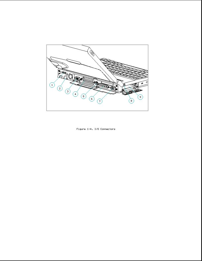
1.AC power
2.Automobile Adapter
3.Serial
4.198-pin external options
5.Keyboard/mouse
6.Parallel
7.External monitor
8.Numeric keypad
9.PCMCIA
AC Power Connector
When the computer is docked in the convenience base and the convenience base is turned on, AC power is applied to the computer's AC power connector. (The 198-pin connector carries all other signals between the two units.)
Automobile Adapter Connector
The computer has an automobile adapter connector that accepts an 18.5 volt, 1.73 amp DC input from the Automobile Adapter. This connector is covered by an access door (Figure 1-5).
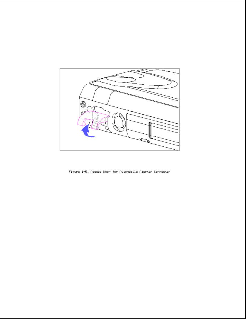
NOTE: The automobile adapter converts 12 volts DC from the automobile to 18.5 volts DC for use by the computer.
>>>>>>>>>>>>>>>>>>>>>>>>>>>>>>>>> CAUTION <<<<<<<<<<<<<<<<<<<<<<<<<<<<<<<<<
The computer has an access door for the automobile adapter connector that is designed to allow only one type of power input (AC or DC) to be connected at a time (Figure 1-5). Do not attempt to defeat this protective feature of the door or internal damage to the computer may result.
>>>>>>>>>>>>>>>>>>>>>>>>>>>>>>>>>>>>><<<<<<<<<<<<<<<<<<<<<<<<<<<<<<<<<<<<<<
Serial Connector
The serial connector supports the serial interface which meets EIA RS232C specifications.
198-Pin External Options Connector
The 198-pin external options connector handles the signal interface between the computer and the expansion base or convenience base.
NOTE: When connected to an expansion base, power to the computer is carried through the 198-pin connector (DC power).

Keyboard/Mouse Connector
The keyboard/mouse connector can be connected to a PS/2 mouse or an external enhanced keyboard. Connecting the mouse/keyboard connector to a mouse disables the integrated trackball, while connecting the mouse/keyboard connector to an external keyboard disables the internal keyboard.
Parallel Connector
The parallel connector supports the parallel interface which meets EPP 1.9 specifications.
External Monitor Connector
The external monitor connector provides an output for an external monitor with a maximum resolution of 1024 x 768 lines.
NOTE: The computer can simultaneously display on an external monitor and the integrated display panel.
Numeric Keypad
Connecting the numeric keypad connector to an external numeric keypad disables the embedded numeric keypad feature.
PCMCIA Connector
The computer has a PCMCIA connector accessible through a PCMCIA slot on the left side of the computer (refer to "PCMCIA Slot" in Section 1.6). The PCMCIA connector supports the PCMCIA interface which meets PCMCIA 2.1 specifications.
1.6 Functional Descriptions
This section covers functional descriptions of key parts and features of the computer. For assembly/disassembly instructions for the parts described in this section, refer to Chapter 4.
System Board
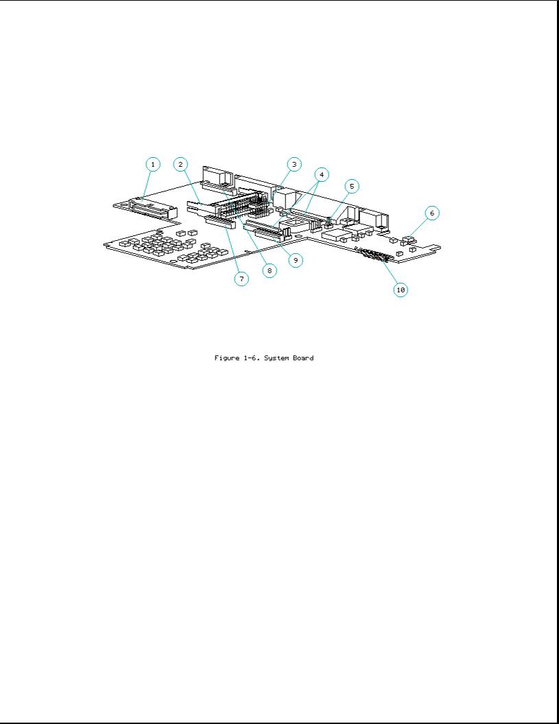
The system board (Figure 1-6) provides the following:
o Connector for removable hard drive [1]
o PCMCIA connector [2] (refer to "PCMCIA Slot")
oBoard-to-board connection to the following devices:
-Power interface board (PIB) [3]
-Processor board [4]
-Memory expansion board (on underside of system board)
o Cable connection to the following devices:
-Internal AC power supply board [5]
-Fan [6]
-Internal keyboard [7]
-Display [8]
-Diskette drive [9]
-LED cable assembly for front-mounted LEDs (on underside of system board)

o Battery charging circuitry and battery contacts [10] for battery pack
o External input/output (I/O) connectors (Figure 1-4)
o DC-to-DC power supply (refer to "DC-to-DC Power Supply" in this section)
o 256 Kbyte flashable shared system ROM and keyboard ROM
o 4 or 8 MB base RAM (depending on the model)
o System controller, which provides the following:
-Interface to the processor board for memory management (including memory refresh)
-Two DMA controllers
-Two interrupt controllers
-Clock generator
-Programmable interval timer
-System management interrupt (SMI) support logic
-Power management features
o Peripheral controller, which provides the following:
-Integrated keyboard controller
-Industry Standard Architecture (ISA) support logic
-Circuit for interfacing to the hard drive
-Control of parallel and serial interfaces, including serial interfaces for a numeric keypad, mouse/keyboard, and internal trackball
o PCMCIA controller
o Local bus video controller
o Diskette drive controller
o Docking sense logic
o Secondary temperature sensor for controlling the fan (refer to "Temperature Sensors")
DC-to-DC Power Supply
The DC-to-DC power supply is integrated into the system board. It converts DC voltage input to regulated 3.3 volts, 5 volts, and 12 volts DC. The DC

voltage input comes from one of the following sources:
o Internal AC power supply o Battery pack
o Automobile adapter
o 198-pin external options connector (from expansion base) o Auxiliary battery
To replace the DC-to-DC power supply, the system board must be replaced.
Processor Board
The SL Enhanced Intel486 processor has an integrated coprocessor and is upgradeable by replacing the processor board (Figure 1-7). The system automatically adjusts to the new configuration. In addition, the processor board contains the primary temperature sensor (refer to "Temperature Sensors").
Some models have a heat sink attached. The computer comes with one of the following processors:
o 486 DX4/75 MHz
o 486 DX2/50 MHz
o 486 DX2/40 MHz
NOTE: The 75 MHz processor is also available as an upgrade option.
Temperature Sensors
The primary temperature sensor is located on the processor board and the secondary temperature sensor is located on the system board. These sensors turn the fan on when the system approaches maximum reliable operating temperatures.
If |
the |
temperature continues to rise, a system management interrupt |
(SMI) |
||
is |
generated that creates a |
pop-up window (depicting a |
thermometer) |
to warn |
|
the user of the temperature |
overload and the unit goes |
into Standby |
within |
||
several seconds. If the temperature continues to rise, |
the computer |
turns |
|||
itself |
off. |
|
|
|
|
NOTE: The temperature sensors are integrated into the processor board and the system board. To replace a temperature sensor, the appropriate board must be replaced.
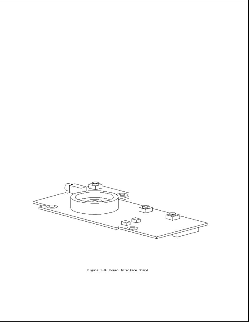
Power Interface Board (PIB)
The power interface board (PIB) (Figure 1-8) is mounted to the system board by a 16-pin connector. The PIB provides the following features:

o Numeric keypad connector
o Speaker and speaker amplifier o Power switch
o Standby button o Display switch
o The following LEDs:
-Power/standby
-Scroll lock
-Caps lock
-Num lock
Refer to Section 1.4 for more information on the controls and LEDs listed above.
Memory Expansion Board
The 4 or 8 MB base RAM memory (depending on the model) may be increased by adding an optional memory expansion board (Figure 1-9). The memory expansion board plugs directly into the back side of the system board (Section 4.6).
The system supports the following 3.3 volt memory expansion boards (which operate at 70ns):

o 4 MB o 8 MB o 16 MB
NOTE: Some early memory expansion boards for the Concerto Family of Personal Computers (option kit numbers 144790-001 and 144790-002) operate at 80 ns and do not function properly when installed in the Compaq LTE Elite Family of Personal Computers, which operate at
70 ns. Use only Compaq LTE Elite memory expansion boards (Table 3-2).
Refer to the table in Section 5.3 for a list of total RAM memory based on available system memory and memory obtained from the expansion board.
Internal AC Power Supply (AC-to-DC)
The computer is powered by a high-efficiency, board-mounted, internal AC-to-DC power supply (Figure 1-10). The power supply provides the computer with an 18.5 volt DC output for running all computer functions, including charging the internal battery pack.
Fan
The internal fan (Figure 1-11) draws in fresh air through vent holes in the PCMCIA compartment door, then exhausts it out the back of the computer.
The fan operates on 5 volts and is controlled by temperature sensors located near the internal power supply and the processor board. The fan is designed to turn on automatically when the system approaches maximum reliable operating temperatures (refer to "Temperature Sensors" in this section).
The fan is integrated into the input/output (I/O) bracket/fan assembly. To replace the fan, the I/O bracket/fan assembly must be replaced.
>>>>>>>>>>>>>>>>>>>>>>>>>>>>>>>>> CAUTION <<<<<<<<<<<<<<<<<<<<<<<<<<<<<<<<<
To properly ventilate the computer, allow at least a 3-inch (7.62 cm) clearance at the back and sides of the unit.
>>>>>>>>>>>>>>>>>>>>>>>>>>>>>>>>>>>>><<<<<<<<<<<<<<<<<<<<<<<<<<<<<<<<<<<<<<
Keyboard
The internal keyboard is connected to the system board by a flex cable. In addition to the internal keyboard, there is a connector for an external keyboard/mouse.
Battery Pack
The removable internal nickel metal hydride (NiMH) battery pack connects to the computer through a set of battery contacts mounted on the system board. Battery charging functions are controlled by the DC-to-DC converter on the system board. The battery pack contains RAM memory that saves the last recorded battery operating time and battery fuel gauge values.
Refer to Appendix B for information on increasing battery pack operating time, ensuring battery gauge accuracy, conditioning the battery pack, and disposal of a used battery pack.
>>>>>>>>>>>>>>>>>>>>>>>>>>>>>>>>> WARNING <<<<<<<<<<<<<<<<<<<<<<<<<<<<<<<<<
Do not crush, puncture, or incinerate the battery pack or short the battery pack external contacts. Do not open a battery pack, as this damages the pack, makes it unusable, and exposes potentially harmful battery components. There are no field-serviceable parts located inside the battery pack.
>>>>>>>>>>>>>>>>>>>>>>>>>>>>>>>>>>>>><<<<<<<<<<<<<<<<<<<<<<<<<<<<<<<<<<<<<<
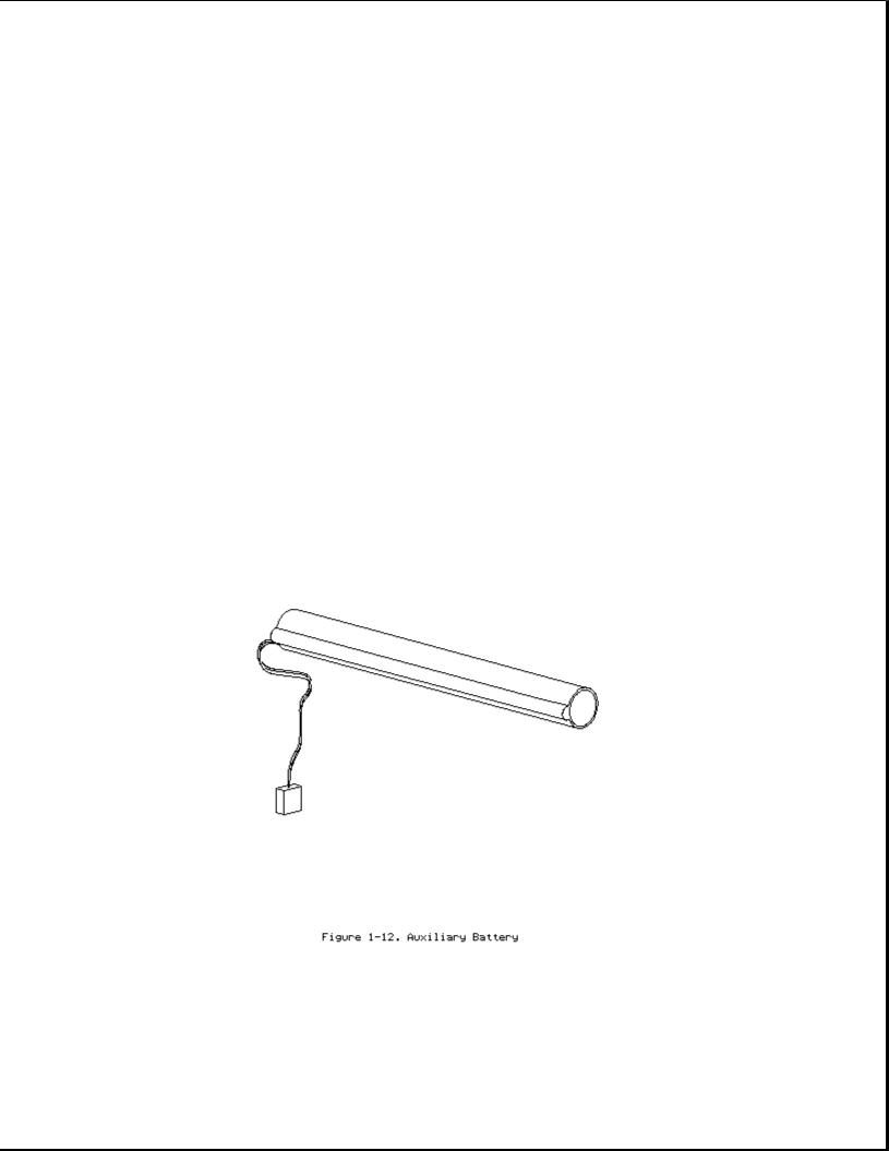
Auxiliary Battery
The internal auxiliary battery (Figure 1-12), mounted on the I/O bracket, supplies voltage to the system real-time clock and maintains alarm, time, date, and configuration information when the battery pack and external power sources are removed. In addition, the auxiliary battery protects RAM

memory for a one-minute period during Standby to allow a battery pack to be replaced.
The auxiliary battery has a nickel cadmium cell that supplies 7.2 volts for 50 mAmp hours. The auxiliary battery recharges when the computer is on while connected to an external power source or the battery pack. It takes approximately 10 hours to recharge a fully discharged auxiliary battery using AC power and approximately 20 hours to recharge it using the battery pack.
>>>>>>>>>>>>>>>>>>>>>>>>>>>>>>>>> WARNING <<<<<<<<<<<<<<<<<<<<<<<<<<<<<<<<<
Do not crush, puncture, or incinerate the auxiliary battery or short the auxiliary battery external contacts. Do not open an auxiliary battery, as this damages the battery, makes it unusable, and exposes potentially harmful battery components. There are no field-serviceable parts located inside the battery.
>>>>>>>>>>>>>>>>>>>>>>>>>>>>>>>>>>>>><<<<<<<<<<<<<<<<<<<<<<<<<<<<<<<<<<<<<<
>>>>>>>>>>>>>>>>>>>>>>>>>>>>>>>>> CAUTION <<<<<<<<<<<<<<<<<<<<<<<<<<<<<<<<<
If the computer is unused for approximately 60 days without being connected to an external power source, a fully charged auxiliary battery will drain to a critically low level. This may result in loss of alarm, time, and date information. If this happens, recharge the auxiliary battery or replace it if it is defective (refer to Section 4.8). Run Computer Setup to restore the alarm, time, and date information (refer to Section 1.8).
>>>>>>>>>>>>>>>>>>>>>>>>>>>>>>>>>>>>><<<<<<<<<<<<<<<<<<<<<<<<<<<<<<<<<<<<<<
NOTE: CMOS password and configuration information is copied to an EEPROM so that it is not lost if the auxiliary battery is unplugged or discharged.
Diskette Drive
The standard 11 mm diskette drive is connected to the system board by a cable. The drive reads and writes to 3.5-inch 1.44 MB (high density) and 720 kilobyte (double density) diskettes. With the proper software support, the drive is also capable of reading and writing to 1.2 MB Japanese standard diskettes.
Hard Drive

The 2.5-inch hard drive (Figure 1-13) is user-removable from the front of the computer (Section 4.12). The hard drive release button allows the drive to be removed without disassembling the computer. A connector on the hard drive enclosure mates to a connector on the system board.
NOTE: The hard drive may have either a metal handle (Figure 1-13) or a plastic pull tab that is attached directly to the hard drive enclosure.
Hard drive security clips can be installed to prevent the hard drive from being removed (refer to Section 4.12). When the security clips are installed, a lock label should be attached to the front of the hard drive to indicate that the drive is locked in place. The computer must be partially disassembled to remove the security clips before the hard drive can be removed.
NOTE: The Compaq Diagnostics utilities (which include Computer Setup) reside in a hidden partition on the Compaq LTE Elite hard drive (not in the ROM). There is no preinstalled software on a new spare hard drive. When installing a new spare hard drive, the hidden partition must be created, the diagnostics utilities must be installed, and the C: partition must be formatted before restoring any data
(Section 4.12). On the option kit hard drives, the hidden partition
is already created and the diagnostics utilities are already installed.
IMPORTANT: The hard drive must be handled with care. Refer to the cautions listed in Section 4.12.
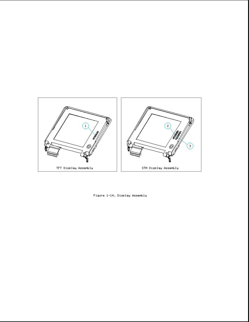
Display Assembly
The display assembly (Figure 1-14) is connected to the system unit by clutches, a display cable and a ground cable. The display assembly includes an integrated trackball board and an inverter board. The color and black-and-white TFT display assemblies have an externally adjustable brightness control slide [1]. The color STN display assembly has two externally adjustable control slides: one for contrast [2] and one for brightness [3]. The display assembly comes with one of the following panels, depending on the model:
o 9.5-inch color STN o 9.5-inch mono TFT o 8.4-inch color TFT o 9.5-inch color TFT
IMPORTANT: In order to optimize display quality and ensure regulatory
compliance, many of the parts in the 9.5-inch color TFT display
can be replaced only by replacing the entire display assembly (Section 4.9).
Refer to Section 5.4 for display specifications.
NOTE: A certain number of pixels in the display panel are allowed to be nonfunctional due to limitations in LCD technology.
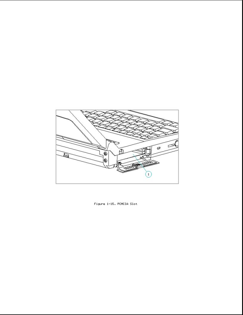
PCMCIA Slot
The PCMCIA connector is mounted to the system board. The connector is accessible through the PCMCIA slot [1], (Figure 1-15), which is covered by a PCMCIA compartment door. The slot accommodates one of the following card combinations:
o Two PCMCIA Type I or Type II cards o One PCMCIA Type III card
The PCMCIA slot supports both 5 volt and 3.3 volt PCMCIA cards in accordance with PC Card Standard Release 2.1 or later and the Exchangeable Card Architecture (ExCA) Specification 1.10.
NOTE: PCMCIA stands for Personal Computer Memory Card International Association. PCMCIA standards continue to change. Many cards on the market do not comply with the PCMCIA specifications and, therefore, do not function properly in the computer. To assist users in selecting compatible PCMCIA devices, Compaq provides a list of third-party cards that have been tested in Compaq products. To ensure compatibility, select a Compaq PCMCIA modem or other vendor cards on the tested list. Call Compaq Reseller Support to have a copy of the list faxed to you.
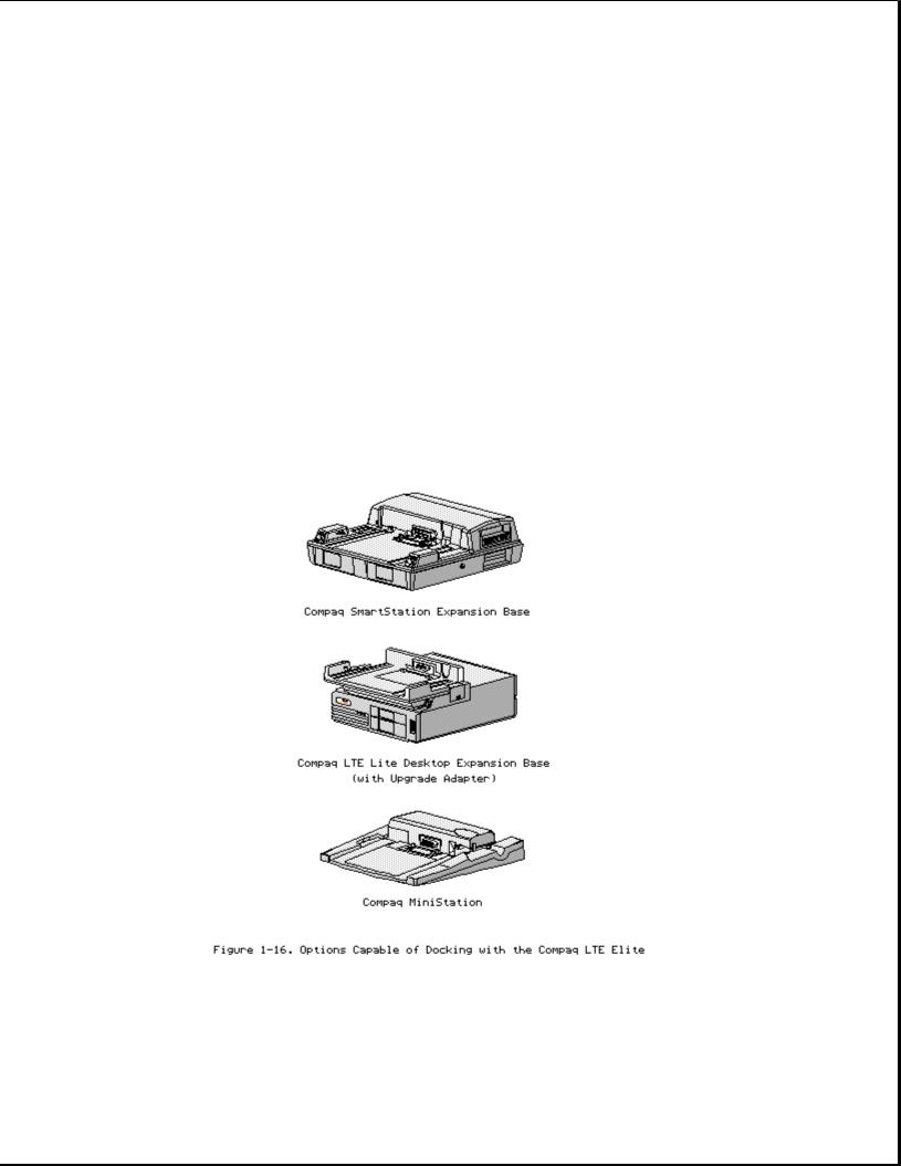
1.7 Docking Options
The Compaq LTE Elite docks with the following options (Figure 1-16):
o Compaq SmartStation expansion base
o Compaq LTE Lite Desktop Expansion Base (with an Upgrade Adapter) o Compaq MiniStation/EN and MiniStation/TR convenience bases
Refer to Appendix D for more information on docking and undocking.
1.8 Running Computer Setup
The Computer Setup utility resides in a hidden partition on the hard drive.

Run Computer Setup for the following situations:
o To configure options
o To update alarm, time, date, or password information
NOTE: Alarm, time, and date information can be lost if the computer is unused for approximately 60 days without charging the internal battery pack or without AC power being connected (refer to "Auxiliary Battery" in Section 1.6). If this information is lost, run Computer Setup to restore it.
IMPORTANT: Use AC power during Computer Setup procedures. A low battery condition could initiate Standby and interrupt the program.
To run Computer Setup, complete the following steps:
1.Turn on or restart the computer.
2.Press the F10 key as soon as the cursor moves to the upper-right corner of the screen.
3.When prompted, select the desired language.
4.Select Computer Setup from the Configuration and Diagnostics menu.
5.Follow the instructions on the screen.
1.9 Reprogrammable Flash ROM
The flash ROM can be reprogrammed to update system firmware and provide the most recent level of system functionality. In some cases, problems may be solved by upgrading the ROM.
Erase and reprogram the nonvolatile read only memory (ROM) by using the ROMPaq utility. The ROMPaq utility is available on the Portables ROMPaq Upgrade Diskette, which includes on-screen instructions for implementing the flash ROM upgrade (Table 3-16).
1.10 Power Management
The following power management features are available for conserving AC power and extending battery operating time:
o Advanced Power Management (APM) o Power management settings
o Standby
o Hibernation
Advanced Power Management (APM)
APM is installed on the computer and requires no action from the user to reduce power consumption. APM turns off the processor between keystrokes

and when the system is idle. This function is transparent to the user. APM also provides occasional screen messages about the battery while in the Windows environment (for example, low power condition).
Power Management Settings
You can select power conservation settings through Computer Setup, Power Management, or by pressing the Fn + F7 hotkeys to maximize power for specific requirements. These settings control the power conservation rate and the timeout values for various system components. A timeout is specified period of system or component inactivity. After this period, the system or component (for example, the hard drive) is shut down to conserve power until it is accessed again.
If the power conservation rate and timeouts are not selected, the computer uses the default settings listed in Table 1-3.
Table 1-3. Power Conservation Default Settings
===========================================================================
|
Battery |
Power |
AC Power |
Feature |
Default |
Setting |
Default Setting |
===========================================================================
Standby timeout |
5 |
minutes |
15 |
minutes |
Hard drive timeout |
2 |
minutes |
15 |
minutes |
Screen save timeout |
3 |
minutes |
15 |
minutes |
Display brightness |
75% of rated brightness |
100% |
of |
rated |
brightness |
Processor speed (MHZ) |
100% of rated speed |
100% |
of |
rated |
speed |
===========================================================================
Standby
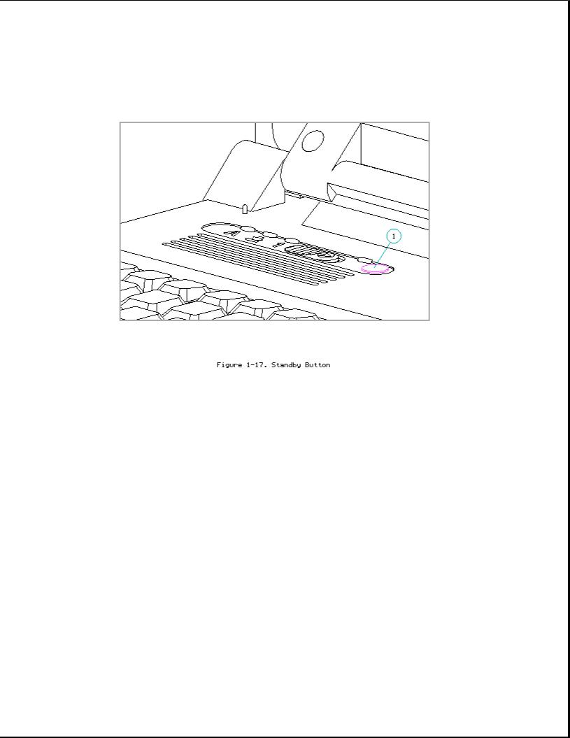
Standby is a power conservation mode for battery or AC power operation during which most of the components (e.g, hard drive, processor, display) shut down.
The computer initiates Standby under the following conditions:
o When the user presses the standby button [1] (Figure 1-17).
o After a timeout occurs.
o When the battery pack voltage reaches a low level (if this option is preselected).
When the user exits Standby (by pressing the standby button again), information returns to the screen at the point where Standby was initiated. Under battery power, the computer can maintain Standby for up to 120 hours.
NOTE: The computer cannot initiate Standby under the conditions listed above when docked in an expansion base or a convenience base. In addition, the computer cannot initiate Standby if there is activity from the hard drive, diskette drive, mouse, keyboard, PCMCIA slot, parallel connector, or serial connector.
 Loading...