


 Loading...
MAINTENANCE
& SERVICE GUIDE
Compaq Deskpro 1000
Series of Personal Computers
Notice
The information in this guide is subject to change without notice.
COMPAQ COMPUTER CORPORATION SHALL NOT BE LIABLE FOR TECHNICAL OR EDITORIAL ERRORS OR OMISSIONS CONTAINED HEREIN; NOR FOR INCIDENTAL OR CONSEQUENTIAL DAMAGES RESULTING FROM THE FURNISHING, PERFORMANCE, OR USE OF THIS MATERIAL.
This guide contains information protected by copyright. No part of this guide may be photocopied or reproduced in any form without prior written consent from Compaq Computer Corporation.
© 1998 Compaq Computer Corporation. All rights reserved. Printed in the U.S.A.
Compaq and Deskpro are registered in the U. S. Patent and Trademark Office.
Microsoft, MS-DOS, Windows, Windows NT, and other names of Microsoft products referenced herein are trademarks or registered trademarks of Microsoft Corporation.
Intel and Pentium are registered trademarks of Intel Corporation. MMX is a trademark of Intel Corporation.
Product names mentioned herein may be trademarks and/or registered trademarks of their respective companies.
The software described in this guide is furnished under a license agreement or nondisclosure agreement. The software may be used or copied only in accordance with the terms of the agreement.
Maintenance & Service Guide
Compaq Deskpro 1000 Series of Personal Computers
First Edition (January 1998)
Part Number 333806-001
Spare Part Number 333835-001
Compaq Computer Corporation
CPS

|
CONTENTS |
|
preface |
|
|
Symbols and Conventions ......................................................................................................... |
vii |
|
Technician Note........................................................................................................................ |
viii |
|
System Serial Number .............................................................................................................. |
viii |
|
Locating Additional Information.............................................................................................. |
viii |
|
chapter 1 |
|
|
Product Description |
|
|
1.1 |
Compaq Deskpro 1000 Series of Personal Computer Models ........................................... |
1-2 |
1.2 |
Features............................................................................................................................... |
1-3 |
1.3 |
System Design .................................................................................................................... |
1-4 |
|
1.3.1 Design Overview ....................................................................................................... |
1-4 |
1.4 |
Preloaded Software............................................................................................................. |
1-5 |
1.5 |
Computer Features.............................................................................................................. |
1-5 |
|
1.5.1 Front Panel Controls and LEDs ................................................................................. |
1-5 |
|
1.5.2 Drive Positions........................................................................................................... |
1-6 |
|
1.5.3 Rear Panel Connectors............................................................................................... |
1-7 |
1.6 |
Enhanced Keyboard............................................................................................................ |
1-8 |
chapter 2 |
|
|
Troubleshooting |
|
|
2.1 |
Power-On Self Test (POST) ............................................................................................... |
2-1 |
|
2.1.1 POST Error Messages................................................................................................ |
2-1 |
2.2 |
CMOS Setup Utility ........................................................................................................... |
2-4 |
|
2.2.1 Preparing the Computer ............................................................................................. |
2-5 |
|
2.2.2 Clearing the Password ............................................................................................... |
2-5 |
2.3 |
Troubleshooting Without Diagnostics................................................................................ |
2-5 |
|
2.3.1 Checklist for Solving Minor Problems ...................................................................... |
2-5 |
|
2.3.2 Power Problems ......................................................................................................... |
2-6 |
|
2.3.3 Diskette Drive Problems ............................................................................................ |
2-7 |
|
2.3.4 Display Problems ....................................................................................................... |
2-8 |
|
2.3.5 Printer Problems ........................................................................................................ |
2-9 |
|
2.3.6 Hard Drive Problems ............................................................................................... |
2-10 |
|
2.3.7 Hardware Installation Problems............................................................................... |
2-11 |
|
2.3.8 CD-ROM Drive Problems ....................................................................................... |
2-12 |
|
2.3.9 Memory Problems.................................................................................................... |
2-12 |
chapter 3 |
|
|
Illustrated Parts Catalog |
|
|
3.1 |
System Unit ........................................................................................................................ |
3-2 |
3.2 |
Mass Storage Devices......................................................................................................... |
3-3 |
3.3 |
Cables ................................................................................................................................. |
3-4 |
3.4 |
Standard and Optional Boards ............................................................................................ |
3-5 |
3.5 |
Keyboards........................................................................................................................... |
3-6 |
3.6 |
Miscellaneous Hardware Kit .............................................................................................. |
3-7 |
3.7 |
Miscellaneous Plastics Kit.................................................................................................. |
3-8 |
Contents iii

3.8 |
Miscellaneous Parts ............................................................................................................ |
3-9 |
3.9 |
Shipping Boxes................................................................................................................... |
3-9 |
3.10 Documentation ................................................................................................................. |
3-9 |
|
chapter 4
Removal and Replacement Preliminaries
4.1 Electrostatic Discharge Information ................................................................................... |
4-1 |
4.1.1 Generating Static........................................................................................................ |
4-1 |
4.1.2 Preventing Electrostatic Damage to Equipment ........................................................ |
4-2 |
4.1.3 Personal Grounding Methods .................................................................................... |
4-2 |
4.1.4 Grounding Workstations............................................................................................ |
4-3 |
4.1.5 Personal Grounding Equipment................................................................................. |
4-3 |
4.1.6 Recommended Materials and Equipment .................................................................. |
4-4 |
4.2 Service Considerations ....................................................................................................... |
4-4 |
4.2.1 Tools and Software Requirements ............................................................................. |
4-4 |
4.2.2 Screws........................................................................................................................ |
4-5 |
4.2.3 Cables and Connectors............................................................................................... |
4-5 |
4.2.4 Hard Drives................................................................................................................ |
4-5 |
4.2.5 Plastic Parts................................................................................................................ |
4-5 |
4.2.6 Lithium Battery.......................................................................................................... |
4-5 |
chapter 5
Removal and Replacement Procedures
5.1 |
Serial Number..................................................................................................................... |
5-1 |
|
5.2 |
Disassembly/Assembly Sequence ...................................................................................... |
5-2 |
|
5.3 |
Feet ..................................................................................................................................... |
5-3 |
|
5.4 |
Preparation for Disassembly............................................................................................... |
5-3 |
|
5.5 |
System Unit Cover ............................................................................................................. |
5-4 |
|
5.6 |
Expansion Board ................................................................................................................ |
5-4 |
|
5.7 |
Expansion Board Guide...................................................................................................... |
5-6 |
|
5.8 |
System Board...................................................................................................................... |
5-7 |
|
5.9 |
Graphics Memory ............................................................................................................... |
5-8 |
|
5.10 |
Memory Modules ............................................................................................................. |
5-9 |
|
|
5.10.1 Installing a SIMM Module .................................................................................... |
5-11 |
|
|
5.10.2 Installing a DIMM Module.................................................................................... |
5-12 |
|
5.11 |
Power Supply.................................................................................................................. |
5-13 |
|
5.12 |
Microprocessor ............................................................................................................... |
5-14 |
|
|
5.12.1 Passive Heat Sink (P55C/166) ............................................................................... |
5-14 |
|
|
5.12.2 Active Heat Sink (P55C/200) ................................................................................ |
5-16 |
|
5.13 |
Front Bezel Assembly .................................................................................................... |
5-18 |
|
5.14 |
LED Retainer Assembly ................................................................................................. |
5-19 |
|
5.15 |
LED Cables .................................................................................................................... |
5-20 |
|
5.16 |
Power Button .................................................................................................................. |
5-21 |
|
5.17 |
Bezel Blank .................................................................................................................... |
5-22 |
|
5.18 |
Replacement Battery....................................................................................................... |
5-23 |
|
5.19 |
Mass Storage Devices..................................................................................................... |
5-24 |
|
|
5.19.1 Drive Positions....................................................................................................... |
5-24 |
|
|
5.19.2 Drive Cage ............................................................................................................. |
5-25 |
|
|
5.19.3 3.5-Inch Drive........................................................................................................ |
5-26 |
|
|
5.19.4 5.25-Inch Drive...................................................................................................... |
5-27 |
|
iv Contents

chapter 6
Jumper Information
6.1 System Board Jumpers ....................................................................................................... |
6-1 |
6.1.1 Power-On Password Jumpers (CPW) ........................................................................ |
6-3 |
6.1.2 Flash EPROM Type Selection (EP)........................................................................... |
6-4 |
6.1.3 CPU External Clock (Bus) Frequency (CLK) ........................................................... |
6-4 |
6.1.4 CPU to SRAM Data Transacting Mode Selection (SRAM)...................................... |
6-5 |
6.1.5 Jumper Settings.......................................................................................................... |
6-5 |
6.1.6 Clearing Configuration .............................................................................................. |
6-5 |
6.1.7 Changing the Real-Time Clock (RTC) Battery ......................................................... |
6-5 |
6.2 Hard Drives ........................................................................................................................ |
6-6 |
6.2.1 1.6-GB IDE Hard Drive Jumper Settings .................................................................. |
6-6 |
chapter 7
Utilities
7.1 CMOS Setup Utility ........................................................................................................... |
7-1 |
7.1.1 Using the CMOS Setup Utility .................................................................................. |
7-1 |
7.1.1.1 Safeguarding CMOS Settings ........................................................................... |
7-1 |
7.1.1.2 Restoring CMOS Settings ................................................................................. |
7-1 |
7.1.2 Important CMOS Settings ......................................................................................... |
7-1 |
7.1.2.1 Standard CMOS Setup ...................................................................................... |
7-1 |
7.1.2.2 BIOS Features Setup ......................................................................................... |
7-2 |
7.1.3 Passwords................................................................................................................... |
7-2 |
7.1.3.1 Establishing a Password.................................................................................... |
7-2 |
7.1.3.2 Entering a Password.......................................................................................... |
7-2 |
7.1.3.3 Disabling a Password ........................................................................................ |
7-2 |
7.1.3.4 Changing a Password ........................................................................................ |
7-3 |
7.1.3.5 Clearing a Password.......................................................................................... |
7-3 |
7.1.4 IDE HDD Auto Detection.......................................................................................... |
7-3 |
7.1.5 Save and Exit Setup ................................................................................................... |
7-3 |
7.1.6 Exit Without Saving................................................................................................... |
7-4 |
7.2 Upgrading the BIOS ........................................................................................................... |
7-4 |
7.3 Configuring Windows Display and Monitor ...................................................................... |
7-4 |
7.3.1 Supported Resolutions ............................................................................................... |
7-5 |
7.3.2 Changing Monitor Type Manually in Windows 95 .................................................. |
7-5 |
7.3.3 Setting Graphics Resolution ...................................................................................... |
7-5 |
7.3.4 Establishing a Password in Windows 95 ................................................................... |
7-5 |
7.4 Diagnostics Software .......................................................................................................... |
7-5 |
chapter 8
Specifications
8.1 |
System ................................................................................................................................ |
8-1 |
8.2 |
Drives ................................................................................................................................. |
8-5 |
8.3 |
Mouse ................................................................................................................................. |
8-7 |
8.4 |
Keyboard ............................................................................................................................ |
8-7 |
8.5 |
Supported Graphics Resolutions ........................................................................................ |
8-8 |
appendix A |
|
|
Connector Pin Assignments......................................................................................................... |
A-1 |
|
Contents v

appendix B
Power Cord Set Requirements
General Requirements ............................................................................................................. |
B-1 |
Country-Specific Requirements .............................................................................................. |
B-2 |
appendix C
Hard Drives
Device 0/Device 1 Relationship......................................................................................... |
C-1 |
Cable Select ....................................................................................................................... |
C-1 |
IntelliSafe - SMART.......................................................................................................... |
C-1 |
Automatic Soft-Drive Types.............................................................................................. |
C-2 |
vi Contents

preface
This Maintenance & Service Guide is a troubleshooting guide that can be used for reference when servicing the Compaq Deskpro 1000 Series of Personal Computers.
Compaq Computer Corporation reserves the right to make changes to the Compaq Deskpro 1000 Series of Personal Computers without notice.
Symbols and Conventions
The following words and symbols mark special messages throughout this guide:
CAUTION: Text set off in this manner indicates that failure to follow directions could result in damage to equipment or loss of data.
!WARNING: Text set off in this manner indicates that failure to follow directions in the warning could result in bodily harm or loss of life.
Text set off in this manner presents clarifying information, specific instructions, commentary, sidelights, or other points of information.
The following format conventions distinguish elements of the text throughout this guide:
„Drive letters that are not in command lines are presented in uppercase type as shown here: drive A.
„Directory names that are not in command lines are presented in uppercase type as shown here: DIRECTORY.
„The file names are presented in uppercase italic type as shown here: FILENAME.
„The names of commands are presented in lowercase as shown here: install, or a:\install.
„Commands that are to be entered at the system prompt may be shown on a separate line.
„When you need to type information without pressing Enter, you are directed to "type" the information.
„When you need to type information and press Enter, you are directed to "enter" the information.
Compaq 1000 Series of Personal Computers |
vii |

Technician Note
!WARNING: Only authorized technicians trained by Compaq should attempt to repair this equipment. All troubleshooting and repair procedures are detailed to allow only subassembly/module-level repair. Because of the complexity of the individual boards and subassemblies, no one should attempt to make repairs at the component level or to make modifications to any printed wiring board. Improper repairs can create a safety hazard. Any indication of component replacement or printed wiring board modifications may void any warranty or exchange allowances.
CAUTION: To properly ventilate the computer system, you must provide at least 3-inches (7.62-cm) of clearance on the front and back of the computer.
!WARNING: The computer is designed to be electrically grounded. To ensure proper operation, plug the AC power cord into a properly grounded electrical outlet only.
System Serial Number
The serial number is displayed on the right side of the cover on the right front corner, and above the expansion board area on the rear of the computer.
Locating Additional Information
The following documentation is available to support the computer:
„Compaq Reference Guide
„Compaq QuickFind, a subscription reference service
„Compaq Safety & Comfort Guide
„Compaq Service Advisories and Bulletins
„Compaq Service Quick Reference Guide
„Compaq Technical Reference Guide
„Illustrated Parts Map (poster)
„Technical Training Guides
viii Preface
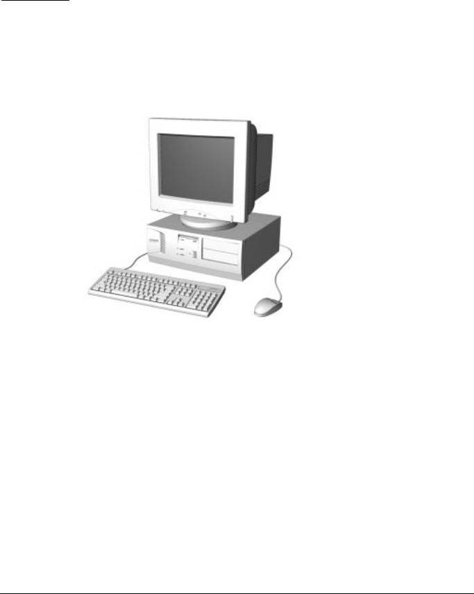
chapter 1
PRODUCT DESCRIPTION
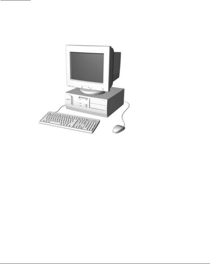
This chapter describes the model offerings and features of the Compaq Deskpro 1000 Series of Personal Computers.
Figure 1-1. Compaq Deskpro 1000 Series of Personal Computers
Compaq Deskpro 1000 Series of Personal Computers 1-1

1.1Compaq Deskpro 1000 Series of Personal Computer Models
The Compaq Deskpro 1000 Series of Personal Computers is available in desktop configurations described in the following sections.
Table 1-1
Desktop Models
Configuration |
|
|
|
Internal |
|
Code |
Processor |
Hard Drive |
Memory |
Cache |
Graphics |
BWF1 |
P55C/166 |
1.6 GB |
16 MB |
256 KB |
S3 Trio64V2/DX |
|
|
|
|
|
|
BWF2 |
P55C/200 |
1.6 GB |
16 MB |
256 KB |
S3 Trio64V2/DX |
|
|
|
|
|
|
All models have maximum expandable memory up to 256 MB.
1-2 Product Description
1.2 |
Features |
|
|
|
|
|
|
|
Table 1-2 |
||
|
Features |
||
|
|
|
|
|
Item |
Description |
|
|
Processor |
Intel Pentium Processor with MMX Technology |
|
|
Speed (MHz) |
166 |
|
|
|
200 |
|
|
|
|
|
|
Cache |
|
|
|
L2 (KB), (write-through, direct mapped) |
256 |
|
|
|
|
|
|
Architecture |
PCI/ISA |
|
|
CMOS RAM, battery backed |
242-byte |
|
|
Plug and Play capability |
Standard |
|
|
|
|
|
|
Chipset |
VIA Apollo 590VP |
|
|
|
|
|
|
ROM BIOS |
Flash memory device |
|
|
|
|
|
|
Memory |
|
|
|
SIMM, 72-pin, non-parity, 66 MHz, EDO |
|
|
|
(SIMMs or DIMMs standard but not both) |
|
|
|
Base (MB) |
16 |
|
|
Maximum (MB) |
256 |
|
|
SIMM sockets |
4 |
|
|
|
|
|
|
Memory |
|
|
|
DIMM, 168-pin, non-parity, 66 MHz, SDRAM, |
|
|
|
(SIMMs or DIMMs standard but not both) |
|
|
|
Base (MB) |
16 |
|
|
Maximum (MB) |
256 |
|
|
DIMM sockets |
2 |
|
|
|
|
|
|
Bays |
|
|
|
3.5-inch Internal |
2 |
|
|
3.5-inch External |
1 |
|
|
5.25-inch External |
2 |
|
|
|
|
|
|
Diskette drive |
|
|
|
Standard 3.5-inch drive bay (MB) |
1.44 |
|
|
|
|
|
|
Hard drive |
|
|
|
Standard EIDE with drive fault prediction (GB) |
1.6 |
|
|
|
|
|
|
Expansion slots |
|
|
|
PCI/ISA/combination |
3/3/1 |
|
|
|
|
|
|
Graphics |
|
|
|
S3 Trio64V2/DX Enhanced 64-bit |
1 |
|
|
Graphics (MB) |
|
|
|
|
|
|
|
I/O ports |
|
|
|
Standard |
Serial (2) |
|
|
|
Parallel |
|
|
|
USB (2) |
|
|
|
Monitor |
|
Keyboard
Mouse
continued
Compaq Deskpro 1000 Series of Personal Computers 1-3

Table 1-2 continued
Item |
Description |
|
Power supply |
200 watt, 115 VAC, 6.0 A/230 VAC, 3.0 A |
|
|
|
|
Power supply fan |
Standard |
|
|
|
|
Internal piezo speaker |
Standard |
|
|
|
|
Internal battery |
Standard |
|
|
|
|
Operating System |
Windows 95 |
|
|
|
|
Two-button mouse |
Standard |
|
|
|
|
Compaq Enhanced keyboard |
|
|
with MS Windows-specific keys |
Standard |
|
|
|
|
1.3System Design
This section presents a design overview and functional descriptions of the key components of the Compaq Deskpro 1000 Series of Personal Computers. All replaceable components are identified in Chapter 3, and removal/replacement instructions are presented in Chapter 5.
1.3.1Design Overview
The desktop models of the Compaq Deskpro Series of Personal Computers use a conventional ATX chassis to house the removable system board, expansion boards, power supply, and mass storage devices.
All internal components are accessible when the cover—held in place by three screws—is
removed. The front bezel is a separate assembly and is attached to the chassis with release latches.
The system board is easily removed from the chassis after the cover is removed. Details of the disassembly procedure are found in Chapter 5, “Removal and Replacement Procedures.”
A removable 3.5-inch drive cage is located to the left center of the chassis. This drive cage can be pulled out from the top, after removing the two screws securing it to the chassis, to provide access to cable connections and to the screws securing the drives to the drive cage. The removable drive cage accommodates one external diskette drive and two internal hard drives. The fixed 5.25-inch drive cage is located to the right of the removable cage and holds a maximum of two drives.
Both the removable and the fixed drive cages allow drive installation without the use of rails. Four screws secure a drive to the drive cage, and ensure proper alignment of the drive within the cage.
Expansion boards are installed vertically into the system board. A single screw secures each expansion board to the chassis.
The power supply is mounted in the right rear corner of the chassis. The power supply is held in place by four screws that are installed through the rear panel of the chassis and a single retaining screw on the inside on the chassis.
1-4 Product Description
1.4Preloaded Software
This computer is shipped with Windows 95 installed as the operating system.
The following software is preloaded on the computer:
„Compaq Online Safety & Comfort Guide
„Microsoft Windows 95
1.5Computer Features
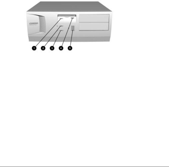
1.5.1Front Panel Controls and LEDs
Figure 1-2. Front Panel Controls and LEDs
1 |
Diskette Drive Activity Light |
Turns on when the diskette drive is reading or writing. |
2 |
Power-On Light |
Turns on when the computer is turned on. |
3 |
Hard Drive Activity Light |
Turns on when the hard drive is reading or writing. |
4 |
Diskette Eject Button |
Ejects a loaded diskette. |
5 |
Power Button |
Turns the computer on and off. |
When the hard drive light 3 or diskette drive light 1 is on, the drive is either reading information from the disk or storing information on the disk.
Compaq Deskpro 1000 Series of Personal Computers |
1-5 |
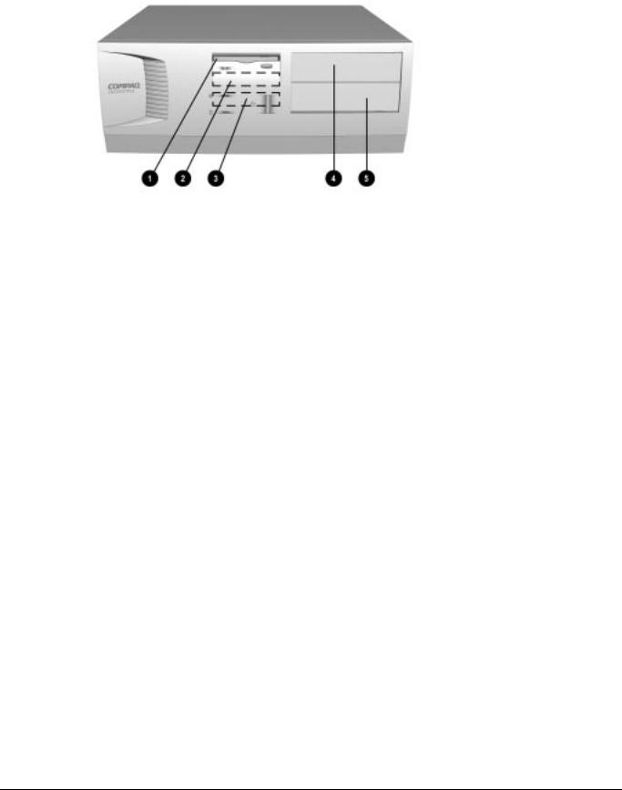
1.5.2Drive Positions
Figure1-3. Drive Positions on the Compaq Deskpro 1000 Desktop Computer
1 One 3.5-inch 1.44-MB diskette drive
2 One 3.5-inch third-height drive bay for optional drive
3 One 3.5-inch third-height drive bay for primary hard drive
4 One 5.25-inch half-height drive bay for optional drive
5 One 5.25-inch half-height drive bay for optional drive
1-6 Product Description
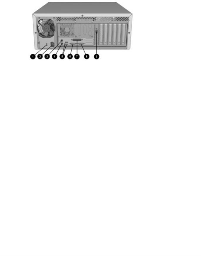
1.5.3Rear Panel Connectors
Figure 1-4. Rear Panel Connectors
1 Voltage Select Switch (115 V U.S. or 230 V to match geographical requirements)
2 Power Cord Connection
3 Mouse Connector
4 Keyboard Connector
5 Universal Serial Bus (USB) Connectors
6 Serial Connector
7 Parallel Port Connector
8 Serial Connector
9 Monitor Connector
Compaq Deskpro 1000 Series of Personal Computers |
1-7 |
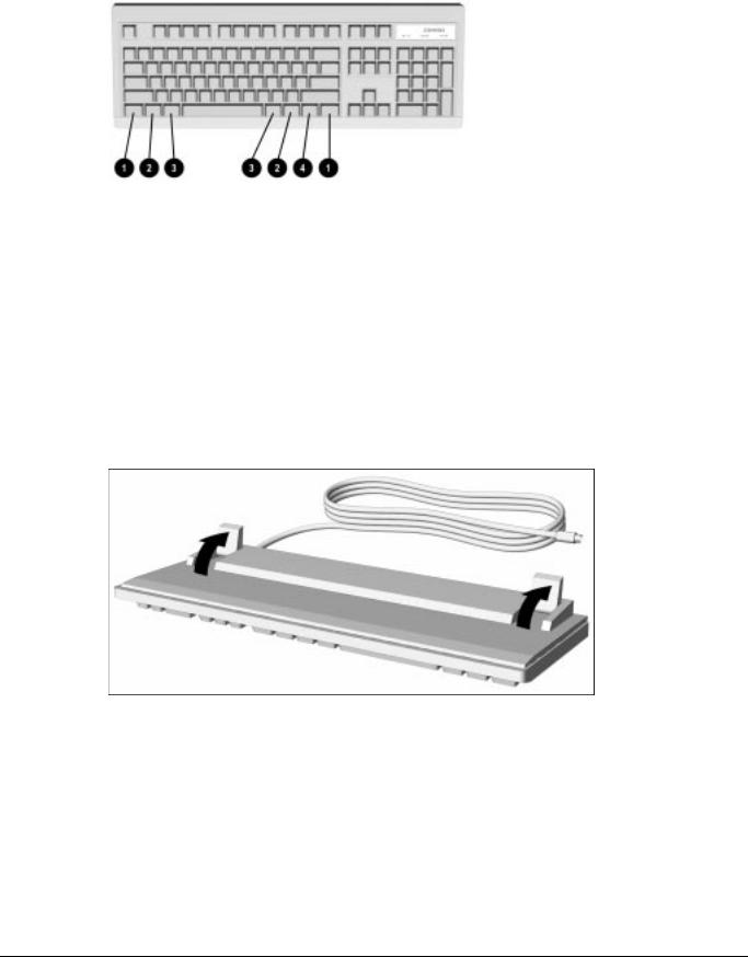
1.6Enhanced Keyboard
Figure 1-5. Enhanced Keyboard
1 |
Ctrl |
Used in combination with another key. Its effect depends on the |
|
|
software application you are using. |
2 |
Windows Logo Keys |
Opens the Windows Start menu. Used in combination with another |
|
|
key. Its effect depends on the software application you are using. |
3 |
Alt |
Used in combination with another key. Its effect depends on the |
|
|
software application you are using. |
4 |
Windows Application Key |
Used (like the right mouse button) to open pop-up menus in a |
|
|
Microsoft Office application. May perform other functions in other |
|
|
software applications. |
The keyboard has feet on the bottom that enable the user to tilt the keyboard to a more comfortable typing angle.
Figure 1-6. Keyboard Tilt Feet
1-8 Product Description

chapter 2
TROUBLESHOOTING
This chapter provides troubleshooting information for the Compaq Deskpro 1000 Series of Personal Computers including:
„Power-On Self Test (POST)— POST messages listed in Table 2-1 include a description of the error, the probable cause, and the recommended action that should be taken to resolve the error condition.
„CMOS Setup Utility—Computer Setup options are available through the CMOS Setup Utility.
„Troubleshooting Without Diagnostics—Tables 2-2 through 2-9 include a problem/solution checklist for power, diskette drive, display, printer, hard drive, CDROM, and memory.
Adherence to the procedures and precautions described in this chapter is essential for proper service.
Some features may not be available on all models.
2.1Power-On Self Test (POST)
The POST procedure is embedded in the system BIOS and performs a series of diagnostic tests that automatically run when the system is turned on. POST checks the following assemblies to ensure that the computer system is functioning properly:
„Keyboard
„Mouse
„System board
„Memory modules
„Video
„Diskette drives
„Hard drives
„Power supply
„Controllers
If POST detects an error in the system, an error condition is indicated by an audible and/or visual message. Table 2-1 explains the error codes and suggests a recommended course of action.
2.1.1POST Error Messages
An error message may be followed by a prompt to press F1 to continue or press DEL to enter Setup.
Compaq Deskpro 1000 Series of Personal Computers |
2-1 |

|
Table 2-1 |
|
|
Power-On Self-Test Messages |
|
|
|
|
Message |
Probable Cause |
Recommended Action |
The computer |
No system memory is present. |
Add system memory. |
beeps: |
|
|
the beep consists of |
|
|
continuous long beeps
The computer |
A video error has occurred |
beeps: |
and the BIOS cannot initialize |
the beep consists of |
the video screen to display |
one long beep |
any additional information. |
followed by two short |
|
beeps |
|
Ensure the VGA card is installed correctly and that the monitor cable is well connected.
BIOS ROM |
The checksum of the BIOS |
Replace the BIOS. |
Checksum Error - |
code in the BIOS chip is |
|
System Halted |
incorrect, indicating the BIOS |
|
|
code may have become |
|
|
corrupt. |
|
|
|
|
CMOS Battery |
CMOS battery is no longer |
Replace the battery. |
Failed |
functional. |
|
|
|
|
CMOS Checksum |
The checksum of CMOS is |
A checksum error may indicate that CMOS has |
Error - Defaults |
incorrect, so the system loads |
become corrupt. This error may have been caused |
Loaded |
the default equipment |
by a weak battery. Check the battery and replace |
|
configuration. |
if necessary. |
|
|
|
CPU at nnnn |
Displays the running speed of |
None. |
|
the CPU. |
|
|
|
|
Display Switch Is Set |
The display switch on the |
Incorrectly |
system board can be set to |
|
either monochrome or color. |
|
This message indicates the |
|
switch is set to a different |
|
setting than indicated in |
|
Setup. |
Determine which setting is correct, and then either turn off the system and change the jumper, or enter Setup and change the Video selection.
Press Esc to Skip |
The system is testing memory. |
The user may press Esc to skip the full memory |
|
Memory Test |
|
test. |
|
|
|
|
|
Floppy Disk(s) Fail |
Cannot find or initialize the |
Ensure the controller is installed correctly. If no |
|
|
floppy drive controller or the |
diskette drives are installed, be sure the Diskette |
|
|
drive. |
Drive selection in Setup is set to None. |
|
|
|
|
|
Hard Disk Install |
Cannot find or initialize the |
This will occur only if the BIOS supports low level |
|
Failure |
hard drive controller or the |
format. Current BIOS does not support low-level |
|
|
drive. |
format. |
|
|
|
|
|
|
|
Continued |
|
2-2 Troubleshooting

Table 2.1 Continued
Message |
Probable Cause |
Recommended Action |
Hard Disk(s) |
The system has run specific |
Diagnosis Failure |
disk diagnostic routines. This |
|
message appears if one or |
|
more hard disks return an |
|
error when the diagnostics |
|
run. |
Hard disk may be damaged, and may need to be replaced.
Keyboard Error or |
Cannot initialize the keyboard. Ensure the keyboard is attached correctly and no |
No Keyboard |
keys are pressed during POST. To purposely |
Present |
configure the system without a keyboard, set the |
|
error halt condition in Setup to Halt on All but |
|
Keyboard. The BIOS then ignores the missing |
|
keyboard during POST. |
|
|
Keyboard is Locked |
This message usually |
Out - Unlock the |
indicates that one or more |
Key |
keys have been pressed |
|
during the keyboard tests. |
Ensure no objects are resting on the keyboard.
Memory Test |
This message displays during None. |
|
a full memory test, counting |
|
down the memory areas being |
|
tested. |
|
|
Memory Test Fail |
If POST detects an error |
|
during memory testing, |
|
additional information appears |
|
giving specifics about the type |
|
and location of the memory |
|
error. |
If this happens often, the memory module may need to be replaced.
Primary Master Hard |
POST detects an error in the |
Disk Fail |
primary master IDE hard drive. |
Ensure the controller is installed correctly, the cable is attached correctly, and the hard disk jumper is set to primary master. If no hard drive is installed, be sure the hard drive selection in Setup is set to None.
Primary Slave Hard |
POST detects an error in the |
Disk Fail |
primary slave IDE hard drive. |
Ensure the controller is installed correctly, the cable is attached correctly, and the hard disk jumper is set to primary slave. If no hard drive is installed, be sure the hard drive selection in Setup is set to None.
Secondary Master |
POST detects an error in the |
Hard Disk Fail |
secondary master IDE hard |
|
drive. |
Ensure the controller is installed correctly, the cable is attached correctly, and the hard disk jumper is set to secondary master. If no hard drive is installed, be sure the hard drive selection in Setup is set to None.
Secondary Slave |
POST detects an error in the |
Hard Disk Fail |
secondary slave IDE hard |
|
drive. |
Ensure the controller is installed correctly, the cable is attached correctly, and the hard disk jumper is set to secondary slave. If no hard drive is installed, be sure the hard drive selection in Setup is set to None.
Compaq Deskpro 1000 Series of Personal Computers |
2-3 |

2.2CMOS Setup Utility
The Award BIOS chip contains the ROM setup information of your computer and serves as an interface between the processor and the rest of the components on the motherboard.
The CMOS Setup Utility, which is built into the BIOS and stored in the CMOS RAM, is executed when the user changes the battery or the existing settings, or when the system detects an error during POST and asks you to run the Setup utility. See Chapter 7, “Utilities,” for instructions on how to use this utility.
Before removing or replacing a subassembly, safeguard the CMOS settings. Write them down, make a print screen of each CMOS setup page, or use a third-party CMOS rescue software to store the settings in a file on a write-protected diskette.
To execute the CMOS Setup Utility:
1.Shut down the operating system.
2.Turn the computer off, then on.
3.Press the Delete key when the message “Press DEL to enter Setup” appears on the lower right hand corner of the screen.
4.Use the arrow keys to highlight the setup feature you want to change.
5.Press Enter to open the selected setup feature.
6.Use the arrow keys to highlight the value you want to change.
7.Use the Page Up or Page Down keys to change the selected value.
8.Follow the on-screen instructions to save the changes and exit, or to exit the utility without saving any changes.
Failure to configure the system correctly can result in loss of data and reduced hard drive capacity.
The CMOS Setup Utility includes the following options:
„Standard CMOS Setup
„BIOS Features Setup
„Chipset Features Setup
„Power Management Setup
„PnP/PCI Configuration Setup
„Load BIOS Defaults
„Load Setup Defaults
„Integrated Peripherals
„Supervisor Password
„User Password
„IDE HDD Auto Detection
„Save and Exit Setup
„Exit without Saving
2-4 Troubleshooting
2.2.1Preparing the Computer
If you encounter an error condition, complete the following steps before starting problem isolation procedures:
1.Ensure proper ventilation. The computer should have a 3-inch (7.6-cm) clearance at the back of the system unit.
2.Turn off the computer and peripheral devices.
CAUTION: Always ensure that the power is off before disconnecting or reconnecting the mouse, keyboard, or any other peripheral devices. Disconnecting or connecting any peripheral devices while the unit power is on can damage the system board.
3.Disconnect any peripheral devices other than the monitor and keyboard. Do not disconnect the printer if you want to test it or use it to log error messages.
4.Install loop-back and terminating plugs for complete testing.
5.Run a diagnostics utility.
2.2.2Clearing the Password
If you have to clear the password before changing any of the CMOS settings, refer to Chapter 7, “Utilities,” for instructions.
2.3Troubleshooting Without Diagnostics
This section describes some simple, preliminary tests and guidelines for troubleshooting the computer without using diagnostics software.
Diagnostics software is not included with this computer. Compaq diagnostics software, Version PC 10.25A, is available at www.compaq.com. Third-party diagnostics software is also available.
2.3.1Checklist for Solving Minor Problems
If you encounter some minor problem with the computer or a software application, go through the following checklist for possible solutions before running any of the diagnostic utilities:
„Is the computer connected to a working power outlet?
„Is the computer turned on and the power light illuminated?
„Are all cables connected properly and seated?
„Is the monitor turned on and the power light illuminated?
„If the monitor is dim, turn up the brightness and contrast controls of the monitor.
„Press and hold any key. If the system beeps, then the keyboard should be operating correctly.
„Are all of the necessary device drivers installed?
„Have all printer drivers been installed for each application?
„Is the CONFIG.SYS file correct?
„Is the AUTOEXEC.BAT file (MS-DOS) or STARTUP.CMD file (OS/2) correct?
Compaq Deskpro 1000 Series of Personal Computers |
2-5 |

„Was a nonbootable diskette loaded in the diskette drive at power-up?
„Are all switch settings correct?
„Have all jumper settings been set as instructed by the configuration utility?
„Was Computer Setup run after installing options (memory, disk drives, expansion boards, etc.) and before installing industry standard architecture (ISA) boards?
2.3.2Power Problems
This section identifies some quick checks for power-related problems.
|
Table 2-2 |
|
Solutions for Power Problems |
|
|
Problem |
Possible Solution |
Computer will not turn on. |
Ensure that the computer is connected to a power source. |
|
Cables to the external power source may be unplugged. Ensure that |
|
cables connecting the computer and the external source are plugged |
|
in properly. |
|
A PCI or ISA card that has been installed may be defective. Remove |
|
any adapter card that was just installed. |
|
|
Computer does not automatically |
The real-time clock (RTC) battery may need to be replaced. See |
display the date and time. |
Chapter 5 for replacement procedures. |
(Date/Time not set) |
|
|
|
Computer powered off |
The unit temperature may have been exceeded. Check the fan for |
automatically. |
function and blockage. |
|
Check to ensure that the power cord is securely plugged into the wall |
|
and the unit. |
|
|
2-6 Troubleshooting

2.3.3Diskette Drive Problems
This section identifies some quick checks for diskette drive–related problems.
Table 2-3
Solutions for Diskette Drive Problems
Problem |
Possible Solution |
|
Diskette drive light stays on. |
1. |
Diskette may be damaged. In Windows 95, run SCANDISK. At the |
|
|
Start menu, highlight Programs, select Accessories, select System |
|
|
Tools, then SCANDISK. |
|
2. |
Diskette could be installed incorrectly. Remove the diskette and |
|
|
reinsert. |
|
3. |
Software program may be damaged. Replace the program |
|
|
diskettes. |
|
4. |
Drive cable is not properly connected. Reconnect drive cable. |
|
|
|
Diskette drive cannot write to |
1. |
Diskette is not formatted. Format the diskette. |
a diskette. |
2. |
Diskette is write-protected. Either use another diskette that is not |
|
||
|
|
write-protected or disable the write protection on the diskette. |
|
3. |
Writing to the wrong drive. Check the drive letter in the path |
|
|
statement. |
|
4. |
Not enough space is left on the diskette. Use another diskette to |
|
|
write the information. |
|
5. |
Diskette write control is disabled. Check the security feature |
|
|
settings in Setup. |
|
|
|
Diskette drive cannot read a |
1. Diskette is not formatted. Format the diskette. |
|
diskette. |
2. |
Using the wrong diskette type for the drive type. Use a diskette that |
|
||
|
|
is compatible with the drive. |
|
3. |
Reading the wrong drive. Check the drive letter in the path |
|
|
statement. |
|
4. |
Diskette drive has been disabled by Computer Setup. Run |
|
|
Computer Setup and enable the diskette drive. |
|
|
|
A problem has occurred with a |
The directory structure is bad, or there is a problem with a file. In |
|
disk transaction |
Windows 95, run SCANDISK. At the Start menu, highlight Programs, |
|
|
select Accessories, select System Tools, then SCANDISK. |
|
|
|
|
Nonsystem disk message. |
Remove the diskette from the drive and press any key. |
|
|
|
|
Drive not found. |
Check the cables for loose connections. |
|
|
|
|
Compaq Deskpro 1000 Series of Personal Computers |
2-7 |

2.3.4Display Problems
This section identifies some quick checks for display-related problems.
Table 2-4
Solutions for Display Problems
Problem |
Possible Solution |
|
Screen is blank. |
1. |
Monitor is not turned on and the monitor light is not on. Turn on the |
|
|
monitor and check that the monitor light is on. |
|
2. |
Screen save has been initiated. Press any key or move the mouse |
|
|
to light the screen. |
|
3. |
Check the cable connection from the monitor to the computer and |
|
|
check the electrical outlet. |
|
4. |
The brightness need adjusting. Adjust the brightness control. |
|
5. |
The energy saver feature has been enabled. Hit any key or type |
|
|
the password. |
|
6. |
The RGB (Red, Green, Blue) input switch on the back of the |
|
|
monitor is incorrectly set. Set the monitor's input switch to 75 ohms |
|
|
and, if there is a sync switch, set it to External. |
|
7. |
If a fixed-sync monitor is used, be sure that the monitor can accept |
|
|
the same sweep rate as the resolution chosen. |
Graphics colors are wrong. |
1. |
Ensure that the Red, Green, and Blue BNC cables are connected |
|
|
to the corresponding monitor connectors. |
|
2. |
Be sure the monitor's RGB inputs are set to 75 ohms. |
Characters are dim. |
1. |
Adjust the monitor's brightness and contrast controls. |
|
2. |
Check that the video cable is securely connected to the graphics |
|
|
card and monitor. |
|
3. |
Set the RGB switch (and sync options, if available) to 75 ohms, |
|
|
with the sync set to External. Refer to the documentation included |
|
|
with the monitor. |
|
|
|
Monitor does not function properly Monitor without the energy saver feature is being used with energy when used with the energy saver saver features enabled. Disable the monitor energy saver feature. features.
Blurry display or requested |
If the graphics controller was upgraded, the correct display drivers |
resolution cannot be set. |
may not be loaded. Install the correct display drivers on the diskette |
|
included in the upgrade kit. |
|
|
The picture is broken up; it rolls, jitters, or blinks.
1.Be sure the monitor cable is securely connected to the computer.
2.In a 2-monitor system or if another monitor is in close proximity, be sure the monitors are not interfering with each other's magnetic field by moving them apart.
Garbled characters on the screen |
The ANSI.SYS driver is not in the CONFIG.SYS file. Add the |
are mixed with text. |
ANSI.SYS driver to the CONFIG.SYS file by adding the following line: |
|
DEVICE = C:\CPQDOS\ANSI.SYS |
|
|
Screen goes blank. |
A screen blanking utility may be installed or energy saver features are |
|
enabled. Press any key or type password. |
|
|
Monitor overheats. |
There is not enough ventilation space for proper airflow. Leave at |
|
least 3 inches (7.6-cm) of ventilation space. Also, be sure there is |
|
nothing on top of the monitor to obstruct air flow. |
|
|
Cursor will not move using the |
The Num Lock key is on. Press the Num Lock key. The Num Lock |
arrow keys on the numeric keypad.light should not be on when you want to use the arrow keys.
2-8 Troubleshooting

2.3.5Printer Problems
This section identifies some quick checks for printer-related problems.
Table 2-5
Solutions for Printer Problems
Problem |
Possible Solution |
|
Printer will not print. |
1. |
Printer is not turned on and online. Turn the printer on and make |
|
|
sure it is online. |
|
2. |
The correct printer drivers for the application are not installed. |
|
|
Install the correct printer drivers for the application. |
|
3. |
If the computer is on a network, you may not have made the |
|
|
connection to the printer. Make the proper network connections to |
|
|
the printer. |
|
|
|
Printer will not turn on. |
The cables may not be connected properly. Reconnect all cables and |
|
|
check the power cord and electrical outlet. |
|
|
|
|
Prints garbled information. |
1. |
The correct printer drivers for the application are not installed. |
|
|
Install the correct printer drivers for the application. |
|
2. |
The cables may not be connected properly. Reconnect all cables. |
|
|
|
Printer is offline. |
The printer may be out of paper. Check the paper tray and refill it if it |
|
|
is empty. Select online. |
|
|
|
|
Compaq Deskpro 1000 Series of Personal Computers |
2-9 |

2.3.6Hard Drive Problems
This section identifies some quick checks for hard drive–related problems.
|
|
Table 2-6 |
|
Solutions for Hard Drive Problems |
|
|
|
|
Problem |
Possible Solution |
|
Hard drive error occurs. |
Hard disk has bad sectors or has failed. Use a utility to locate and |
|
|
block usage of bad sectors. If necessary, reformat the hard disk. |
|
|
|
|
Disk transaction problem. |
Either the directory structure is bad or there is a problem with a file. At |
|
|
the C:\> prompt, run SCANDISK to check for problems. If problems |
|
|
exist, run SCANDISK /AUTOFIX to correct the problems. |
|
|
|
|
Drive not found. |
1. |
Cable could be loose. Check cable connections. |
|
2. |
The system may not have automatically recognized a newly |
|
|
installed device. If Windows 3.1 is installed, run Computer Setup |
|
|
and identify the new device. If Windows 95 is installed, run Device |
|
|
Manager and identify the device. |
|
3. |
If the drive is a secondary drive that has just been installed on the |
|
|
same controller as the primary drive, verify that the jumpers for |
|
|
both drives are set correctly. |
|
|
|
Nonsystem disk message. |
1. |
The system is trying to start from a diskette that is not bootable. |
|
|
Remove the diskette from the diskette drive. |
|
2. |
The system is trying to start from the hard drive but the hard disk |
|
|
has been damaged. Insert a bootable diskette into the diskette |
|
|
drive and restart the computer with Ctrl+Alt+Del. |
|
3. |
Diskette boot has been disabled in Computer Setup. Run |
|
|
Computer Setup and enable diskette boot. |
|
|
|
Hard drive operation seems slow. The hard disk files may be fragmented.
At the C:\> prompt, run SCANDISK to check for problems. If problems exist, run SCANDISK /F to correct the problems. If a large number of lost allocation units is found, run the MS-DOS defragmentation program DEFRAG. See the Microsoft Windows & MS-DOS 6.2 User's Guide for more information.
Alternatively, at the C:\> prompt, run SCANDISK to check for problems. If problems exist, run SCANDISK /AUTOFIX to correct the problems. If a large number of lost allocation units is found, run the MS-DOS defragmentation program DEFRAG. Type HELP SCANDISK for more information.
2-10 Troubleshooting

2.3.7Hardware Installation Problems
This section identifies some quick checks for hardware problems.
Table 2-7
Solutions for Hardware Installation Problems
Problem |
Possible Solutions |
|
A new device is not recognized as |
1. |
The Computer Setup utility has not been run to configure the new |
part of the computer system. |
|
device. Run the Computer Setup utility. |
|
2. |
When the system advised you of changes to the configuration, you |
|
|
did not accept them. Reboot the computer and follow the |
|
|
instructions for accepting the changes. |
|
3. |
The system may not have automatically recognized the new device. |
|
|
If Windows 3.1 is installed, run Computer Setup and identify the |
|
|
new device. If Windows 95 is installed, run Device Manager and |
|
|
identify the device. |
|
4. |
A Plug and Play board may not automatically configure when added |
|
|
if the default configuration conflicts with other devices. Run |
|
|
Computer Setup (Windows 3.1 installed) or run Device Manager |
|
|
(Windows 95 installed) to deselect the automatic settings for the |
|
|
board and choose a basic configuration that doesn’t cause a |
|
|
resource conflict. |
|
5. |
The cables for the new external device are loose or the power |
|
|
cables are unplugged. Check all cables. |
|
6. |
The power switch for the new external device is not turned on. Turn |
|
|
off the computer, turn on the external device, and then turn the |
|
|
computer on to integrate the new device with the computer. |
|
7. |
If the drive is a secondary drive that has just been installed on the |
|
|
same controller as the primary drive, verify that the jumpers for both |
|
|
drives are set correctly. |
|
|
|
The computer supports Plug and |
In Windows 95, onboard serial devices that are assigned to ports other |
|
Play, but the hardware |
than COM1 or COM2, have their configuration saved statically in |
|
configuration settings in Computer |
CMOS. When the system is rebooted, the ROM configures the device |
|
Setup do not match the settings in |
to the static setting; when Windows 95 loads, it configures the device |
|
Windows 95 Device Manager. |
to the configuration set via Device Manager. In such cases, the |
|
|
configuration shown when CMOS Setup is run does not match what |
|
|
was set up via Device Manager. |
|
If these devices must be configured a certain way before Windows 95 loads, then the serial port devices on the system should only be configured to COM1 or COM2 resources. If the system has two serial devices plus a modem, then the first serial device can be COM1 or COM2 or disabled, the modem can be COM1 or COM2 or disabled, and the second serial device can be COM4 or disabled.
Compaq Deskpro 1000 Series of Personal Computers |
2-11 |

2.3.8CD-ROM Drive Problems
This section identifies some quick checks for CD-ROM drive problems.
|
|
Table 2-8 |
|
|
CD-ROM Drive Problems |
|
|
|
Problem |
Possible Solution |
|
Cannot read compact disc. |
1. |
CD is not properly seated in the drive. Eject the CD, correctly seat |
|
|
it in the drive, then reload. |
|
2. |
CD has been loaded upside down. Eject the CD, turn it over, then |
|
|
reload. |
|
|
|
System will not boot from CD-ROM1. |
The CD-ROM boot is not enabled through the CMOS Setup utility. |
drive. |
Run the CMOS Setup utility and set the drive priorities. |
2. |
Ensure that drive cabling and jumpers are set correctly. To boot a |
|
SCSI drive, the drive ID number must be set to 0. |
|
|
Cannot eject compact disc (trayCD is not properly seated in the drive. Turn off the computer and
load unit only). |
insert a thin metal rod into the emergency eject hole and push firmly |
|
(a straightened paper clip can be used). Slowly pull the tray out from |
|
the drive until the tray is fully extended, then remove the CD. |
|
|
CD-ROM device is not detected; driver is not loaded.
CD-ROM drive is not connected properly. Open the computer and check to see that the drive cable is connected properly and the drive jumpers are set correctly.
Some features may not be available on all models.
2.3.9Memory Problems
This section identifies some quick checks for memory-related problems.
|
|
Table 2-9 |
|
|
Memory Problems |
|
|
|
Problem |
Possible Solution |
|
Out of Memory error. |
1. |
In Windows 95, use the Device Manager to check memory |
|
|
configuration. |
|
2. |
The computer has run out of memory to run the application. Check |
|
|
the application documentation to determine the memory |
|
|
requirements. |
|
|
|
Memory count during POST is |
The memory modules may not be installed correctly. Check that the |
|
wrong. |
memory modules have been installed correctly and that mixed EDO |
|
|
and FPM DRAM are in the correct bank, then run the Configuration |
|
|
utility. (If the system contains mixed EDO and FPM DRAMs, the EDO |
|
|
pair is one bank and the FPM pair is another bank.) |
|
|
|
|
Insufficient memory error during |
1. |
Too many Terminate and Stay Resident programs (TSRs) are |
operation |
|
installed. Delete any unnecessary TSRs. |
|
2. |
The computer has run out of memory for the application. Check |
|
|
the memory requirements for the application or add more memory |
|
|
to the computer. |
|
|
|
2-12 Troubleshooting
chapter 3
ILLUSTRATED PARTS CATALOG
This chapter provides an illustrated parts breakdown and a reference for spare parts for the Compaq Deskpro 1000 Series of Personal Computers.
Figure 3-1. Compaq Deskpro 1000 Series of Personal Computers
Compaq Deskpro 1000 Series of Personal Computers |
3-1 |
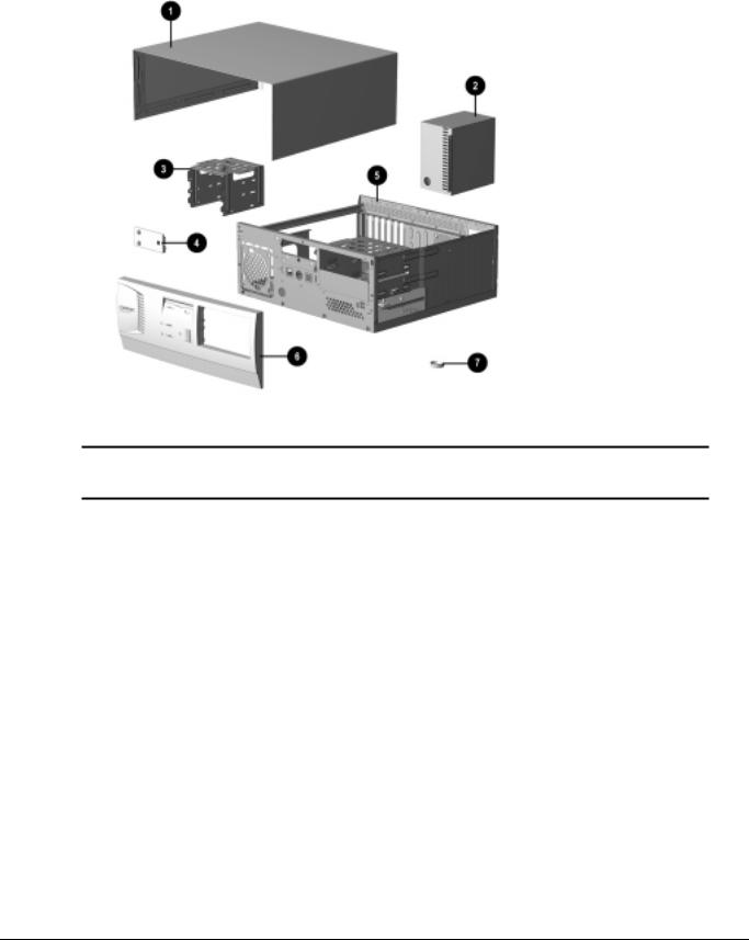
3.1System Unit
Figure 3-2. System Unit
Table 3-1
System Unit Spare Parts
Description |
Spare Part Number |
Warranty Tier |
1 System unit cover |
333833-001 |
A |
|
|
|
2 Power supply, 200W (Includes fan) |
333818-001 |
A |
|
|
|
3 Drive Cage |
333838-001 |
A |
|
|
|
4 LED holder (reference only; part of Miscellaneous Plastics |
|
|
kit) |
|
|
|
|
|
5 Base pan (chassis assembly) |
333834-001 |
A |
|
|
|
6 Front bezel. (Includes power switch cap and bezel blanks) |
333839-001 |
A |
|
|
|
7 Feet (reference only; part of Miscellaneous Plastics kit) |
|
|
|
|
|
3-2 Illustrated Parts Catalog
Loading...